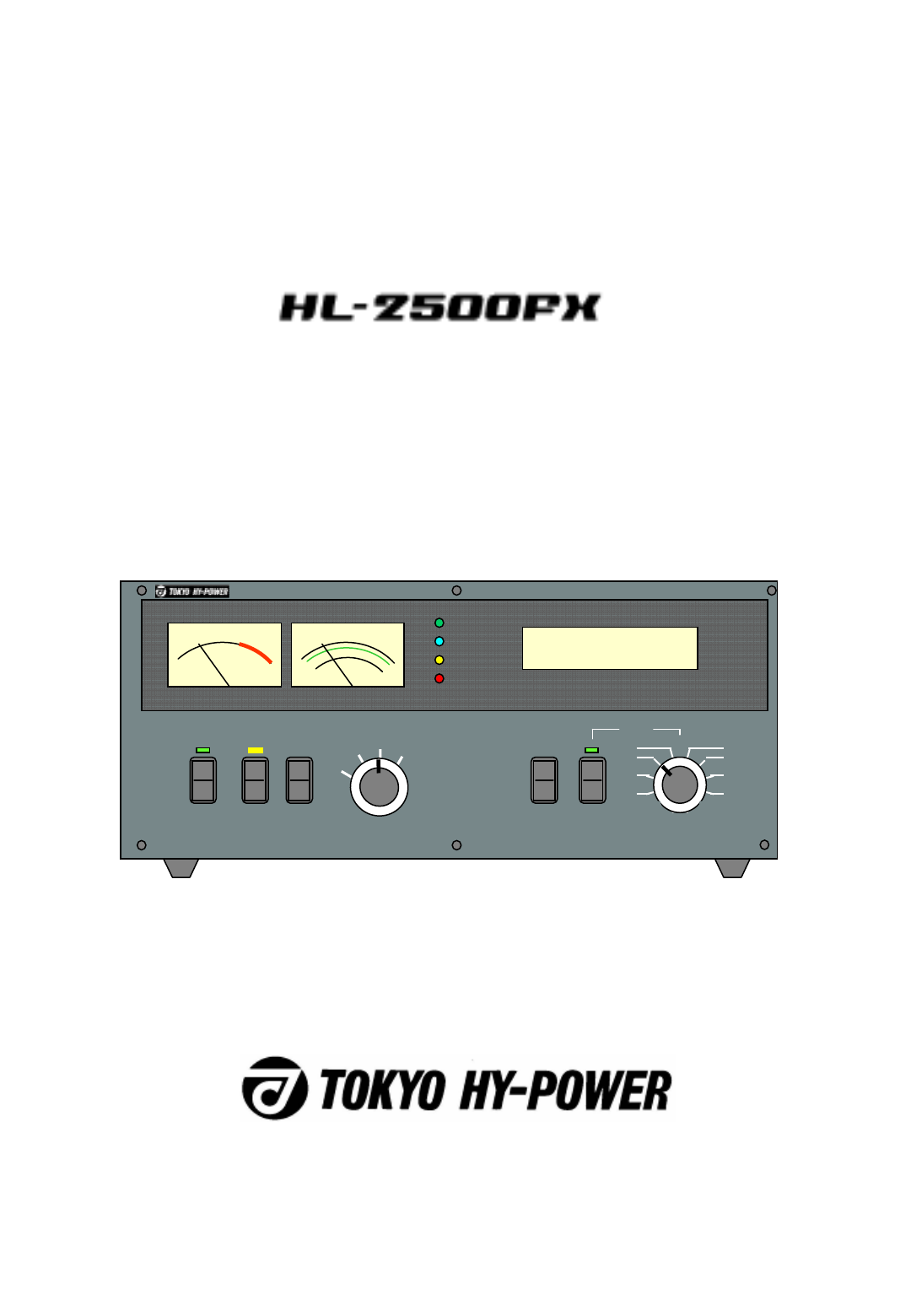
Tokyo Hy Power Labs HL-2500FX HF 50 MHz LINEAR POWER AMPLIFIER User Manual
Tokyo Hy-Power Labs, Inc. HF 50 MHz LINEAR POWER AMPLIFIER
User Manual
-0 -
INSTRUCTION MANUAL
HF ・50MHz LINEAR POWER AMPLIFIER
POWER OPER. METER
Pr
VD ALC
OFF STBY
BAND
AUTO
MAN’L
ON AIR
FAN
ID
PROT
Pf/kW
HF SOLID STATE LINEAR AMPLIFIER HL-2500FX
MAN’L
1.8
3.5
7
10 14
18/21
24/28
50
Pr/VD/ID/ALC
OUTPUT
HI
LO
ANT
A
B
ID

1.Introduction
Thank you for purchasing the HL-2500FX. This compact and
lightweight desktop HF linear power amplifier has a maximum input
power of 2.9 kW. Our solid-state broadband power amp technology
makes it the smallest and lightest in the industry.
Typical output power is 1.5 kW PEP/SSB on HF (1kW on 50MHz)
with the drive power of 85-90 W. The built-in band decoder will let you
forget about the band setting when the amplifier is connected to your
modern radio through such band data cables as ICOM CI-V, DC
voltage (Yaesu and Elecraft K3), and RS-232C (Kenwood). These
data cables are optional parts. The one that matches your radio should
be purchased separately.
2. Cautions
2-1 Unpack the amplifier, check the fan guard at the rear panel fan to
see if there is any damage caused by the physical shock during the
transportation. Fan blades must be free to rotate when powered.
The amplifier is cooled by forced airflow. Several inches of clearance
on the top and the rear wall are necessary to allow for smooth air
intake into the fan. Do not block the air vents on the top cover.
2-2 Keep the amplifier out of direct sunlight, in a cool dry environment.
2-3 Internal high voltages, (AC, DC and RF), are present at all times,
ON AIR or OFF. Internal access should be limited to avoid injury.
2-4 Turn off the AC main power immediately upon any unusual
sounds, sights or odors. Check the multimeter readings of Vd and Id,
the fuses and all cable connections around the amplifier. Please notify
the dealer or the factory of any problems.
2-5 For your safety, do not operate the amplifier without adequate
grounding. A proper ground connection will result in peak performance
and stability, in addition to reduced RF strays or noises.
2-6 To eliminate the RF interference to such home appliances as TV,
FM radio, telephone sets, etc.,
-1 -

it is recommended that clamp-on ferrite cores be inserted at both ends
of the remote control cable, ALC cable, coaxial jumper cable, and
antenna cables, as needed. Also, a common mode AC line filter (near
the AC outlet), and in-line low pass filters on the antenna coaxial
cable, (as necessary), are recommended.
2-7 The amplifier has fast acting sophisticated protection circuits
controlled by the latest microprocessor technology. Please note,
however, any such actions that cause the same fault to occur
repeatedly, will lead to failure of the valuable final power FET
transistors. Also note that the full power CW (or carrier) drive under
the erroneous MANUAL BAND SET leads to the failure of the final
power FET’s (See page 14, Section 10. Trial). In this sense, it is highly
recommended that the amplifier is connected to the radio with Band
Data Cable.
2-8 Before checking inside the amplifier, be sure to wait a few
minutes for the high DC voltage to discharge (monitor Vd meter
reading). The internal potentiometers for RF power detector,
protection circuits, FET bias voltage circuit, etc., are precisely adjusted
at the factory, and should not be altered. Doing so, would require
readjustment with precision measuring instruments.
2-9 DC power supply selection is designed with wide AC line voltage
technology and works with any voltage of 200V to 250V as well as
100V to 125V. 200V to 250V line, however, is recommended for the
best stability and performance. Note that maximum output power is
1kW only, when 100V to 125V is connected. Prepare appropriate AC
power cord plug that fits the outlet at your location.
2-10 Before powering on the amplifier, be sure to connect a dummy
load (50 ohms, 1.5 kW min.) or a well-adjusted antenna to the output
terminal. Operating without any load will cause extreme stress to the
RF power FET’s, although protection circuits should work under critical
conditions.
2-11 Required drive power is slightly less than 100 W to obtain the full
1.5 kW output. Do not attempt to operate with excessive drive from a
high power transceiver. Transmitting high drive RF (over 100 W) into
the amplifier will void the warranty.
-2 -

2-12 Keep the aluminum heat sink and air openings free from dust
and blockages. Periodic cleaning will prevent degraded cooling
efficiency.
2-13 For long continuous operation in RTTY/FM modes, it is
recommended you reduce the RF drive levels by 20% to 30% lower
output than CW/SSB modes.
2-14 To prevent damage to the precision electronic components,
avoid extreme physical shock to the amplifier. If factory service is
required, the amplifier MUST be shipped using the original box and
packaging materials.
3. Features
3-1 Our solid-state broadband design engineers worked to make
the HL-2500KFX, the lightest and most compact 1.5 kW amplifier in
the industry. This world-class compact 1.5 kW amplifier is the
easiest to handle and operate.
3-2 The amplifier is equipped with a newly developed band
decoder. The amplifier’s decoder changes bands automatically as
the data signal is received from the associated HF transceiver’s
frequency bands.
3-3The amplifier’s main PA section includes 6 high power MOS FET
THP2933’s by Microsemi, resulting in 1.5 kW PEP (SSB max.). The
amplifier’s broadband characteristics require no further tuning once
the operating band is selected.
3-4 The amplifier allows operation in full break-in CW mode due to
the use of the amplifier’s high- speed antenna relays (made by
Panasonic).
3-5With the unique duct structure design and the powerful blower
fan, the aluminum heat sink block for RF PA module (and other
components), are effectively cooled. The fan’s quiet operation allows
for even the weakest DX signals to be heard.
-3 -

3-6 The amp utilizes an advanced 16 bit MPU (microprocessor) to run
the various high speed protection circuits such as overdrive, high
antenna SWR, DC overvoltage, band mis-set etc.
3-7 This amplifier is compatible with AC 200 V and 250 V as well as
AC 100V to 125V.
3-8 For the safety of the operator, an Interlock system is employed.
The AC power is shut down if the top cover is removed, and the
automated safety interlock is activated.
3-9 An analog multimeter allows the operator to monitor Pr (Reflected
power), Vd (Drain voltage of power FET), Id (Drain current) and ALC
voltage.
3-10 For future expansion, the amplifier rear panel is equipped with a
control cable connection socket TUNER, this is for the upcoming
model HC-1500AT, auto antenna tuner by Tokyo Hy-Power Labs. in
2013.
-4 -

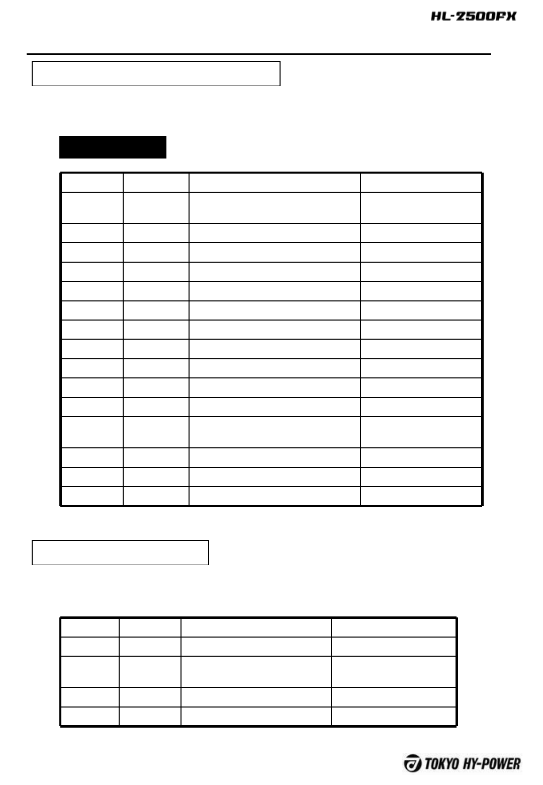
4. Specifications
Frequency : 1.8 ~ 50 MHz all amateur bands including
WARC bands
Mode : SSB, CW, RTTY
RF Drive : 85W typ. (100W max.)
Output Power : 1.5 kW PEP/CW (typ.)
(1 kW on 50 MHz band)
Matching Transceivers
for Auto Band Decoder : Most ICOM, Yaesu, Kenwood, Elecraft K3,
Ten-Tec
Drain Voltage : 50 V (when no RF drive)
Drain Current : 60 A max.
Input Impedance : 50Ω(unbalanced)
Output Impedance : 50Ω(unbalanced)
Final Transistor : THP2933 x 6 (MOS FET by Microsemi)
Circuit : Class AB push-pull
Cooling Method : Forced Air Cooling
MPU : PIC 18F8722
Multi-Meter : Output Power Pf 2.5 kW
Reflected Power Pr 250W
Drain Voltage Vd 60V
Drain Current Id 80A
Input/Output Connectors : UHF SO-239 with low loss Teflon insulator
AC Power : AC 100V ~250V (wide range)
AC Consumption : 3 kVA max. when TX
Dimension : 370 x 145 x 422 mm (W x H x D)
14.6 x 5.7 x 16.6 inches
Weight : Approx. 18 kgs. or 41 lbs.
Accessories : AC Power Cord x 1
RCA Plug (Stereo Type Pair Cable) x 1
Spare Fuse 20 A
(for AC 200V~250V line) x 2
Spare Fuse 20A (In yellow plastic)
(DC58V, for FET drain) x 3
Spare Fuse 1.6 A (Black)
(Miniature Fuse for RF Absolute Over-drive)
x 1
Spare Fuse 3.2 A (Black)
(Miniature Fuse for + 12V Control Circuit Supply
and External AUX, Supply)) x 2
Instruction Manual x 1
Warranty Card x 1
Optional Items : Band data cable to radios
-5 -
5. AC Line Voltage
5-1 The amplifier is designed to work with any AC voltage world
wide, (200- 250 V and 100-125V).
When connected to 100-125V line, maximum available output
power is 1kW on HF and 500W on 6m band.
5-2 The correct AC plug (not included in the package), must be
obtained locally due to the AC plug variations worldwide.
5-3 For the best performance and stability, it is strongly
recommended that you will connect to AC 230V line (200V~250V).
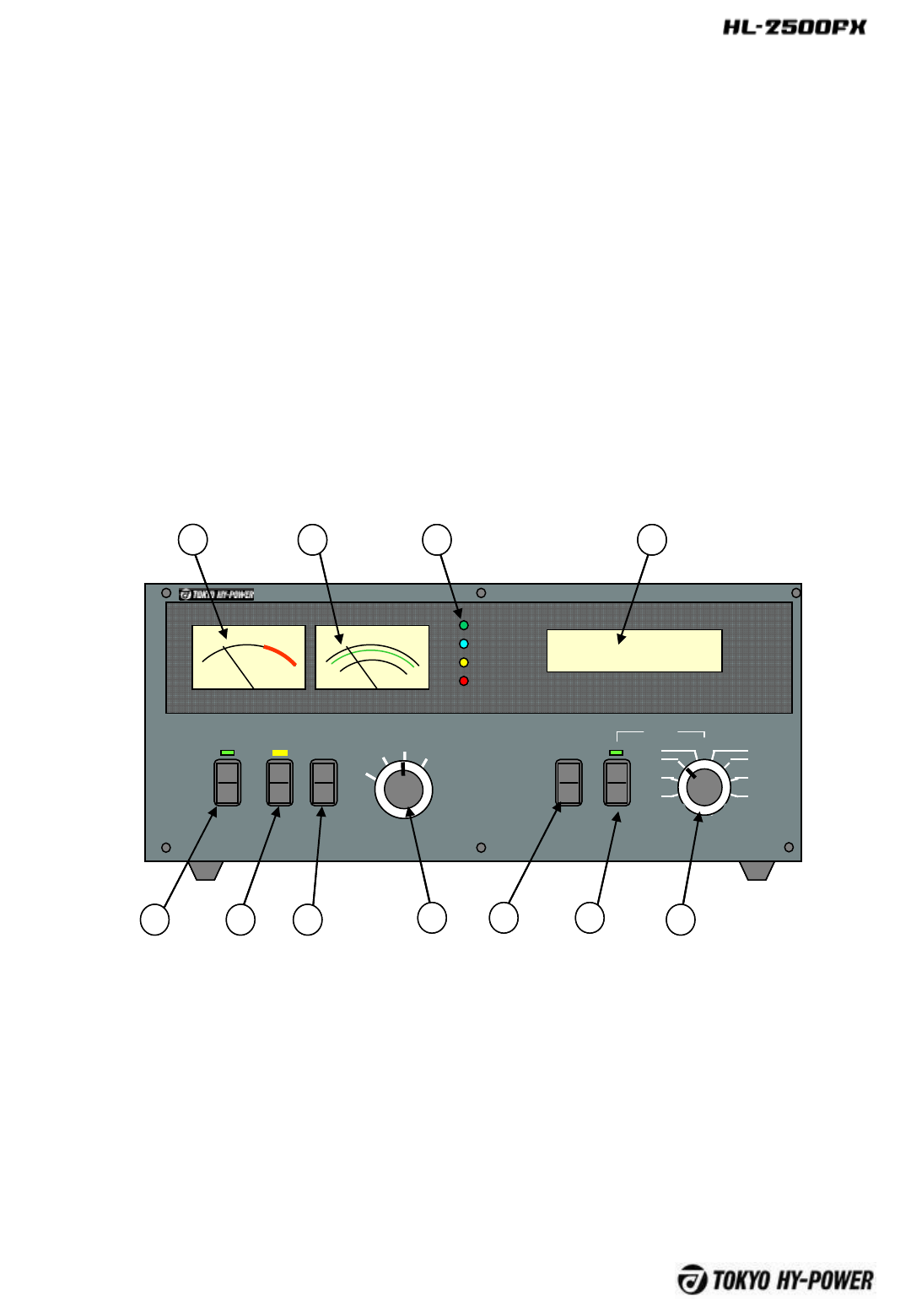
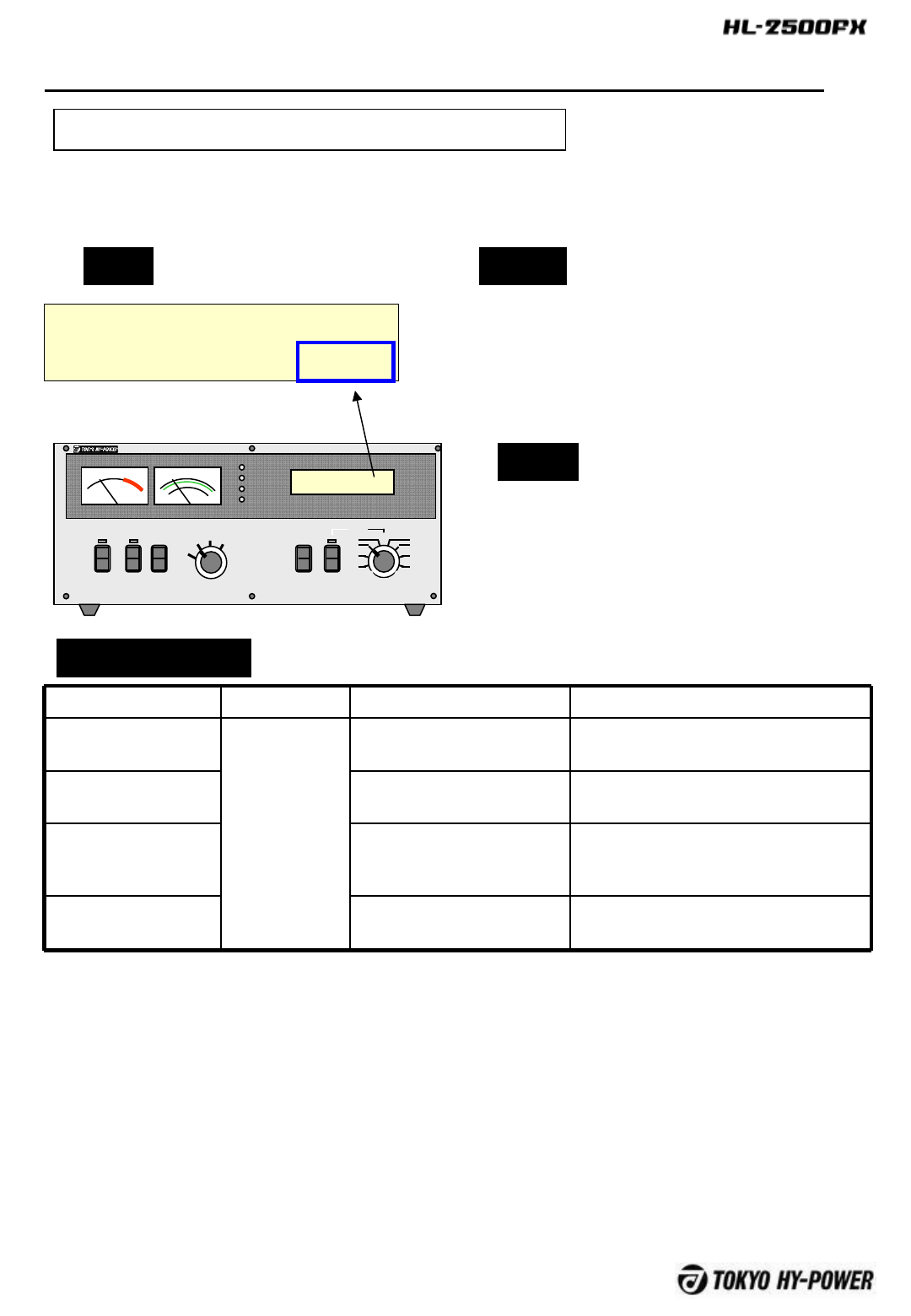
6.Front Panel Description
POWER OPER. METER
Pr
VD ALC
OFF STBY
BAND
AUTO
MAN’L
ON AIR
FAN
ID
PROT
Pf/kW
HF SOLID STATE LINEAR AMPLIFIER HL-2500FX
MAN’L
1.8
3.5
7
10 14
18/21
24/28
50
Pr/VD/ID/ALC
OUTPUT
HI
LO
ANT
A
B
ID
1 2 3 4 5 6 7
8910 11
POWER OPER. METER
Pr
VD ALC
OFF STBY
BAND
AUTO
MAN’L
ON AIR
FAN
ID
PROT
Pf/kW
HF SOLID STATE LINEAR AMPLIFIER HL-2500FX
MAN’L
1.8
3.5
7
10 14
18/21
24/28
50
Pr/VD/ID/ALC
OUTPUT
HI
LO
ANT
A
B
ID
POWER OPER. METER
Pr
VD ALC
OFF STBY
BAND
AUTO
MAN’L
ON AIR
FAN
ID
PROT
Pf/kW
HF SOLID STATE LINEAR AMPLIFIER HL-2500FX
MAN’L
1.8
3.5
7
10 14
18/21
24/28
50
Pr/VD/ID/ALC
OUTPUT
HI
LO
ANT
A
B
ID
1 2 3 4 5 6 7
8910 11
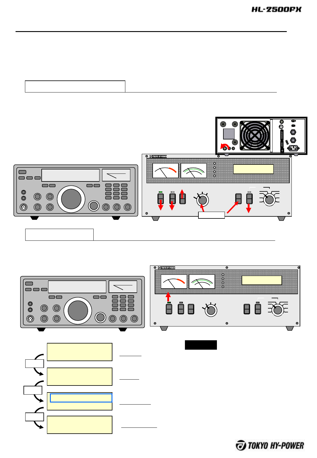
①POWER Main power switch. At OPERATE, the amplifier is ready to go into
ON AIR (TX) mode and at STBY, it is on STAND-BY mode.
③OUTPUT To select High or Low Output levels. At LO, output is
approximately 60% of HI.
④METER To change the multimeter scales. Meter reads Pr, Vd, Id and ALC.
⑤ANT-A/B To Select antenna “A” or “B”. When main power switch is turned
off, it is switched to A.
-6 -

⑥BAND-AUTO/MANUAL
To select band switching methods AUTO or MANUAL. When
using AUTO, the manufacturer for the transceiver in use should be
selected. When the band data cable is not used, MANUAL should be
selected. (See page 19, 10 Operation / Setting)
⑦BAND-MANUAL
Rotary switch for band change in the manual mode. While the
transceiver is on Receive (RX) mode, turn to select the desired
frequency band operate. The switches will not work when the
transceiver and the amplifier are in Transmit (TX) mode.
⑧METER (PF) Meter to read forward output power, PF. Full scale
is 2.5 kW, and it reads average power.
⑨MULTIMETER
Pr (Reflected power from antenna), VD (FET drain voltage), ID
(FET drain current) and ALC voltage are shown on the scale as
selected by ④MANUAL select switch. Full scales are; PR: 250W,
VD: 60V, Id: 80A, ALC: -10V.
⑩ONAIR, FAN, ID, PROT (LED)
ON AIR : Lights when the amplifier is in transmit (TX) mode.
FAN : Lights when cooling fan is running at high speed.
When the heat sink temperature reaches 35℃,cooling
fan speed will continuously increase to enhance cooling
capacity.
ID : Excessive ID Indicator (55A). Depending on the
band and antenna situation, high drain currency may flow into FET’s.
If 55A is exceeded, this LED lights to indicate that high ID is being
drawn (This light does not necessarily mean a failure of the amplifier.
However, if it lights too often, or too long, it is possible the drive
power should be reduced and the antenna should be checked for
SWR, to avoid stress to the FET’s)
PROT : Lights when protection circuit shuts down the
amplifier. Various protection circuits are built in such as Over-drive,
Band mis-set, high Ant-SWR, Over-temperature etc. Detailed
explanations will follow.
⑪LCD PANEL Displays modes of operation and protection circuit.
Detailed explanation will follow.
-7 -
FUSE
FUSE
ANT B ANT A
INPUT
ALC ADJ ALC SEND
TUNER
SELECT
AC IN
FUSE
FUSE
REMOTE
DC OUT
12V2A
CONT
SERIAL
USB
G
N
D
1 2 3 4 5 6
7 8 910 12 1611 13 14 15 17
FUSE
FUSE
FUSE
FUSE
FUSE
FUSE
FUSEFUSE
ANT B ANT A
INPUT
ALC ADJ ALC SEND
TUNER
SELECT
AC IN
FUSE
FUSE
REMOTE
DC OUT
12V2A
CONT
SERIAL
USB
G
N
D
1 2 3 4 5 6
7 8 910 12 1611 13 14 15 17
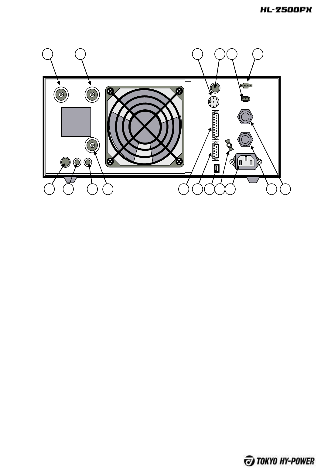
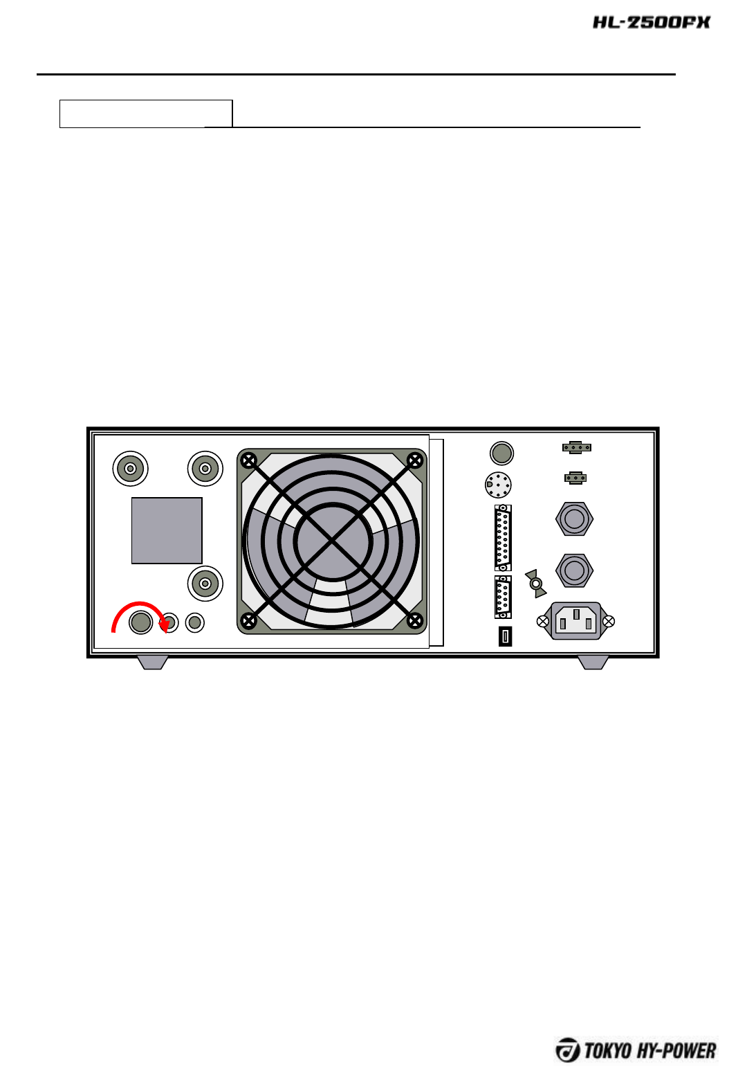
7Rear Panel Description
①ANT-B RF Output Connector. Connect coax cable to the antenna B.
②ANT-A RF Output Connector. Connect coax cable to the antenna A.
③TUNER DIN Socket. Connect the control cable from External Auto
Antenna Tuner, HC-1500AT and or HC-1.5KAT.
④SELECT Switch to select the transceiver (i.e. “CI-V” for ICOM CI-V, “I”
for ICOM DC Voltage, “Y” for Yaesu, “K” for Kenwood, “Aux1-3” for three
auxiliary positions of N.C./no connection.).
⑤DC OUT 12V 2A, Auxiliary DC power supply terminal.
⑥REMOTE Connector to switch the amp ON and OFF in the remote
location.
⑦ALC ADJ. Potentiometer to adjust ALC voltage level. Minus 10 V is
available at maximum, when turned fully clockwise.
Factory setting is 0 volts, with the pot turned fully counter-clockwise.
-8 -

⑧ALC RCA Jack for ALC Voltage Output. Negative DC voltage
appears at the center pin, which is fed back to the ALC terminal of
the transceiver. ALC is used to keep the amplifier output power at
certain limits. Also it is useful when the transceiver output power
is higher than 100W (Seen page 18, Section 9-C. 7 ALC
Adjustment). Also consult with your HF transceiver’s user manual.
⑨SEND RCA Jack. Connect the control cable from the ACC
terminal (or SEND, TX GND etc.) of the transceiver. Electrical
conditions are 12V DC of open voltage at receive mode (RX), and
short current of 35mA at transmit mode (TX).
⑩INPUT RF input connector. Connect the coax jumper cable
from the transceiver.
⑪CONT D-Sub (15pin) Socket. Connect the band data cable to
the transceiver/
⑫SERIAL Serial connector for control. (D-Sub 9pin) To access
to CPU controller board through serial data bus.
⑬USB USB Connector. To access to CPU board. This socket in
connected to serial connector ⑫.
⑭GND Ground terminal.
⑮AC IN 230V AC Main Socket. Socket for the AC power cord.
(Socket is EMI filtered.)
⑯⑰Fuse Apair of fuses for AC Mains. 250V/20A glass fuse.
-9 -
-10 -
7 LCD Panel Description
Basic Signs
LCD displays the status of the amp in various situations. Capacity is 24 characters in
two rows.
1.8MHz AUT-CIV ANT-A
STBY Temp35C OUT_Hi
Following s are the common signs to appear while amp is in operation.
BAND
1.8MHz
3.5MHz
7MHz
10MHz
14MHz
18MHz
21MHz
24MHz
28MHz
50MHz
EXCD
BAND SET
MODE
Manual
AUT-CIV
AUT-YAE
AUT-KEN
AUT-TEN
AUT-ICM
AUT-FLX
AUT-ELC
AUT-FRQ
ANTENNA
SELECT
ANT-A
ANT-B
OPERATION
STATUS
STBY
OPER
ONAR
TRCK
TEMPERATURE
(℃)
Temp00C
|
Temp99C
OUTPUT
SETTING
OUT_Hi
OUT_Lo
OUT_LoLIM
Other Signs
TOKYO HY-POWER
HL-2500FX V1.00
PLEASE WAIT
CHECKING CONDITIONS
Initial Messages
24 MHz AUT-CIV ANT-A
PROT BAND MISSET
ACV is 198V
Complete Initial Set-Up
Protection Shutdown
Message
Detailed explanation will
follow.
*21MHz
*28MHz
-11 -
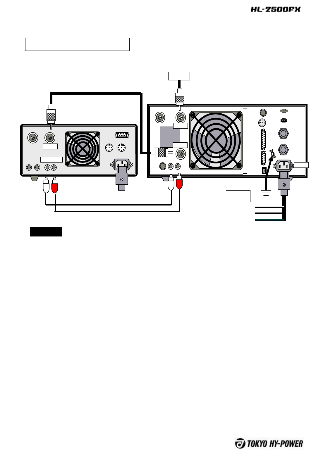
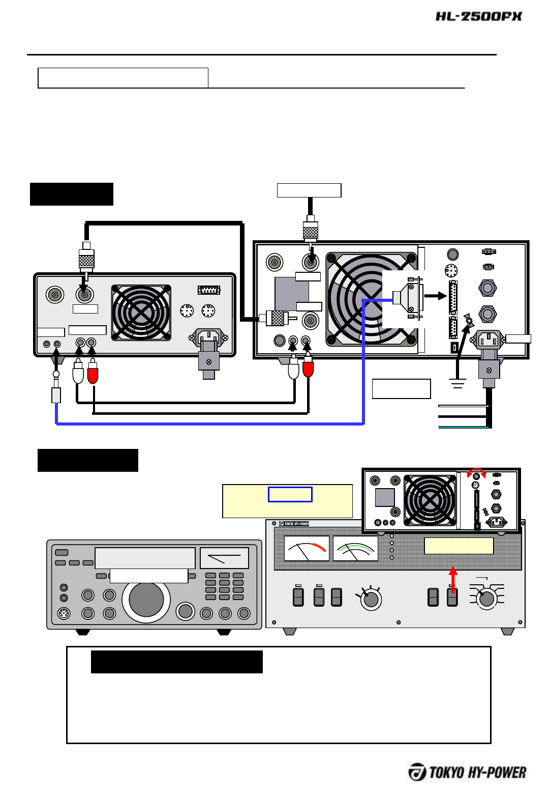
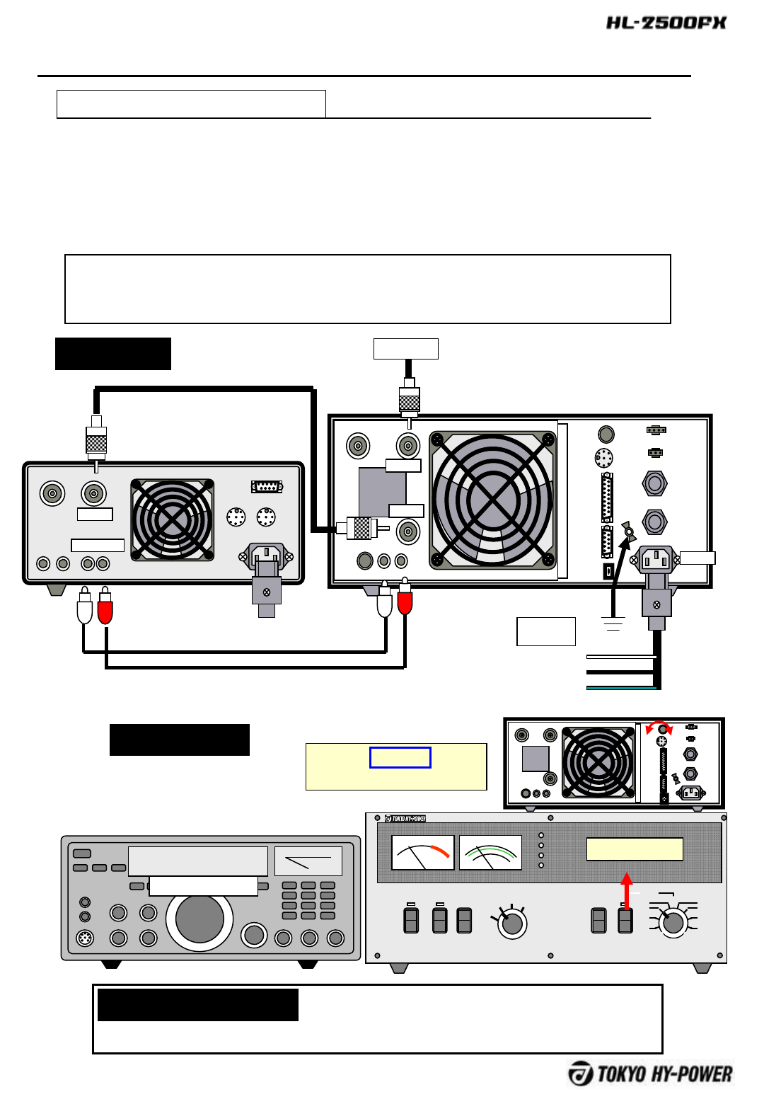
8-A Basic Connection
Following is a basic example of connection with the transceiver without using Band Data
Cable.
FUSE
FUSE
AN
T B
AN
T B
INP
UT
ALC
ADJ
A
L
C
SE
ND
TUNER
SELECT
AC IN
FUSE
FUSE
REMOTE
DC OUT
12V1A
CONT
SERIAL
USB
GN
D
Antenna
ANT A
INPUT
AC IN
ANT
AC200V
200V-
L
200V-
N
GND
white
black
green
ALC SEND
Transceiver
HL-2500FX
Caox. Cable
RCA plug cable
■SEND
SEND socket is named “RELAY”, “TX GND”, “SEND” etc depending on radio models. (Refer to user
manual of the transceiver.)
■ALC
ALC cable must be connected especially when driving the amp with high power transceiver. Otherwise
shut-down will frequently occur.
Note
-12 -
Following illustration shows a connection example with ICOM radio(CI-V) and Tokyo Hy-Power HC-
1500AT, auto antenna tuner. HC-1500AT is equipped with such an advanced function as receiving
various data (ex. Band data, SEND command etc.) from the radio and then passing them to the
linear amp. Example below utilizes this feature. (Refer to the HC-1500AT manual for the details.)
FUSE
FUSE
ANT B ANT A
INPUT
ALC ADJALC
SEND
TUNER
SELECT
AC IN
FUSE
FUSE
REMOTE
DC OUT
12V1A
CONT
SERIAL
USB
GND
ANT A
INPUT
AC IN
ANT
ALC RELAY
Transceiver
HL-2500FX
Coax cable
RCA plug cable
REMOTE
Option : ICOM cable
ANT 3 ANT 2 ANT 1
CONTYAESU
KENWOOD
I N
TRX
OUT
CIVSTBY
I N
OUT
I N
OUT
DC12V
Antenna
HC-1500AT
RCA plug cable
RCA plug cable
CI-V connection cable
Coax cable Rower cable
8-B Connection with Auto Tuner HC-1500AT
Note
HL-2500FX can be combined with our HC-1.5AT, auto tuner as well. Connect
TUNER socket of HL-2500FX to CONT’L socket of HC-1.5KAT. Interface
technology of our original design enables the joint frequency band setting.
DC power for HC-1.5KAT can also be fed from auxiliary DC supply (DC OUT
12V/2A) terminal of HL-2500FX.
However, tuner will get “THRU (By-pass) mode when 50MHz is band set, as HC-
1.5KAT has no 50MHz position.
-13 -
POWER OPER. METER
Pr
VD ALC
OFF STBY
BAND
AUTO
MAN’L
ON AIR
FAN
ID
PROT
Pf/kW
HF SOLID STATE LINEAR AMPLIFIER HL-
2500FX
MAN’L
1.8
3.5
7
10 14
18/21
24/28
50
Pr/VD/ID/A
LC
OUTPUT
HI
LO
ANT
A
B
ID
POWER OPER. METER
Pr
VD ALC
OFF STBY
BAND
AUTO
MAN’L
ON AIR
FAN
ID
PROT
Pf/kW
HF SOLID STATE LINEAR AMPLIFIER HL-
2500FX
MAN’L
1.8
3.5
7
10 14
18/21
24/28
50
Pr/VD/ID/A
LC
OUTPUT
HI
LO
ANT
A
B
ID
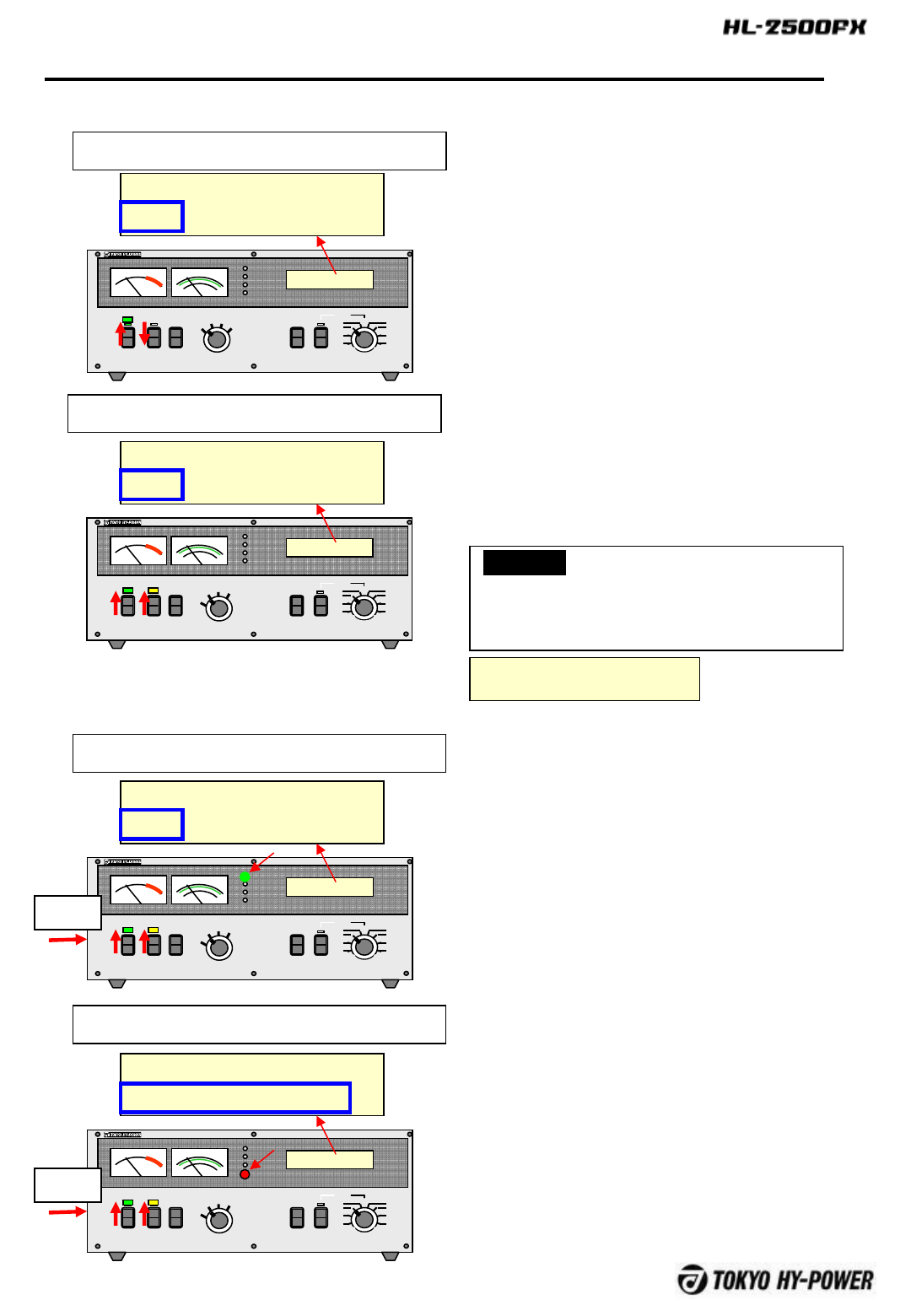
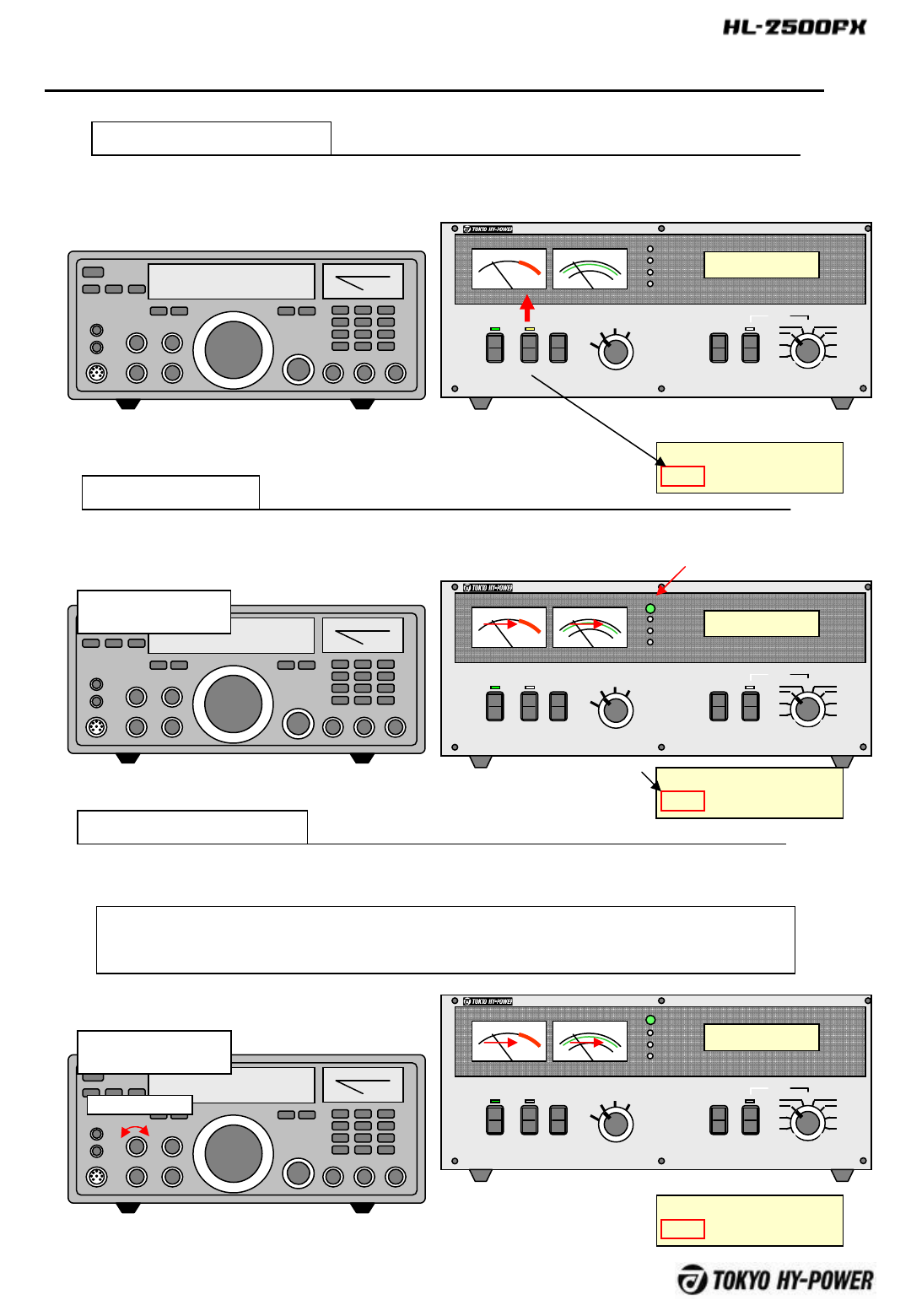
9 Operation
9-A Quick Learning / About Status Modes
1) STBY (Stand-by) Mode
1.8MHz AUT-CIV ANT-A
STBY Temp35C OUT_Hi
POWER OPER. METER
Pr
VD
ALC
OFF STBY
BAND
AUTO
MAN’L
ON AIR
FAN
ID
PROT
Pf/kW
HF SOLID STATE LINEAR AMPLIFIER HL-
2500FX
MAN’L
1.8
3.5
7
10 14
18/21
24/28
50
Pr/VD/ID/A
LC
OUTPUT
HI
LO
ANT
A
B
ID
This is a status when POWER switch is only
turned on. RF path is in THRU (or by-pass), and
DC supply to FET drain is shut down. You may
change BAND and other settings at this state.
2) OPER (Operate) Mode
1.8MHz AUT-CIV ANT-A
OPER Temp35C OUT_Hi
POWER OPER. METER
Pr
VDALC
OFF STBY
BAND
AUTO
MAN’L
ON AIR
FAN
ID
PROT
Pf/kW
HFSOLID STATE LINEAR AMPLIFIER HL-
2500FX
MAN’L
1.8
3.5
7
10 14
18/21
24/28
50
Pr/VD/ID/A
LC
OUTPUT
HI
LO
ANT
A
B
ID
This is a status when POWER switch is turned on,
and OPER/STBY switch is tuned to OPER. RF
path is in THRU, and amp is turned into ON-AIR,
as the radio’s PTT is switched on. You may change
BAND setting at this state.
3) ON-AIR(On-Air) Mode
1.8MHz AUT-CIV ANT-A
ONAR Temp35C OUT_Hi
This is a status when transceiver’s PTT is switched
on, while POWER is turned on and OPER/STBY
switch is turned to OPER. The amp is ready to
amplify the driving signal from the transceiver.
You may not change BAND and other setting at
this state.
送信
4) PROT (Protection) Mode
1.8MHz AUT-CIV ANT-A
PROT Over Heat
This is a status when PROTECTION circuit has
tripped to shut off the amplifier. RF path becomes
THRU, and internal circuitry may be shut down
according to kinds of protections. Detailed
explanation will follow.
送信
CAUTION
For your safety, the amp can not start up, if
POWER switch is at OPER.Display below will
appear.
PSE STBY OPERSW!
Turn to STBY once and turn to OPER again
for reset.
There are four operation status modes of STBY, OPER, ON-
AIR, and PROT.
-14 -
9-B Quick Learning / About Basic Signs On LCD and LED Lamps
1) CB Band Inhibit
The amp will shut down the transmission when
driving signal of 26,000 through 27,999 (CB
band) is detected due to FCC rule. When
combining with ICOM and Kenwood radios,
frequency data of operation is passed to CPU,
even at RX state, to prohibit the transmission.
EXCDMHz Is signed on LCD. (Freq. exceeded)
EXCDMHz AUT-CIV ANT-A
STBY Temp35C OUT_Hi
With ICOM, KENWOOD
28 MHz AUT-YAE ANT-A
PROT INHIBIT FREQ
With YAESU, Manual Band Set, Frequency Count Band Set
2) OPER. MODE Switch
The amp will be shut down, if POWER switch
is turned on, while OPER/STBY is set at
OPER. PSE STBY OPERSW! To reset,
switch OPER. off and on. This is to avoid
unintended sudden transmission, for your
safety
PSE STBY OPERSW!
LCD message
4) ID Lamp
IDlamp lights when FET drain currents
exceeds 55A, and is a kind of peak current
indicator. It is not a problem, if it lights only at
avoice peak (SSB).
ON AIR
FAN
ID
PROT
5) FAN Lamp
The cooling speed changes in proportion to
the variation of internal temperature. As the
ONAIR time gets longer , It is normal if fan
noise sounds louder and FAN lamp to light
brighter.
ON AIR
FAN
ID
PROT
3) TRACK Sign
3.5 MHz AUT-CIV ANT-A
TRCK Temp35C OUT_Hi
TRACK (Tracking) sign will appear, when the
BAND changes , for a short period of 0.2 sec.
This indicates that band frequency data is
being sent over to combined auto tuner.
When with Yaesu Radio, and with manual band
set and freq. count band set methods, the amp
transmission will be shut down when at TX
PROT INHIBIT FREQ will appear on LCD.
EEE
E
-15 -
POWER OPER. METER
Pr
VD ALC
OFF STBY
BAND
AUTO
MAN’L
ON AIR
FAN
ID
PROT
Pf/kW
HF SOLID STATE LINEAR AMPLIFIER HL-2500FX
MAN’L
1.8
3.5
7
10 14
18/21
24/28
50
Pr/VD/ID/ALC
OUTPUT
HI
LO
ANT
A
B
ID
POWER OPER. METER
Pr
VD ALC
OFF STBY
BAND
AUTO
MAN’L
ONAIR
FAN
ID
PROT
Pf/kW
HF SOLID STATE LINEAR AMPLIFIER HL-2500FX
MAN’L
1.8
3.5
7
10 14
18/21
24/28
50
Pr/VD/ID/ALC
OUTPUT
HI
LO
ANT
A
B
ID
9-C Quick Learning / About TX Trial
We recommend for you to run a trial operation, at first, under the Manual Band Set mode (without
band data cable connected to radio). With this trial, you can check if antenna, cables, and AC
power line are in a proper condition. In case you encounter any trouble under Auto Band Set
connection, later, you could return to this trial mode to see where the cause of trouble is.
Front Panel
・POWER=OFF ・OPER=OFF (STBY)
・OUTPUT=HI ・BAND=MANU‘L
・(Others=Any as needed)
Rear Panel
・ALC=C.C.W (Fully counter clock-wise)
・Select=Any position
Any position
FUSE
FUSE
ANT A ANT B
INPUT
ALC ADJ ALC SEND
TUNER
SELECT
AC IN
FUSE
FUSE
REMOTE
DCOUT
12V1 A
CONT
SERIAL
USB
GND
Turn the POWER on and the amp will start to execute initial self-check, Following messages will
appear on LCD until status reaches normal operation mode.
TOKYO HY-POWER
HL-2500FX V1.00
PLEASE WAIT
CHECKING CONDITIONS
ACV is 198V Normal MODE
Complete Initial Set-Up
1sec
1sec
1sec 1.8MHz Manual ANT-A
STBY Temp35C OUT Hi
Initial Sign
Checking
Checking Over
Operation Ready
After turning POWER switch on, MPU
chip will check to see if AC line voltage is
usable for the amplifier.
NOTE
1) Setting Before Power ON
2) Powering ON
Signs
Transceiver
・Mode=CW (or RTTY)
・RF POWER LEVEL=Minimal
-16 -
POWER OPER. METER
Pr
VD ALC
OFF STBY
BAND
AUTO
MAN’L
ON AIR
FAN
ID
PROT
Pf/kW
HFSOLID STATE LINEAR AMPLIFIER HL-2500FX
MAN’L
1.8
3.5
7
1014
18/21
24/28
50
Pr/VD/ID/ALC
OUTPUT
HI
LO
ANT
A
B
ID
Set the freq. BAND as desired for both transceiver and HL-2500FX.
(Ex.: 14MHz)
3)Band Setting
14MHz
設定
9-C Quick Learning / About TX Trial
NOTICE
When the BAND switch is turned under Man’l Set mode, selected BAND will shift as follows:
・If turned clock-wise, BAND will shift in the order of 14⇒21⇒28⇒50MHz.
・And if BAND is turned back, counter clock-wise, BAND will shift in the order of 50⇒24⇒18⇒14MHz.
BAND MAN’L
1.8
3.5
7
10 14
18/21
24/28
50
C.W.
1.8MHz
↓
3.5MHz
↓
7MHz
↓
10MHz
↓
14MHz
↓
21MHz
↓
28MHz
↓
50MHz
BAND MAN’L
1.8
3.5
7
10 14
18/21
24/28
50
C.C.W.
50MHz
↓
24MHz
↓
18MHz
↓
14MHz
↓
10MHz
↓
7MHz
↓
3.5MHz
↓
1.8MHz
If you are shifting up from 14
to 18, you have to turn to
24/28 once, and then turn
back to 18/21.
BAND MAN’L
1.8
3.5
7
10 14
18/21
24/28
50
BAND MAN’L
1.8
3.5
7
10 14
18/21
24/28
50
BAND MAN’L
1.8
3.5
7
10 14
18/21
24/28
50
Example
14 MHz Manual ANT-A
STBY Temp35C OUT Hi
-17 -
POWER OPER. METER
Pr
VD ALC
OFF STBY
BAND
AUTO
MAN’L
ON AIR
FAN
ID
PROT
Pf/kW
HF SOLID STATE LINEAR AMPLIFIER HL-2500FX
MAN’L
1.8
3.5
7
10 14
18/21
24/28
50
Pr/VD/ID/ALC
OUTPUT
HI
LO
ANT
A
B
ID
POWER OPER. METER
Pr
VD ALC
OFF STBY
BAND
AUTO
MAN’L
ONAIR
FAN
ID
PROT
Pf/kW
HFSOLID STATE LINEAR AMPLIFIER HL-2500FX
MAN’L
1.8
3.5
7
10 14
18/21
24/28
50
Pr/VD/ID/ALC
OUTPUT
HI
LO
ANT
A
B
ID
POWER OPER. METER
Pr
VDALC
OFF STBY
BAND
AUTO
MAN’L
ON AIR
FAN
ID
PROT
Pf/kW
HF SOLID STATE LINEAR AMPLIFIER HL-2500FX
MAN’L
1.8
3.5
7
1014
18/21
24/28
50
Pr/VD/ID/ALC
OUTPUT
HI
LO
ANT
A
B
ID
4) Switching to OPER
9-C Quick Learning / About TX Trial
14 MHz Manual ANT-A
OPER Temp35C OUT Hi
At OPER. (Operate Mode) status, the amp is ready to run together with combined transceiver.
5) Transmitting
14 MHz Manual ANT-A
ONAR Temp35C OUT Hi
Key (RTT) the transceiver with CW (or RTTY) carrier. The amp is driven to transmit.
CW (or RTTY)
6) Increasing Output
14 MHz Manual ANT-A
ONAR Temp35C OUT Hi
Adjusting the knob of transceiver ‘s RF LEVEL, increase output level to desired value.
(1,500W is maximum limit on HF, and 1,000W on 50MHz.
CW (or RTTY)
Output Level
Observe reflection from antenna and RFI (interference) to nearby home appliance.
Insert multiple number of clamp-on ferrite cores respectively to every coax cable s as well as
various control and grounding cables around the amp and the transceiver.
-18 -
9-C Quick Learning / About ALC Adjustment
7) ALC Adjustment
ALC helps the amp keep its output power at desired level. ALC is effective to avoid overdriving of
the amp, especially when high power transceiver is combined.
When adjusting ALC, use a dummy load of 2kW capacity, and /or a good antenna with SWR of
1:1 or less.
①“ALC ADJ” pot should be, at first, turned fully counter clock-wise.
②Select desired freq. band and CW (or RTTY) mode.
③Increase the driving power from the radio so that required output power is achieved from the
amp.
④Carefully increase further the drive until five to ten percent increase is obtained for output.
⑤Turn “ALC ADJ” pot clock-wise carefully so that output gradually decreases, to reach desired
level.
(For more details, see “Hints and Tips of ALC, www.tokyohypower.com)
FUSE
FUSE
ANT A ANT B
INPUT
ALC
SEND
TUNER
SELECT
ACIN
FUSE
FUSE
REMOTE
DCOUT
12V1A
CONT
SERIAL
USB
GND
ALC ADJ
-19 -
POWER OPER. METER
Pr
VD ALC
OFF STBY
BAND
AUTO
MAN’L
ON AIR
FAN
ID
PROT
Pf/kW
HF SOLID STATE LINEAR AMPLIFIER HL-2500FX
MAN’L
1.8
3.5
7
10 14
18/21
24/28
50
Pr/VD/ID/ALC
OUTPUT
HI
LO
ANT
A
B
ID
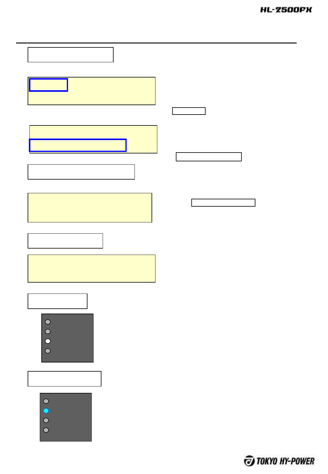
10 Operation / Setting
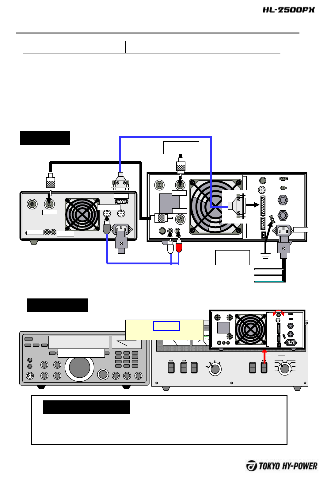
10-A With ICOM (CI-V)
Connect twin RCA plug cable (included in the package), and optional ICOM band
data cable as shown in the figure below.
Set AUTO/MAN’L switch to AUTO position and select ICOM with SELECT switch
located on the rear panel. AUTO-CIV will be displayed on LCD panel.
Set the CI-V menu of ICOM radio as shown below, and HL-2500FX will follow the
band of ICOM radio.
FUSE
FUSE
ANT A ANT B
INPUT
ALC ADJ ALC SEND
TUNER
SELECT
AC IN
FUSE
FUSE
REMOTE
DCOUT
12V1 A
CONT
SERIAL
USB
GND
14 MHz AUT-CIV ANT-A
STBY Temp35C OUT Hi
ICOM
CI-V BAUD RATE: 9600 [bps]
CI-V ADDRESS: 5Ch
CI-V Transceiver: ON
CI-V with IC-731: OFF
※Refer to ICOM’s instruction manual for CI-V details.
Setting of ICOM CI-V Menu
FUSE
FUSE
ANT A ANT A
INPUT
ALC ADJALC
SEND
TUNER
SELECT
AC IN
FUSE
FUSE
REMOTE
DC OUT
12V1A
CONT
SERIAL
USB
GND
To Antenna
ANT B
INPUT
AC IN
ANT
AC200V
Single Phase
200V-L
200V-N
GND
White
Black
Green
ALC RELAY
ICOM Transceiver
HL-2500FX
Coax Cable
RCS plug cable
REMOTE
(Option) ICOM Band Cable
Connection
Switch Setting
-20 -
POWER OPER. METER
Pr
VD ALC
OFF STBY
BAND
AUTO
MAN’L
ON AIR
FAN
ID
PROT
Pf/kW
HF SOLID STATE LINEAR AMPLIFIER HL-2500FX
MAN’L
1.8
3.5
7
10 14
18/21
24/28
50
Pr/VD/ID/ALC
OUTPUT
HI
LO
ANT
A
B
ID
10 Operation / Setting
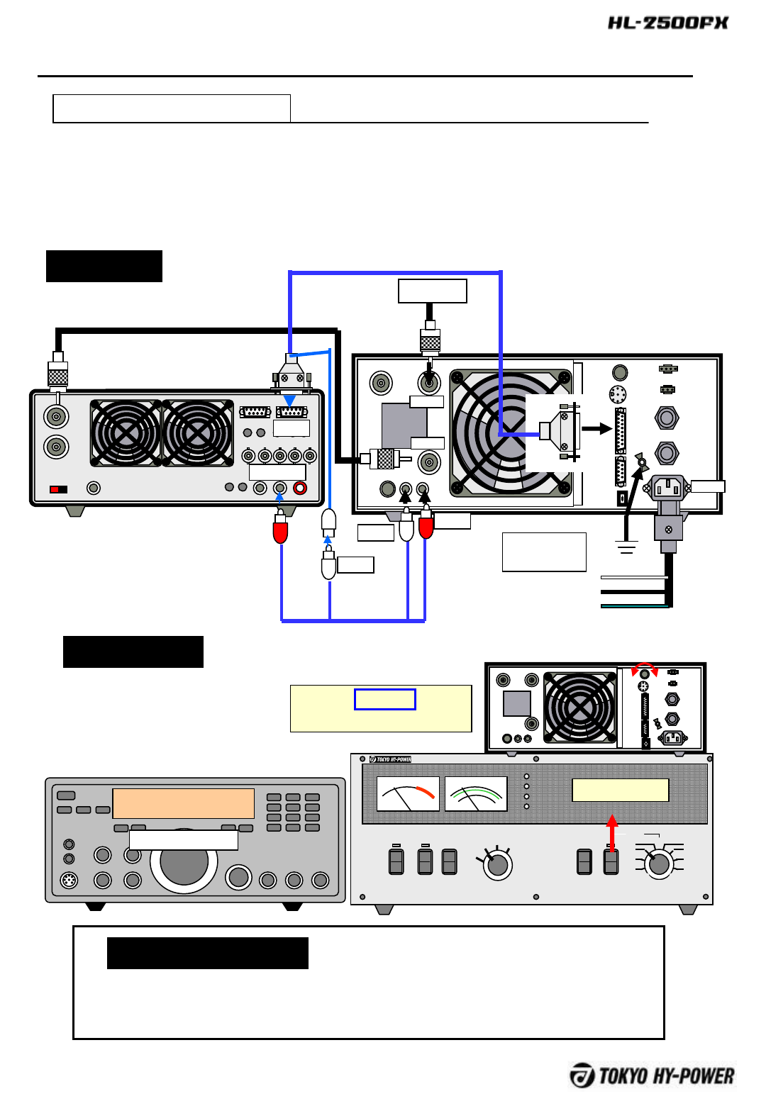
10-B With YAESU
Connect twin RCA plug cable (included in the package) and optional YAESU band data
cable as shown in the figure below.
Set AUTO/MAN’L switch to AUTO position and select YAESU with SELECT switch located
on the rear panel. AUT-YAE will be displayed on LCD panel , and HL-2500FX will follow the
band of Yaesu radio.
FUSE
FUSE
ANT A ANT B
INPUT
ALC ADJ ALC SEND
TUNER
SELECT
ACIN
FUSE
FUSE
REMOTE
DC OUT
12V1A
CONT
SERIAL
USB
GND
14 MHz AUT-YAE ANT-A
STBY Temp35C OUT Hi
YAESU
Some Yaesu models require initial settings for maximum output and T/R relay (TX
GND) output.
Refer to the user manual for details.
Setting of Transceiver
Connection
Switch Setting
FUSE
FUSE
ANT B ANT A
INPUT
ALC ADJALC
SEND
TUNER
SELECT
AC IN
FUSE
FUSE
REMOTE
DC OUT
12V1A
CONT
SERIAL
USB
GND
To Antenna
ANT A
INPUT
AC IN
ANT
AC200V
Single Phase
200V-L
200V-N
GND
White
Black
Green
TXGND
YAESU
HL-2500FX
Coax Cable
RCA plug cable
YAESU Band Data Cable
EXT_ALC
BAND DATA
-21 -
POWER OPER. METER
Pr
VD ALC
OFF STBY
BAND
AUTO
MAN’L
ON AIR
FAN
ID
PROT
Pf/kW
HF SOLID STATE LINEAR AMPLIFIER HL-2500FX
MAN’L
1.8
3.5
7
10 14
18/21
24/28
50
Pr/VD/ID/ALC
OUTPUT
HI
LO
ANT
A
B
ID
10 Operation / Setting
10-C With KENWOOD
Prepare a control cable for PTT(SEND) and ALC. One end should be DIN plug for
REMOTE of Kenwood radio. The other end should be two RCA jacks of the amp.
(Refer to Kenwood manual for REMOTE socket pin assignment.)
Set AUTO/MAN’L switch to AUTO position and select KENWOOD with SELECT
switch located on the rear panel. AUT-KEN will be displayed on the LCD panel,
and HL-2500FX will follow the band of Kenwood radio.
FUSE
FUSE
ANT A ANT B
INPUT
ALC ADJ ALC SEND
TUNER
SELECT
AC IN
FUSE
FUSE
REMOTE
DC OUT
12V1 A
CONT
SERIAL
USB
GND
14 MHz AUT-KEN ANT-A
STBY Temp35C OUT Hi
KENWOOD
Baud Rate :9600[bps]
Stop Bit :1bit
※Refer to Kenwood manual for details.
Setting of Transceiver
Connection
Switch Setting
FUSE
FUSE
ANT B ANT A
INPUT
ALC ADJALC
SEND
TUNER
SELECT
AC IN
FUSE
FUSE
REMOTE
DC OUT
12V1A
CONT
SERIAL
USB
GND
To Antenna
ANT A
INPUT
AC IN
ANT
AC200V
Single Phase
200V-L
200V-N
GND
White
Black
Green
TXGND
トランシーバ
HL-2500FX
Coax Cable
RCA Plug Cable (ALC/SEND)
(Not included)
Band Data Cable
EXT_ALC
REMOTE
COM
-22 -
POWER OPER. METER
Pr
VD ALC
OFF STBY
BAND
AUTO
MAN’L
ON AIR
FAN
ID
PROT
Pf/kW
HF SOLID STATE LINEAR AMPLIFIER HL-2500FX
MAN’L
1.8
3.5
7
10 14
18/21
24/28
50
Pr/VD/ID/ALC
OUTPUT
HI
LO
ANT
A
B
ID
10 Operation / Setting
10-D With ELECRAFT(K3)
Connect included twin RCA plug cable and optional Elecraft band data cable as
shown in the figure below.
Set AUTO/MAN’L switch to AUTO position and select ELECRAFT with SELECT
switch located on the rear panel.
AUT-ELC will be displayed on LCD panel and HL-2500FX will follow the band of
K3 radio.
FUSE
FUSE
ANT A ANT B
INPUT
ALC ADJ ALC SEND
TUNER
SELECT
ACIN
FUSE
FUSE
REMOTE
DC OUT
12V1A
CONT
SERIAL
USB
GND
14 MHz AUT-ELC ANT-A
STBY Temp35C OUT Hi
ELECRAFT(K3)
Setting of “DONFIG menu” is required for K3transceiver.
(Refer to K3 manual for details).
Setting of Transceiver
Connection
Switch Setting
FUSE
FUSE
ANT B ANT A
INPUT
ALC ADJALC
SEND
TUNER
SELECT
AC IN
FUSE
FUSE
REMOTE
DC OUT
12V1A
CONT
SERIAL
USB
GND
To Antenna
ANT A
INPUT
AC IN
AC200V
Single Phase
200V-L
200V-N
GND
White
Black
Green
ELECRAFT(K3)
HL-2500FX
Coax Cable
RCA Plug Cable
Band Data Cable
KEY OUT
ALC
EBC-2.4K/K3
SEND
ALC
ACC
-23 -
POWER OPER. METER
Pr
VD ALC
OFF STBY
BAND
AUTO
MAN’L
ON AIR
FAN
ID
PROT
Pf/kW
HF SOLID STATE LINEAR AMPLIFIER HL-2500FX
MAN’L
1.8
3.5
7
10 14
18/21
24/28
50
Pr/VD/ID/ALC
OUTPUT
HI
LO
ANT
A
B
ID
10 Operation / Setting
10-E Frequency Count Method
When there is no way of auto band-set connection between the transceiver and the amplifier
and or when it is desired to make mutual band connection simple, auto band-set-operation is
feasible utilizing the frequency counting feature built in this amplifier.
Set AUTO/MAN’L switch to AUT-FRQ with SELECT switch located on the rear panel.
AUT-FRQ will be displayed on LCD panel and the amp will set the band automatically reading
the frequency of driving signal . If the transceiver is keyed, the amplifier will set the operating
band automatically by reading the frequency of driving signal.
CAUTION
There is a time delay of 20 milli-sec from RX to TX state change under this method. Full
break-in CW is not available with this method, for this reason.
FUSE
FUSE
ANT A ANT B
INPUT
ALC ADJ ALC SEND
TUNER
SELECT
AC IN
FUSE
FUSE
REMOTE
DC OUT
12V1 A
CONT
SERIAL
USB
GND
14 MHz AUT-FRQ ANT-A
STBY Temp35C OUT Hi
ICOM
There is nothing required in particular.
Setting of Transceiver
Connection
Switch Setting
FUSE
FUSE
AN
T B
AN
T A
INP
UT
ALC
ADJ
A
L
C
SE
ND
TUNER
SELECT
AC IN
FUSE
FUSE
REMOTE
DC OUT
12V1A
CONT
SERIAL
USB
GN
D
To Antenna
ANT A
INPUT
AC IN
ANT
AC200V
200V-L
200V-N
GND
ALC SEND
Transceiver
HL-2500FX
Coax Cable
RCA Plug Cable White
Black
Green
-24 -
11 Protection Circuit
11-A Interlock Protection
1)Cover Interlock
When the top cover is removed, cover switch is activated to shut down AC power line.
(POWER Lamp, LCD panel, cooling fan are all turned off.)
2) Temperature Interlock
When the internal temperature of the amp reaches 90℃,AC power line is shut down.
(POWER Lamp, LCD panel, cooling fan are all turned off.)
In case all the lamps go off suddenly while transmitting , stop the transmission, unplug AC
cord, and wait for five minutes.
Check if AC main fuses are blown, or if the temp. inter-lock has been activated.
★“Interlock” is built in for the safety of operator, avoiding the unexpected accidents from
electric and thermal shocks.
Sign Status
All power shut down.
No sign. Main DC P. Supply (Vdd) Shut down
AC Magnet Relay Shut down
RF path Shut down
Fan Control Shut down
Reset
①Fix top cover securely
②Cool off the amplifier sufficiently
POWER OPER. METER
Pr
VD ALC
OFF STBY
BAND
AUTO
MAN’L
ONAIR
FAN
ID
PROT
Pf/kW
HF SOLID STATE LINEAR AMPLIFIER HL-2500FX
MAN’L
1.8
3.5
7
10 14
18/21
24/28
50
Pr/VD/ID/ALC
OUTPUT
HI
LO
ANT
A
B
ID
Front Side
Rear Side
Power Supply
Interlock
Switch
REMARKS Location of Interlock Switch
The amp temperature is normally checked by thermal sensor and microprocessor.
“FAULT” temp protection is usually switched on in prior to Temp. Interlock to turn on, the
amp may have been heated by other heat source and or microprocessor is in failure.
-25 -
POWER OPER. METER
Pr
VDALC
OFF STBY
BAND
AUTO
MAN’L
ONAIR
FAN
ID
PROT
Pf/kW
HF SOLID STATE LINEAR AMPLIFIER HL-
2500FX
MAN’L
1.8
3.5
7
10 14
18/21
24/28
50
Pr/VD/ID/A
LC
OUTPUT
HI
LO
ANT
A
B
ID
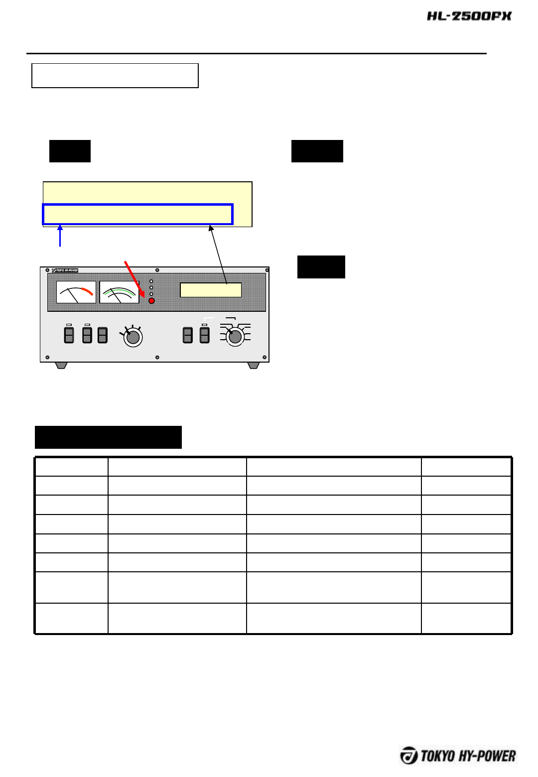
11-B Fault Protection
1.8MHz AUT-CIV ANT-A
PROT OVER TEMP
Prot. LCD Sign Description Remedy
Over Heat FAULT OVER TEMP Heat sink temp reached 95℃ Cool off to reset
Fan Faulty FAULT FAN FAIL FAN faulty or speed too low Repair at factory
AC Line High FAULT OVER LINE VOLT AC line exceeded 250V Check AC line
AC Line Low FAULT UNDER LINE VOLT AC line fell to 85V or lower Check AC line
Fuse Blown FAULT FUSE BLOW Internal fuse blown Refer to Pxxx
Main P.S.
Faulty
FAULT DC SUPPLY OUT Output of main DC P.S. (Vdd) faulty Repair at factory
Main P.S.
Faulty
FAULT DC SUPPLY Primary side of main DC P.S. faulty Repair at factory
FAULT PROTECTION
Sign Status
PROT lamp glows.
Message is displayed
Main DC P. Supply Shut Down
AC Magnet Relay Shut Down
RF Path Thru
Fan Control ON
Reset
Set OPER/STBY switch to STAND-BY
position, and turn POWER switch off and
on.
List of Fault Protection
Fault Protection is built in to avoid the damage to the amp due to the severe cause of fault within the
amplifier or on the AC power line.
Protection Sign
-26 -
11 Protection Circuit
1.8MHz AUT-CIV ANT-A
PROT CROWBAR
Protection Sign
11-C Protection / Slight Fault
Sign Status
PROT lamp glows.
Message is displayed
Main DC P. Supply (Vdd))On
AC Magnet Relay ON
RF Path Thru
FAN・Control Circuit ON
Reset
Switch “OPERATE/STBY” off and on.
List of PROT
Prot. LCD Sign Description Re-adjust ALC
Over Out
put Power
PROT OVER POWER RF output power exceeded 1,500W Re-adjust ALC
Inhibit Freq. PROT INHIBIT FREQ CB band freq.(26,000~27,999MHz)
detected
Check x-ceiver
Reflected
Power
PROT OVER Pr Power reflection from antenna
exceeded 150W
Check antenna
Over
Current
PROT OVER CURRENT FET drain current (Id) exceeded 70A Check antenna
Re-adjust ALC
Over
Dissipation
PROT OVER Ploss FET drain dissipation (Pd) exceeded
2,000W
Tj Over PROT OVER Tj FET junction temperature exceeded
190℃
Over Drive PROT OVER DRIVE RF drive power exceeded 150W Readjust ALC,
decrease RF drive
from X-ceiverf
Unbalance PROT COMB HEAT PA combiner temperature exceeded
70℃
Check antenna
SWR
Contact factory
*Crowbar PROT CROWBAR Crowbar prot. Circuit switched on See below
Band Mis-
set
PROT BAND MIS-SET Band set incorrect., PA failed Check band setting
Contact factory
POWER OPER. METER
Pr
VD ALC
OFF STBY
BAND
AUTO
MAN’L
ON AIR
FAN
ID
PROT
Pf/kW
HF SOLID STATE LINEAR AMPLIFIER HL-
2500FX
MAN’L
1.8
3.5
7
10 14
18/21
24/28
50
Pr/VD/ID/A
LC
OUTPUT
HI
LO
ANT
A
B
ID
Another group of protection circuits are provided to shut down the transmission when the other faults
occur within the amp.

-27 -
11 Protection Circuit
11-C Protection / Slight Fault
Crowbar
When the FET drain current and reflected power from antenna significantly exceed the limit, crowbar
circuit trips instantly to protect valuable FET finals, without waiting for the response from the
microprocessor. It blanks the RF drive for 100ms. During this time period, microprocessor detects the
abnormal states to issue shut down command under “PROT CROWBER”.
POWER OPER. METER
Pr
VD ALC
OFF STBY
BAND
AUTO
MAN’L
ON AIR
FAN
ID
PROT
Pf/kW
HF SOLID STATE LINEAR AMPLIFIER HL-
2500FX
MAN’L
1.8
3.5
7
10 14
18/21
24/28
50
Pr/VD/ID/A
LC
OUTPUT
HI
LO
ANT
A
B
ID
11 Protection Circuit
If slight failure occur such as “over current”, for example, while working under OUT=Hi mode
(High output mode), the amp is not necessarily shut down, but enters into reduced power
operation mode
1.8MHz AUT-CIV ANT-A
ONAR Temp35C OUT_LoLIM
Protection LCD Sign Description Remarks
Sight Over Current
OUT: LoLim
Drain current (Id)
exceeded 55A for 60sec
When exceeding 70A, PROT shuts
down immediately
Slight Over Heat Heat sink temp. exceeded
75℃
When exceeding 95℃,FAULT PROT
shuts down
Over Dissipation Total FET drain
dissipation exceeded
2,000W
If 2,000W exceeded, even reduced
power mode, PROT shuts down
Over Tj FET junction temp (Tj)
exceeded 190℃
If Tj keeps 90℃,even with reduced
power mode, PROT shuts down
Sign Status
Following message displayed
Main DC P. Supply (Vdd))Low Voltage Applied
AC Magnet Relay ON
RF path ON (Amplifying)
Output Setting) Lo(Low Vd)
FAN, control circuit ON
Reset
Release PTT (to RX) once, and key (to
TX) again.
List of Protection
11-D Protection / Reduced Power
Operation
-29 -
12 Technic al Inform ation about Va rious Connectors
Pin # Signal Description Remarks
1 +12V Auxiliary DC P. Supply +12V0.1A Never short
9 +5V Auxiliary DC P. Supply +5V0.1A Never short
2 RXD Serial Comm. Port (RX) For EIA232_TRX
10 TXD Serial Comm. Port (TX) For EIA232_TRX
3 BDY0 YAESU Band Data Input 0bit With pull-up resistor
11 BDY1 YAESU Band Data Input 1bit With pull-up resistor
4 BDY2 YAESU Band Data Input 2bit With pull-up resistor
12 BDY3 YAESU Band Data Input 3 bit With pull-up resistor
5 GND Signal Ground
13 AN-IC ICOM Analog Freq. Info. IN
6 AN-IC-G ICOM Analog Freq. Info. Gnd
14 T/R T/R(SEND) IN Connector in parallel
with “SEND”
7 GND Signal Ground
15 CIV-T ICOMCI-V TX Port
8 CIV-R ICOMCI-V RX Port
12-A CONT Connector (Control)
Pin Assignment
12-B TUNER Connector
For connector to THP HC-1.5KAT, and HC-1500AT tuners. (DIN
7pin Connector, Female, Hoshiden TCS4470-0140577)
Various control signals are concentrated in this connector. (D-SUB 15pin
Connector, Female)
Pin # Signal Description Remarks
2 GND Signal Ground
4 EVENT Event IN (FREQ request
signal)
7 FREQ Freq. Information OUT FREQOUT=MHz/1000
1・3・5・6 No Connection
-30 -
Pin # Signal Description Remarks
2 RD RX Signal For straight cable
3 TD TX Signal For straight cable
5 GND Signal Ground
Others No Connection
12-C CONT Connect (Control)
Pin Assignment
Serial connector for utility use (D-SUB 9pin Connector, Female)
12 Technical Information About Various Connectors
This connector is for utility use, and can not be connected to the transceiver. It is
adifferent one from TD/RD of CONT connector.
Pin # Signal Description Remarks
1 DC12V Auxiliary DC P.S.12V2A
2 No connection
3 GND Return
12-D DC12V Connector
Pin Assignment
Auxiliary DC power supply of DC12V2A capacity. Suitable for feeding auto tuner.
(Type SMPo3V by Nichiatsu)
Note
-31 -
Pin # Signal Description Remarks
1 WAKE-UP+ Start up voltage IN+Start up when
DC12V applied.
(DC12V100mA)
2 WAKE-UP- Start up voltage IN-
3
OPER_EXT External OPER Input To enter “Operate”
when pin 3 grounded
(15mA). 5V, when
Open
4 GND Signal GND
12-E REMOTE Connector
Pin Assignment
For controlling the amplifier from the remote location. (Type SMP04V by Nichiatsu)
Note : Please refer to “Remote Controlled Operation” Section.
Note
12 Technical Information About Various Connectors
-32 -
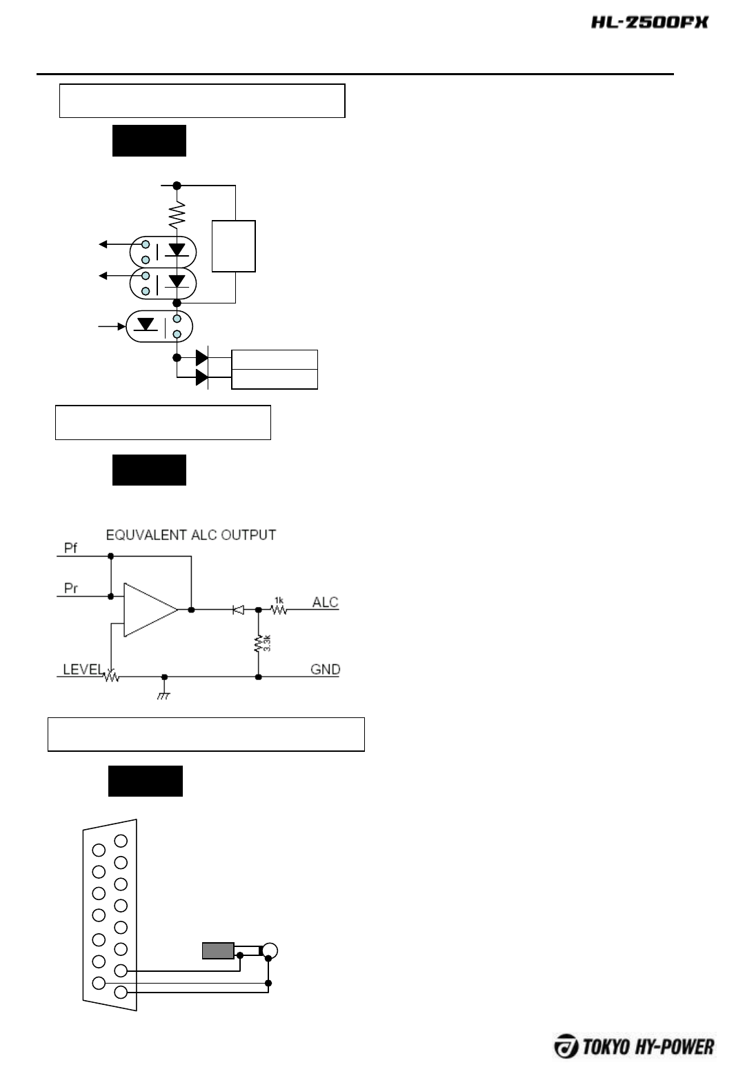
12-F About SEND Interface
Circuit
TX/RX switch terminal (SEND socket) is
controlled through photo-MOS relay rather than
thru direct relay switching. Open voltage is
+12V, and draws 10ma when grounded. When
PROTECTION trips, photo-MOA relay for TX
Inhibit becomes open and TX is shut down
From TX
inhibit
To relay
To control
circuit
+12V
SEND(RCA)
CONT14pin
1kΩ
12-G ALC Interface
When the sum of forward output power (voltage) and
reflected output power (voltage) exceeds the
programmed ALC level, negative voltage is produced
at ALC terminal.
ALC circuit consists of an Ope-amp, and it is
preferable that input port of the transceiver for the
external ALC voltage has an input impedance of 10K
Ωminimum.
Maximum ALC output of -10V is usually produced.
Some of old fashioned radio may require higher
voltage. Built-in gain switch needs switched in that
case.
Relay
12-H About ICOM CI-V Interface
Circuit
CONT
1
2
3
4
5
6
7
8
9
10
11
12
13
14
15
3.5mmPHON
OPULG
CI-V signal lines are connected to pins 7, 8
and 15 of CONT Connector.
Circuit
12 Technical Information about Various Connectors
-33 -
9
1
2
3
4
5
6
7
8
1
2
3
4
5
6
7
8
9
10
11
12
13
14
15
1
2
3
4
5
6
7
8
9
10
11
12
13
14
15
BAND A
BAND B
BAND C
BAND D
GND
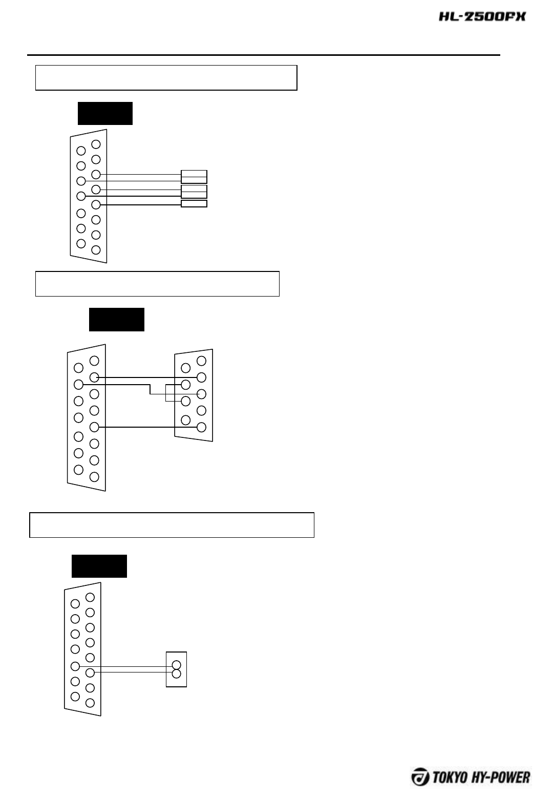
12-I About YAESU and K3 Interface
Circuit
Four bits of band data (A to D) are
connected to CONT connector as
illustrated.
This interface is used for Elecraft K3 as
well.
CONT
12-J About KENWOOD Interface
Circuit
Kenwood uses TD/RD pins of CONT
connector for EIA232C based serial
communication. Loop back wiring for
pin 7 and 8 is required at Kenwood
connector side.
1
2
3
4
5
6
7
8
9
10
11
12
13
14
15
BAND
GND
12-H ICOM(BAND VOLTAGE)Interface
Circuit
CONT
4
2
ICOM
ACC2
Connector
CONT
12 Technical Information about Various Connectors
-34 -
13 Maintenance
POWER OPER. METER
Pr
VD ALC
OFF STBY
BAND
AUTO
MAN’L
ON AIR
FAN
ID
PROT
Pf/kW
HF SOLID STATE LINEAR AMPLIFIER HL-2500FX
MAN’L
1.8
3.5
7
10 14
18/21
24/28
50
Pr/VD/ID/ALC
OUTPUT
HI
LO
ANT
A
B
ID
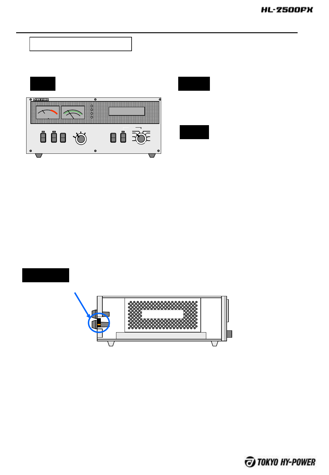
To remove the top cover, unscrew nine M3 bolts and eight M4 bolts on the
upper surface, as well as six each M3 bolts at right and left surfaces of the
cover.
Upper Surface M3x6 9(Black)
M4x8 8(Red)
Right surface
M3x6 6
Left surface
M3x6 6
13-A How to remove the top cover
Lift the cover carefully.
Widen
Widen
CAUTION
Inter-Lock switch
is located.
Inter-Lock
-35 -
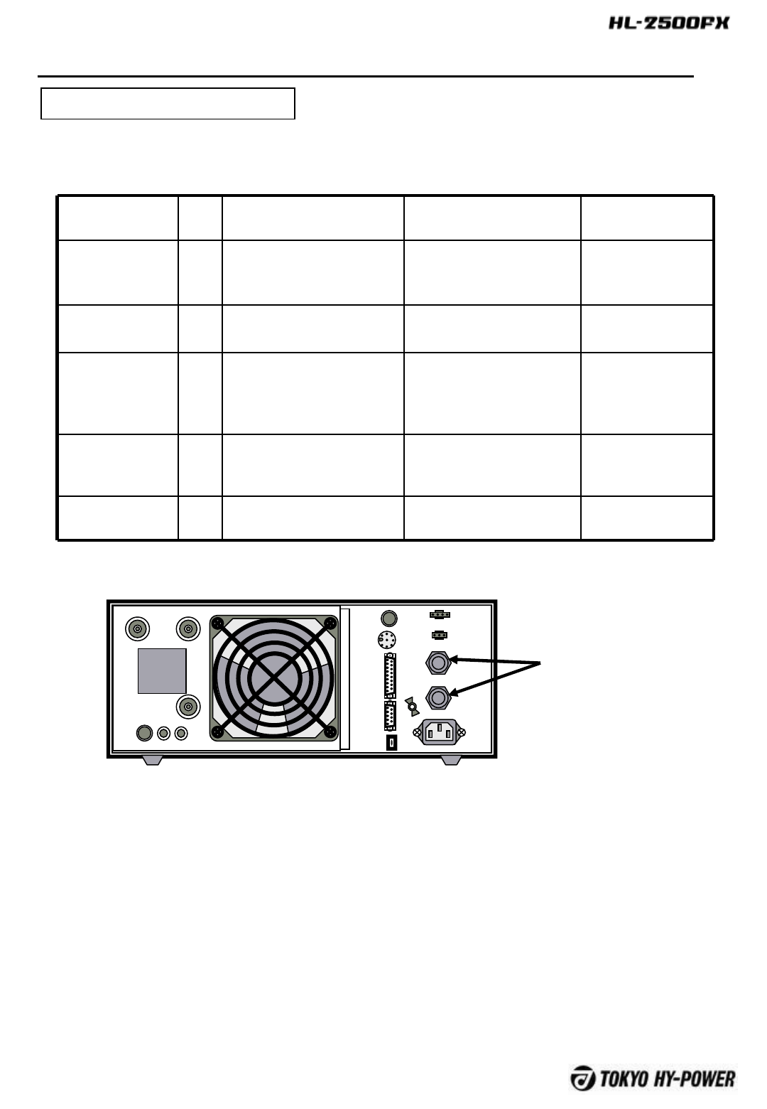
Variety of fuses are built in the amplifier. Fuses are consumption item, and may melt to blow,
astime passes by even if there is no failure in the circuit.
Fuse Name
and Location
Q’ty Specs/Rating Problem when blown Possible Cause
AC Fuse
AC Primary
Line
2 250CF6.3x32 250V20A
(Fast attack)
Do not power on Over output
Power supply
failure
PA DC Fuse
PA drain
3 #1197(Low Profile) Fuse,
58V20A
“FAULT FUSE BLOW” Over current
PA Failure
DC Fuse
Control circuit
1 LM3.2 30V3.2A by Daito
Micro Fuse
Do not power on CONT terminal
short
Control circuit
failure
DC Fuse
Auxiliary DC
P.S.
1 LM3.2 30V3.2A Daito
Micro Fuse
No12V output (External
tuner not work)
DC output
terminal short
RF Input Prot.
Fuse RF Input
1 LM1.6 30V1.6A by Daito
Micro Fuse
No RF output from amp Over drive
13-B How to replace Fuses
FUSE
FUSE
ANT A ANT B
INPUT
ALC ADJ ALC
SEND
TUNER
SELECT
AC IN
FUSE
FUSE
REMOTE
DCOUT
12V1A
CONT
SERIAL
USB
GND
AC Fuse
13 Maintenance
-36 -
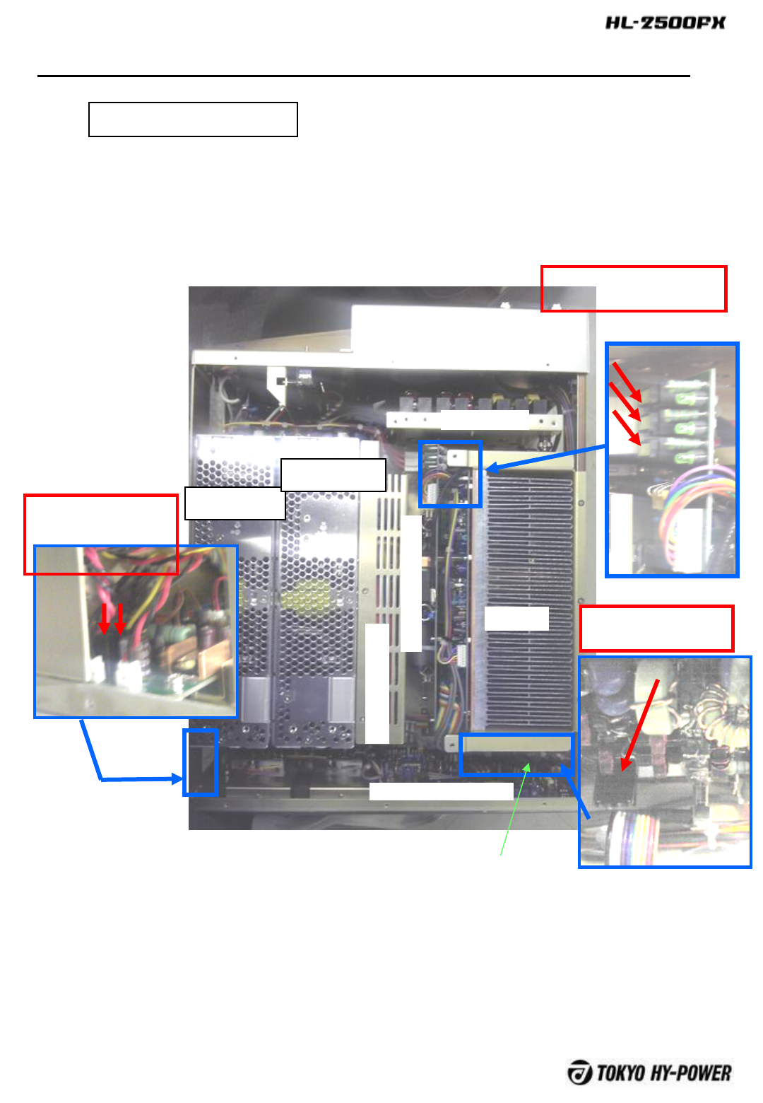
13-C Fuse Location
DC Fuse /PA FET Drain
DC58V20A(Yellow) x3
Drain Vdd P.S.
1
Drain Vdd P.S.
2
Control Circuit Board
L.P.F.
PA
RF Power Splitter
RF Power Combiner
T/R Relay Box
RF Input Prot Fuse
1.6A (Black)
DC Fuse
(Control circuit DC
3.2A (Black)
and12V DC P.S.
Control DC P.S.
13 Maintenance
-37 -
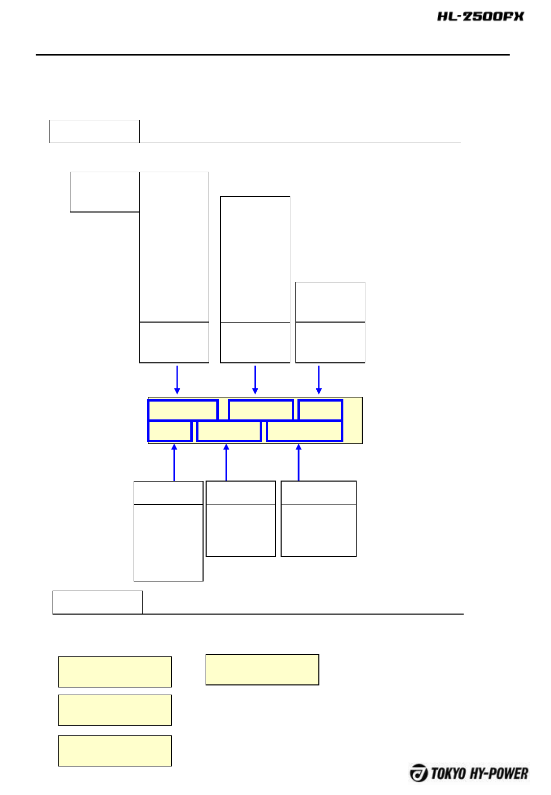
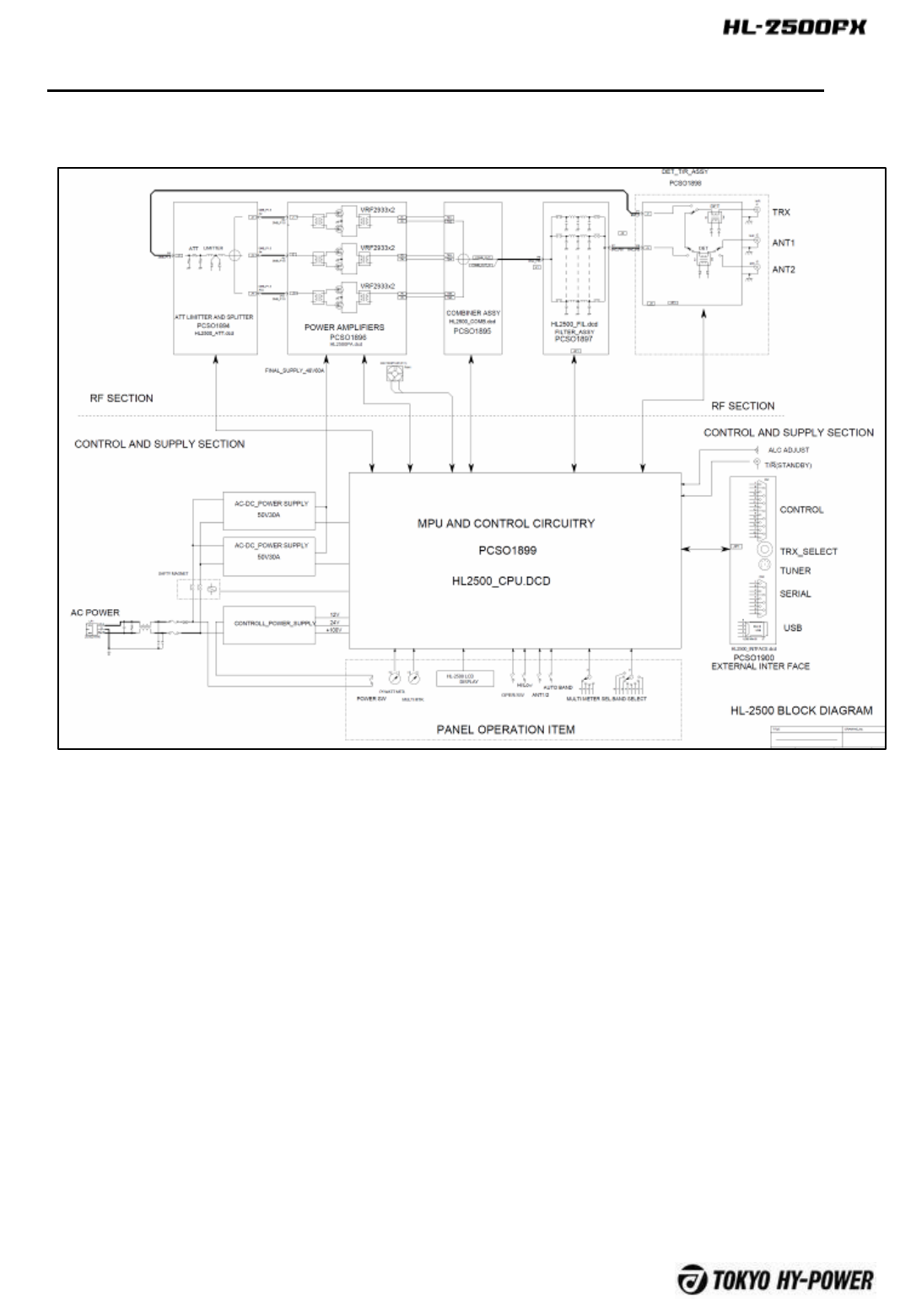
14 Block Diagram and Explanation of Major Circu itry
14-A RF Amp
Driving RF signal transmitted from the
transceiver is lead to the ATT/ Limitter board via
T/R-Assy unit, where there is 3dB attenuator as
well as RF limiter. These circuitry properly
levels the magnitude of RF signal and also
instantly shuts down the input to protect the
amplifier.
There is a three port splitter located in this
board that sprits a driving signal equally into
three components, which are then fed to final
PA module.
PA module consists of three sets of wide band
class AB1 linear amp. using THP2933 FET’s in
the push-pull form. 500W is achieved per one
basic amp. board. Then the three outputs from
the PA module is sent to the combiner unit,
where three 500W components are combined to
become 1,500W.
Operating status of three PA’s are strictly
monitored in the combiner stage with regard to
heat balancing of respective amps.
Finally 1,500W of RF output is lead to LPF (low
pass filter) unit, where harmonics and spurious
signals are reduced to FCC rules. Filtered
output signal is sent to T/R ASSY unit again and
is lead to antenna terminal by way of antenna
relay.

-38 -
14-B DC Power Supply
AC power is received at the IEC socket
intake and passes the line filter. There are
safety fuses on both lines. There are control
power supply and FET drain power supply .
Start up is usually made by turning on and off
of control power supply. DC 12V, 24V and 100V
are available when control power supply is
turned on, and are always outputted once the
POWER is turned on.
There are a magnet relay at primary side and
DC ON/OFF function at secondary side.
Depending on the operating condition, this
power supply is turned on and off through the
control circuit, and is provided in this power
supply to meet IEC61000-3-2 harmonics
regulation.
14 Block Diagram and Explanation of Major Circuitry
14-C Control Circuit
Control circuit performs various control using
micro-processor PIC18F8722 chip. Also, basic
interface meet the necessary rules and
conditions using the specialized semiconductor
devices.