Tong Lung Metal Industry PL2-BT Electronic BLE Deadbolt User Manual Manual
Tong Lung Metal Industry Co.,Ltd. Electronic BLE Deadbolt Manual
Manual
Brand: EZSET
Model: PL2-BT
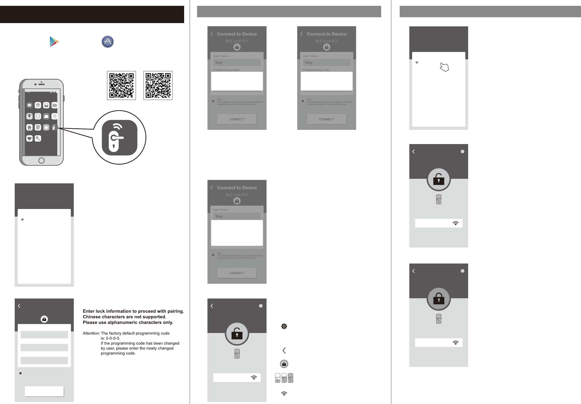
Please download “BLE Smart Lock”
on Google Play or App Store.
Once the installation is completed, turn on the device’s
Bluetooth and open “BLE Smart Lock” App to begin pairing.
Wait for the page to scan for Bluetooth locks
in range.
Locks found will be shown on screen.
Select the lock with default name of
“BLE Lock-PL1” to continue.
Note: Bluetooth scanning time may vary depending
on Android manufacturers.
Attention: “BLE Lock-PL1” shown in black font means
the unit is available.
Paired lock names will be shown in red.
The default name may vary for other product
model.
Electronic BLE Touch Deadbolt Pairing With Bluetooth Lock
Follow the tips, touch lock with mobile phone
and select “OK”.
This step calibrates the sensor proximity.
Please ensure the pairing process is done with
mobile phone as close to the lock as possible.
Failing to do so will cause sensor distance error and
increase safety detection warning area.
Bluetooth paring is completed when the lock
setting screen displays the following:
Please follow the instructions for
door handing - so that your lock
knows if it is used on a left hand or
right hand door. Then proceed with
pairing.
Attention:
When “The lock is not set” message
appears.
Motor Detect Error
Attention:
When “ ” message appears.
Bluetooth pairing must be carried out while the
lock is in unlocked state.
Please first unlock, then proceed with pairing
process.
Home
Home
Signal Strength
Lock / Unlock With Paired Mobile Phone
BLE Smart Lock
Ma il Ca le nd ar P ho to s Ca me ra
Ne wsWe at he rCl oc kMa ps
BL E
Sm ar t Lo ck
Fa vo ri te sNo te sHo me
Se tt in gsHe al th
Open BLE Smart Lock App and select paired
lock.
Attention: The working range between the lock and
your Smartphone is around 16 feet (5m).
Unlocked Icon
The GREEN (unlocked) icon means the current status
of the lock is "UNLOCKED".
Administrator Function Settings
Home Lock Name (Set by user)
Go Back
Lock / Unlock
Lock Battery Level
Bluetooth signal strength between
Smart phone and lock
Connect to Device
BLE Lock-PL1
User Name
Programming Code
Lock Name
Tony
Home
● ● ● ●
CONNECT
Note :
If the password is default value, please change the
programming code for locker before pairing.
My lock
Here are your Locks
Choose a lock to configure
Nearby locks
BLE Lock-PL1
My locks
Here are your Locks
Choose a lock to configure
Nearby locks
Home(paired)
Connect to Device
BLE Lock-PL1
User Name
Programming Code
Lock Name
Tony
Home
● ● ● ●
CONNECT
Note :
If the password is default value, please change the
programming code for locker before pairing.
The lock is not set
CONFIRM
Locked Icon
The ORANGE (locked) icon means the current status
of the lock is "LOCKED".
Connect to Device
BLE Lock-PL1
User Name
Programming Code
Lock Name
Tony
Home
● ● ● ●
CONNECT
Note :
If the password is default value, please change the
programming code for locker before pairing.
CONFIRM
Connection Note
Always make sure to stand at a close
distance from your BLE lock
CANCEL
Connect to Device
BLE Lock-PL1
User Name
Programming Code
Lock Name
Tony
Home
● ● ● ●
CONNECT
Note :
If the password is default value, please change the
programming code for locker before pairing.
Motor Detect Error
CONFIRM
Home
Home
Signal Strength
Home
Home
Signal Strength
ios app android app
Brand: EZSET
Model: PL2-BT
Safety DetectionBluetooth Authentication
12" (30cm)
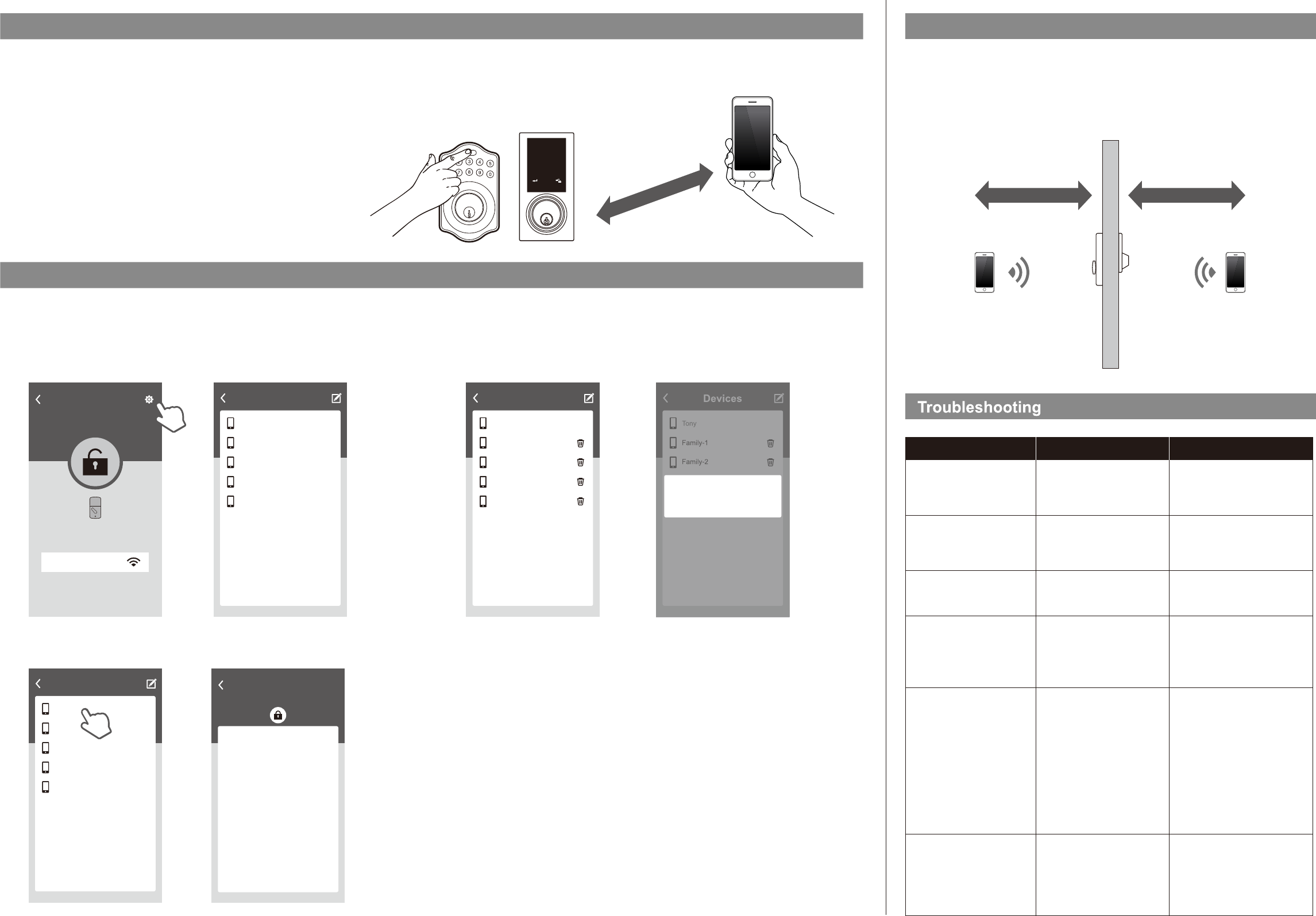
Administrator Functions
Load paired devices list
Select the Setting icon on the top right corner of the locking setting screen to view
paired Bluetooth devices.
Administrator’s name appears in red. All other users’ name appear in black.
(6 devices max, including the administrator)
Review Usage Log
Select administrator device name (in red) to review usage log.
Attention: Unlocks made with passwords will show in log as “Code”, but no date and time information will be recorded.
Devices
Tony
Family-1
Family-2
Family-3
IOS
When the smart phone is within 20" (50cm) of the lock and the connection has been established
a 10 seconds countdown will begin on the lock.
If user does not unlock within 10 seconds by pressing the “Bluetooth” button, five short beeps
will sound warning the user that currently mobile phone is within connection distance and they
should move out of the 20" (50cm) connection range.
20" (50cm)
Problem Possible Causes Actions
Unable to find locks on the
scan page.
“The lock is not set”
message appears during
pairing process.
“Motor Detect Error”
message appears during
pairing process.
“Lock Has Been Reset”
message appears when
entering Settings screen in
App.
Unable to perform one push
unlock.
(1) Bluetooth not turned on.
(2) Batteries are low or dead.
Door handing has not been
set.
Lock has not been unlocked.
(1) The lock has been reset by
other users.
(2) User has been deleted by
administrator.
(1) Mobile phone is too far
from the lock.
(2)Lock has been reset.
Mobile phone was not paired
correctly by touching the lock
during the pairing process.
(1) IOS system please manually
enable Bluetooth function.
(2) Change batteries.
(1) Please turn lock bolt to
“Unlocked” state/status, then
try the pairing process again.
(2) Please consult with the
administrator.
(1) Please make sure the mobile
phone is within 12" (30cm)of
the lock for one push unlock.
(2)Please enter the settings
page within the App and
make sure the lock had not
been reset.
Press ”Back” key and exit App.
Make sure your smart phone is within 12" (30cm) of the lock, then push the top button or
touch the screen for touchscreen version on your lock to proceed with Bluetooth authentication.
Once authenticated, the mobile phone will send “Unlocked” notification and unlock.
Bluetooth authentication time may vary between different Android manufacturers and should
not take longer than 5 seconds.
Attention: If authentication fails, mobile phone will send “Unlock distance error” notification.
Please adjust the distance between mobile phone and lock to within
12" (30cm), and then try again.
Delete Paired Device From List
On “Paired Devices” screen, select the “Edit” button on the top right corner and “Delete” icon
will appear.
After pressing delete icon, confirm by pressing “OK” on the confirmation screen to delete.
Inside distance Outside distance
Safety detection still beeps
warning at distance over
3 feet (1m).
Please refer to user manual and
set door handing first before
attempting to pair with the lock.
Please turn lock bolt to
“Unlocked” state/status, then try
the pairing process again.
Please reset lock or contact
administrator and delete
currently user, then try pairing
the lock again to establish
safety distance.
Home
Home
Signal Strength
Tony
Family-1
Family-2
Family-3
IOS
Devices
Tony
Family-1
Family-2
Family-3
IOS
Records
Home
Tony
Tony
Family-1
IOS
IOS
1207 12:10
1207 12:16
1207 14:03
1207 15:08
1207 14:23
Tony
IOS
IOS
1207 15:15
1207 16:15
1207 16:11
Devices
Tony
Family-1
Family-2
Family-3
IOS
Devices
Family-3
Family-4
Delete device IOS「 」
CONFIRMCANCEL
REGULATORY COMPLIANCE
This product complies with standards established by the following regulatory bodies:
• Federal Communications Commission (FCC) • Industry Canada
FCC
This device complies with Part 15 of the FCC Rules.
Operation is subject to the following two conditions:
( 1 ) this device may not cause harmful interference, and ( 2 ) this device must accept any interference received, including interference that may cause undesired operation.
This equipment has been tested and found to comply with the limits for a Class B digital device, pursuant to Part 15 of the FCC Rules.
These limits are designed to provide reasonable protection against harmful interference in a residential installation.
This equipment generates, uses, and can radiate radio frequency energy and, if not installed and used in accordance with the instructions, may cause harmful interference to radio communications.
However, there is no guarantee that interference will not occur in a particular installation.
If this equipment does cause harmful interference to radio or television reception, which can be determined by turning the equipment off and on, the user is encouraged to try to correct the
interference by one or more of the following measures:
• Reorient or relocate the receiving antenna.
• Increase the separation between the equipment and receiver.
• Connect the equipment into an outlet on a circuit different from that to which the receiver is connected.
• Consult the dealer or an experienced radio/TV technician for help.
IMPORTANT !
Changes or modifications not expressly approved by the manufacturer could void the user' authority to operate the equipment.
20" (50cm)
123
46
7
5
89
0
123
456
789
0
USER GUIDE
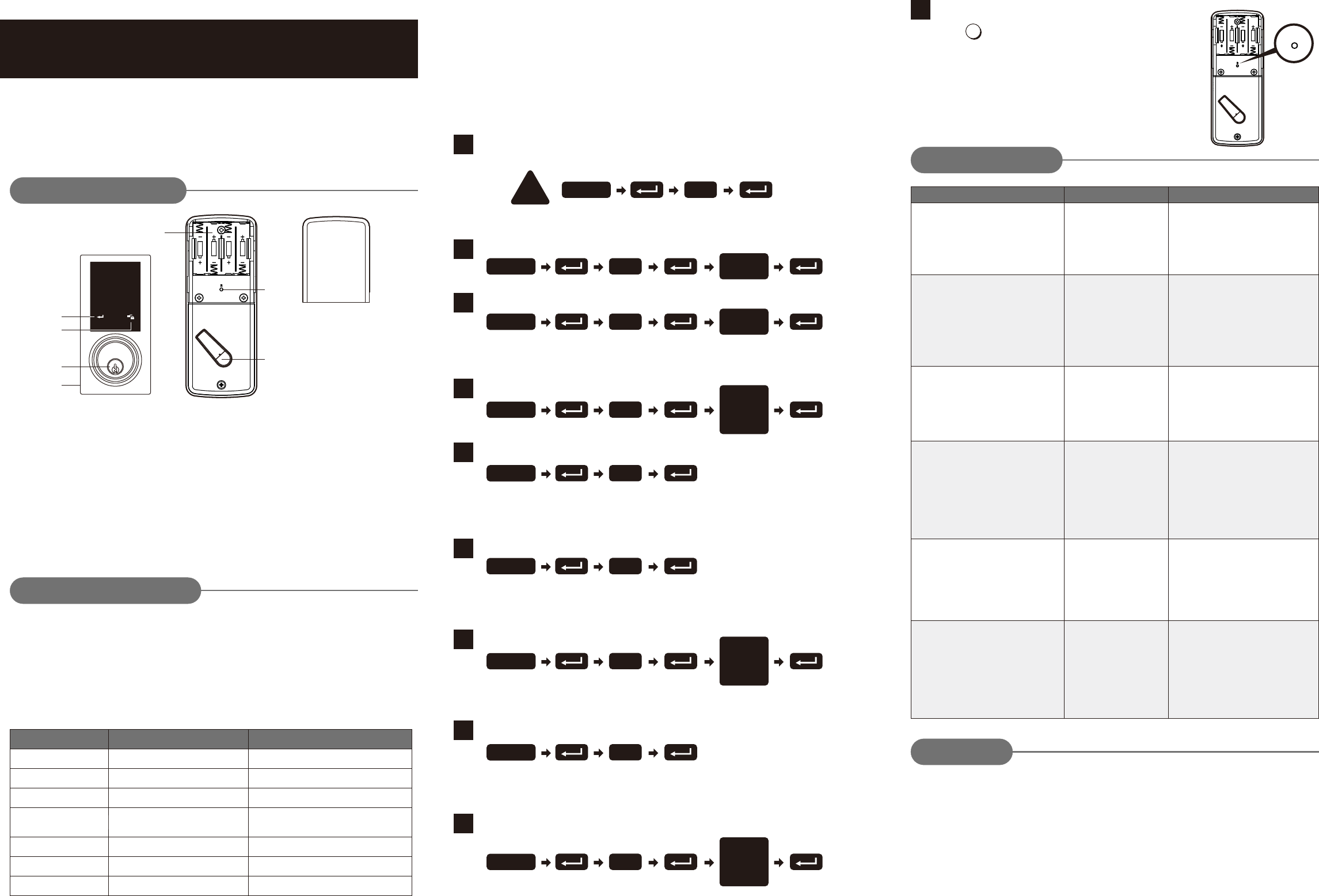
Operation Indicator Sounds and Lights
Sounds Lights Meaning
Successful Operation
Successful Programming
Operation Error
Low Battery Power
Default Setting Restored
In Programming Mode
1 Beep
2 Long Beeps
3 Beeps
5 Beeps
10 Rapid Beeps
Restore Default Settings
Press R
Note: Press the button for more than 5 seconds; the
programming is reset back to the original factory
codes once you hear 3 long beeps.
After restoring default settings, you must run the
door handing identifying process (#1) again before
programming any other functions.
R
Reset
button
Do not use any chemical liquid or lubricating oil with additives
to clean the lock body.
It will damage the surface or even mainboard.
The manufacturer warrants the product to be free from defects in material and workmanship for a period of 12
months from the original date of purchase. If you discover a defect in the product covered by this warranty, we will
repair or replace the item at our option using new or refurbished components.
EXCLUSIONS
This warranty covers defects in manufacturing discovered while using the products as recommended by the
manufacturer rather than occurred by the act of God, and damages caused by misuse, abuse, and unauthorized
modification.
LIMITED LIABILITY
The manufacturer will not be held liable for incidental or consequential losses or damages from any act of God.
Operational Interface
Battery Lid
Slide the lid to change the batteries.
Battery Holder
Four AA (1.5 V) alkaline batteries.
R Button (Reset)
Restore default settings.
Turn-piece
To lock/unlock the lockset from inside.
Programming Button
Lock Buttons
Cylinder
Washer
Prevents water from permeating into lockset.
Programming button is for setting function.
.
To lock/unlock the lockset from outside.
Lock Button is for lock and unlock function
by key
Operating Instructions
10
Trouble shooting
After installing the lockset and batteries,
the door can’t be locked and three short
beeps are emitted when you press the
lock button.
The door-handing
identification process isn’t
yet complete.
Refer to step1.
When you are in the door-handing
identifying process, you get the red light
flashing three times, and three short
beeps.
Wrong door-handing or
change of the door-handing
in the memory.
Press the R button to restore the system
to factory default setting and re-execute
door-handing identifying process
(step 1)Refer to
PROBLEM POSSIBLE CAUSE CORRECTIVE ACTION
You’ve installed the lockset and batteries,
but you still get no response when you
press any button.
Check to see if the battery polarities
have been reversed or if the battery is
dead.
If so, re-install or change the battery.
If not, please check to see if the cable is
properly connected.
Low battery. Replace with new alkaline batteries.
Although you succeeded in the first
execution of the door-handing identifying
process, the latch still doesn’t work.
(i.e. You can feel the motor attempting to
run.)
The door can be locked normally, but
when you try to unlock it, you hear three
short beeps and the lock won't unlock
when you enter the user code and press
the lock button.
Warranty
Delete an Existing User Code
Delete All User Codes at Once
Default programming code (PC): 0000
Default user code (UC): 1234
Your new programming code (PC) ____________
Your new user code (UC) ___________________
The same programming code and user code cannot be accepted.
The lock will cease operation if unauthorized codes are entered
over 5 times.
The system will unfreeze after 45 seconds.
Door Handing Identification Process
The lock needs to learn if your door is a right- or left-handed.handed
Toggle Auto-Lock On/Off
Set Auto-Lock Time Delay
Create a One-Time User Code 4–10 Digits Long
1
4
5
6
7
8
9
Add New User Code
Change Programming Code
2
3
Electronic BLE Touch Deadbolt
Keep the door open while programming to avoid being locked out accidentally.
The lock contains one factory-preset user code but can be programmed to store
up to a total of thirty additional unique user codes.
Codes can be added and deleted at any time. For first-time programming, use
factory default programming code. It’s recommended to change the default
programming code and default user code right after you install the lock.
Every programming step should be done within 6 seconds.
Code Input Error;
System Shuts Down
3 Long Beeps
Lock button flashes slowly
Note:
4–10 digits in length.
Up to 30 sets of user codes can be saved. User codes should be
Note:
user codes are deleted.
The lock can only be operated by key during that time.
Auto-locking and keypad locking functions will be invalid when
DO THIS FIRST
!0
Enter PC
4
Enter PC Enter
New PC
1
Enter PC Enter
New UC
2
Enter PC
Enter
the UC you
want to
delete
3
Enter PC
Note:
user codes are disabled. The lock can only be operated by key
during the time. Repeat the steps to enable the user codes again.
Auto-locking and keypad locking functions will be invalid when
Note: The one-time user code will automatically cancel after it is used
one time.
Note:
following instructions #7.
Repeat the steps in #6 to cancel the auto-locking function.
The preset delay-time is 30 seconds, you can change the time by
Note: 10–99 seconds delay-time available.
5
Enter PC
6
Enter PC
Enter
Seconds
(10~99)
7
Enter PC
8
Enter PC
Enter
One Time
Code
Batteries were installed
incorrectly and cable
connect incorrectly.
The functioning of the
micro-switch is abnormal.
Call our customer service department.
Brand: EZSET
Model: PL2-BT
(1) The depth of the latch
bolt hole is insufficient.
(2) The latch bolt is not
aimed at the opening
of the strike.
While the door is locked, you hear the
latch bolt coming out when you press the
to lock the door; however, three short
beeps are emitted.
Conversely, while the door is open, no
beeps are emitted when locking the
latch bolt.
(1) Dig the latch bolt hole for the strike
(2) Adjust the strike to the appropriate
position.
deeper.
The minimum depth is 1" (2.5 cm).
Enable/Disable All User Codes
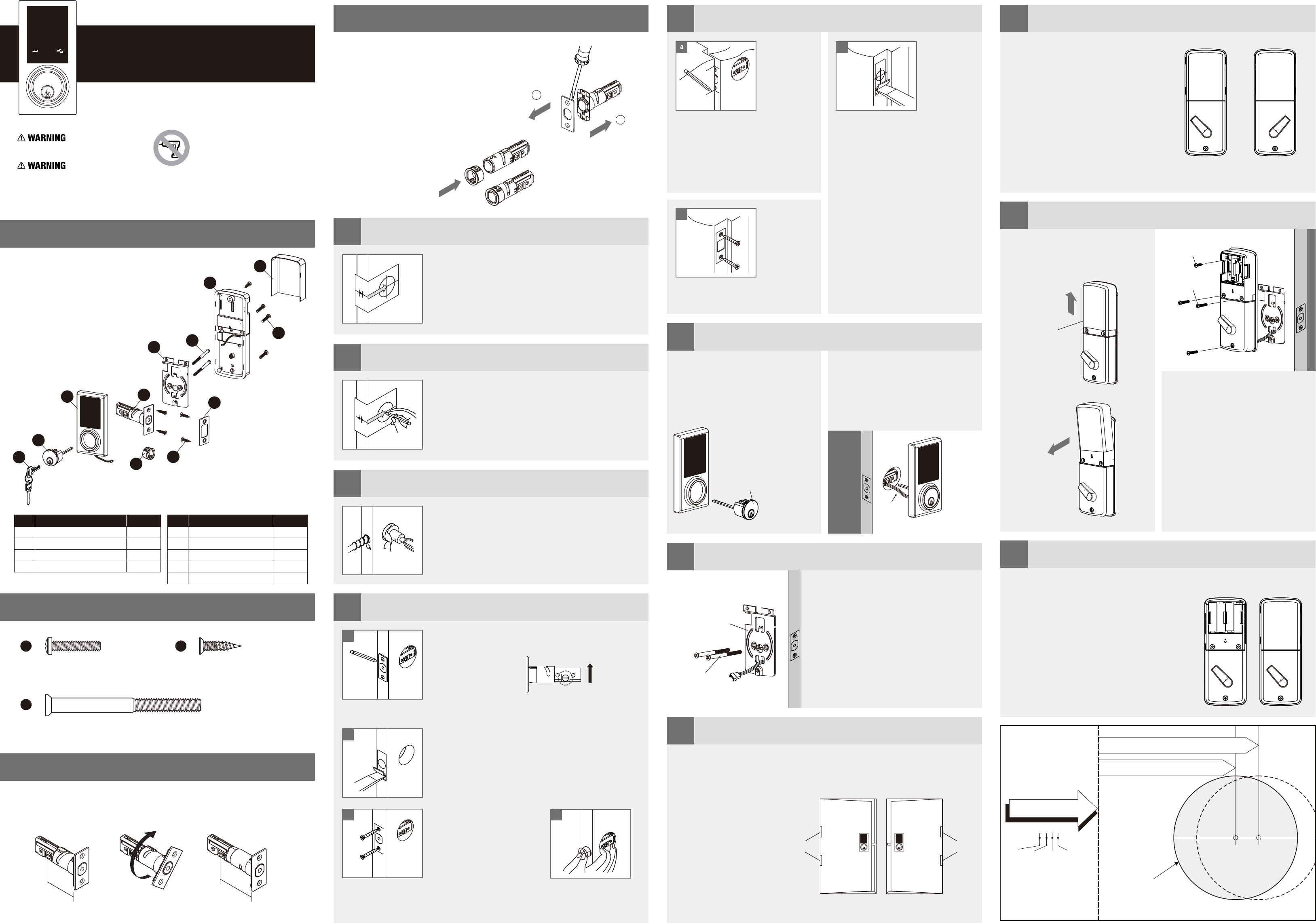
Insert the latch and ensure it is parallel to the door face.
Mark the outline of the faceplate, then take out the latch.
faceplate to be aligned with the door edge.
Note: It is not necessary to chisel the door edge for the
faceplate installation if you use the drive-in latch.
Chisel 5/32" (4 mm) deep along the outline to allow the
Install Latch
You need to stay this
way up when inserting
the latch.
Insert the latch into the door.
(Make sure the cross is on the
bottom of the latch.)
Use 2 wood screws to secure
latch.
Please do not fully tighten the
screws until lock is completely
installed. Install Drive-in Latch
Drive the latch into the
hole on edge of door.
a
b
cd
4
Mark the Door with Template
Select the height and backset as desired on the
door face; use the TEMPLATE as an indication to
mark the centre of the circle on the door face and
the centre of the door edge.
2
5 9
10
11
6
7
8
Install Strike
Machine Screws Qty. 3 Wood Screws Qty. 5
Deadbolt Chassis Screws Qty. 2
J K
L
Adjust Thumb Turn Piece
Install Receiver Module
Insert Batteries
Install Keypad Assembly
Install Inside Mounting Plate
Identify Door Handing
To identify the centre of strike: close
the door to lay the latchbolt against
the door frame.
Mark the centre line on the doorframe
exactly opposite the latch hole in the
door edge.
Install cylinder into the deadbolt
keypad assembly with tailpiece in
horizontal position inserted through
hub of the latch.
the mounting plate.
Fix the mounting plate with screws.
If outside lock assembly is lopsided,
please loosen the screws to adjust its
position and tighten the screws again.
Pass the IC wire through the wire hole of
Face the door from the outside.
The door is left-handed if the hinges are on the left side of the door,
whereas the door is right-handed if the hinges are on the right side of the door.
the interior side of the door, and
insert the tailpiece through the
cross-shaped crank of the latch
Pass the IC wire under the latch to
.
Install the strike plate into your door
frame and tighten with wood screws.
c
Mounting Plate
Screws
Do not use an electric screwdriver during installation.
This Manufacturer advises that no lock can provide complete security by itself.
This lock may be defeated by forcible or technical means, or evaded by entry elsewhere on the property.
No lock can substitute for caution, awareness of your environment, and common sense.
Builder's hardware is available in multiple performance grades to suit the application.
In order to enhance security and reduce risk, you should consult a qualified locksmith or other security professional.
Backset is a distance from door edge to centr of
hole on door face.
Adjustable latch fits both backset of 2-3/8" (60 mm)
and 2-3/4" (70 mm).
e
Backset Determination
1
Drill Holes
Using the marks as a guide to drill a hole
Ø2-1/8" (54 mm) through the door face for the lockset,
then a hole of Ø1" (25.4 mm) for latch.
3
PACKAGE CONTENTS
HARDWARE SCREWS CONTENTS
Electronic BLE Touch Deadbolt
Installation Guide
b
from door stop and vertically mark
centre line of strike.
Drill 1" (25.4 mm) hole, 1" (25.4 mm)
deep at intersection of horizontal and
vertical line of strike.
Chisel 5/64" (2 mm) deep along the
strike outline to allow the strike to be
aligned with the doorframe.
Measure one half of door thickness
Rotate the thumb turn piece to the LEFT
at 45 degrees for right-handed doors.
Rotate the thumb turn piece to the RIGHT
at 45 degrees for left-handed doors.
Remove the battery cover
(push it up first then pull it out).
a
Screws
Wood Screw
Connect the IC wire into the back of
the receiver module.
Ensure that the deadbolt tailpiece is
engaged with turn piece, then attach
receiver module to the door with
screw.
Use the optional wood screw to
secure the receiver module to wood
doors only.
Insert 4 (AA) 1.5 V alkaline batteries and slide the battery cover back onto the
receiver module.
Remarks:
(1) Alkaline batteries are recommended in order
to stabilize the power supply.
If you don't use alkaline, battery performance
will be reduced greatly.
(2) All settings will be retained in the memory
even if the batteries are completed dead.
TEMPLATE
45mm 40mm 35mm
1-3/4" 1-9/16" 1-3/8"
Fit here on door edge
FOR BACKSET 70 mm)2-3/4" (
FOR BACKSET 60 mm)2-3/8" (
51mm
2"
Mark Ø1" (25.4 mm) hole at
centre of door edge.
Ø ( )2-1/8" 54 mm
For right-handed
door
For left-handed
door
Cylinder
Description Quantity
Part
A
B
C
D
Key
Cylinder
Deadbolt Touchpad Assembly
Deadbolt Latch
2
1
1
1
E
F
Strike Plate
Mounting Plate
1
1
Part Description Quantity
G
H
I
Receiver Assembly
Battery Cover
Drive-in Sleeve
1
1
1
123
456
789
0
Brand: EZSET
Model: PL2-BT
A
B
CDE
F
G
H
I
L
K
J
Determine if the latch needs to be adjusted to the 2-3/4" (70 mm) backset.
To adjust, rotate the latch until it stops.
Reverse the direction to return to the 2-3/8" (60 mm) backset.
LATCH ADJUSTMENT
180°
2 3/4" (70 mm)2 3/8" (60 mm)
70 mm
60 mm
CHANGE LATCH FACE
Drive-in Latch
b
a
Determine which latch mounting method will be used
and make necessary adjustments.
No adjustment required for square latch face plate.
a. Use a flat screwdriver to separate the face plate.
b. Snap selected latch face onto back plate.
Drive-in Installation
Remove original latch faceplate.
Align the as illustrated
and snap into the latch case.
drive-in sleeve
IC wire
Left-handed Right-handed
Hinge Hinge
Battery Cover
a
Note : The thumb turn piece is opposite
to the latching side.