Top Victory Electronics LM561S 15" LCD Monitor User Manual LM510 969 4A
Top Victory Electronics (Taiwan) Co Ltd 15" LCD Monitor LM510 969 4A
Contents
- 1. LM500 users manual
- 2. LM510 users manual
LM510 users manual

Plug & Play Drivers for the AOC Spectrum Series Monitors are available
at AOC’s Web Site: www.AOCmonitor.com
LM-510
USER MANUAL
TABLE OF CONTENTS
FOR YOUR SAFETY -------------------------------------------------- 1
SAFETY PRECAUTIONS -------------------------------------- 2
SPECIAL NOTES ON LCD MONITORS ------------------- 3
BEFORE YOU OPERATE THE MONITOR --------------------- 3
FEATURES -------------------------------------------------------- 3
PACKING LIST --------------------------------------------------- 3
INSTALLATION INSTRUCTIONS --------------------------- 4
CONTROLS AND CONNECTORS -------------------------- 5
ADJUSTING THE VIEWING ANGLE ------------------------ 6
OPERATING INSTRUCTIONS ------------------------------------- 7
GENERAL INSTRUCTIONS ---------------------------------- 7
HOW TO ADJUST A SETTING ------------------------------- 9
ADJUSTING THE PICTURE -------------------------------- 9-10
HOW TO OPTIMIZE THE DOS-MODE----------------------- 10
PLUG AND PLAY -------------------------------------------------- 11
TECHNICAL SUPPORT(FAQ) ----------------------------------- 12-13
ERROR MESSAGE & POSSIBLE SOLUTION ----------- 14
HOW TO INSTALL INF & ICM FILE --------------------------- 15
APPENDIX ----------------------------------------------------------------- 16
SPECIFICATIONS --------------------------------------------- 16-17
FACTORY PRESET TIMING TABLE -------------------------- 18
CONNECTOR PIN ASSIGNMENT ----------------------------- 18
LIMITED THREE-YEAR WARRANTY --------------------------- 19-20
Thank you very much for choosing AOC LM-510 LCD Monitor.
We recommend that you take a few minutes to read carefully through this
manual before installing and switching on the monitor. Please keep this
manual in a safe place for your future reference.

1
Before operating the monitor please read this manual thoroughly. This
manual should be retained for future reference.
FCC Class B Radio Frequency Interference Statement
WARNING: (FOR FCC CERTIFIED MODELS)
NOTE: This equipment has been tested and found to comply with the limits
for a Class B digital device, pursuant to Part 15 of the FCC Rules. These
limits are designed to provide reasonable protection against harmful
interference in a residential installation. This equipment generates, uses and
can radiate radio frequency energy, and if not installed and used in
accordance with the instructions, may cause harmful interference to radio
communications. However, there is no guarantee that interference will not
occur in a particular installation. If this equipment does cause harmful
interference to radio or television reception, which can be determined by
turning the equipment off and on, the user is encouraged to try to correct the
interference by one or more of the following measures:
1. Reorient or relocate the receiving antenna.
2. Increase the separation between the equipment and receiver.
3. Connect the equipment into an outlet on a circuit different from that to
which the receiver is connected.
4. Consult the dealer or an experienced radio/TV technician for help.
NOTICE
1. The changes or modifications not expressly approved by the party
responsible for compliance could void the user's authority to operate the
equipment.
2. Shielded interface cables and AC power cord, if any, must be used in
order to comply with the emission limits.
3. The manufacturer is not responsible for any radio or TV interference
caused by unauthorized modification to this equipment. It is the
responsibilities of the user to correct such interference.
As an ENERGY STAR Partner Envision Peripherals, Inc. has determined
that this product meets the ENERGY STAR guidelines for energy efficiency.
WARNING:
To prevent fire or shock hazard, do not expose the monitor to rain or moisture.
Dangerously high voltages are present inside the monitor. Do not open the
cabinet. Refer servicing to qualified personnel only.

2
lDo not use the monitor near water, e.g. near a bathtub, washbowl, kitchen
sink, laundry tub, swimming pool or in a wet basement.
lDo not place the monitor on an unstable cart, stand, or table. If the
monitor falls, it can injure a person and cause serious damage to the
appliance. Use only a cart or stand recommended by the manufacturer or
sold with the monitor. If you mount the monitor on a wall or shelf, use a
mounting kit approved by the manufacturer and follow the kit instructions.
lSlots and openings in the back and bottom of the cabinet are provided for
ventilation. To ensure reliable operation of the monitor and to protect it
from overheating, be sure these openings are not blocked or covered. Do
not place the monitor on a bed, sofa, rug, or similar surface. Do not place
the monitor near or over a radiator or heat register. Do not place the
monitor in a bookcase or cabinet unless proper ventilation is provided.
lThe monitor should be operated only from the type of power source
indicated on the label. If you are not sure of the type of power supplied to
your home, consult your dealer or local power company.
lThe monitor is equipped with a three-pronged grounded plug, a plug with
a third (grounding) pin. This plug will fit only into a grounded power outlet
as a safety feature. If your outlet does not accommodate the three-wire
plug, have an electrician install the correct outlet, or use an adapter to
ground the appliance safely. Do not defeat the safety purpose of the
grounded plug.
lUnplug the unit during a lightning storm or when it will not be used for long
periods of time. This will protect the monitor from damage due to power
surges.
lDo not overload power strips and extension cords. Overloading can result
in fire or electric shock.
lNever push any object into the slot on the monitor cabinet. It could short
circuit parts causing a fire or electric shock. Never spill liquids on the
monitor.
lDo not attempt to service the monitor yourself; opening or removing
covers can expose you to dangerous voltages and other hazards. Please
refer all servicing to qualified service personnel.
lTo ensure satisfactory operation, use the monitor only with UL listed
computers which have appropriate configured receptacles marked
between 100 - 240V AC, Output 12Vdc Min. 3.5A.
lThe wall socket shall be installed near the equipment and shall be easily
accessible.
lFor use only with power adaptor manufacturer by :
Li Shin LSE9901B1250
Delta ADP-50XB, ADP-40TB
Linearity LAD6019AB4
Samsung 80AL15-7-SS(SA) (IBM)
PRECAUTIONS

3
The following symptoms are normal with LCD monitor and do not indicate a
problem.
NOTES
•Due to the nature of thefluorescent light, the screen may flicker during
initial use. Turn off the Power Switch and then turn it on again to make
sure the flicker disappears.
•You may find slightly uneven brightness on the screen depending on the
desktop pattern you use.
•The LCD screen has effective pixels of 99.99% or more. It may include
blemishes of 0.01% or less such as a missing pixel or a pixel lit all of the
time.
•Due to the nature of the LCD screen, an afterimage of the previous screen
may remain after switching the image, when the same image is displayed
for hours. In this case, the screen is recovered slowly by changing the
image or turning off the Power Switch for hours.
•The life of the fluorescent light used in the LCD monitor is approximately
10,000 hours. Contact your dealer or EPI service center for replacement
when the screen is dark, flickering or not lighting up. Never attempt to
replace it by yourself.
BEFORE YOU OPERATE THE MONITOR
FEATURES
•38.1cm(15”) TFT Color LCD Monitor
•Crisp, Clear Display for Windows
•Recommened Resolutions: 1024 X 768 @60Hz
•EPA ENERGY STAR®
•Ergonomic Design (MPRII Approved)
•Space Saving, Compact Case Design
The product package should include the following items:
1. LCD Monitor
2. Owner's Manual
3. Power Cord
4. External Adapter
5. Driver-Disk
FEATURES
CHECKING THE CONTENTS OF THE LM-510 PACKAGE
SPECIAL NOTES ON LCD MONITORS
4
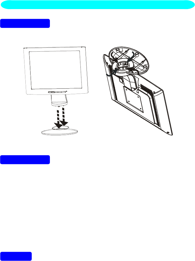
INSTALLATION INSTRUCTIONS
SWIVEL BASE
Install Remove
Figure 1 Installing and Removing the Swivel Base
POWERCORD
Power Source:
1. Make sure the power cord is the correct type that required in your area.
2. This LCD monitor has a universal power supply that allows operation in
either 100/120V AC or 220/240V AC voltage area (No user adjustment is
required.)
3. Connect the power cord into your LCD monitor’s power input socket, and
then plug the other end into a 3-pin AC power outlet. The power cord may
be connected to either a wall power outlet or the power outlet socket on
your PC, depending on the type of power cord supplied with your LCD
monitor.
NOTES
A certified power supply cord has to be used with this equipment. The
relevant national installation and/or equipment regulations shall be
considered. A certified power supply cord not lighter than ordinary polyvinyl
chloride flexible cord according to IEC 60227 (designation H05VV-F 3G
0.75mm
cord be of synthetic rubber according to IEC 60245 (designation H05RR-F 3G
0.75mm
INSTALLATION INSTRUCTIONS
5
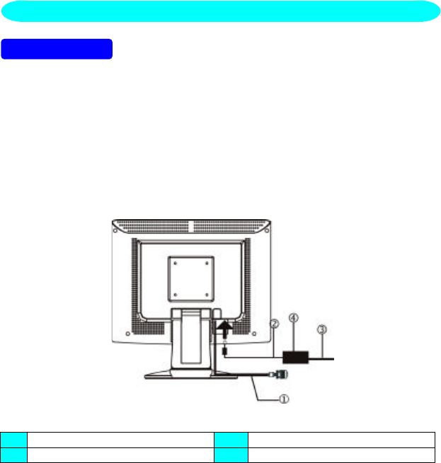
VIDEO CABLE
Connecting the Video Cable: the LCD monitor comes with a built-in video
cable. Plug the signal cable′s 15-pin connector into the computer's video port
and tighten the two screws on the cable connector.
Connecting the Power Cord: Plug the power cord into the LCD monitor's AC
power socket. Then plug the power cord into a grounded AC outlet or UL-
approved power strip or the power output socket on your PC.
Caution: If the AC outlet is not grounded (with three holes), install the proper
grounding adapter (not supplied).
Figure 2 Connecting Cables
1. Signal Cable 3. AC Power Cord
2. DC-Jack Power Cable 4. External Adapter
CONTROLS AND CONNECTORS
6
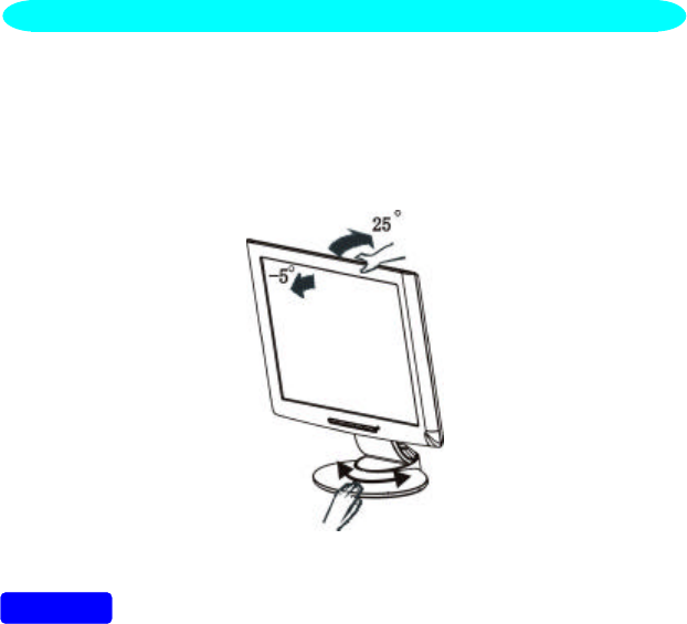
INSTALLATION INSTRUCTIONS
•For optimal viewing it is recommended to look at the full face of the
monitor, then adjust the monitor’s angle to your own preference.
•Hold the stand so you do not topple the monitor when you change the
monitor’s angle.
•You are able to adjust the monitor’s angle from -5° to 25°.
Figure 3
NOTES
•Do not touch the LCD screen when you change the angle. It may cause
damage or break the LCD screen.
•Careful attention is required not to catch your fingers or hands when you
change the angle.
ADJUSTING THE VIEWING ANGLE
7
OPERATING INSTRUCTIONS
Press the power button to turn the monitor on or off. The other control knobs
are located at front panel of the monitor (See Figure 4). By changing these
settings, the picture can be adjusted to your personal preferences.
•The power cord should be connected.
•Connect the video cable from the monitor to the video card.
•Press the power button to turn on the monitor position. The power
indicator will light up.
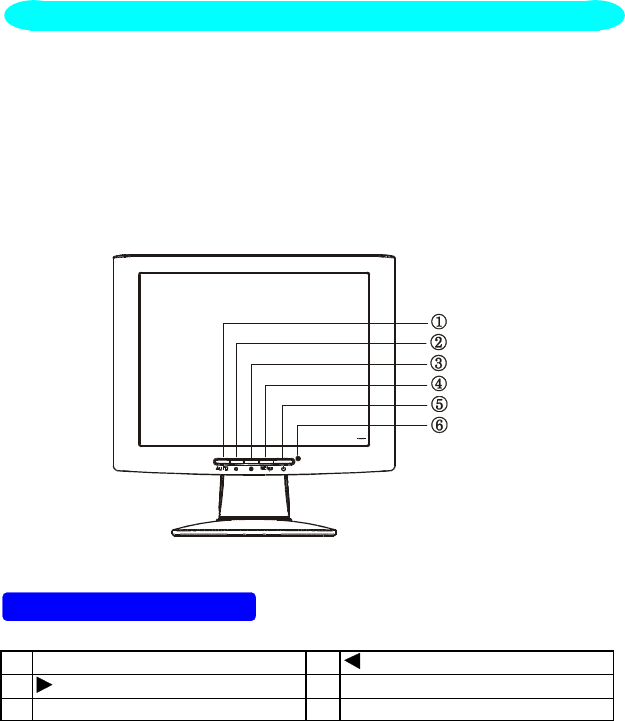
Figure 4 External Control Knob
EXTERNAL CONTROLS
1. Auto Config / Exit 2. / Brightness
3. / Contrast 4. MENU / ENTER
5. Power Button 6. LED
GENERAL INSTRUCTIONS

8
FRONT PANEL CONTROL
•Power:
Press this knob to switch ON/OFF of monitor’s power.
•MENU/Exit :
Active OSD menu or function adjust confirm or Exit OSD menu when in
Brightness/Contrast OSD status.
•Contrast / :
Adjust contrast or function adjust.
•Brightness / :
Adjust brightness or function adjust.
•Auto Config Key:
The Auto Adjust Key is used to automatically set the H POs, V Pos, Clock
and Focus.
•Power Indicator:
Green —Power On mode.
Orange —Off mode.
NOTES
•Do not install the monitor in a location near heat sources such as
radiators or air ducts, or in a place subject to direct sunlight, or excessive
dust or mechanical vibration or shock.
•Save the original shipping carton and packing materials, as they will come
in handy if you ever have to ship your monitor.
•For maximum protection, repackage your monitor as it was originally
packed at the factory.
•To keep the monitor looking new, periodically clean it with a soft cloth.
Stubborn stains may be removed with a cloth lightly dampened with a mild
detergent solution. Never use strong solvents such as thinner, benzene,
or abrasive cleaners, since these will damage the cabinet. As a safety
precaution, always unplug the monitor before cleaning it.
9
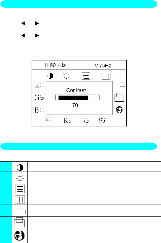
1. Press the MENU-Key to make the OSD window appear. See figure 5.
2. Press or to select the desired function. See figure 5.
3. Press the MENU-Key to select the function that you want to adjust.
4. Press or to change the settings of the current function.
5. When the OSD window is active, it shows the input signal timing. The "H"
stands for the horizontal frequency and "V" for the vertical frequency.
6. To exit and save, select the exit functions, or leave the monitor alone for
10 seconds. If you want to adjust any other function, repeat steps 2-4.
Figure 5 The OSD Message
The description for function control LEDS
1. Contrast Adjust the picture contrast.
2. Brightness Adjust the picture brightness.
3. Focus Adjust picture Focus.
4. Clock Adjust picture Clock.
5. H- Position Adjust the horizontal position of the picture.
6. V- Position Adjust the vertical position of the picture.
7. Language Multi-Language selection
ADJUSTING THE PICTURE
HOW TO ADJUST A SETTING
10
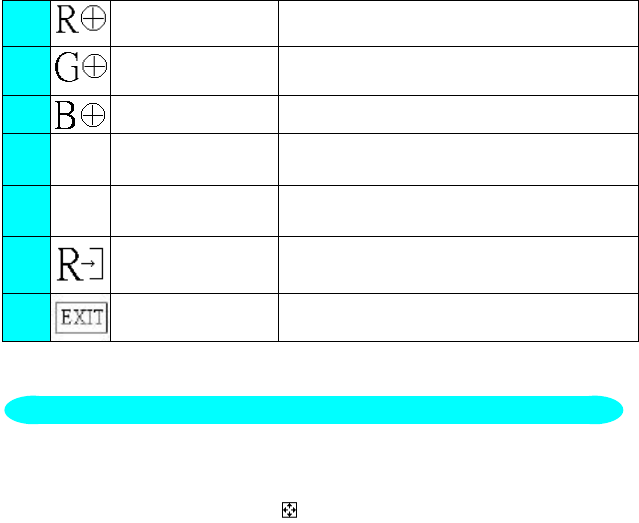
8. Red Adjusts Red intensity.
9. Green Adjusts Green intensity.
10. Blue Adjusts Blue intensity.
11. 73 (7300K) Color The color temperature for 7300°K is
x=0.301, y=0.317.
12. 93 (9300K) Color The color temperature for 9300°K is
x=0.281, y=0.311.
13. Reset Clear each old status of auto-configuration
And re-do auto-configuration.
14. Exit Save user adjustment and OSD disappear.
1. Use the full-screen pattern which is attached in your driver-disk to start the
adjustment ( press twice at Dos1.exe , and expand the picture to full
screen with pressing the icon on the top of window, but there is
nothing to press if the picture is already full screen )
If you don’t have monitor driver disk, you can try the following way to get
the full screen pattern at MS-DOS mode , type in C:\> EDIT [press enter]
You will be in the Dos-Editor screen
2. Press “AUTO” button( at front bezel) during 2 seconds , the monitors will
do all the adjustment automatically
3. Press “ESC” to quit the pattern file ,or press ALT-F, and then X to exit
from the Dos-Editor screen
If the DOS-MODE characters still have distortion
example : ●the picture can’t go to full screen
●the background of white pattern has vertical stripe noise
●the character twisted
that means your monitor parameter was in wrong resolution, please check if
your VGA-CARD supports 720x400 @ 70 Hz
in general, most of the Dos mode was set by VGA-CARD in resolution
720x400@70Hz, but minor was set in 640x400 @ 70Hz ( our monitor only
supports 720x400@70Hz)
HOW TO OPTIMIZE THE DOS-MODE

11
Plug & Play DDC1/2B Feature
This monitor is equipped with VESA DDC1/2B capabilities according to the
VESA DDC STANDARD. It allows the monitor to inform the host system of its
identity and, depending on the level of DDC used, communicate additional
information about its display capabilities. The communication channel is
defined in two levels, DDC1 and DDC2B.
The DDC1 is a unidirectional data channel from the display to the host that
continuously transmits EDID information. The DDC2B is a bidirectional data
channel based on the I²C protocol. The host can request EDID information
over the DDC2B channel.
THIS MONITOR WILL APPEAR TO BE NON-FUNCTIONAL IF THERE IS
NO VIDEO INPUT SIGNAL. IN ORDER FOR THIS MONITOR TO OPERATE
PROPERLY, THERE MUST BE A VIDEO INPUT SIGNAL.
This monitor meets the Green monitor standards as set by the Video
Electronics Standards Association (VESA) and/or the United States
Environmental Protection Agency (EPA) and The Swedish Confederation
Employees (NUTEK). This feature is designed to conserve electrical energy
by reducing power consumption when there is no video-input signal present.
When there is no video input signal this monitor, following a time-out period,
will automatically switch to an OFF mode. This reduces the monitor's internal
power supply consumption. After the video input signal is restored, full power
is restored and the display is automatically redrawn. The appearance is
similar to a "Screen Saver" feature except the display is completely off. The
display is restored by pressing a key on the keyboard, or clicking the mouse.
USING THE RIGHT POWER CORD :
The accessory power cord for the Northern American region is the wallet plug
with NEMA 5-15 style and is UL listed and CSA labeled. The voltage rating for
the power cord shall be 125 volts AC.
Supplied with units intended for connection to power outlet of personal
computer: Please use a cord set consisting of a minimum No. 18 AWG, type
SJT or SVT three conductors flexible cord. One end terminates with a
grounding type attachment plug, rated 10A, 250V, CEE-22 male configuration.
The other end terminates with a molded-on type connector body, rated 10A,
250V, having standard CEE-22 female configuration.
Please note that power supply cord needs to use VDE 0602, 0625, 0821
approval power cord in European counties.
PLUG AND PLAY

12
TECHNICAL SUPPORT (FAQ)
Problem & Question Possible Solution
Power LED is not on *Check if the Power Switch is in the ON
position
*Power Cord should be connected
No Plug & Play *Check if the PC system is Plug & Play
compatible
*Check if the Video Card is Plug & Play
compatible
*Check if the D-15 plug pin of Video
Cable is bent
*Make sure the AOC Monitor Drivers are
installed
(AOC Monitor Drivers are available at:
www.AOCmonitor.com)
Picture is fuzzy *Adjust the Contrast and Brightness
Controls.
Picture bounces or a wave
pattern is present in the picture *Move electrical devices that may cause
electrical interference.
The power LED is ON (orange)
but there’s no video or no
picture.
*Computer Power Switch should be in
the ON position.
*Computer Video Card should be snugly
seated in its slot
*Make sure monitor’s video cable is
properly connected to the computer.
*Inspect monitor’s video cable and make
sure none of the pins are bent.
*Make sure computer is operational by
hitting the CAPS LOCK key on the
keyboard while observing the CAPS
LOCK LED. The LED should either
turn ON or OFF after hitting the CAPS
LOCK key.
Missing one of the primary
colors (RED, GREEN, or
BLUE)
*Inspect the monitor’s video cable and
make sure that none of the pins are
bent.

13
Screen image is not centered or sized
properly. *Adjust pixel frequency (CLOCK) and
FOCUS or press hot-key (AUTO)
Picture has color defects
(white does not look white) *Adjust RGB color or select color
temperature
Poor brightness or contrast *The life time of the back-light is
limited.In 10000 Hours the luminance
of the light has been reduced to half
of its original value. Please send the
monitor to an authorized service
Agent for service.
Horizontal or vertical disturbancies on
the screen *Use win 95/98 shut-down mode
Adjust CLOCK and FOCUS or
perform hot- key (AUTO-key).
CLOCK (pixel frequency) controls the number of pixels scanned by one
horizontal sweep. If the frequency is not correct, the screen shows vertical
stripes and the picture has not correct width.
FOCUS adjust the phase of the pixel clock signal. With a wrong phase
adjustment the picture has horizontal disturbances in light picture.
For FOCUS and CLOCK adjustment use “dot-pattern” or win 95/98 shut-down
mode pattern .
14
CABLE NOT CONNECTED :
1. Check that the signal-cable is properly connected , If the connector is
loose, tighten the connector’s screws.
2. Check the signal-cable’s connection pins for damage.
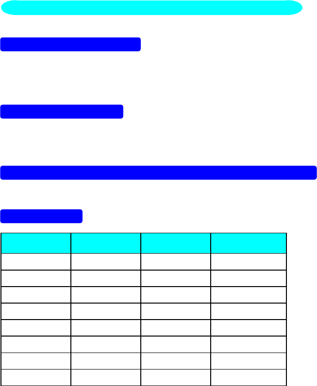
INPUT NOT SUPPORT :
Your computer has been set to unsuitable display mode ,Set the computer to
display mode given in the following table.
UNSUPPORTED MODE TRY DIFFERENT VIDEO CARD SETTING:
Your computer resolution is out of VESA-SPEC
RESOLUTION :
RESOLUTION VERTICAL
FREQUENCY RESOLUTION VERTICAL
FREQUENCY
640 × 480 60Hz 800 × 600 60.3Hz
640 × 350 70Hz 800 × 600 72.2Hz
720 × 400 70Hz 800 × 600 75Hz
640 × 480 72.8Hz 832 × 624 74.5Hz
640 × 480 75Hz 1024 × 768 60Hz
640 × 480 66.67Hz 1024 × 768 70Hz
800 × 600 56.3Hz 1024 × 768 75Hz
1024 × 768 74.92Hz
ERROR MESSAGE & POSSIBLE SOLUTION

15
FOR FIRST TIME INSTALL :
1. Check this LCD MONITOR LM-510 is properly connected to your
computer.
2. Restart the computer , when win98 detects the presence of a Plug and
Play Monitor ,its device driver can be loaded and configured dynamically,
insert LM-510 install disk to DISK A after the Win95/98 setup wizard is
appear. This setup wizard will lead you through the steps for configuring
the system.
(Select “ NEXT “ for next steps and select driver A for LM-510 install file,
if not select driver A ,the configuration system will automatic select the
standard Plug and Play driver)
3. After the installation complete you can find the monitor complete name
by following steps :
Click “START” , select “SETTINGS”, select “CONTROL PANEL “Select
“SYSTEM”, select “DEVICE MANAGEMENT“, select “MONITOR” icon
and click twice ,you can see the Description as follow :
“AOC LCD MONITOR LM-510 “
if this description doesn’t exist, or the “MONITOR” icon no exist too,that
means your installation not success.
Please delete the Description with click the right button of mouse, and
select The “remove or erase” to delete the description, if your steps is
success, the “MONITOR “ icon will disappear.
Please repeat this 2, 3 steps if not success
HOW TO INSTALL INF & ICM FILE
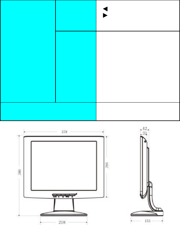
16
APPENDIX
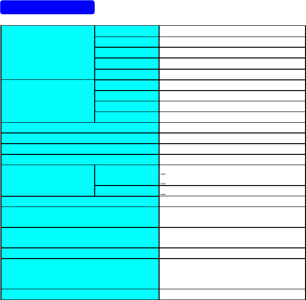
SPECIFICATIONS
Driving system TFT Color LCD
LCD Panel Size 38.1cm(15.0")
Pixel pitch 0.297mm( H )x 0.297mm( V )
Viewable angle 120° (H) 85° (V)
Response time 50 ms
Video R,G,B Analog Interface
Input Separate Sync. H/V TTL
H-Frequency 30kHz – 60kHz
V-Frequency 55-75Hz
Display Colors 16.7 million Colors (for CPTpanel)
Dot Clock 80MHz
Max. Resolution 1024 x 768
Plug & Play VESA DDC1/2BTM
EPA ENERGY STAR®ON Mode <25W ( For 2 CCFL)
<35W ( For 4 CCFL)
OFF Mode <3W
Input Connector D-Sub 15pin
Input Video Signal Analog:0.7Vp-p(standard),
75 OHM, Positive
Maximum Screen Size Horizontal : 12.0”(304.1mm)
Vertical : 9.0”(228.1mm)
Power Source 12Vdc 4A
Environmental
Considerations Operating Temp: 0° to 40°C
Storage Temp.: -20° to 60°C
Operating Humidity : 10% to 90%
Weight (N. W.) 4.7kgs
17
Switch •Auto Adjust Key
• / Brightness
• / Contrast
•Power Switch
•MENU/ Exit
External Controls: Functions •Contrast
•Brightness
•Focus
•Clock
•H-Position
•V-Position
•Language
•7300°K
•9300°K
•RGB Color temperature
•Reset
•Exit
Regulatory
Compliance UL, CSA, FCC, TÜV, CE,
ISO13406-2, MPR II
TCO’99
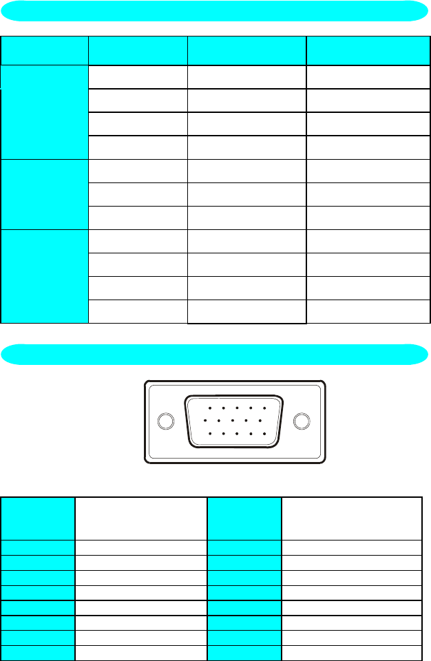
18
STANDARD RESOLUTION HORIZONTAL
FREQUENCY VERTICAL
FREQUENCY
720 × 400 31.47kHz 70Hz
VGA 640 × 480 31.47kHz 60Hz
640 × 480 35.00kHz 66.6Hz
640 × 480 37.50kHz 75Hz
800 × 600 37.879kHz 60Hz
SVGA 800 × 600 46.875kHz 75Hz
832 × 624 49.725kHz 75Hz
1024 × 768 48.363kHz 60Hz
XGA 1024 × 768 56.476kHz 70Hz
1024 × 768 60.02kHz 75Hz
1024 × 768 60.241kHz 74.9Hz
1 5
610
11 15
15 - Pin Color Display Signal Cable
PIN NO. DESCRIPTION PI N NO. DESCRIPTION
1. Red 9. +5V
2. Green 10. Detect Cable
3. Blue 11. Ground
4. Ground 12. DDC-Serial Data
5. Ground 13. H-Sync
6. R-Ground 14. V-Sync
7. G-Ground 15. DDC-Serial Clock
8. B-Ground
FACTORY PRESET TIMING TABLE
CONNECTOR PIN ASSIGNMENT

19
WARRANTY STATEMENT
for AOC Color Monitors
Including those Sold within North America as Specified
Envision Peripherals, Inc. warrants this product to be free from defects in
material and workmanship for a period of three (3) years after the original
date of consumer purchase. During this period, EPI (EPI is the abbreviation
for Envision Peripherals, Inc.) will, at its option, either repair the defective
product with new or rebuilt parts, or replace it with a new or rebuilt product at
no charge except as *stated below. The parts or product that are replaced
become the property of EPI.
In the USA to obtain service under this limited warranty, call EPI for the
name of the Authorized Service Center in your area. Deliver the product
freight pre-paid, along with the dated proof of purchase, to the EPI
Authorized Service Center. If you cannot deliver the product in person:
lPack it in its original shipping container (or equivalent)
lPut the RMA number on the address label
lPut the RMA number on the shipping carton
lInsure it (or assume the risk of loss / damage during shipment)
lPay all shipping charges
EPI is not responsible for damage to inbound product that was not properly
packaged.
EPI will pay the return shipment charges within one of the countries specified
within this warranty statement. EPI is not responsible for any costs associated
with the transportation of product across international borders. This includes
the international borders of the countries within this warranty statement.
In the United States and Canada contact your Dealer or EPI Customer Service,
RMA Department at the toll free number (888) 838-6388.
* This limited warranty does not cover any losses or damages that occur as a
result of:
lShipping or improper installation or maintenance
lMisuse
lNeglect
lAny cause other than ordinary commercial or industrial application
lAdjustment by non-authorized source
lRepair, modification, or installation of options or parts by anyone other
than an EPI Authorized Service Center
20
lImproper environment
lExcessive or inadequate heating or air conditioning or electrical power
failures, surges, or other irregularities
This three-year limited warranty does not cover any of the product's firmware
or hardware that you or any third party have modified or altered; you bear the
sole responsibility and liability for any such modification or alteration.
ALL EXPRESS AND IMPLIED WARRANTIES FOR THIS PRODUCT
(INCLUDING THE WARRANTIES OF MERCHANTABILITY AND
FITNESS FOR A PARTICULAR PURPOSE) ARE LIMITED IN
DURATION TO A PERIOD OF THREE (3) YEARS FOR PARTS AND
LABOR FROM THE ORIGINAL DATE OF CONSUMER PURCHASE.
NO WARRANTIES (EITHER EXPRESSED OR IMPLIED) APPLY
AFTER THIS PERIOD. IN THE UNITED STATES OF AMERICA, SOME
STATES DO NOT ALLOW LIMITATIONS ON HOW LONG AN
IMPLIED WARRANTY LASTS, SO THE ABOVE LIMITATIONS MAY
NOT APPLY TO YOU.
EPI OBLIGATIONS AND YOUR REMEDIES HEREUNDER ARE
SOLELY AND EXCLUSIVELY AS STATED HERE. EPI’S LIABILITY,
WHETHER BASED ON CONTRACT, TORT. WARRANTY, STRICT
LIABILITY, OR OTHER THEORY, SHALL NOT EXCEED THE PRICE
OF THE INDIVIDUAL UNIT WHOSE DEFECT OR DAMAGE IS THE
BASIS OF THE CLAIM. IN NO EVENT SHALL ENVISION
PERIPHERALS, INC. BE LIABLE FOR ANY LOSS OF PROFITS, LOSS
OF USE OR FACILITIES OR EQUIPMENT OR OTHER INDIRECT,
INCIDENTAL, OR CONSEQUENTIAL DAMAGE. IN THE UNITED
STATES OF AMERICA, SOME STATES DO NOT ALLOW THE
EXCLUSION OR LIMITATION OF INCIDENTAL OR
CONSEQUENTIAL DAMAGES. SO THE ABOVE LIMITATION MAY
NOT APPLY TO YOU. ALTHOUGH THIS LIMITED WARRANTY
GIVES YOU SPECIFIC LEGAL RIGHTS. YOU MAY HAVE OTHER
RIGHTS WHICH MAY VARY FROM STATE TO STATE.
In the United States of America, this limited warranty is only valid for
Products purchased in the Continental United States, Alaska, and Hawaii.
Outside the United States of America, this limited warranty is only valid for
Products purchased in Canada.
21
Only for AOC branded monitors sold within the continental United States.
All AOC branded monitors that are purchased after April 1st, 2001 are now covered
by the EASE Program. If your monitor malfunctions at any time during the first year,
AOC will provide a replacement monitor within 72 hours after you are approved for
our program. If your monitor qualifies for the EASE program, AOC will pay for
freight both ways.
Step 1: Phone our TECH Department at 888.662.9888
Step 2: Fill out and return EASE registration forms by mail or fax.
Step 3: We will issue a Return Authorization Number upon verification into the
program.
Step 4: A monitor will be advance shipped to your location.
Step 5: We will issue a UPS Call Tag to pick up the defective unit.
Step 6: Please review the following chart to see your EASE program qualifications
WARRANTY
PERIOD COVERAGE AT
NO CHARGE CUSTOMER
CHARGES
Within the 1
st
year of purchase
Covered by EASE •New AOC monitor
•
Call tag dispatched and return
freight charges via UPS
•None*
Between 1-3 Years •All Parts & Labor
•AOC repaired monitor
•
UPS Return Freight to AOC
*AOC will need to obtain a credit card number if you would like to get a new AOC
monitor advanced shipped to your location, prior to the defective unit arriving at
AOC’s service center. If you do not wish to supply a credit card, AOC will only ship
the new monitor, once the defective unit arrives at the AOC service center.
www.AOCmonitor.com
22
P/N : 41A401-969