Topcon America 090521 GNSS Receiver User Manual Introduction
Topcon America Corporation GNSS Receiver Introduction
Contents
HiPerII Operation Manual 1
HiPerII Chapter 1
Introduction
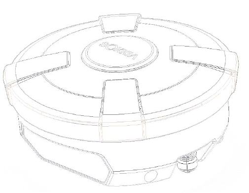
The HiPerII receiver is a multi-frequency, GPS+ receiver built to be the most advanced and
compact receiver for the surveying market. The receiver is a multi-function, multi-purpose
receiver intended for precision markets.
Precision markets means markets for equipment, subsystems, components and software for
surveying, construction, commercial mapping, civil engineering, precision agriculture and
land-based construction and agriculture machine control, photogrammetry mapping,
hydrographic and any use reasonably related to the foregoing.
The HiPerII can receive and processes multiple signal types ( including the latest GPS L1, L2,
C/A, L2C GLONASS L1, L2, C/A signals ) improving the accuracy and reliability of the survey
points and positions, especially under difficult jobsite conditions. The multifrequency and
GPS+ features of the receiver combine to provide a positioning system accurate for any survey.
Several other features, including multipath mitigation, provide under-canopy and low signal
strength reception. The receiver provides the functionality, accuracy, availability, and integrity
needed for fast and easy data collection.
Figure 1-1. HiPerII Receiver
Principles of Operation
Surveying with the right GPS receiver can provide users accurate and precise positioning, a
requirement for any surveying project. This section gives an overview of existing and
proposed Global Navigation Satellite Systems ( GNSS ) and receiver functions so that basic
operating principles can be applied.
HiPerII Chapter 1
HiPerII Chapter 1
GNSS Overview
Currently, the following two global navigation satellite systems ( GNSS ) offer line-of-site radio
navigation and positioning, velocity, and time services on a global, all-weather scale to any user
equipped with a GNSS tracking receiver on or near the Earth's surface:
GPS - the Global Positioning System maintained and operated by the United States
Department of Defense. For information on the status of this system, visit the US Naval
Observatory website ( http://tycho.usno.navy.mil/ ) or the US Coast Guard website
( http://www.navcen.uscg.gov/ ).
GLONASS - the Global Navigation Satellite System maintained and operated by the Russian
Federation Ministry of Defense. For information on the status of this system, visit the
Coordinational Scientific In-formation Center website ( http://www.glonass-ianc.rsa.ru/ ).
Despite numerous technical differences in the implementation of these systems, satellite
positioning systems have three essential components:
Space - GPS and GLONASS satellites orbit approximately 12,000 nautical miles above Earth
and are equipped with a clock and radio. These satellites broadcast ranging signals and
various digital information ( ephemerides, almanacs, time and frequency corrections, and
so forth ).
Control - Ground stations located around the Earth that monitor the satellites and upload
data, including clock corrections and new ephemerides ( satellite positions as a function of
time ), to ensure the satellites transmit data properly.
User - The community and military that use GNSS receivers to calculate positions.
Calculating Absolute Positions
When calculating an absolute position, a stationary or moving receiver determines its
three-dimensional position with respect to the origin of an Earth-Center Earth-Fixed coordinate
system. To calculate this position, the receiver measures the distance ( called pseudo-ranges )
between it and at least four satellites.
The measured pseudo- ranges are corrected for clock differences ( receiver and satellites ) and
signal propagation delays due to atmospheric effects. The positions of the satellites are
computed from the ephemeris data transmitted to the receiver in navigation messages. When
using a single satellite system, the minimum number of satellites needed to compute a position
is four. In a mixed satellite scenario ( GPS, GLONASS ), the receiver must lock onto five or
more satellites to account for the different time scales used in these systems and to obtain an
absolute position.
HiPerII Chapter 1
HiPerII Chapter 1
Calculating Differential Positions
DGPS, or Differential GPS, is a relative positioning technique where the measurements from two
or more remote receivers are combined and processed using sophisticated algorithms to
calculate the receivers' relative coordinates with high accuracy. DGPS accommodates various
implementation techniques that can be classified according to the following criteria:
The type of GNSS measurements used, either code-phase differential measurements or
carrier-phase differential measurements
If real-time or post-mission results required. Real-time applications can be further divided
according to the source of differential data and communication link used.
With DGPS in its most traditional approach, one receiver is placed at a known, surveyed location
and is referred to as the reference receiver or base station. Another receiver is placed at an
unknown location and is referred to as the remote receiver or rover. The reference station
collects the code-phase and carrier-phase measurements from each GNSS satellite in view.
For real-time applications, these measurements and the reference station coordinates are
then built up to the industry standard RTCM - or various proprietary standards established
for transmitting differential data - and broadcast to the remote receiver ( s ) using a data
communication link. The remote receiver applies the transmitted measurement
information to its observed measurements of the same satellites.
For post-mission applications, the simultaneous measurements from reference and rover
stations are normally re-corded to the receiver's internal memory ( not sent over
communication link ). Later, the data are downloaded to computer, combined, and
processed. Using this technique, the spatially correlated errors - such as satellite orbital
errors, ionospheric errors, and tropospheric errors - can be significantly reduced, thus
improving the position solution accuracy.
A number of differential positioning implementations exist, including post-processing surveying,
real-time kinematic surveying, maritime radio beacons, geostationary satellites ( as with the
OmniSTAR service ), and satellite based augmentation systems ( WAAS, EGNOS, MSAS ).
The real-time kinematic (RTK) method is the most precise method of real-time surveying. RTK
requires at least two receivers collecting navigation data and communication data link between
the receivers. One of the receivers is usually at a known location ( Base ) and the other is at
an unknown location ( Rover ). The Base receiver collects carrier phase measurements,
generates RTK corrections, and sends this data to the Rover receiver. The Rover processes this
transmitted data with its own carrier phase observations to compute its relative position with
high accuracy, achieving an RTK accuracy of up to 1.0 cm horizontal and 2.0 cm vertical.
HiPerII Chapter 1
HiPerII Chapter 1
Essential Components for Quality Surveying
Achieving quality position results requires the following elements:
Accuracy - The accuracy of a position primarily depends upon the satellite geometry
( Geometric Dilution of Precision, or GDOP ) and the measurement (ranging) errors.
Differential positioning ( DGPS and RTK ) strongly mitigates atmospheric and orbital
errors, and counteracts Selective Availability ( SA ) signals the US Department of
Defense transmits with GPS signals.
The more satellites in view, the stronger the signal, the lower the DOP number, the
higher positioning accuracy.
Availability - The availability of satellites affects the calculation of valid positions. The
more visible satellites available, the more valid and accurate the position. Natural and
man-made objects can block, interrupt, and distort signals, lowering the number of
available satellites and adversely affecting signal reception.
Integrity - Fault tolerance allows a position to have greater integrity, increasing accuracy.
Several factors combine to provide fault tolerance, including:
Receiver Autonomous Integrity Monitoring ( RAIM ) detects faulty GNSS satellites and
removes them from the position calculation.
Five or more visible satellites for only GPS or only GLONASS; six or more satellites
for mixed scenario
Satellite Based Augmentation Systems ( WAAS, EGNOS, and so on ) creates and
transmit, along with DGPS corrections, data integrity information ( for example,
satellite health warnings ).
Current ephemerides and almanacs.
Conclusion
This overview simply outlines the basics of satellite positioning. For more detailed information,
visit the Sokkia Topcon website.
Receiver Overview
When power is turned on and the receiver self-test completes, the receiver's 72 channels
initialize and begin tracking visible satellites. Each of the receiver's channels can be used to
track any one of the GPS or GALILEO signals. The number of channels available allows the
receiver to track all visible global positioning satellites at any time and location.
HiPerII Chapter 1
HiPerII Chapter 1
An internal GPS+ antenna equipped with a low noise amplifier ( LNA ) and the receiver's radio
frequency ( RF ) device are connected with a co-axial cable. The wide-band signal received is
down-converted, filtered, digitized, and assigned to different channels. The receiver processor
controls the process of signal tracking.
Once the signal is locked in the channel, it is demodulated and necessary signal parameters
( carrier and code phases ) are measured. Also, broadcast navigation data are retrieved from
the navigation frame.
After the receiver locks on to four or more satellites, its absolute position in WGS-84 and the
time offset between the receiver clock and GPS time are computed. This information and the
measurement data can be stored in the optional SD card and downloaded later onto a computer,
then processed using a post-processing software package. When the receiver operates in RTK
mode, raw data measurements can also be recorded into the receiver's internal memory. This
allows the operator to double check real-time results obtained in the field.
Depending on your options, capabilities of the receiver include:
Satellite based augmentation systems ( WAAS, EGNOS, and so forth ).
Adjustable phase locked loop ( PLL ) and delay lock loop ( DLL ) parameters
Dual- or multi-frequency modes, including static, kinematic, real-time kinematic ( RTK ),
and differential GPS ( DGPS ) survey modes ( DGPS modes include static, kinematic, and
RTK )
Auto data logging
Setting different mask angles
Setting different survey parameters
Static or dynamic modes
Getting Acquainted
The HiPerII is a 72-channel GPS receiver, which includes the following:
External, detachable batteries
One data ports
Interface for controlling and viewing data logging
External memory card slot
Internal radio modem
Bluetooth wireless technology module
Optional GSM/GPRS module
Optional CDMA module ( only with the Digital UHF radio modem )
HiPerII Chapter 1
HiPerII Chapter 1
Batteries
The HiPerII receiver comes equipped with one detachable, re-chargeable batteries ( Figure
1-2 ) for powering the receiver.
Figure 1-2. HiPerII Batteries
Please use CDC68 as battery charging cradle.
It takes approximately four hours to completely charge one battery, and eight hours to charge
two batteries. ( In BDC58 use )
HiPerII Receiver
The HiPerII receiver's advanced design reduces the number of cables required for operation,
allowing for more reliable and efficient surveying. The casing allocates space for one
removable, rechargeable batteries, SD and SIM card slots, a Bluetooth wireless technology
module and a radio modem communications board.
The HiPerII comes in one of the following configura-tions:
with an FH915 Plus TX/RX/RP radio modem and a GSM/GPRS module
with a 1W Digital UHF TX/RX radio modem, depending on the country
with a Digital UHF radio modem and a GSM/GPRS module
with a Digital UHF TX/RX radio modem and a CDMA module
Other features include one data ports, a power port, and a MINTER for viewing status and
controlling data input/output.
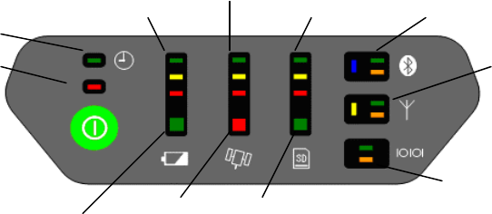
MINTER
The MINTER is the receiver's minimum interface used to dis-play and control data input and
HiPerII Chapter 1
HiPerII Chapter 1
output ( Figure 1-5 ).
Figure 1-5. HiPerII MINTER
Serial Port Status
Radio Status
Battery Status Position Status
Scheduler
A
vailable Power Bar
Satellite Tracking Bar
Memory Capacity Bar
Receiver Health
Wireless Status
File Statius
Available Power Bar indicates battery remaining or voltage.
Green - indicate greater than 50%.
Yellow - indicate greater than 25%.
Red - indicate greater than 10%.
Red blink - indicate less than 10%.
Battery Status LEDs indicates an available battery and the usage condition.
Green - only battery is available.
Red - only external power is available.
Umber - battery and external power are available.
Satellite Tracking Bar indicate number of satellites tracked.
Green - indicate greater than 8 satellites.
Yellow - indicate 6 or 7 satellites.
Red - indicate 4 or 5 satellites.
Red blink - indicate 3, 2, 1 or 0 satellites.
Position Status LEDs indicate current type position computed.
Green - Integer RTK or Fixed RTK.
Umber - DGPS or Float RTK.
Red - Single
Memory Capacity Bar indicate a percentage of available space in the memory.
Green - indicate greater than 50%.
Yellow - indicate greater than 25%.
Red - indicate greater than 10%.
Red blink - indicate greater than 0%.
File Status LEDs indicate status of current file.
Green - file is opened.
Umber blink - writing are done on the file.
( light out ) - file is not opened or there is no memory card in slot.
HiPerII Chapter 1

HiPerII Chapter 1
Wireless Status LEDs indicate status of the internal Blue-tooth module.
Blue - internal Bluetooth connection has been established.
Blue blink - internal Bluetooth connection has not been made, as long as the module has
power.
Blue dark - internal Bluetooth is not being powered.
Green flash - date is transmitted from the Bluetooth port.
Orange flash - date is received from the Bluetooth port.
Radio Status LEDs indicate status of the internal UHF radio and GSM module.
Yellow - internal radio is being powered.
Yellow dark - internal radio is not being powered.
Green flash - date is transmitted from the internal radio port.
Orange flash - date is received from the internal radio port.
Serial Port Status LEDs indicates status of the serial port.
Green flash - data is transmitted from the serial port.
Orange flash - data is received from the serial port.
The power button turns the receiver on, off and receiver setting.
The power button is used to turn the unit on or off, format or erase the internal memory, or
perform a factory reset. The number of seconds that you press the power button de-ter-mines
how the receiver will behave. At each time interval, the receiver issues voice messages or
sounds to guide you through the process.
Action Number of
seconds Description
Tuen on 1
Press the button for 1 second and release to turn on the receiver.
The battery life gauge indicates the progress of the startup
sequence.
After startup (approximately 20 seconds), the battery life gauge
indicators will turn off for a short period, and you will hear the
"Receiver Ready" message or sound that indicates that the
system is operational.
Note:
It is normal for the receiver health indicator LEDs to illuminate
during startup.
Tuen off 3 Press the button for 3 seconds and/or until you hear the "Power
Off" message or sound, and the top three battery life gauge
LEDs illuminate.
HiPerII Chapter 1

HiPerII Chapter 1
Factory
reset 10
With the receiver on, press the button for 1 0 seconds until you
hear the "Factory Reset" message or sound and the top three
LEDs on the battery life, satellite tracking, and memory gauges
illuminate.
Release the button to reset all stored parameters on the receiver
to their default values.
Note:
This action is irreversible.
Erase
memory 20
With the receiver on, press the button for 20 seconds until you
hear the "Delete Files" message or sound and the top three LEDs
on the memory gauge illuminate.
Release the button to delete all the files from the memory.
Note:
This action is irreversible.
If you are unsure about whether you want to delete all the files,
hold the button longer than 25 seconds, so that the receiver
simply returns to normal operation.
To delete individual files from the memory, use a data collector
or SOKKIA TOPCON software on your PC.
Disregard 25
When you hold the button longer than 25 seconds and you hear
the "Continue Operation" message or sound, no action will be
taken, and the receiver will return to normal operation.
The receiver will not turn off, the data files will not be erased,
and the settings will not revert to factory settings.
Data and Power Ports
The HiPerII has the following three ports (Figure 1-6):
Serial - rimmed in blue; used for communication between the receiver and an external
device. The body of the connector on the corresponding cable is blue.
Power - rimmed in red; used to connect the receiver to an external power source. The
body of the connector on the corresponding cable is red.
Figure 1-6. HiPer II Ports
HiPerII Chapter 1
HiPerII Chapter 1
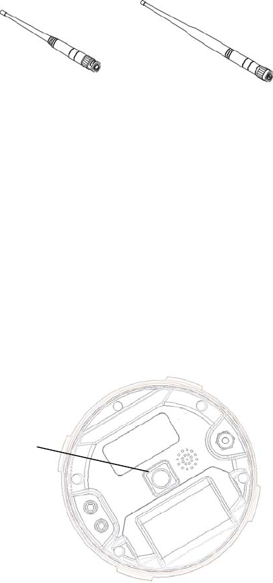
External Radio Antenna Connector
The UHF and SS antennas connect to the external antenna connector under the HiPerII housing
( Figure 1-7 ). Both modem antenna types include support for a GSM modem.
The modem antenna depends on the type of modem in-stalled in the receiver:
UHF: Uses a BNC RF connection and comes in three versions: 410-440MHz ( p/n
30-070003-01 ) and 440-470MHz ( p/n 30-050503-01 ).
Spread Spectrum: Uses a reverse polarity TNC RF connection and comes in one version:
( p/n 30-030012-01 ).
Figure 1-7. Modem Antennas
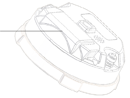
Connector
The bottom connector ( Figure 1-8 ) connects the receiver to either a standard 5/8''thread
pole/adapter or the quick disconnect ( see "The quick disconnect adapter" on page 1-22 for
details ).
Bottom Connector
for Standard Setups
Figure 1-8. HiPerII Quick Connector
HiPerII Chapter 1
HiPerII Chapter 1
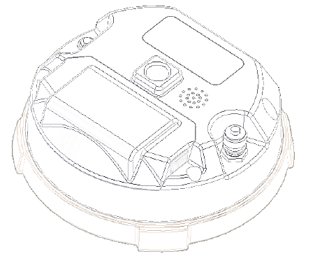
SD/MMC and SIM Card Slots
The SD and SIM card slots reside under the batteries near the base of the dome.
The SD card slot is located to the left of the MINTER inside the battery pocket ( Figure 1-9 )
and connects an optional SD card to the receiver board to provide memory. Once installed, the
SD card usually remains inside the receiver. The data that resides on the SD card can be
accessed via the serial port, or Bluetooth wireless technology. A secure digital card can be
purchased at a local computer supply store.
The SIM card slot is located to the inside the battery pocket and allows a standard SIM card
to be installed in the receiver. Once installed, the SIM card provides a unique identification for
the receiver's GSM module and enables the receiver's GSM functionality based on the
subscribed ser-vices ( the receiver board accesses the GSM module which accesses the SIM
card ). The SIM card usually remains inside the receiver. The GSM module with the SIM card
installed can be accessed via Modem-TPS for configuration purposes. A SIM card can be
purchased from a local cellular provider.
Card Slot
SD and SIM
Figure 1-9. HiPerII Card Slot Example
Cables
The HiPerII package includes standard communication cables for configuring the receiver.
Table 1-3 lists the cables included in the HiPerII package.
Table 1 -3. HiPerII Package Cables
HiPerII Chapter 1
HiPerII Chapter 1
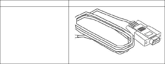
Cable Description Cable Illustration
Serial Cable
Connects the receiver to an
external device ( controller
or computer data transfer
and receiver configuration.
Body of connector back.
p/n xx-xxxxxx-xx
Other Accessories
Battery ( BDC58 ) Li-ion Battery [ 4300mAh,7.2V DC ].
Power system - without Power Cable ( CDC68 ) Battery BDC58 [ about 150min ] ×
2、AC100V [ without AC power cable、CDC68-11 include ]
Power Cable ( EDC113/A/B/C/D/E ) CDC68 to AC consent. It is chosen by every
country.
Quick release ( 086-0-0001 )
Measuring Tape ( 405-0-0013 ) 3.7m HI ( Calibrated )
SD Card FAT16、2GB industrial
CD-ROM include Manual PDF and Config Tool
Carrying Case
For more details on the accessories and package options available for the HiPerII, contact the
local Sokkia Topcon dealer.
Optional Accessories
Sokkia Topcon offers a wide variety of accessories especially designed to extend job reliability
and efficiency. For more details on the optional accessories available for HiPerII, contact the
HiPerII Chapter 1
HiPerII Chapter 1
local Sokkia Topcon dealer.
Interface Cable ( ***** ) For SHC250/SHC2500, Cross connection, D-sub 9pin
Interface Cable ( ***** ) For Computer, Cross connection, D-sub9pin
Tribrach and Tribrach adapter ( WOA )
Tribrach ( WA100A ) w/Optical Plummet
Tribrach adapter (555501 )
Tribrach adapter, Rotating Center ( 501-0-0011 )
Tribrach adapter ( 51861 ) Model S2
Tripod ( PWF1 )
Tripod ( 30-050505-01 ) 2m Fixed Height Tripod
AC Adaptor ( EDC117 )
Interface Cable ( BDC118 )
External Battery Box ( ***** ) Output DC5V, 7.2V, 12V
Power Cable ( ***** )
Bibod ( GP-SP) RTK-GPS, Steel
RTK-GPS Pole ( GP-SP1 ) RTK-GPS, 2m, connection, steel
Slide Pole ( AP61 ) 2m, Caing Case
2M Pole ( 22-050908-01 ) 2m pole Fixed Hieght for HiPerII
Pole Stand ( AP71) with plastic case
Range Pole Level ( AP61L2 ) with reflective mirror, bubble tube detection range 10'
Controller Pole Cramp ( 700264901 ) SECO Co., Product
Controller ( SHC250 ) with Battery, Power System, Cable
Controller ( SHC2500 )
Option Authorization File (OAF)
Sokkia Topcon issues an Option Authorization File ( OAF ) to enable the specific options that
customers purchase. An Option Authorization File allows customers to customize and
configure the receiver according to particular needs, thus only purchasing those options
needed.
Typically, all receivers ship with a temporary OAF that allows it to be used for a predetermined
period of time. When the receiver is purchased, a new OAF permanently activates purchased
options. Receiver options remain intact when clearing the NVRAM or resetting the receiver.
The OAF enables the following kinds of functions. For a complete list of available options and
details, visit the Sokkia Topcon website or consult a Sokkia Topcon dealer.
Type of signal ( standard L1; optional L2, L5 GPS, GLONASS )
HiPerII Chapter 1
HiPerII Chapter 1
Update rate standard 1Hz ( optional 5, 10, or 20Hz )
RTK at 1Hz, 5Hz, 10Hz, and 20Hz
RTCM/CMRInput/Output
Advanced multipath reduction
Wide Area Augmentation System ( WAAS )
Receiver Autonomous Integrity Monitoring ( RAIM )
HiPerII Chapter 1