Topcon America 100926 DIG UHF-II Radio Module User Manual DUHFII ig
Topcon America Corporation DIG UHF-II Radio Module DUHFII ig
UserManual.wiki
>
Topcon America
>
100926 User Manual
>
User's Manual
Contents
1.
User's Manual
2.
Users Manual
3.
COMPREHENSIVE INSTALLATION INSTRUCTIONS
User's Manual
Users Manual
Navigation menu
Upload a User Manual
Namespaces
Wiki Guide
HTML
PDF
Info
Views
User Manual
Discussion / Help
Navigation


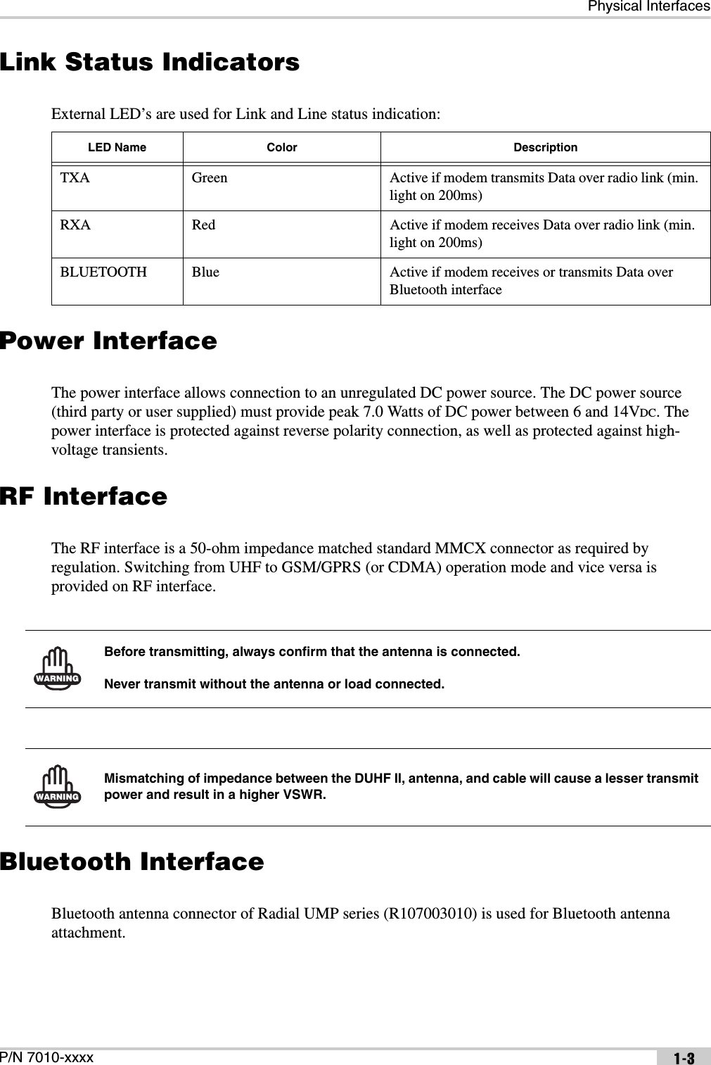


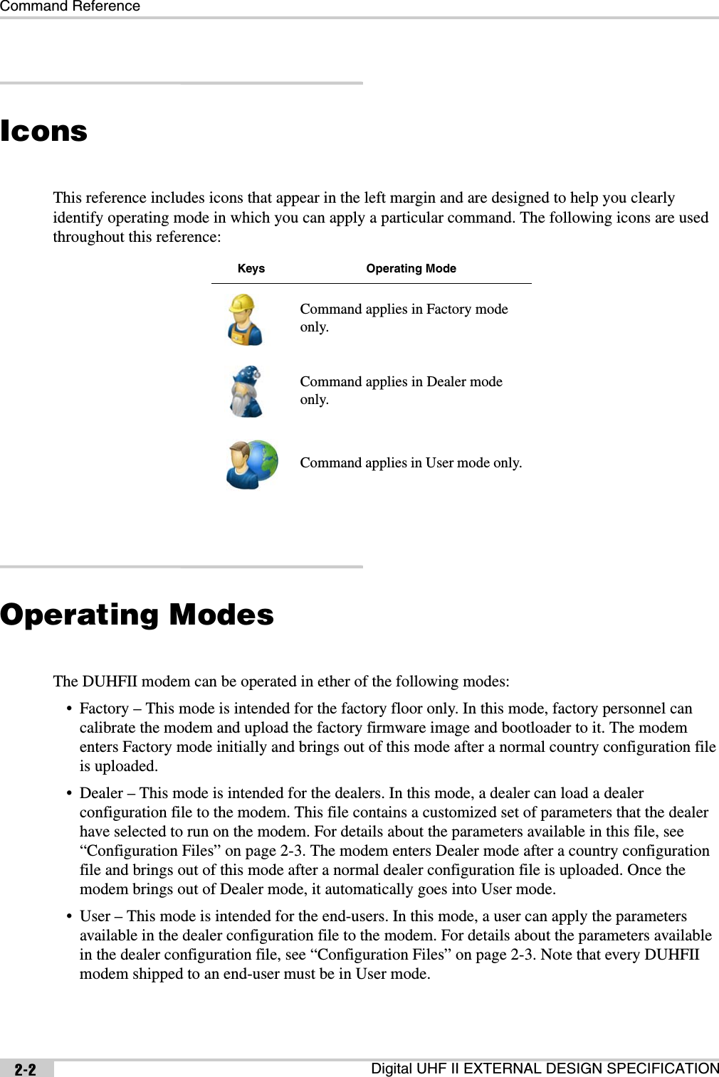
![Command ReferenceDigital UHF II EXTERNAL DESIGN SPECIFICATION2-4Country configuration fileThe country configuration file limits the range of allowed frequencies depending on the allocation of RF bands in a specific country (region). It allows up to four contingent frequency ranges, each with its own maximum output power and channel spacings. { t_U_Channels chan; unsigned int crc32;} t_User_Channels;typedef struct{ unsigned int DCFG; // 0x47464344 = DCFG signature unsigned short version; // = 0 unsigned short number_of_channels; // 0-64 variable size structure char callsign[32]; // zero terminated string t_User_Channels item[64]; unsigned int crc32; // The CRC32 is a standard CRC with a// polynomial of 0x04C11DB7, an initial// value of 0xFFFFFFFF and an inverted// output. The same algorithm is used in// ZIP and RAR archives as well as in the// ITU V.42 standard.} t_DealerConfig;typedef struct{ unsigned int start_freq; // Hz, 0 if unused unsigned int stop_freq; // Hz, 0 if unused unsigned int spacing_enable_mask; // 0x00000001 - 25kHz, // 0x00000002 - 12.5kHz,// 0x00000004 - 20kHz short reserved1; // = 0 char reserved2; // = 0 char max_power; // dBm, 10-30} t_Freq_Ranges;typedef struct{ unsigned int CCFG; // 0x47464344 = CCFG signature unsigned short version; // = 0, incompatible modifications will have// different number unsigned short reserved; // = 0 t_Freq_Ranges band[4]; // fixed size, not used ranges should be// zero](https://usermanual.wiki/Topcon-America/100926.User-s-Manual/User-Guide-1729078-Page-14.png)


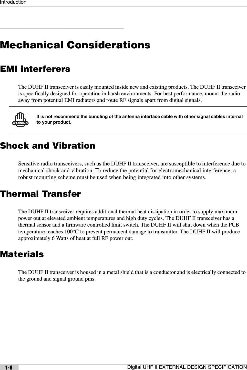
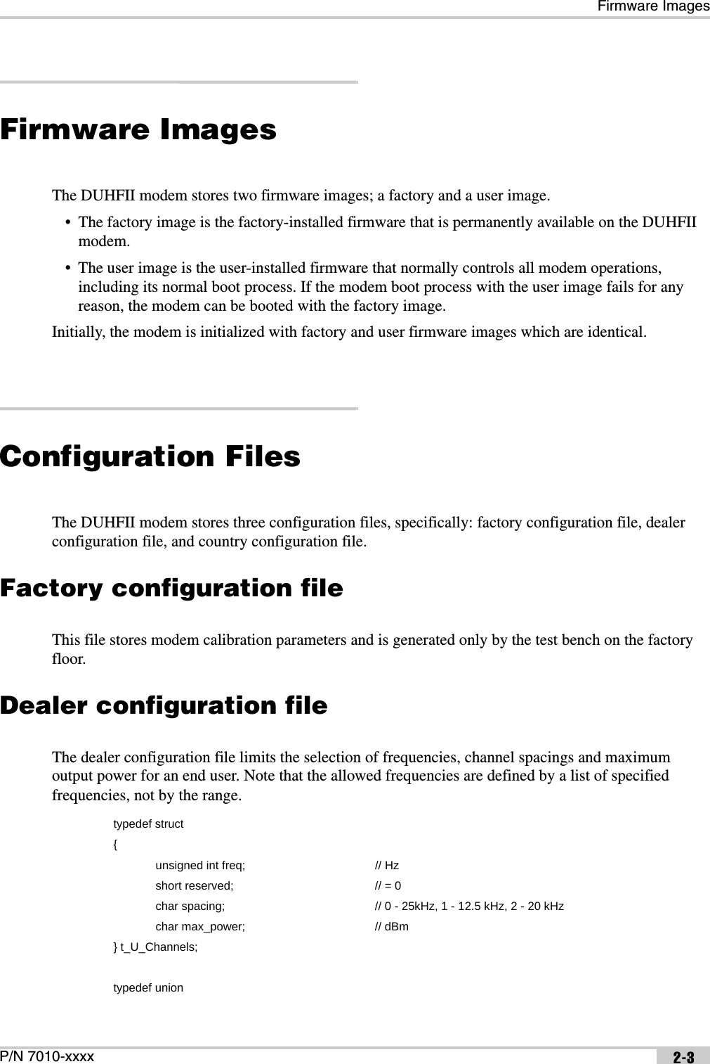
![Command ReferenceDigital UHF II EXTERNAL DESIGN SPECIFICATION2-8LINK Subcommands (Continued):PWRBPWRWDescription: Specifies the output power in dBm.Access: read & writeValues: [10...30]Usage Guidelines:The restrictions from the country and/or dealer configuration files may apply.Although you may specify any output power within its range of allowed values, only the following values are factory-calibrated and thus recommended for use:10, 13, 17, 20, 23, 27, 30.Command Examples:LINK PWRBLINK PWRB 20History: This subcommand was introduced in the first release of firmware.Description: Specifies the output power in mW.Access: read & writeValues: [10...1000]Usage Guidelines:Reading will return a value rounded to the nearest integer value in mW.The restrictions from the country and/or dealer configuration files may apply.Although you may specify any output power within its range of allowed values, only the following values are factory-calibrated and thus recommended for use: 10, 20, 50, 100, 200, 500, 1000.Command Examples:LINK PWRWLINK PWRW 500History: This subcommand was introduced in the first release of firmware.](https://usermanual.wiki/Topcon-America/100926.User-s-Manual/User-Guide-1729078-Page-18.png)
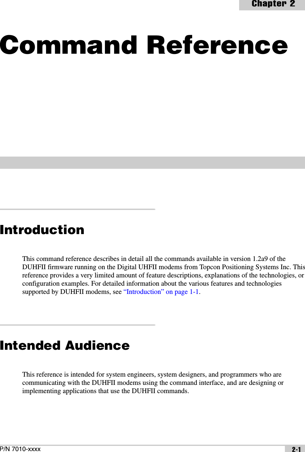
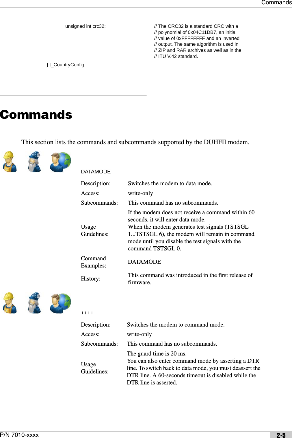
![CommandsP/N 7010-xxxx 2-9LINK Subcommands (Continued):SPACECHANUCHANDescription: Specifies the channel spacing in kHz.Access: read & writeValues:0 – 25 kHz1 – 12.5 kHz2 – 20 kHzUsage Guidelines:The restrictions from the country and/or dealer configuration files may apply.Command Examples:LINK SPACELINK SPACE 1History: This subcommand was introduced in the first release of firmware.Description: Specifies the frequency channel.Access: read & writeValues: [1...9601]Usage Guidelines:For 25 and 12.5 kHz spacings, the following formula is used to relate the frequency and its frequency channel: FRQ=410000000+(n-1)*6250, where n is the frequency channel.For 20 kHz spacing, the following formula is used to relate the frequency and its frequency channel: FRQ=410000000+(n-10001)*5000, where n is the frequency channel.The restrictions from the country and/or dealer configuration files may apply.Command Examples:LINK CHANLINK CHAN 1History: This subcommand was introduced in the first release of firmware.Description: Selects channel settings from the dealer list.Access: read & writeValues: [0...63]Usage Guidelines: This subcommand has no usage guidelines.Command Examples:LINK UCHANLINK UCHAN 12History: This subcommand was introduced in the first release of firmware.](https://usermanual.wiki/Topcon-America/100926.User-s-Manual/User-Guide-1729078-Page-19.png)
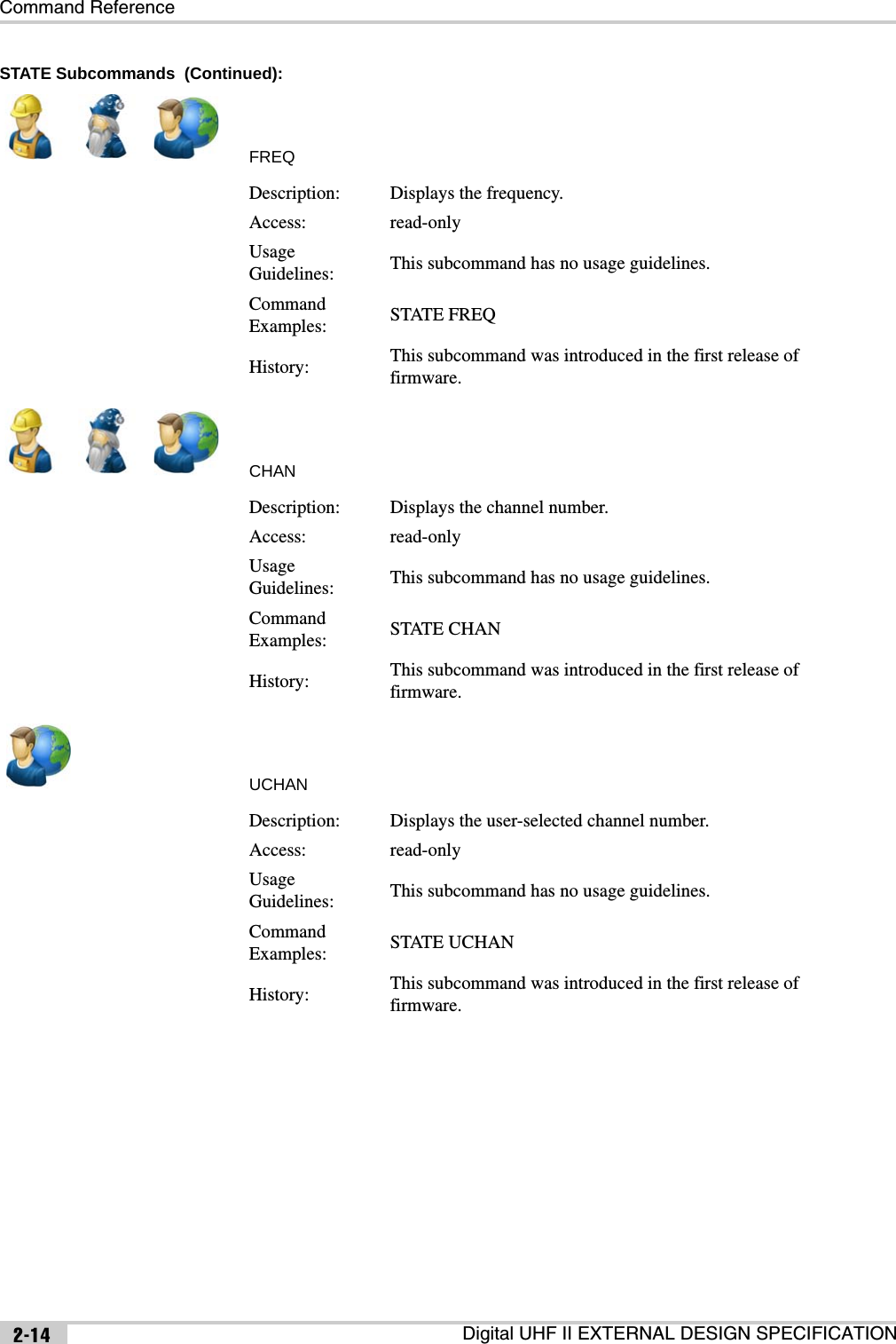
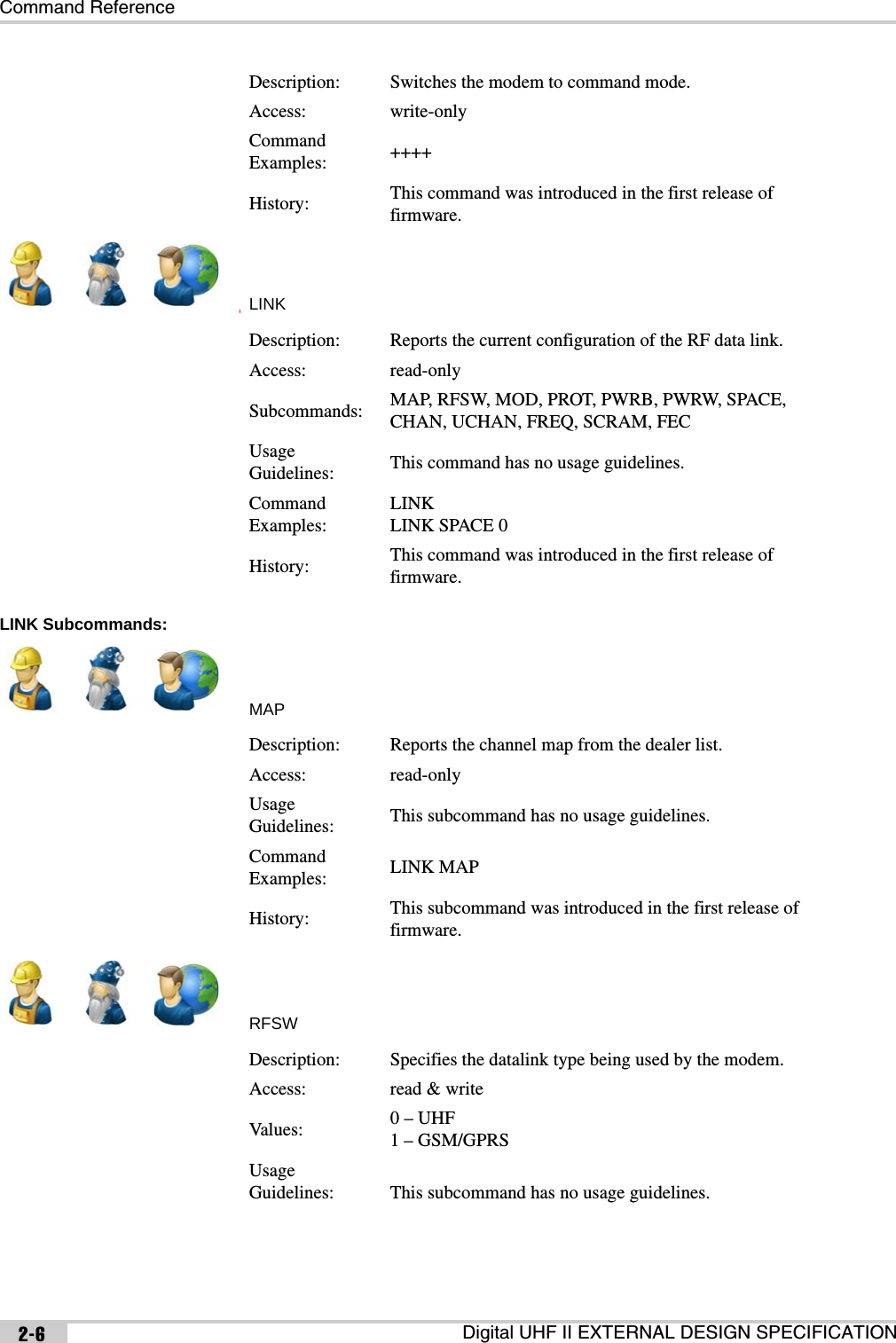
![Command ReferenceDigital UHF II EXTERNAL DESIGN SPECIFICATION2-10LINK Subcommands (Continued):FREQSCRAMFECDescription: Specifies the channel frequency.Access: read & writeValues: [390000000...480000000]Usage Guidelines:The frequency will be rounded to the nearest available channel depending on channel spacing. An actual frequency range will be defined by Country Configuration.The restrictions from the country and/or dealer configuration files may apply.Command Examples:LINK FREQLINK FREQ 420000000History: This subcommand was introduced in the first release of firmware.Description: Configures scrambling.Access: read & writeValues:[0...255]0 – disabled[1...255] – scrambling enabledUsage Guidelines:Scrambling is always enabled for TrimTalk.Scrambling is always disabled for Satel.Command Examples:LINK SCRAMLINK SCRAM 1History: This subcommand was introduced in the first release of firmware.Description: Configures forward error correction.Access: read & writeValues: 0 – disabled1 – enabledUsage Guidelines:FEC is supported for PDL and Satel.FEC is always disabled for TrimTalk.Command Examples:LINK FECLINK FEC 1History: This subcommand was introduced in the first release of firmware.](https://usermanual.wiki/Topcon-America/100926.User-s-Manual/User-Guide-1729078-Page-20.png)


![Command ReferenceDigital UHF II EXTERNAL DESIGN SPECIFICATION2-22PROTIMETCXOALCDescription: Configures the protocol timeout.Access: read & writeValues: [10...255]Subcommands: This command has no subcommands.Usage Guidelines: This command has no usage guidelines.Command Examples: PROTIME 15History: This command was introduced in the first release of firmware.Description: Adjusts oscillator offset.Access: read & writeValues: [0...32]Subcommands: This command has no subcommands.Usage Guidelines: This command has no usage guidelines.Command Examples: TCXO 20History: This command was introduced in the first release of firmware.Description: Configures transmitter gains.Access: read-onlySubcommands: A, B, D, X, YUsage Guidelines: This command has no usage guidelines.Command Examples: ALCHistory: This command was introduced in the first release of firmware.](https://usermanual.wiki/Topcon-America/100926.User-s-Manual/User-Guide-1729078-Page-32.png)
![CommandsP/N 7010-xxxx 2-23ALC Subcommands:ABDDescription: Configures the pre-amplifier gain.Access: read & writeValues: [0...31]Usage Guidelines: This subcommand has no usage guidelines.Command Examples:ALC AALC A 12History: This subcommand was introduced in the first release of firmware.Description: Configures the amplifier gain.Access: read & writeValues: [0...32]Usage Guidelines: This subcommand has no usage guidelines.Command Examples:ALC BALC B 10History: This subcommand was introduced in the first release of firmware.Description: Configures the DAC gain.Access: read & writeValues: [0...32767]Usage Guidelines: This subcommand has no usage guidelines.Command Examples:ALC DALC D 15343History: This subcommand was introduced in the first release of firmware.](https://usermanual.wiki/Topcon-America/100926.User-s-Manual/User-Guide-1729078-Page-33.png)
![Command ReferenceDigital UHF II EXTERNAL DESIGN SPECIFICATION2-24ALC Subcommands (Continued):XYCSAVEDescription: Configures the TX modulator offset.Access: read & writeValues: [-4096...4095]Usage Guidelines: This subcommand has no usage guidelines.Command Examples:ALC XALC X -4090History: This subcommand was introduced in the first release of firmware.Description: Configures the TX modulator offset.Access: read & writeValues: [-4096...4095]Usage Guidelines: This subcommand has no usage guidelines.Command Examples:ALC YALC Y 4090History: This subcommand was introduced in the first release of firmware.Description: Stores the current ALC values to the calibration table.Access: write-onlySubcommands: This command has no subcommands.Usage Guidelines: Used for manual calibration.Command Examples: CSAVEHistory: This command was introduced in the first release of firmware.](https://usermanual.wiki/Topcon-America/100926.User-s-Manual/User-Guide-1729078-Page-34.png)
![CommandsP/N 7010-xxxx 2-25TSTSGLFCSFCS Subcommands:CHANCLRDescription: Configures test signals.Access: write-onlyValues: [0...6]Subcommands: This command has no subcommands.Usage Guidelines: This command has no usage guidelines.Command Examples: TSTSGL 3History: This command was introduced in the first release of firmware.Description: Configures the protocol timeout.Access: read-onlySubcommands: CHANCLR, NETID, RXLT, BI, BDT, CHANON, CHANOFF, RSSIUsage Guidelines: This command applies to Satel protocol only.Command Examples: FCSHistory: This command was introduced in the first release of firmware.Description: Clears the channel list.Access: write-onlyUsage Guidelines: This subcommand has no usage guidelines.Command Examples: FCS CHANCLRHistory: This subcommand was introduced in the first release of firmware.](https://usermanual.wiki/Topcon-America/100926.User-s-Manual/User-Guide-1729078-Page-35.png)
![Command ReferenceDigital UHF II EXTERNAL DESIGN SPECIFICATION2-26FCS Subcommands (Continued):NETIDRXLTBIDescription: Configures network ID.Access: read & writeValues: [0x0000...0xFFFF]Usage Guidelines: This subcommand has no usage guidelines.Command Examples: FCS NETID 0x0000History: This subcommand was introduced in the first release of firmware.Description: Configures the RX listen timeout.Access: read & writeValues: [0...65535]Usage Guidelines: This subcommand has no usage guidelines.Command Examples: FCS RXLT 30History: This subcommand was introduced in the first release of firmware.Description: Configures the beacon interval.Access: read & writeValues: [0...65535]Usage Guidelines: This subcommand has no usage guidelines.Command Examples: FCS BI 50History: This subcommand was introduced in the first release of firmware.](https://usermanual.wiki/Topcon-America/100926.User-s-Manual/User-Guide-1729078-Page-36.png)
![CommandsP/N 7010-xxxx 2-27FCS Subcommands (Continued):BDTCHANONCHANOFFDescription: Configures the beacon disable timeout.Access: read & writeValues: [0...65535]Usage Guidelines: This subcommand has no usage guidelines.Command Examples: FCS BDT 60History: This subcommand was introduced in the first release of firmware.Description: Enables FCS for the selected channel.Access: write-onlyValues: [0...47]Usage Guidelines: This subcommand has no usage guidelines.Command Examples: FCS CHANON 9History: This subcommand was introduced in the first release of firmware.Description: Disables FCS for the selected channel.Access: write-onlyValues: [0...47]Usage Guidelines: This subcommand has no usage guidelines.Command Examples: FCS CHANOFF 9History: This subcommand was introduced in the first release of firmware.](https://usermanual.wiki/Topcon-America/100926.User-s-Manual/User-Guide-1729078-Page-37.png)
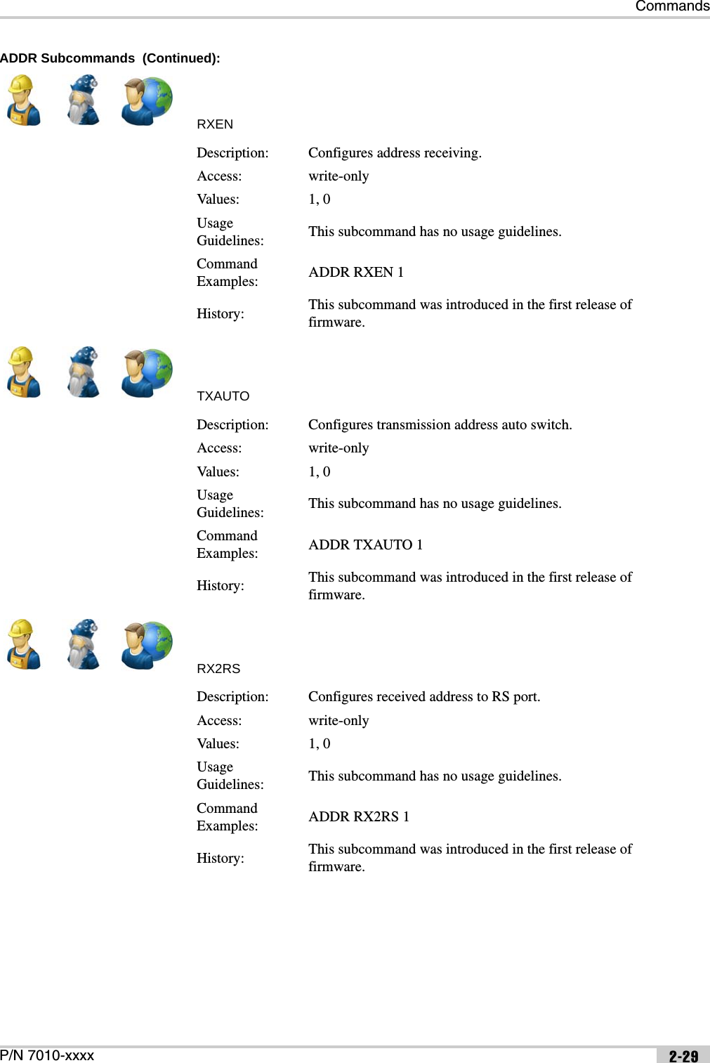
![Command ReferenceDigital UHF II EXTERNAL DESIGN SPECIFICATION2-28FCS Subcommands (Continued):RSSIADDRADDR Subcommands:TXENDescription: Configures the RSSI threshold.Access: read & writeValues: [80...118]Usage Guidelines: This subcommand has no usage guidelines.Command Examples: FCS RSSI 95History: This subcommand was introduced in the first release of firmware.Description: Displays Satel protocol routing.Access: read-onlySubcommands: TXEN, RXEN, TXAUTO, RX2RS, TXP, RXP, TXS, RXSUsage Guidelines: This command applies to Satel protocol only.Command Examples: ADDRHistory: This command was introduced in the first release of firmware.Description: Configures address transmission.Access: write-onlyValues: 1, 0Usage Guidelines: This subcommand has no usage guidelines.Command Examples: ADDR TXEN 1History: This subcommand was introduced in the first release of firmware.](https://usermanual.wiki/Topcon-America/100926.User-s-Manual/User-Guide-1729078-Page-38.png)

![Command ReferenceDigital UHF II EXTERNAL DESIGN SPECIFICATION2-30ADDR Subcommands (Continued):TXPRXPTXSDescription: Configures the transmission primary address.Access: read & writeValues: [0x0000...0xFFFF]Usage Guidelines: This subcommand has no usage guidelines.Command Examples: ADDR TXP 0x0000History: This subcommand was introduced in the first release of firmware.Description: Configures the receiving primary address.Access: read & writeValues: [0x0000...0xFFFF]Usage Guidelines: This subcommand has no usage guidelines.Command Examples: ADDR RXP 0x0000History: This subcommand was introduced in the first release of firmware.Description: Configures the transmission secondary address.Access: read & writeValues: [0x0000...0xFFFF]Usage Guidelines: This subcommand has no usage guidelines.Command Examples: ADDR TXS 0x0001History: This subcommand was introduced in the first release of firmware.](https://usermanual.wiki/Topcon-America/100926.User-s-Manual/User-Guide-1729078-Page-40.png)
![CommandsP/N 7010-xxxx 2-31ADDR Subcommands (Continued):RXSTXDELAYHELPDescription: Configures the receiving secondary address.Access: read & writeValues: [0x0000...0xFFFF]Usage Guidelines: This subcommand has no usage guidelines.Command Examples: ADDR RXS 0x0002History: This subcommand was introduced in the first release of firmware.Description: Configures transmit delay.Access: read & writeValues: [0...65535]Subcommands: This command has no subcommands.Usage Guidelines: This command has no usage guidelines.Command Examples: TXDELAY 20History: This command was introduced in the first release of firmware.Description: Displays commands and their description.Access: read-onlySubcommands: This command has no subcommands.Usage Guidelines: This command has no usage guidelines.Command Examples: HELPHistory: This command was introduced in the first release of firmware.](https://usermanual.wiki/Topcon-America/100926.User-s-Manual/User-Guide-1729078-Page-41.png)


![Command ReferenceDigital UHF II EXTERNAL DESIGN SPECIFICATION2-4Country configuration fileThe country configuration file limits the range of allowed frequencies depending on the allocation of RF bands in a specific country (region). It allows up to four contingent frequency ranges, each with its own maximum output power and channel spacings. { t_U_Channels chan; unsigned int crc32;} t_User_Channels;typedef struct{ unsigned int DCFG; // 0x47464344 = DCFG signature unsigned short version; // = 0 unsigned short number_of_channels; // 0-64 variable size structure char callsign[32]; // zero terminated string t_User_Channels item[64]; unsigned int crc32; // The CRC32 is a standard CRC with a// polynomial of 0x04C11DB7, an initial// value of 0xFFFFFFFF and an inverted// output. The same algorithm is used in// ZIP and RAR archives as well as in the// ITU V.42 standard.} t_DealerConfig;typedef struct{ unsigned int start_freq; // Hz, 0 if unused unsigned int stop_freq; // Hz, 0 if unused unsigned int spacing_enable_mask; // 0x00000001 - 25kHz, // 0x00000002 - 12.5kHz,// 0x00000004 - 20kHz short reserved1; // = 0 char reserved2; // = 0 char max_power; // dBm, 10-30} t_Freq_Ranges;typedef struct{ unsigned int CCFG; // 0x47464344 = CCFG signature unsigned short version; // = 0, incompatible modifications will have// different number unsigned short reserved; // = 0 t_Freq_Ranges band[4]; // fixed size, not used ranges should be// zero](https://usermanual.wiki/Topcon-America/100926.Users-Manual/User-Guide-1729165-Page-14.png)
![Command ReferenceDigital UHF II EXTERNAL DESIGN SPECIFICATION2-8LINK Subcommands (Continued):PWRBPWRWDescription: Specifies the output power in dBm.Access: read & writeValues: [10...30]Usage Guidelines:The restrictions from the country and/or dealer configuration files may apply.Although you may specify any output power within its range of allowed values, only the following values are factory-calibrated and thus recommended for use:10, 13, 17, 20, 23, 27, 30.Command Examples:LINK PWRBLINK PWRB 20History: This subcommand was introduced in the first release of firmware.Description: Specifies the output power in mW.Access: read & writeValues: [10...1000]Usage Guidelines:Reading will return a value rounded to the nearest integer value in mW.The restrictions from the country and/or dealer configuration files may apply.Although you may specify any output power within its range of allowed values, only the following values are factory-calibrated and thus recommended for use: 10, 20, 50, 100, 200, 500, 1000.Command Examples:LINK PWRWLINK PWRW 500History: This subcommand was introduced in the first release of firmware.](https://usermanual.wiki/Topcon-America/100926.Users-Manual/User-Guide-1729165-Page-18.png)
![CommandsP/N 7010-xxxx 2-9LINK Subcommands (Continued):SPACECHANUCHANDescription: Specifies the channel spacing in kHz.Access: read & writeValues:0 – 25 kHz1 – 12.5 kHz2 – 20 kHzUsage Guidelines:The restrictions from the country and/or dealer configuration files may apply.Command Examples:LINK SPACELINK SPACE 1History: This subcommand was introduced in the first release of firmware.Description: Specifies the frequency channel.Access: read & writeValues: [1...9601]Usage Guidelines:For 25 and 12.5 kHz spacings, the following formula is used to relate the frequency and its frequency channel: FRQ=410000000+(n-1)*6250, where n is the frequency channel.For 20 kHz spacing, the following formula is used to relate the frequency and its frequency channel: FRQ=410000000+(n-10001)*5000, where n is the frequency channel.The restrictions from the country and/or dealer configuration files may apply.Command Examples:LINK CHANLINK CHAN 1History: This subcommand was introduced in the first release of firmware.Description: Selects channel settings from the dealer list.Access: read & writeValues: [0...63]Usage Guidelines: This subcommand has no usage guidelines.Command Examples:LINK UCHANLINK UCHAN 12History: This subcommand was introduced in the first release of firmware.](https://usermanual.wiki/Topcon-America/100926.Users-Manual/User-Guide-1729165-Page-19.png)
![Command ReferenceDigital UHF II EXTERNAL DESIGN SPECIFICATION2-10LINK Subcommands (Continued):FREQSCRAMFECDescription: Specifies the channel frequency.Access: read & writeValues: [390000000...480000000]Usage Guidelines:The frequency will be rounded to the nearest available channel depending on channel spacing. An actual frequency range will be defined by Country Configuration.The restrictions from the country and/or dealer configuration files may apply.Command Examples:LINK FREQLINK FREQ 420000000History: This subcommand was introduced in the first release of firmware.Description: Configures scrambling.Access: read & writeValues:[0...255]0 – disabled[1...255] – scrambling enabledUsage Guidelines:Scrambling is always enabled for TrimTalk.Scrambling is always disabled for Satel.Command Examples:LINK SCRAMLINK SCRAM 1History: This subcommand was introduced in the first release of firmware.Description: Configures forward error correction.Access: read & writeValues: 0 – disabled1 – enabledUsage Guidelines:FEC is supported for PDL and Satel.FEC is always disabled for TrimTalk.Command Examples:LINK FECLINK FEC 1History: This subcommand was introduced in the first release of firmware.](https://usermanual.wiki/Topcon-America/100926.Users-Manual/User-Guide-1729165-Page-20.png)


![Command ReferenceDigital UHF II EXTERNAL DESIGN SPECIFICATION2-22PROTIMETCXOALCDescription: Configures the protocol timeout.Access: read & writeValues: [10...255]Subcommands: This command has no subcommands.Usage Guidelines: This command has no usage guidelines.Command Examples: PROTIME 15History: This command was introduced in the first release of firmware.Description: Adjusts oscillator offset.Access: read & writeValues: [0...32]Subcommands: This command has no subcommands.Usage Guidelines: This command has no usage guidelines.Command Examples: TCXO 20History: This command was introduced in the first release of firmware.Description: Configures transmitter gains.Access: read-onlySubcommands: A, B, D, X, YUsage Guidelines: This command has no usage guidelines.Command Examples: ALCHistory: This command was introduced in the first release of firmware.](https://usermanual.wiki/Topcon-America/100926.Users-Manual/User-Guide-1729165-Page-32.png)
![CommandsP/N 7010-xxxx 2-23ALC Subcommands:ABDDescription: Configures the pre-amplifier gain.Access: read & writeValues: [0...31]Usage Guidelines: This subcommand has no usage guidelines.Command Examples:ALC AALC A 12History: This subcommand was introduced in the first release of firmware.Description: Configures the amplifier gain.Access: read & writeValues: [0...32]Usage Guidelines: This subcommand has no usage guidelines.Command Examples:ALC BALC B 10History: This subcommand was introduced in the first release of firmware.Description: Configures the DAC gain.Access: read & writeValues: [0...32767]Usage Guidelines: This subcommand has no usage guidelines.Command Examples:ALC DALC D 15343History: This subcommand was introduced in the first release of firmware.](https://usermanual.wiki/Topcon-America/100926.Users-Manual/User-Guide-1729165-Page-33.png)
![Command ReferenceDigital UHF II EXTERNAL DESIGN SPECIFICATION2-24ALC Subcommands (Continued):XYCSAVEDescription: Configures the TX modulator offset.Access: read & writeValues: [-4096...4095]Usage Guidelines: This subcommand has no usage guidelines.Command Examples:ALC XALC X -4090History: This subcommand was introduced in the first release of firmware.Description: Configures the TX modulator offset.Access: read & writeValues: [-4096...4095]Usage Guidelines: This subcommand has no usage guidelines.Command Examples:ALC YALC Y 4090History: This subcommand was introduced in the first release of firmware.Description: Stores the current ALC values to the calibration table.Access: write-onlySubcommands: This command has no subcommands.Usage Guidelines: Used for manual calibration.Command Examples: CSAVEHistory: This command was introduced in the first release of firmware.](https://usermanual.wiki/Topcon-America/100926.Users-Manual/User-Guide-1729165-Page-34.png)
![CommandsP/N 7010-xxxx 2-25TSTSGLFCSFCS Subcommands:CHANCLRDescription: Configures test signals.Access: write-onlyValues: [0...6]Subcommands: This command has no subcommands.Usage Guidelines: This command has no usage guidelines.Command Examples: TSTSGL 3History: This command was introduced in the first release of firmware.Description: Configures the protocol timeout.Access: read-onlySubcommands: CHANCLR, NETID, RXLT, BI, BDT, CHANON, CHANOFF, RSSIUsage Guidelines: This command applies to Satel protocol only.Command Examples: FCSHistory: This command was introduced in the first release of firmware.Description: Clears the channel list.Access: write-onlyUsage Guidelines: This subcommand has no usage guidelines.Command Examples: FCS CHANCLRHistory: This subcommand was introduced in the first release of firmware.](https://usermanual.wiki/Topcon-America/100926.Users-Manual/User-Guide-1729165-Page-35.png)
![Command ReferenceDigital UHF II EXTERNAL DESIGN SPECIFICATION2-26FCS Subcommands (Continued):NETIDRXLTBIDescription: Configures network ID.Access: read & writeValues: [0x0000...0xFFFF]Usage Guidelines: This subcommand has no usage guidelines.Command Examples: FCS NETID 0x0000History: This subcommand was introduced in the first release of firmware.Description: Configures the RX listen timeout.Access: read & writeValues: [0...65535]Usage Guidelines: This subcommand has no usage guidelines.Command Examples: FCS RXLT 30History: This subcommand was introduced in the first release of firmware.Description: Configures the beacon interval.Access: read & writeValues: [0...65535]Usage Guidelines: This subcommand has no usage guidelines.Command Examples: FCS BI 50History: This subcommand was introduced in the first release of firmware.](https://usermanual.wiki/Topcon-America/100926.Users-Manual/User-Guide-1729165-Page-36.png)
![CommandsP/N 7010-xxxx 2-27FCS Subcommands (Continued):BDTCHANONCHANOFFDescription: Configures the beacon disable timeout.Access: read & writeValues: [0...65535]Usage Guidelines: This subcommand has no usage guidelines.Command Examples: FCS BDT 60History: This subcommand was introduced in the first release of firmware.Description: Enables FCS for the selected channel.Access: write-onlyValues: [0...47]Usage Guidelines: This subcommand has no usage guidelines.Command Examples: FCS CHANON 9History: This subcommand was introduced in the first release of firmware.Description: Disables FCS for the selected channel.Access: write-onlyValues: [0...47]Usage Guidelines: This subcommand has no usage guidelines.Command Examples: FCS CHANOFF 9History: This subcommand was introduced in the first release of firmware.](https://usermanual.wiki/Topcon-America/100926.Users-Manual/User-Guide-1729165-Page-37.png)
![Command ReferenceDigital UHF II EXTERNAL DESIGN SPECIFICATION2-28FCS Subcommands (Continued):RSSIADDRADDR Subcommands:TXENDescription: Configures the RSSI threshold.Access: read & writeValues: [80...118]Usage Guidelines: This subcommand has no usage guidelines.Command Examples: FCS RSSI 95History: This subcommand was introduced in the first release of firmware.Description: Displays Satel protocol routing.Access: read-onlySubcommands: TXEN, RXEN, TXAUTO, RX2RS, TXP, RXP, TXS, RXSUsage Guidelines: This command applies to Satel protocol only.Command Examples: ADDRHistory: This command was introduced in the first release of firmware.Description: Configures address transmission.Access: write-onlyValues: 1, 0Usage Guidelines: This subcommand has no usage guidelines.Command Examples: ADDR TXEN 1History: This subcommand was introduced in the first release of firmware.](https://usermanual.wiki/Topcon-America/100926.Users-Manual/User-Guide-1729165-Page-38.png)
![Command ReferenceDigital UHF II EXTERNAL DESIGN SPECIFICATION2-30ADDR Subcommands (Continued):TXPRXPTXSDescription: Configures the transmission primary address.Access: read & writeValues: [0x0000...0xFFFF]Usage Guidelines: This subcommand has no usage guidelines.Command Examples: ADDR TXP 0x0000History: This subcommand was introduced in the first release of firmware.Description: Configures the receiving primary address.Access: read & writeValues: [0x0000...0xFFFF]Usage Guidelines: This subcommand has no usage guidelines.Command Examples: ADDR RXP 0x0000History: This subcommand was introduced in the first release of firmware.Description: Configures the transmission secondary address.Access: read & writeValues: [0x0000...0xFFFF]Usage Guidelines: This subcommand has no usage guidelines.Command Examples: ADDR TXS 0x0001History: This subcommand was introduced in the first release of firmware.](https://usermanual.wiki/Topcon-America/100926.Users-Manual/User-Guide-1729165-Page-40.png)
![CommandsP/N 7010-xxxx 2-31ADDR Subcommands (Continued):RXSTXDELAYHELPDescription: Configures the receiving secondary address.Access: read & writeValues: [0x0000...0xFFFF]Usage Guidelines: This subcommand has no usage guidelines.Command Examples: ADDR RXS 0x0002History: This subcommand was introduced in the first release of firmware.Description: Configures transmit delay.Access: read & writeValues: [0...65535]Subcommands: This command has no subcommands.Usage Guidelines: This command has no usage guidelines.Command Examples: TXDELAY 20History: This command was introduced in the first release of firmware.Description: Displays commands and their description.Access: read-onlySubcommands: This command has no subcommands.Usage Guidelines: This command has no usage guidelines.Command Examples: HELPHistory: This command was introduced in the first release of firmware.](https://usermanual.wiki/Topcon-America/100926.Users-Manual/User-Guide-1729165-Page-41.png)