Topcon America 100926 DIG UHF-II Radio Module User Manual COMPREHENSIVE INSTALLATION INSTRUCTIONS
Topcon America Corporation DIG UHF-II Radio Module COMPREHENSIVE INSTALLATION INSTRUCTIONS
Contents
- 1. User's Manual
- 2. Users Manual
- 3. COMPREHENSIVE INSTALLATION INSTRUCTIONS
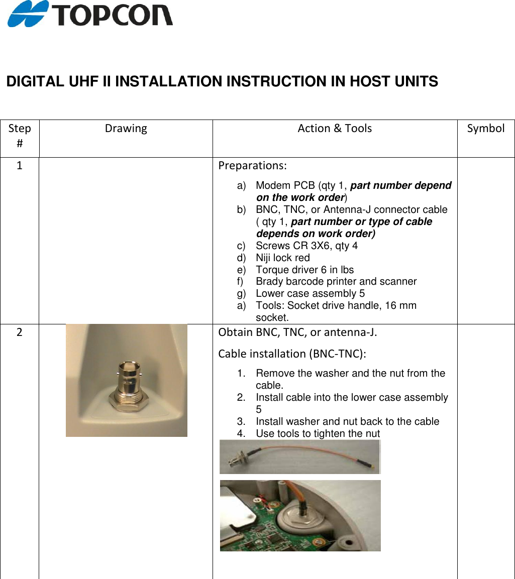
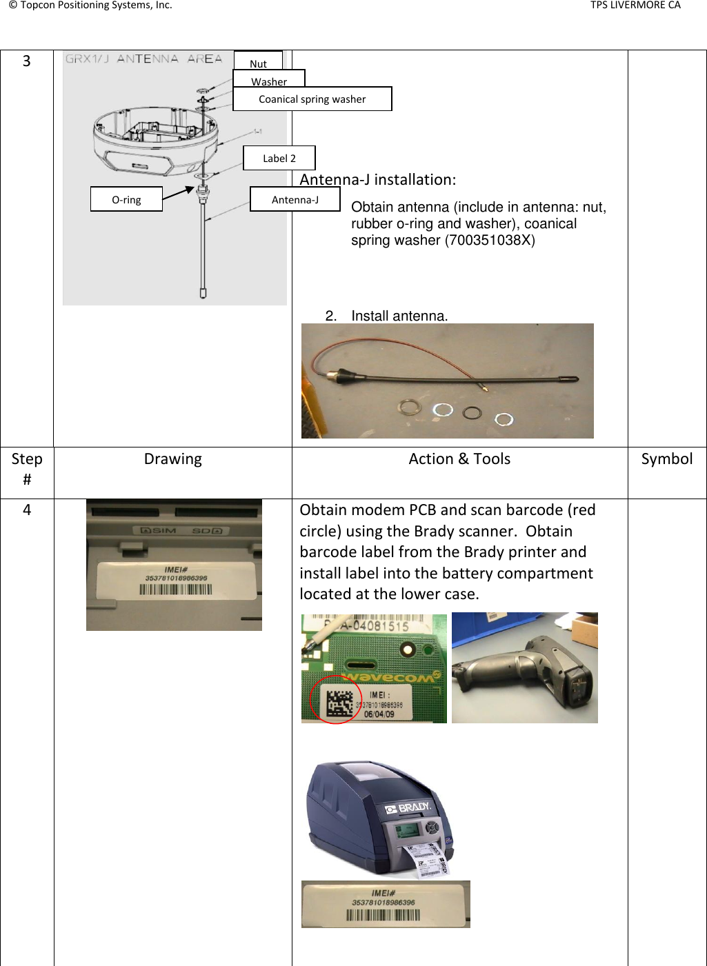
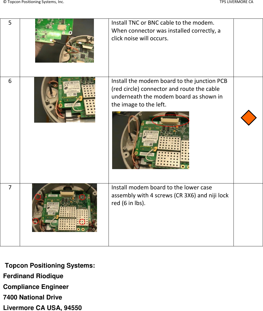
COMPREHENSIVE INSTALLATION INSTRUCTIONS