Topcon America 100926 DIG UHF-II Radio Module User Manual COMPREHENSIVE INSTALLATION INSTRUCTIONS
Topcon America Corporation DIG UHF-II Radio Module COMPREHENSIVE INSTALLATION INSTRUCTIONS
Contents
- 1. User's Manual
- 2. Users Manual
- 3. COMPREHENSIVE INSTALLATION INSTRUCTIONS
COMPREHENSIVE INSTALLATION INSTRUCTIONS
DIGITAL UHF II INSTALLATION INSTRUCTION IN HOST UNITS
Step
#
Drawing
Action & Tools
Symbol
1
Preparations:
a) Modem PCB (qty 1, part number depend
on the work order)
b) BNC, TNC, or Antenna-J connector cable
( qty 1, part number or type of cable
depends on work order)
c) Screws CR 3X6, qty 4
d) Niji lock red
e) Torque driver 6 in lbs
f) Brady barcode printer and scanner
g) Lower case assembly 5
a) Tools: Socket drive handle, 16 mm
socket.
2
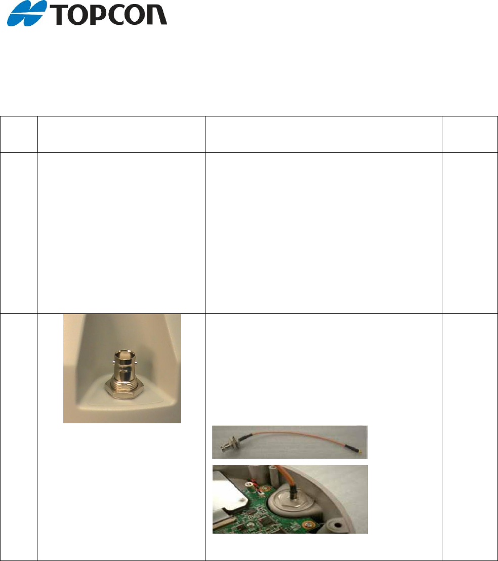
Obtain BNC, TNC, or antenna-J.
Cable installation (BNC-TNC):
1. Remove the washer and the nut from the
cable.
2. Install cable into the lower case assembly
5
3. Install washer and nut back to the cable
4. Use tools to tighten the nut
© Topcon Positioning Systems, Inc. TPS LIVERMORE CA
3
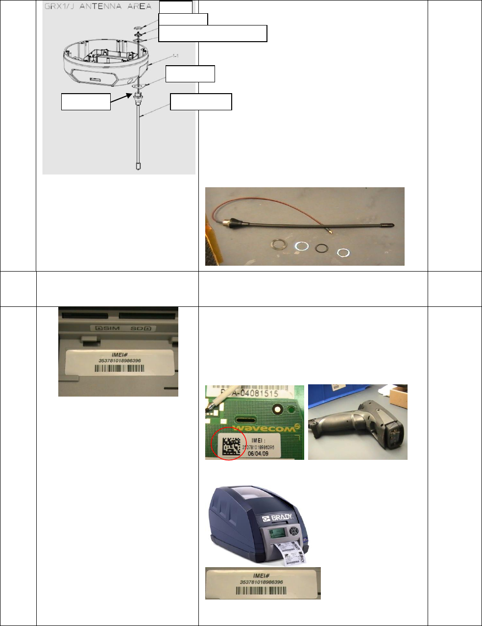
Antenna-J installation:
1. Obtain antenna (include in antenna: nut,
rubber o-ring and washer), coanical
spring washer (700351038X)
2. Install antenna.
Step
#
Drawing
Action & Tools
Symbol
4
Obtain modem PCB and scan barcode (red
circle) using the Brady scanner. Obtain
barcode label from the Brady printer and
install label into the battery compartment
located at the lower case.
Nut
Washer
Coanical spring washer
Label 2
Antenna-J
O-ring
© Topcon Positioning Systems, Inc. TPS LIVERMORE CA
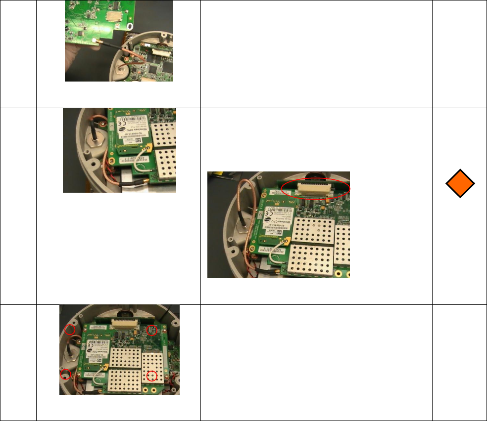
5
Install TNC or BNC cable to the modem.
When connector was installed correctly, a
click noise will occurs.
6
Install the modem board to the junction PCB
(red circle) connector and route the cable
underneath the modem board as shown in
the image to the left.
7
Install modem board to the lower case
assembly with 4 screws (CR 3X6) and niji lock
red (6 in lbs).
Topcon Positioning Systems:
Ferdinand Riodique
Compliance Engineer
7400 National Drive
Livermore CA USA, 94550