Topcon America 100926 DIG UHF-II Radio Module User Manual DUHFII ig
Topcon America Corporation DIG UHF-II Radio Module DUHFII ig
Contents
- 1. User's Manual
- 2. Users Manual
- 3. COMPREHENSIVE INSTALLATION INSTRUCTIONS
User's Manual

Digital UHF II Radio Module
EXTERNAL DESIGN SPECIFICATION
Part Number 7010-xxxx
Rev. A
©Copyright Topcon Positioning Systems, Inc.
December, 2011
All contents in this manual are copyrighted by Topcon Positioning System, Inc. All rights reserved. The information
contained herein may not be used, accessed, copied, stored, displayed, sold, modified, published, or distributed, or
otherwise reproduced without express written consent from Topcon.

P/N 7010-xxxx i
TOC
Table of Contents
1 Introduction 1-1
Overview 1-1
Product Features 1-2
Operating Band, Channel Spacing, and Output Power 1-2
Modulation Technique 1-2
Physical Interfaces 1-2
Serial Data Interface 1-2
Link Status Indicators 1-3
Power Interface 1-3
RF Interface 1-3
Bluetooth Interface 1-3
Hardware Architecture 1-4
Functional Requirements 1-4
Electromagnetic Compliance 1-4
Electromagnetic Compatibility 1-5
Shielding Considerations 1-5
Frequency Planning 1-5
Mechanical Considerations 1-6
EMI interferers 1-6
Shock and Vibration 1-6
Thermal Transfer 1-6

Table of Contents
Digital UHF II EXTERNAL DESIGN SPECIFICATION
ii
Materials 1-6
2 Command Reference 2-1
Introduction 2-1
Intended Audience 2-1
Icons 2-2
Operating Modes 2-2
Firmware Images 2-3
Configuration Files 2-3
Factory configuration file 2-3
Dealer configuration file 2-3
Country configuration file 2-4
Commands 2-5
3 Specifications 3-1
Board Specifications 3-1
Interface Connector 3-4

P/N 7010-xxxx 1-1
Chapter 1
Introduction
Overview
DUHFII is a half duplex, UHF Radio Modem with built-in GSM/GPRS (or CDMA, HSPA) module
and Bluetooth transceiver developed to be integrated in a Topcon receiver. It takes incoming data from
a Topcon receiver through the standard serial port (CMOS/TTL compatible), modulates it with GMSK,
or 4FSK modulations and transmits it at RF power output levels from 10mW/10dBm to 1W/30dBm.
With 4FSK modulation, it will deliver error-free data at up to 19.2 kbps over the air for the 25 kHz
channel spacing and 9.6 kbps for 12.5 kHz.
The carrier frequency is the UHF commercial band of 400 MHz to 470 MHz. Channel spacing at 25
kHz, 20 kHz and 12.5 kHz are supported. The UHF transceiver is also capable of receiving RF signals
through a 50 Ohm impedance external antenna port. These signals are demodulated and output to the
Topcon receiver.
The modem requires a regulated DC voltage power supply from +6 to +14VDC with a maximum
current draw of 1.1A at 6VDC.
The incoming data could be also sent over the cellular network using built-in GSM/GPRS (or CDMA,
3G) module if such operation mode is selected.
The radio settings can be done through the built-in Command Line interface (CLI), or through the
configuration and maintenance application software running on the PC – “TRU”.
Note: The cell module option is currently not available. References to the cell module option in this
manual are for future configurations that have not been released.

Introduction
Digital UHF II EXTERNAL DESIGN SPECIFICATION
1-2
Product Features
Operating Band, Channel Spacing, and Output
Power
The following are its key benefits:
1. Single radio system covers the whole UHF frequency band from 400 to 470 MHz;
2. User selectable channel spacing (25kHz, 20kHz or 12.5kHz);
3. User selectable Output power level for base unit (10mW/10dBm and 1W/30dBm);
4. Programmable to limit operation to given frequency range or list of channels, given channel
spacing, given output power, RX mode.
Modulation Technique
The design is based on high-level modulation techniques which include:
Physical Interfaces
Serial Data Interface
The serial Data Interface can be configured through the software to operate in half and full duplex
operating modes. RTS, CTS, and CD signals should be reserved on-board for future support of full
UART hardware handshake operation. This will provide the support of the wide range of different
standard and none-standard, user specific, Data Link interfaces.
Modulation Technique 12.5 kHz 25 kHz
GMSK – Minimal Shift Keying with Gaussian Filtering 4.8 kbps 9.6 kbps 4.8 kbps 9.6 kbps
4FSK – Four Level Frequency Shift Keying 9.6 kbps 19.2 kbps 9.6 kbps 19.2 kbps

Physical Interfaces
P/N 7010-xxxx 1-3
Link Status Indicators
External LED’s are used for Link and Line status indication:
Power Interface
The power interface allows connection to an unregulated DC power source. The DC power source
(third party or user supplied) must provide peak 7.0 Watts of DC power between 6 and 14VDC. The
power interface is protected against reverse polarity connection, as well as protected against high-
voltage transients.
RF Interface
The RF interface is a 50-ohm impedance matched standard MMCX connector as required by
regulation. Switching from UHF to GSM/GPRS (or CDMA) operation mode and vice versa is
provided on RF interface.
Bluetooth Interface
Bluetooth antenna connector of Radial UMP series (R107003010) is used for Bluetooth antenna
attachment.
LED Name Color Description
TXA Green Active if modem transmits Data over radio link (min.
light on 200ms)
RXA Red Active if modem receives Data over radio link (min.
light on 200ms)
BLUETOOTH Blue Active if modem receives or transmits Data over
Bluetooth interface
WARNING
Before transmitting, always confirm that the antenna is connected.
Never transmit without the antenna or load connected.
WARNING
Mismatching of impedance between the DUHF II, antenna, and cable will cause a lesser transmit
power and result in a higher VSWR.
Introduction
Digital UHF II EXTERNAL DESIGN SPECIFICATION
1-4
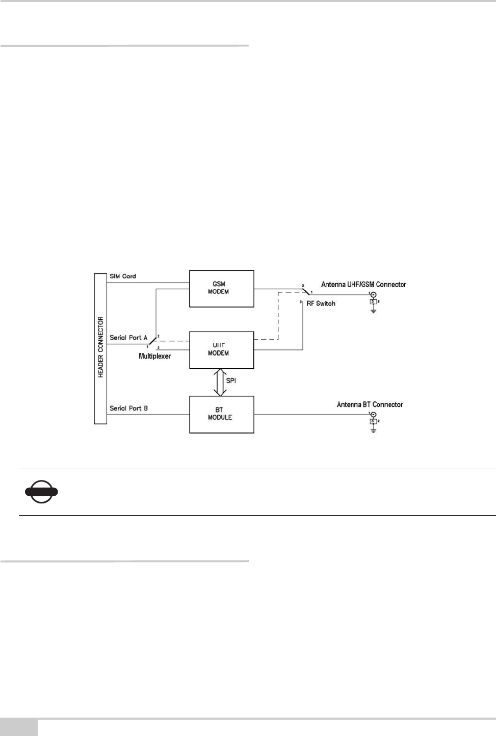
Hardware Architecture
Functional Requirements
The UHF Modem/Cell/BT Board consists of the following main sections:
• UHF modem Tx/Rx modem;
• GSM/GPRS, 3G, or CDMA modules;
• Bluetooth module.
The block diagram of the DUHFII is presented below. In the figure, consider GSM modem as referring
to either GSM/GPRS or CDMA modules.
Electromagnetic Compliance
This device complies with part 15 of the FCC Rules. Operation is subject to the condition that this
device does not cause harmful interference.
NOTICE
The GSM/GPRS (or CDMA) module installation is optional. The mechanical design and software tools
provide easy way for GSM/GPRS module optional installation and configuration.

Electromagnetic Compatibility
P/N 7010-xxxx 1-5
Changes or modifications not expressly approved by the manufacturer could void the user’s authority
to operate the equipment.
Installation of Digital UHF II module into device shall comply with section 2.1091 of the FCC Rules.
If not possible to ensure that the separation between the user and the UHF antenna is greater than 30
cm, the user manual shall contain a statement warning the user to stay away from the UHF antenna by
30 cm at least when the UHF radio is operating in transmit mode.
UHF and Bluetooth antennas shall be shielded from the Digital UHF II module by the construction of
the device, so that not to cause harmful interference to the module.
Electromagnetic Compatibility
Shielding Considerations
The DUHF II transceiver is designed to operate in proximity to noise generating circuitry. However,
certain radiated or conducted frequencies may degrade the performance of the DUHF II transceiver or
render it inoperable. When possible, provide well-grounded shielding between circuits that radiate,
such as power supplies, voltage-controlled oscillators, crystal oscillators and the DUHF II transceiver.
Frequency Planning
Radiated and conducted signals to and from the DUHF II transceiver may cause problems due to
interference. Proper attention to frequency planning may reduce interference from radiated or
conducted frequencies that fall within the pass-bands of the filters at the IF frequencies.
It is recommended the use of upfront analysis of the product frequency plan (including harmonics) and
then the use of a spectrum analyzer to determine the potential for interference within the pass-bands of
the various front-end and band pass filters.
WARNING
The DUHF II is classified as an intentional radiator of type radio transceiver. Conducted and
radiated emissions of the standard DUHF II transceiver do not exceed the requirements of FCC
part 90. OEM is responsible for full compliance of final product.
WARNING
Frequencies ranging from 403 to 413 MHz may adversely affect GPS L2.
Do not use these frequencies with a Topcon GNSS receiver.

Introduction
Digital UHF II EXTERNAL DESIGN SPECIFICATION
1-6
Mechanical Considerations
EMI interferers
The DUHF II transceiver is easily mounted inside new and existing products. The DUHF II transceiver
is specifically designed for operation in harsh environments. For best performance, mount the radio
away from potential EMI radiators and route RF signals apart from digital signals.
Shock and Vibration
Sensitive radio transceivers, such as the DUHF II transceiver, are susceptible to interference due to
mechanical shock and vibration. To reduce the potential for electromechanical interference, a
robust mounting scheme must be used when being integrated into other systems.
Thermal Transfer
The DUHF II transceiver requires additional thermal heat dissipation in order to supply maximum
power out at elevated ambient temperatures and high duty cycles. The DUHF II transceiver has a
thermal sensor and a firmware controlled limit switch. The DUHF II will shut down when the PCB
temperature reaches 100°C to prevent permanent damage to transmitter. The DUHF II will produce
approximately 6 Watts of heat at full RF power out.
Materials
The DUHF II transceiver is housed in a metal shield that is a conductor and is electrically connected to
the ground and signal ground pins.
WARNING
It is not recommend the bundling of the antenna interface cable with other signal cables internal
to your product.

P/N 7010-xxxx 2-1
Chapter 2
Command Reference
Introduction
This command reference describes in detail all the commands available in version 1.2a9 of the
DUHFII firmware running on the Digital UHFII modems from Topcon Positioning Systems Inc. This
reference provides a very limited amount of feature descriptions, explanations of the technologies, or
configuration examples. For detailed information about the various features and technologies
supported by DUHFII modems, see “Introduction” on page 1-1.
Intended Audience
This reference is intended for system engineers, system designers, and programmers who are
communicating with the DUHFII modems using the command interface, and are designing or
implementing applications that use the DUHFII commands.

Command Reference
Digital UHF II EXTERNAL DESIGN SPECIFICATION
2-2
Icons
This reference includes icons that appear in the left margin and are designed to help you clearly
identify operating mode in which you can apply a particular command. The following icons are used
throughout this reference:
Operating Modes
The DUHFII modem can be operated in ether of the following modes:
• Factory – This mode is intended for the factory floor only. In this mode, factory personnel can
calibrate the modem and upload the factory firmware image and bootloader to it. The modem
enters Factory mode initially and brings out of this mode after a normal country configuration file
is uploaded.
• Dealer – This mode is intended for the dealers. In this mode, a dealer can load a dealer
configuration file to the modem. This file contains a customized set of parameters that the dealer
have selected to run on the modem. For details about the parameters available in this file, see
“Configuration Files” on page 2-3. The modem enters Dealer mode after a country configuration
file and brings out of this mode after a normal dealer configuration file is uploaded. Once the
modem brings out of Dealer mode, it automatically goes into User mode.
• User – This mode is intended for the end-users. In this mode, a user can apply the parameters
available in the dealer configuration file to the modem. For details about the parameters available
in the dealer configuration file, see “Configuration Files” on page 2-3. Note that every DUHFII
modem shipped to an end-user must be in User mode.
Keys Operating Mode
Command applies in Factory mode
only.
Command applies in Dealer mode
only.
Command applies in User mode only.

Firmware Images
P/N 7010-xxxx 2-3
Firmware Images
The DUHFII modem stores two firmware images; a factory and a user image.
• The factory image is the factory-installed firmware that is permanently available on the DUHFII
modem.
• The user image is the user-installed firmware that normally controls all modem operations,
including its normal boot process. If the modem boot process with the user image fails for any
reason, the modem can be booted with the factory image.
Initially, the modem is initialized with factory and user firmware images which are identical.
Configuration Files
The DUHFII modem stores three configuration files, specifically: factory configuration file, dealer
configuration file, and country configuration file.
Factory configuration file
This file stores modem calibration parameters and is generated only by the test bench on the factory
floor.
Dealer configuration file
The dealer configuration file limits the selection of frequencies, channel spacings and maximum
output power for an end user. Note that the allowed frequencies are defined by a list of specified
frequencies, not by the range.
typedef struct
{
unsigned int freq; // Hz
short reserved; // = 0
char spacing; // 0 - 25kHz, 1 - 12.5 kHz, 2 - 20 kHz
char max_power; // dBm
} t_U_Channels;
typedef union

Command Reference
Digital UHF II EXTERNAL DESIGN SPECIFICATION
2-4
Country configuration file
The country configuration file limits the range of allowed frequencies depending on the allocation of
RF bands in a specific country (region). It allows up to four contingent frequency ranges, each with its
own maximum output power and channel spacings.
{
t_U_Channels chan;
unsigned int crc32;
} t_User_Channels;
typedef struct
{
unsigned int DCFG; // 0x47464344 = DCFG signature
unsigned short version; // = 0
unsigned short number_of_channels; // 0-64 variable size structure
char callsign[32]; // zero terminated string
t_User_Channels item[64];
unsigned int crc32; // The CRC32 is a standard CRC with a
// polynomial of 0x04C11DB7, an initial
// value of 0xFFFFFFFF and an inverted
// output. The same algorithm is used in
// ZIP and RAR archives as well as in the
// ITU V.42 standard.
} t_DealerConfig;
typedef struct
{
unsigned int start_freq; // Hz, 0 if unused
unsigned int stop_freq; // Hz, 0 if unused
unsigned int spacing_enable_mask; // 0x00000001 - 25kHz,
// 0x00000002 - 12.5kHz,
// 0x00000004 - 20kHz
short reserved1; // = 0
char reserved2; // = 0
char max_power; // dBm, 10-30
} t_Freq_Ranges;
typedef struct
{
unsigned int CCFG; // 0x47464344 = CCFG signature
unsigned short version; // = 0, incompatible modifications will have
// different number
unsigned short reserved; // = 0
t_Freq_Ranges band[4]; // fixed size, not used ranges should be
// zero

Commands
P/N 7010-xxxx 2-5
Commands
This section lists the commands and subcommands supported by the DUHFII modem.
DATAMODE
++++
unsigned int crc32; // The CRC32 is a standard CRC with a
// polynomial of 0x04C11DB7, an initial
// value of 0xFFFFFFFF and an inverted
// output. The same algorithm is used in
// ZIP and RAR archives as well as in the
// ITU V.42 standard.
} t_CountryConfig;
Description: Switches the modem to data mode.
Access: write-only
Subcommands: This command has no subcommands.
Usage
Guidelines:
If the modem does not receive a command within 60
seconds, it will enter data mode.
When the modem generates test signals (TSTSGL
1...TSTSGL 6), the modem will remain in command
mode until you disable the test signals with the
command TSTSGL 0.
Command
Examples: DATAMODE
History: This command was introduced in the first release of
firmware.
Description: Switches the modem to command mode.
Access: write-only
Subcommands: This command has no subcommands.
Usage
Guidelines:
The guard time is 20 ms.
You can also enter command mode by asserting a DTR
line. To switch back to data mode, you must deassert the
DTR line. A 60-seconds timeout is disabled while the
DTR line is asserted.

Command Reference
Digital UHF II EXTERNAL DESIGN SPECIFICATION
2-6
LINK
LINK Subcommands:
MAP
RFSW
Command
Examples: ++++
History: This command was introduced in the first release of
firmware.
Description: Reports the current configuration of the RF data link.
Access: read-only
Subcommands: MAP, RFSW, MOD, PROT, PWRB, PWRW, SPACE,
CHAN, UCHAN, FREQ, SCRAM, FEC
Usage
Guidelines: This command has no usage guidelines.
Command
Examples:
LINK
LINK SPACE 0
History: This command was introduced in the first release of
firmware.
Description: Reports the channel map from the dealer list.
Access: read-only
Usage
Guidelines: This subcommand has no usage guidelines.
Command
Examples: LINK MAP
History: This subcommand was introduced in the first release of
firmware.
Description: Specifies the datalink type being used by the modem.
Access: read & write
Values: 0 – UHF
1 – GSM/GPRS
Usage
Guidelines: This subcommand has no usage guidelines.
Description: Switches the modem to command mode.
Access: write-only

Commands
P/N 7010-xxxx 2-7
MOD
PROT
Command
Examples:
LINK RFSW
LINK RFSW 1
History: This subcommand was introduced in the first release of
firmware.
Description: Specifies the modulation type being used by the modem.
Access: read & write
Values: 5 – GMSK
6 – 4LFSK
Usage
Guidelines: This subcommand has no usage guidelines.
Command
Examples:
LINK MOD
LINK MOD 6
History: This subcommand was introduced in the first release of
firmware.
Description: Specifies the radio protocol and whether the modem is
configured to transmit or receive data.
Access: read & write
Values:
7 – Trimble RX
8 – Trimble TX
11 – Trimble Repeater
12 – PDL RX
13 – PDL TX
14 – PDL RTR
15 – Satel RX
16 – Satel TX
17 – Satel Repeater
18 – Satel FCS On RX
19 – Satel FCS On TX
20 – Satel FCS On Repeater
Usage
Guidelines: This subcommand has no usage guidelines.
Command
Examples:
LINK PROT
LINK PROT 16
History: This subcommand was introduced in the first release of
firmware.
Description: Specifies the datalink type being used by the modem.
Access: read & write
Values: 0 – UHF
1 – GSM/GPRS

Command Reference
Digital UHF II EXTERNAL DESIGN SPECIFICATION
2-8
LINK Subcommands (Continued):
PWRB
PWRW
Description: Specifies the output power in dBm.
Access: read & write
Values: [10...30]
Usage
Guidelines:
The restrictions from the country and/or dealer
configuration files may apply.
Although you may specify any output power within its
range of allowed values, only the following values are
factory-calibrated and thus recommended for use:10, 13,
17, 20, 23, 27, 30.
Command
Examples:
LINK PWRB
LINK PWRB 20
History: This subcommand was introduced in the first release of
firmware.
Description: Specifies the output power in mW.
Access: read & write
Values: [10...1000]
Usage
Guidelines:
Reading will return a value rounded to the nearest integer
value in mW.
The restrictions from the country and/or dealer
configuration files may apply.
Although you may specify any output power within its
range of allowed values, only the following values are
factory-calibrated and thus recommended for use: 10, 20,
50, 100, 200, 500, 1000.
Command
Examples:
LINK PWRW
LINK PWRW 500
History: This subcommand was introduced in the first release of
firmware.

Commands
P/N 7010-xxxx 2-9
LINK Subcommands (Continued):
SPACE
CHAN
UCHAN
Description: Specifies the channel spacing in kHz.
Access: read & write
Values:
0 – 25 kHz
1 – 12.5 kHz
2 – 20 kHz
Usage
Guidelines:
The restrictions from the country and/or dealer
configuration files may apply.
Command
Examples:
LINK SPACE
LINK SPACE 1
History: This subcommand was introduced in the first release of
firmware.
Description: Specifies the frequency channel.
Access: read & write
Values: [1...9601]
Usage
Guidelines:
For 25 and 12.5 kHz spacings, the following formula is used to
relate the frequency and its frequency channel:
FRQ=410000000+(n-1)*6250, where n is the frequency channel.
For 20 kHz spacing, the following formula is used to relate the
frequency and its frequency channel: FRQ=410000000+(n-
10001)*5000, where n is the frequency channel.
The restrictions from the country and/or dealer configuration files
may apply.
Command
Examples:
LINK CHAN
LINK CHAN 1
History: This subcommand was introduced in the first release of firmware.
Description: Selects channel settings from the dealer list.
Access: read & write
Values: [0...63]
Usage
Guidelines: This subcommand has no usage guidelines.
Command
Examples:
LINK UCHAN
LINK UCHAN 12
History: This subcommand was introduced in the first release of firmware.
Command Reference
Digital UHF II EXTERNAL DESIGN SPECIFICATION
2-10
LINK Subcommands (Continued):
FREQ
SCRAM
FEC
Description: Specifies the channel frequency.
Access: read & write
Values: [390000000...480000000]
Usage
Guidelines:
The frequency will be rounded to the nearest available channel
depending on channel spacing. An actual frequency range will be
defined by Country Configuration.
The restrictions from the country and/or dealer configuration files
may apply.
Command
Examples:
LINK FREQ
LINK FREQ 420000000
History: This subcommand was introduced in the first release of firmware.
Description: Configures scrambling.
Access: read & write
Values:
[0...255]
0 – disabled
[1...255] – scrambling enabled
Usage
Guidelines:
Scrambling is always enabled for TrimTalk.
Scrambling is always disabled for Satel.
Command
Examples:
LINK SCRAM
LINK SCRAM 1
History: This subcommand was introduced in the first release of firmware.
Description: Configures forward error correction.
Access: read & write
Values: 0 – disabled
1 – enabled
Usage
Guidelines:
FEC is supported for PDL and Satel.
FEC is always disabled for TrimTalk.
Command
Examples:
LINK FEC
LINK FEC 1
History: This subcommand was introduced in the first release of firmware.

Commands
P/N 7010-xxxx 2-11
LINK Subcommands (Continued):
ATI
ATI Subcommands:
ID
SN
Description: Displays the firmware and hardware details.
Access: read-only
Subcommands: ID, SN, HW, SW, BL
Usage
Guidelines: This command has no usage guidelines.
Command
Examples: ATI
History: This command was introduced in the first release of
firmware.
Description: Displays the product ID.
Access: read-only
Usage
Guidelines: This subcommand has no usage guidelines.
Command
Examples: ATI ID
History: This subcommand was introduced in the first release of
firmware.
Description: Displays the serial number.
Access: read-only
Usage
Guidelines: This subcommand has no usage guidelines.
Command
Examples: ATI SN
History: This subcommand was introduced in the first release of
firmware.

Command Reference
Digital UHF II EXTERNAL DESIGN SPECIFICATION
2-12
ATI Subcommands (Continued):
HW
SW
BL
Description: Displays the hardware revision.
Access: read-only
Usage
Guidelines: This subcommand has no usage guidelines.
Command
Examples: ATI HW
History: This subcommand was introduced in the first release of
firmware.
Description: Displays the software revision.
Access: read-only
Usage
Guidelines: This subcommand has no usage guidelines.
Command
Examples: ATI SW
History: This subcommand was introduced in the first release of
firmware.
Description: Displays the bootloader version.
Access: read-only
Usage
Guidelines: This subcommand has no usage guidelines.
Command
Examples: ATI BL
History: This subcommand was introduced in the first release of
firmware.

Commands
P/N 7010-xxxx 2-13
ATI Subcommands (Continued):
STATE
STATE Subcommands:
RSSI
BER
Description: Displays the current state.
Access: read-only
Subcommands: RSSI, BER, FREQ, CHAN, UCHAN, TEMP, MODE,
BAND, PWRB
Usage
Guidelines: This command has no usage guidelines.
Command
Examples: STATE
History: This command was introduced in the first release of
firmware.
Description: Displays the RSSI level.
Access: read-only
Usage
Guidelines: This subcommand has no usage guidelines.
Command
Examples: STATE RSSI
History: This subcommand was introduced in the first release of
firmware.
Description: Displays the bit error rate.
Access: read-only
Usage
Guidelines: This subcommand has no usage guidelines.
Command
Examples: STATE BER
History: This subcommand was introduced in the first release of
firmware.

Command Reference
Digital UHF II EXTERNAL DESIGN SPECIFICATION
2-14
STATE Subcommands (Continued):
FREQ
CHAN
UCHAN
Description: Displays the frequency.
Access: read-only
Usage
Guidelines: This subcommand has no usage guidelines.
Command
Examples: STATE FREQ
History: This subcommand was introduced in the first release of
firmware.
Description: Displays the channel number.
Access: read-only
Usage
Guidelines: This subcommand has no usage guidelines.
Command
Examples: STATE CHAN
History: This subcommand was introduced in the first release of
firmware.
Description: Displays the user-selected channel number.
Access: read-only
Usage
Guidelines: This subcommand has no usage guidelines.
Command
Examples: STATE UCHAN
History: This subcommand was introduced in the first release of
firmware.

Commands
P/N 7010-xxxx 2-15
STATE Subcommands (Continued):
TEMP
MODE
BAND
Description: Displays the modem temperature.
Access: read-only
Usage
Guidelines: This subcommand has no usage guidelines.
Command
Examples: STATE TEMP
History: This subcommand was introduced in the first release of
firmware.
Description: Displays the current operating mode.
Access: read-only
Values:
1 – Factory mode
2 – Dealer mode
3 – User mode
Usage
Guidelines: This subcommand has no usage guidelines.
Command
Examples: STATE MODE
History: This subcommand was introduced in the first release of
firmware.
Description: Displays the current frequency and spacing limits.
Access: read-only
Usage
Guidelines: This subcommand has no usage guidelines.
Command
Examples: STATE BAND
History: This subcommand was introduced in the first release of
firmware.

Command Reference
Digital UHF II EXTERNAL DESIGN SPECIFICATION
2-16
STATE Subcommands (Continued):
PWRB
@ECHO
DPORT
Description: Displays the output power.
Access: read-only
Usage
Guidelines: This subcommand has no usage guidelines.
Command
Examples: STATE PWRB
History: This subcommand was introduced in the first release of
firmware.
Description: Configures echo for command mode.
Access: read & write
Values: ON – Echo on
OFF – Echo off
Subcommands: This command has no subcommands.
Usage
Guidelines: This command has no usage guidelines.
Command
Examples: @ECHO ON
History: This command was introduced in the first release of
firmware.
Description: Displays parameters for the serial port in Data mode.
Access: read-only
Subcommands: RATE, BITS, PARITY, FLOW, STOP
Usage
Guidelines: This command has no usage guidelines.
Command
Examples: DPORT
History: This command was introduced in the first release of
firmware.

Commands
P/N 7010-xxxx 2-17
DPORT Subcommands:
RATE
BITS
Description: Configures the baud rate.
Access: read & write
Values:
0 – equals MPORT RATE
1 – 1200
2 – 2400
3 – 4800
4 – 9600
5 – 14400
6 – 19200
7 – 38400
8 – 57600
9 – 115200
Usage
Guidelines: This subcommand has no usage guidelines.
Command
Examples: DPORT RATE 7
History: This subcommand was introduced in the first release of
firmware.
Description: Configures the number of data bits.
Access: read & write
Values: 7, 8
Usage
Guidelines: This subcommand has no usage guidelines.
Command
Examples: DPORT BITS 7
History: This subcommand was introduced in the first release of
firmware.

Command Reference
Digital UHF II EXTERNAL DESIGN SPECIFICATION
2-18
DPORT Subcommands (Continued):
PARITY
FLOW
STOP
Description: Configures the parity.
Access: read & write
Values:
0 – none
1 – odd
2 – even
Usage
Guidelines: This subcommand has no usage guidelines.
Command
Examples: DPORT PARITY 1
History: This subcommand was introduced in the first release of
firmware.
Description: Configures the handshaking.
Access: read & write
Values:
0 – none
1 – unused
2 – RTS/CTS
Usage
Guidelines: This subcommand has no usage guidelines.
Command
Examples: DPORT FLOW 2
History: This subcommand was introduced in the first release of
firmware.
Description: Configures the number of stop bits.
Access: read & write
Values: 1 – 1 stop bit
2 – 2 stop bits
Usage
Guidelines: This subcommand has no usage guidelines.
Command
Examples: DPORT STOP 1
History: This subcommand was introduced in the first release of
firmware.

Commands
P/N 7010-xxxx 2-19
DPORT Subcommands (Continued):
MPORT
MPORT Subcommands:
RATE
Description: Displays parameters for the serial port in Maintenance
(command) mode.
Access: read-only
Subcommands: RATE, BITS, PARITY, FLOW, STOP
Usage
Guidelines: This command has no usage guidelines.
Command
Examples: DPORT
History: This command was introduced in the first release of
firmware.
Description: Configures the baud rate.
Access: read & write
Values:
0 – equals MPORT RATE
1 – 1200
2 – 2400
3 – 4800
4 – 9600
5 – 14400
6 – 19200
7 – 38400
8 – 57600
9 – 115200
Usage
Guidelines: This subcommand has no usage guidelines.
Command
Examples: MPORT RATE 7
History: This subcommand was introduced in the first release of
firmware.

Command Reference
Digital UHF II EXTERNAL DESIGN SPECIFICATION
2-20
MPORT Subcommands (Continued):
BITS
PARITY
FLOW
Description: Configures the number of data bits.
Access: read & write
Values: 7, 8
Usage
Guidelines: This subcommand has no usage guidelines.
Command
Examples: MPORT BITS 7
History: This subcommand was introduced in the first release of
firmware.
Description: Configures the parity.
Access: read & write
Values:
0 – none
1 – odd
2 – even
Usage
Guidelines: This subcommand has no usage guidelines.
Command
Examples: MPORT PARITY 1
History: This subcommand was introduced in the first release of
firmware.
Description: Configures the handshaking.
Access: read & write
Values:
0 – none
1 – unused
2 – RTS/CTS
Usage
Guidelines: This subcommand has no usage guidelines.
Command
Examples: MPORT FLOW 2
History: This subcommand was introduced in the first release of
firmware.

Commands
P/N 7010-xxxx 2-21
MPORT Subcommands (Continued):
STOP
SAVE
RESTORE
Description: Configures the number of stop bits.
Access: read & write
Values: 1 – 1 stop bit
2 – 2 stop bits
Usage
Guidelines: This subcommand has no usage guidelines.
Command
Examples: MPORT STOP 1
History: This subcommand was introduced in the first release of
firmware.
Description: Stores the current settings to Flash memory.
Access: write-only
Subcommands: This command has no subcommands.
Usage
Guidelines: This command has no usage guidelines.
Command
Examples: SAVE
History: This command was introduced in the first release of
firmware.
Description: Restores the default settings.
Access: write-only
Subcommands: This command has no subcommands.
Usage
Guidelines: This command has no usage guidelines.
Command
Examples: RESTORE
History: This command was introduced in the first release of
firmware.

Command Reference
Digital UHF II EXTERNAL DESIGN SPECIFICATION
2-22
PROTIME
TCXO
ALC
Description: Configures the protocol timeout.
Access: read & write
Values: [10...255]
Subcommands: This command has no subcommands.
Usage
Guidelines: This command has no usage guidelines.
Command
Examples: PROTIME 15
History: This command was introduced in the first release of
firmware.
Description: Adjusts oscillator offset.
Access: read & write
Values: [0...32]
Subcommands: This command has no subcommands.
Usage
Guidelines: This command has no usage guidelines.
Command
Examples: TCXO 20
History: This command was introduced in the first release of
firmware.
Description: Configures transmitter gains.
Access: read-only
Subcommands: A, B, D, X, Y
Usage
Guidelines: This command has no usage guidelines.
Command
Examples: ALC
History: This command was introduced in the first release of
firmware.

Commands
P/N 7010-xxxx 2-23
ALC Subcommands:
A
B
D
Description: Configures the pre-amplifier gain.
Access: read & write
Values: [0...31]
Usage
Guidelines: This subcommand has no usage guidelines.
Command
Examples:
ALC A
ALC A 12
History: This subcommand was introduced in the first release of
firmware.
Description: Configures the amplifier gain.
Access: read & write
Values: [0...32]
Usage
Guidelines: This subcommand has no usage guidelines.
Command
Examples:
ALC B
ALC B 10
History: This subcommand was introduced in the first release of
firmware.
Description: Configures the DAC gain.
Access: read & write
Values: [0...32767]
Usage
Guidelines: This subcommand has no usage guidelines.
Command
Examples:
ALC D
ALC D 15343
History: This subcommand was introduced in the first release of
firmware.

Command Reference
Digital UHF II EXTERNAL DESIGN SPECIFICATION
2-24
ALC Subcommands (Continued):
X
Y
CSAVE
Description: Configures the TX modulator offset.
Access: read & write
Values: [-4096...4095]
Usage
Guidelines: This subcommand has no usage guidelines.
Command
Examples:
ALC X
ALC X -4090
History: This subcommand was introduced in the first release of
firmware.
Description: Configures the TX modulator offset.
Access: read & write
Values: [-4096...4095]
Usage
Guidelines: This subcommand has no usage guidelines.
Command
Examples:
ALC Y
ALC Y 4090
History: This subcommand was introduced in the first release of
firmware.
Description: Stores the current ALC values to the calibration table.
Access: write-only
Subcommands: This command has no subcommands.
Usage
Guidelines: Used for manual calibration.
Command
Examples: CSAVE
History: This command was introduced in the first release of
firmware.

Commands
P/N 7010-xxxx 2-25
TSTSGL
FCS
FCS Subcommands:
CHANCLR
Description: Configures test signals.
Access: write-only
Values: [0...6]
Subcommands: This command has no subcommands.
Usage
Guidelines: This command has no usage guidelines.
Command
Examples: TSTSGL 3
History: This command was introduced in the first release of
firmware.
Description: Configures the protocol timeout.
Access: read-only
Subcommands: CHANCLR, NETID, RXLT, BI, BDT, CHANON,
CHANOFF, RSSI
Usage
Guidelines: This command applies to Satel protocol only.
Command
Examples: FCS
History: This command was introduced in the first release of
firmware.
Description: Clears the channel list.
Access: write-only
Usage
Guidelines: This subcommand has no usage guidelines.
Command
Examples: FCS CHANCLR
History: This subcommand was introduced in the first release of
firmware.

Command Reference
Digital UHF II EXTERNAL DESIGN SPECIFICATION
2-26
FCS Subcommands (Continued):
NETID
RXLT
BI
Description: Configures network ID.
Access: read & write
Values: [0x0000...0xFFFF]
Usage
Guidelines: This subcommand has no usage guidelines.
Command
Examples: FCS NETID 0x0000
History: This subcommand was introduced in the first release of
firmware.
Description: Configures the RX listen timeout.
Access: read & write
Values: [0...65535]
Usage
Guidelines: This subcommand has no usage guidelines.
Command
Examples: FCS RXLT 30
History: This subcommand was introduced in the first release of
firmware.
Description: Configures the beacon interval.
Access: read & write
Values: [0...65535]
Usage
Guidelines: This subcommand has no usage guidelines.
Command
Examples: FCS BI 50
History: This subcommand was introduced in the first release of
firmware.

Commands
P/N 7010-xxxx 2-27
FCS Subcommands (Continued):
BDT
CHANON
CHANOFF
Description: Configures the beacon disable timeout.
Access: read & write
Values: [0...65535]
Usage
Guidelines: This subcommand has no usage guidelines.
Command
Examples: FCS BDT 60
History: This subcommand was introduced in the first release of
firmware.
Description: Enables FCS for the selected channel.
Access: write-only
Values: [0...47]
Usage
Guidelines: This subcommand has no usage guidelines.
Command
Examples: FCS CHANON 9
History: This subcommand was introduced in the first release of
firmware.
Description: Disables FCS for the selected channel.
Access: write-only
Values: [0...47]
Usage
Guidelines: This subcommand has no usage guidelines.
Command
Examples: FCS CHANOFF 9
History: This subcommand was introduced in the first release of
firmware.

Command Reference
Digital UHF II EXTERNAL DESIGN SPECIFICATION
2-28
FCS Subcommands (Continued):
RSSI
ADDR
ADDR Subcommands:
TXEN
Description: Configures the RSSI threshold.
Access: read & write
Values: [80...118]
Usage
Guidelines: This subcommand has no usage guidelines.
Command
Examples: FCS RSSI 95
History: This subcommand was introduced in the first release of
firmware.
Description: Displays Satel protocol routing.
Access: read-only
Subcommands: TXEN, RXEN, TXAUTO, RX2RS, TXP, RXP, TXS,
RXS
Usage
Guidelines: This command applies to Satel protocol only.
Command
Examples: ADDR
History: This command was introduced in the first release of
firmware.
Description: Configures address transmission.
Access: write-only
Values: 1, 0
Usage
Guidelines: This subcommand has no usage guidelines.
Command
Examples: ADDR TXEN 1
History: This subcommand was introduced in the first release of
firmware.

Commands
P/N 7010-xxxx 2-29
ADDR Subcommands (Continued):
RXEN
TXAUTO
RX2RS
Description: Configures address receiving.
Access: write-only
Values: 1, 0
Usage
Guidelines: This subcommand has no usage guidelines.
Command
Examples: ADDR RXEN 1
History: This subcommand was introduced in the first release of
firmware.
Description: Configures transmission address auto switch.
Access: write-only
Values: 1, 0
Usage
Guidelines: This subcommand has no usage guidelines.
Command
Examples: ADDR TXAUTO 1
History: This subcommand was introduced in the first release of
firmware.
Description: Configures received address to RS port.
Access: write-only
Values: 1, 0
Usage
Guidelines: This subcommand has no usage guidelines.
Command
Examples: ADDR RX2RS 1
History: This subcommand was introduced in the first release of
firmware.

Command Reference
Digital UHF II EXTERNAL DESIGN SPECIFICATION
2-30
ADDR Subcommands (Continued):
TXP
RXP
TXS
Description: Configures the transmission primary address.
Access: read & write
Values: [0x0000...0xFFFF]
Usage
Guidelines: This subcommand has no usage guidelines.
Command
Examples: ADDR TXP 0x0000
History: This subcommand was introduced in the first release of
firmware.
Description: Configures the receiving primary address.
Access: read & write
Values: [0x0000...0xFFFF]
Usage
Guidelines: This subcommand has no usage guidelines.
Command
Examples: ADDR RXP 0x0000
History: This subcommand was introduced in the first release of
firmware.
Description: Configures the transmission secondary address.
Access: read & write
Values: [0x0000...0xFFFF]
Usage
Guidelines: This subcommand has no usage guidelines.
Command
Examples: ADDR TXS 0x0001
History: This subcommand was introduced in the first release of
firmware.

Commands
P/N 7010-xxxx 2-31
ADDR Subcommands (Continued):
RXS
TXDELAY
HELP
Description: Configures the receiving secondary address.
Access: read & write
Values: [0x0000...0xFFFF]
Usage
Guidelines: This subcommand has no usage guidelines.
Command
Examples: ADDR RXS 0x0002
History: This subcommand was introduced in the first release of
firmware.
Description: Configures transmit delay.
Access: read & write
Values: [0...65535]
Subcommands: This command has no subcommands.
Usage
Guidelines: This command has no usage guidelines.
Command
Examples: TXDELAY 20
History: This command was introduced in the first release of
firmware.
Description: Displays commands and their description.
Access: read-only
Subcommands: This command has no subcommands.
Usage
Guidelines: This command has no usage guidelines.
Command
Examples: HELP
History: This command was introduced in the first release of
firmware.

Command Reference
Digital UHF II EXTERNAL DESIGN SPECIFICATION
2-32
XMOD
XMOD Subcommands:
IMAGE
FACTIMAGE
Description: Uploads firmware and configuration files to the modem
using the X-Modem protocol.
Access: read-only
Subcommands: IMAGE, FACTIMAGE, LOADER, DDFG, DCCFG,
DFCFG
Usage
Guidelines:
To start uploading, you need to supply this command
with the corresponding subcommand.
Command
Examples: XMOD
History: This command was introduced in the first release of
firmware.
Description: Uploads user firmware.
Access: write-only
Usage
Guidelines: This subcommand has no usage guidelines.
Command
Examples: XMOD IMAGE
History: This subcommand was introduced in the first release of
firmware.
Description: Uploads factory firmware.
Access: write-only
Usage
Guidelines: This subcommand has no usage guidelines.
Command
Examples: XMOD FACTIMAGE
History: This subcommand was introduced in the first release of
firmware.

Commands
P/N 7010-xxxx 2-33
XMOD Subcommands (Continued):
DDCFG
DCCFG
DFCFG
BOOT
Description: Uploads dealer configuration in TPS format.
Access: write-only
Usage
Guidelines:
Successful loading will switch the modem from dealer to
user mode.
Command
Examples: XMOD DDCFG
History: This subcommand was introduced in the first release of
firmware.
Description: Uploads country configuration.
Access: write-only
Usage
Guidelines:
Successful loading will switch the modem from factory to
dealer mode.
Command
Examples: XMOD DCCFG
History: This subcommand was introduced in the first release of
firmware.
Description: Uploads factory calibration settings.
Access: write-only
Usage
Guidelines: This subcommand has no usage guidelines.
Command
Examples: XMOD DFCFG
History: This subcommand was introduced in the first release of
firmware.
Description: Reboots the modem.
Access: write-only
Subcommands: IMAGE, CFG
Usage
Guidelines: This command has no usage guidelines.

Command Reference
Digital UHF II EXTERNAL DESIGN SPECIFICATION
2-34
BOOT Subcommands:
IMAGE
CFG
Command
Examples: BOOT
History: This command was introduced in the first release of
firmware.
Description: Reboots the modem and selects a copy of firmware.
Access: write-only
Values: 0 – Factory firmware
1 – User firmware
Usage
Guidelines: This subcommand has no usage guidelines.
Command
Examples: BOOT IMAGE 1
History: This subcommand was introduced in the first release of
firmware.
Description: Reboots the modem and selects a configuration.
Access: write-only
Values: 0 – Factory configuration
1 – User configuration
Usage
Guidelines: This subcommand has no usage guidelines.
Command
Examples: BOOT CFG 1
History: This subcommand was introduced in the first release of
firmware.
Description: Reboots the modem.
Access: write-only
P/N 7010-xxxx 3-1
Chapter 3
Specifications
Board Specifications
General
Radio interfaces UHF 400 – 470 MHz
Bluetooth (optional)
GSM/GPRS 850/900/1800/1900 (optional)
CDMA 1xRTT 800/1900 (optional)
HSPA 850/900/1700/1900/2100 (optional)
Simultaneous operation Bluetooth / UHF - yes
Bluetooth / GSM (CDMA, HSPA) – yes
UHF / GSM (CDMA, HSPA) - no
Bluetooth TAYUO YUDEN EYSF3CAVX
2.0+EDR
GSM/GPRS Motorola G24
CDMA Motorola C24
HSPA Motorola H24

Specifications
Digital UHF II EXTERNAL DESIGN SPECIFICATION
3-2
Compliance FCC 47CFR PT 15.247
FCC 47CFR PT 90
IC RSS 119
ETSI EN 300-113-2 V1.6.1 (in enclosure only)
EN 300 328 (in enclosure only)
ETSI EN 301 489-1 V1.9.2
ETSI EN 301 489-5 V1.3.1
ETSI EN 301 489-17 V2.1.1
Interface
Antenna connector UHF/GSM/
CDMA/HSPA
MMCX, Molex 73415-1001 or similar
Antenna connector Bluetooth RADIALL R107 003 010
Interface RS-232
Data Speed of Interface 300 to 115200 bps
Interface Connector 2x26 (pinout see below)
Operating Voltage 6-14 Vdc
UHF Transceiver
Operating Frequency Range 400 – 470 MHz
Modulation Technique GMSK, 4FSK
Protocol Satel (without FCS)
Configuration Programmable to limit operation to given frequency range or list of channels, given channel
spacing, given output power, RX mode
Max. Distance Range 15 miles/24 km
Occupied Bandwidth (Channel
Spacing)
25 kHz, 20 kHz or 12.5 kHz (user selectable)
Data Rate (@25 kHz Channel
Spacing)
9600 bps –GMSK
19200 bps –4FSK
Data Rate (@20 kHz Channel
Spacing)
4800 bps –GMSK
9600 bps –4FSK
Data Rate (@12.5 kHz Channel
Spacing)
4800 bps –GMSK
9600 bps –4FSK
System Gain (Antenna gain is not
included):
GMSK
4FSK
149 dB (for 25 kHz Channel Spacing)
152 dB (for 12.5 kHz Channel Spacing)
147 dB (for 25 kHz Channel Spacing)
150 dB (for 12.5 kHz Channel Spacing
Roaming Speed 60 mph/96 km/h
End to End delay 60 ms
Power Consumption at 6 V 8.4 V 12 V
Max power consumption in RX
mode, W 1.8 1.9 2.3

Board Specifications
P/N 7010-xxxx 3-3
Max power consumption in TX
mode with 1W output, W 6.5 6.5 7.0
Max current in RX mode, A 0.3 0.23 0.17
Max current in TX mode, A 1.1 0.78 0.5
Compliance FCC Part 90
IC RSS 119
ETSI EN 300-113-2 V1.6.1
ETSI EN 301 489-1 V1.9.2
ETSI EN 301 489-5 V1.3.1
ETSI EN 301 489-17 V2.1.1
UHF Transmitter
Output Power 10, 13, 17, 20, 27, 30 dBm (user selectable)
Output Power Control Accuracy ±1.5 dB (at normal test conditions)
+2.0 dB and -3.0 dB (under extreme test conditions)
Nominal Output Impedance 50 Ohm
VSWR 2.0:1
Carrier Frequency Stability ±1.5 ppm initial stability over temp with ±3 ppm aging/year
Max. Frequency Error ±1.5 kHz (at normal test conditions)
±2.5 kHz (under extreme test conditions)
Adjacent Channel Power Below -37 dBm
Spurious Emission (Conducted and
Radiated)
frequency range 9 kHz – 1 GHz
frequency range 1 GHz – 12.75 GHz
Below -36 dBm
Below -30 dBm
Type of Emission F1D
FCC Part 90
§90.210(c) for 25 kHz Channel Spacing
§90.210(d) for 12.5 kHz Channel Spacing
ETSI EN 300-113-1 V1.5.1
Clause 5.1.4
Clause 8.6.1
UHF Receiver
Nominal Input Impedance 50 Ohm
Receiver Sensitivity for GMSK
(@ BER <1x 10⁻⁴, over temperature
-30oC to +60oC)
-119 dBm for 25 kHz Channel Spacing
-122 dBm for 12.5 kHz Channel Spacing
Receiver Sensitivity for 4FSK
(@ BER <1x 10⁻⁴, over temperature
-30oC to +60oC)
-117 dBm for 25 kHz Channel Spacing
-118 dBm for 20 kHz Channel Spacing
-120 dBm for 12.5 kHz Channel Spacing
Dynamic Range -119 to -1 dBm for GMSK
-117 to -1 dBm for 4FSK
Max. Input Signal Level -1 dBm
Specifications
Digital UHF II EXTERNAL DESIGN SPECIFICATION
3-4
Interface Connector
The main interface connector is a 56-pin header connector of FX5 series, HIROSE FX5-52P-SH (71).
Spurious Emission (Conducted and
Radiated)
frequency range 9 kHz – 1 GHz
frequency range 1 GHz – 12.75 GHz
Below -57 dBm
Below -47 dBm
Environmental
Temperature: FCC/ETSI compliant
operation range
-25 to +55 ºC
Temperature: operation range -30 to +60 ºC
Temperature: storage -40 to +85 ºC
Pin Name In/Out Level Description
A1 GND - GND
A2 GND - GND
A3 POWER_IN In +6...14 Vdc Power Supply
A4 POWER_IN In +6...14 Vdc Power Supply
A5 SPI_CSB In TTL SPI Chip Select (Active Low, Not Connected)
A6 SPI_MISO Out TTL Data from Bluetooth to Host (Not Connected)
A7 SPI_CLK In TTL CLOCK from Host to Bluetooth (Not Connected)
A8 RED Out HighZ/+3.3Vdc RXA LED Anode
A9 GRN Out HighZ/+3.3Vdc TXA LED Anode
A11 RTSA Out TTL Asserted by Radio Modem Clear To Send (CTS) data flow
control signal wired to RTS input on Topcon Receiver (Serial
Port A):
• 0VDC = Modem’s Transmit buffer not full, continue data
transferring
• 3.3VDC = Modem’s Transmit buffer full, stop data
transferring
A12 CTSA In TTL Asserted by Topcon Receiver data flow control signal to
Request To Send (RTS) data over Serial Port A:
• 0VDC = Receive Data from Modem is enabled
• 3.3VDC = Receive Data from Modem is disabled

Interface Connector
P/N 7010-xxxx 3-5
A13 RTSB Out TTL Asserted by Bluetooth transceiver Clear To Send (CTS) data
flow control signal wired to RTS input on Topcon Receiver
(Serial Port B):
• 0VDC = Bluetooth Transmit buffer not full, continue
transmitting
• 3.3VDC = Bluetooth Transmit buffer full, stop data
transferring
A14 CTSB In TTL Asserted by Topcon Receiver data flow control signal to
Request To Send (RTS) data over Serial Port B:
• 0VDC = Receive Data from Bluetooth is enabled
• 3.3VDC = Receive Data from Bluetooth is disabled
A15 GND - GND
A18 SIMRST Out Logic SIM Reset active LOW
A19 SIMCLK Out Logic SIM Clock
A20 SIMPRES In Logic SIM Presence active LOW
A22 PWR_ON In 0...+3.3 Vdc Radio modem ON/OFF control
• 0VDC = OFF
• 3.3VDC = ON
A23 POWER_IN In +6...14 Vdc Power Supply
A24 POWER_IN In +6...14 Vdc Power Supply
A25 GND - GND
A26 GND - GND
B1 GND - GND
B2 GND - GND
B3 POWER_IN In +6...14 Vdc Power Supply
B4 POWER_IN In +6...14 Vdc Power Supply
B5 SPI_MOSI In TTL Data from Host to Bluetooth (Not Connected)
B6 RESET_BT In TTL Reset of Bluetooth module (Active High, Not Connected)
B8 BLUE Out HighZ/+3.3Vdc Bluetooth LED Anode
B9 GND - GND
B11 TXA Out TTL Data TO Topcon Receiver FROM radio modem
B12 RXA In TTL Data FROM Topcon Receiver TO radio modem
B13 TXB Out TTL Data TO Topcon Receiver FROM Bluetooth
B14 RXB In TTL Data FROM Topcon Receiver TO Bluetooth
B15 GND - GND
B16 PROG In 0...+3.3 Vdc Must be normally UNCONNECTED or higher than
+3.0VDC. Connect to ground to update the program flash.
B18 SIMDATA In/Out Logic SIM serial data
Pin Name In/Out Level Description

Specifications
Digital UHF II EXTERNAL DESIGN SPECIFICATION
3-6
B19 SIMVCC Out +2.85...+3.1 Vdc SIM VCC
B20 GND - GND
B21 3V3 Out +3.3 Vdc Power Supply +3.3 Vdc, 20 mA
B23 POWER_IN In +6...14 Vdc Power Supply
B24 POWER_IN In +6...14 Vdc Power Supply
B25 GND - GND
B26 GND - GND
Pin Name In/Out Level Description
F
8
E
D
C
B
A
G
H
J
K
L
M
7654321 9 10 11 12 13 14 15 16
91 2 3 4 5 6 7 8 10 11 12
K
G
A
B
C
D
E
F
H
J
13 1514 16
M
L
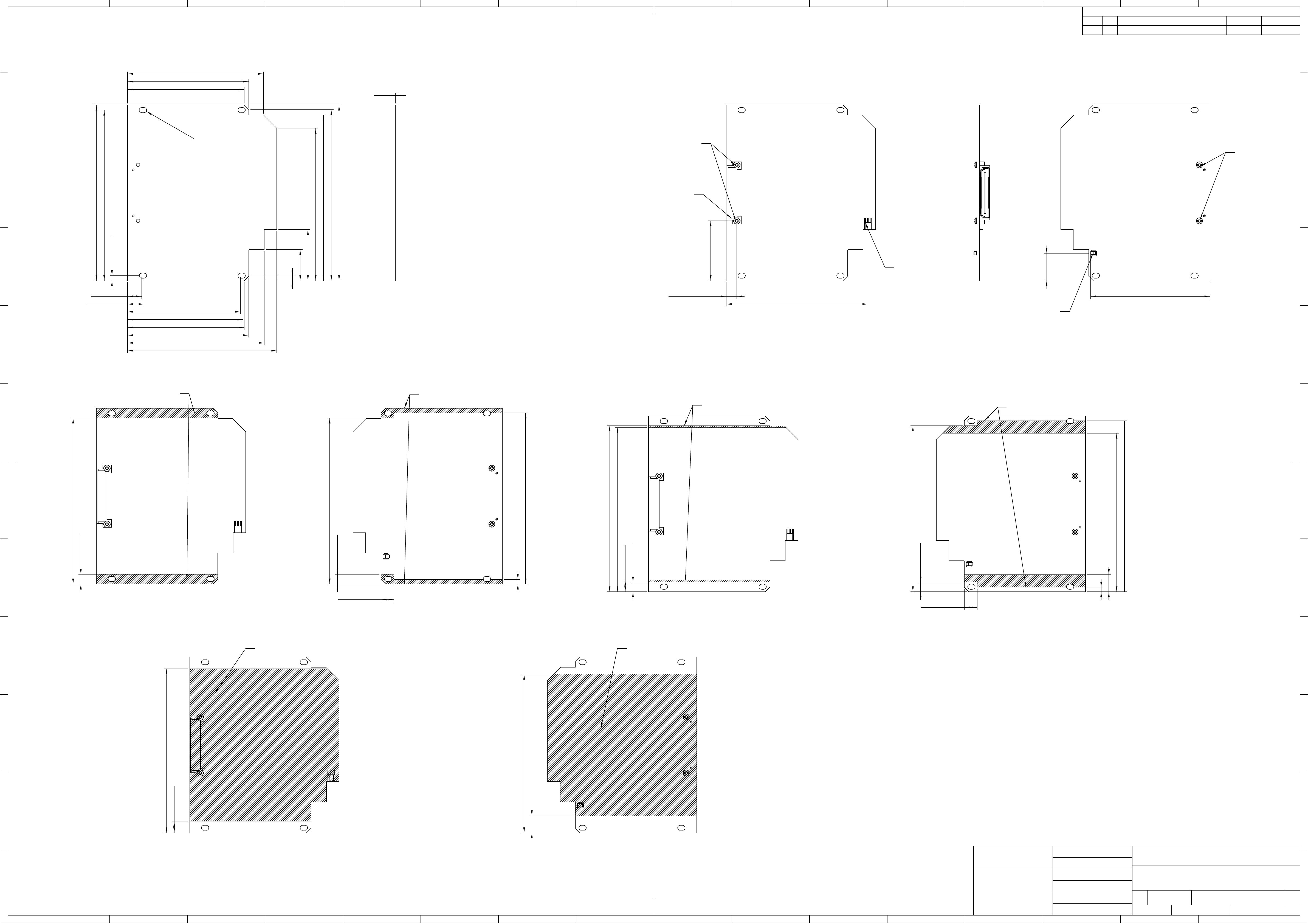
6.25
106.75
3
6.25
110
106.75
8.381
6.25
7.5
105.5
106.75
3
11
102
110
6.25
106.75
8.381
7.5
105.5
11
102
38.49
6.755
91.059
76.74
17.71
113
3
20
33.02
98
106.5
110
113
3.251
109.753
9.119
10.668
72.619
74.168
75
78
87.88
96
87.5
78
75 1.6
R
(8 PLCS)
1.626
Revisions
Zone Rev Description Date Approved
DIMENSIONS ARE IN
MILLIMETERS
FIRST ANGLE PROJECTION
CONTRACT NO
TOPCON POSITIONING SYSTEMS
INDL DSGNR
DUHFII Modem Layout
TOLERANCES
DECIMALS ANGLES
ENGR
DRAWN
TOPCON
SIZE FSCM NO. DWG NO. REV
CHECKED A1 1
DO NOT SCALE DRAWING SCALE 1:1 SHEET 1 of 1
Component Place Keepout Component Place Keepout
Component Height = 2.2 mm Max Component Height = 3.5 mm Max
Component Height = 7 mm Max Component Height = 5 mm Max
280173
280103
16-050909-01
280099
16-050910-01
Users Manual

Digital UHF II Radio Module
EXTERNAL DESIGN SPECIFICATION
Part Number 7010-xxxx
Rev. A
©Copyright Topcon Positioning Systems, Inc.
December, 2011
All contents in this manual are copyrighted by Topcon Positioning System, Inc. All rights reserved. The information
contained herein may not be used, accessed, copied, stored, displayed, sold, modified, published, or distributed, or
otherwise reproduced without express written consent from Topcon.

P/N 7010-xxxx i
TOC
Table of Contents
1 Introduction 1-1
Overview 1-1
Product Features 1-2
Operating Band, Channel Spacing, and Output Power 1-2
Modulation Technique 1-2
Physical Interfaces 1-2
Serial Data Interface 1-2
Link Status Indicators 1-3
Power Interface 1-3
RF Interface 1-3
Bluetooth Interface 1-3
Hardware Architecture 1-4
Functional Requirements 1-4
Electromagnetic Compliance 1-4
Electromagnetic Compatibility 1-5
Shielding Considerations 1-5
Frequency Planning 1-5
Mechanical Considerations 1-6
EMI interferers 1-6
Shock and Vibration 1-6
Thermal Transfer 1-6

Table of Contents
Digital UHF II EXTERNAL DESIGN SPECIFICATION
ii
Materials 1-6
2 Command Reference 2-1
Introduction 2-1
Intended Audience 2-1
Icons 2-2
Operating Modes 2-2
Firmware Images 2-3
Configuration Files 2-3
Factory configuration file 2-3
Dealer configuration file 2-3
Country configuration file 2-4
Commands 2-5
3 Specifications 3-1
Board Specifications 3-1
Interface Connector 3-4

P/N 7010-xxxx 1-1
Chapter 1
Introduction
Overview
DUHFII is a half duplex, UHF Radio Modem with built-in GSM/GPRS (or CDMA, HSPA) module
and Bluetooth transceiver developed to be integrated in a Topcon receiver. It takes incoming data from
a Topcon receiver through the standard serial port (CMOS/TTL compatible), modulates it with GMSK,
or 4FSK modulations and transmits it at RF power output levels from 10mW/10dBm to 1W/30dBm.
With 4FSK modulation, it will deliver error-free data at up to 19.2 kbps over the air for the 25 kHz
channel spacing and 9.6 kbps for 12.5 kHz.
The carrier frequency is the UHF commercial band of 400 MHz to 470 MHz. Channel spacing at 25
kHz, 20 kHz and 12.5 kHz are supported. The UHF transceiver is also capable of receiving RF signals
through a 50 Ohm impedance external antenna port. These signals are demodulated and output to the
Topcon receiver.
The modem requires a regulated DC voltage power supply from +6 to +14VDC with a maximum
current draw of 1.1A at 6VDC.
The incoming data could be also sent over the cellular network using built-in GSM/GPRS (or CDMA,
3G) module if such operation mode is selected.
The radio settings can be done through the built-in Command Line interface (CLI), or through the
configuration and maintenance application software running on the PC – “TRU”.
Note: The cell module option is currently not available. References to the cell module option in this
manual are for future configurations that have not been released.
Introduction
Digital UHF II EXTERNAL DESIGN SPECIFICATION
1-2
Product Features
Operating Band, Channel Spacing, and Output
Power
The following are its key benefits:
1. Single radio system covers the whole UHF frequency band from 400 to 470 MHz;
2. User selectable channel spacing (25kHz, 20kHz or 12.5kHz);
3. User selectable Output power level for base unit (10mW/10dBm and 1W/30dBm);
4. Programmable to limit operation to given frequency range or list of channels, given channel
spacing, given output power, RX mode.
Modulation Technique
The design is based on high-level modulation techniques which include:
Physical Interfaces
Serial Data Interface
The serial Data Interface can be configured through the software to operate in half and full duplex
operating modes. RTS, CTS, and CD signals should be reserved on-board for future support of full
UART hardware handshake operation. This will provide the support of the wide range of different
standard and none-standard, user specific, Data Link interfaces.
Modulation Technique 12.5 kHz 25 kHz
GMSK – Minimal Shift Keying with Gaussian Filtering 4.8 kbps 9.6 kbps 4.8 kbps 9.6 kbps
4FSK – Four Level Frequency Shift Keying 9.6 kbps 19.2 kbps 9.6 kbps 19.2 kbps
Physical Interfaces
P/N 7010-xxxx 1-3
Link Status Indicators
External LED’s are used for Link and Line status indication:
Power Interface
The power interface allows connection to an unregulated DC power source. The DC power source
(third party or user supplied) must provide peak 7.0 Watts of DC power between 6 and 14VDC. The
power interface is protected against reverse polarity connection, as well as protected against high-
voltage transients.
RF Interface
The RF interface is a 50-ohm impedance matched standard MMCX connector as required by
regulation. Switching from UHF to GSM/GPRS (or CDMA) operation mode and vice versa is
provided on RF interface.
Bluetooth Interface
Bluetooth antenna connector of Radial UMP series (R107003010) is used for Bluetooth antenna
attachment.
LED Name Color Description
TXA Green Active if modem transmits Data over radio link (min.
light on 200ms)
RXA Red Active if modem receives Data over radio link (min.
light on 200ms)
BLUETOOTH Blue Active if modem receives or transmits Data over
Bluetooth interface
WARNING
Before transmitting, always confirm that the antenna is connected.
Never transmit without the antenna or load connected.
WARNING
Mismatching of impedance between the DUHF II, antenna, and cable will cause a lesser transmit
power and result in a higher VSWR.

Introduction
Digital UHF II EXTERNAL DESIGN SPECIFICATION
1-4
Hardware Architecture
Functional Requirements
The UHF Modem/Cell/BT Board consists of the following main sections:
• UHF modem Tx/Rx modem;
• GSM/GPRS, 3G, or CDMA modules;
• Bluetooth module.
The block diagram of the DUHFII is presented below. In the figure, consider GSM modem as referring
to either GSM/GPRS or CDMA modules.
Electromagnetic Compliance
This device complies with part 15 of the FCC Rules. Operation is subject to the condition that this
device does not cause harmful interference.
NOTICE
The GSM/GPRS (or CDMA) module installation is optional. The mechanical design and software tools
provide easy way for GSM/GPRS module optional installation and configuration.
Electromagnetic Compatibility
P/N 7010-xxxx 1-5
Changes or modifications not expressly approved by the manufacturer could void the user’s authority
to operate the equipment.
Installation of Digital UHF II module into device shall comply with section 2.1091 of the FCC Rules.
If not possible to ensure that the separation between the user and the UHF antenna is greater than 30
cm, the user manual shall contain a statement warning the user to stay away from the UHF antenna by
30 cm at least when the UHF radio is operating in transmit mode.
UHF and Bluetooth antennas shall be shielded from the Digital UHF II module by the construction of
the device, so that not to cause harmful interference to the module.
Electromagnetic Compatibility
Shielding Considerations
The DUHF II transceiver is designed to operate in proximity to noise generating circuitry. However,
certain radiated or conducted frequencies may degrade the performance of the DUHF II transceiver or
render it inoperable. When possible, provide well-grounded shielding between circuits that radiate,
such as power supplies, voltage-controlled oscillators, crystal oscillators and the DUHF II transceiver.
Frequency Planning
Radiated and conducted signals to and from the DUHF II transceiver may cause problems due to
interference. Proper attention to frequency planning may reduce interference from radiated or
conducted frequencies that fall within the pass-bands of the filters at the IF frequencies.
It is recommended the use of upfront analysis of the product frequency plan (including harmonics) and
then the use of a spectrum analyzer to determine the potential for interference within the pass-bands of
the various front-end and band pass filters.
WARNING
The DUHF II is classified as an intentional radiator of type radio transceiver. Conducted and
radiated emissions of the standard DUHF II transceiver do not exceed the requirements of FCC
part 90. OEM is responsible for full compliance of final product.
WARNING
Frequencies ranging from 403 to 413 MHz may adversely affect GPS L2.
Do not use these frequencies with a Topcon GNSS receiver.

Introduction
Digital UHF II EXTERNAL DESIGN SPECIFICATION
1-6
Mechanical Considerations
EMI interferers
The DUHF II transceiver is easily mounted inside new and existing products. The DUHF II transceiver
is specifically designed for operation in harsh environments. For best performance, mount the radio
away from potential EMI radiators and route RF signals apart from digital signals.
Shock and Vibration
Sensitive radio transceivers, such as the DUHF II transceiver, are susceptible to interference due to
mechanical shock and vibration. To reduce the potential for electromechanical interference, a
robust mounting scheme must be used when being integrated into other systems.
Thermal Transfer
The DUHF II transceiver requires additional thermal heat dissipation in order to supply maximum
power out at elevated ambient temperatures and high duty cycles. The DUHF II transceiver has a
thermal sensor and a firmware controlled limit switch. The DUHF II will shut down when the PCB
temperature reaches 100°C to prevent permanent damage to transmitter. The DUHF II will produce
approximately 6 Watts of heat at full RF power out.
Materials
The DUHF II transceiver is housed in a metal shield that is a conductor and is electrically connected to
the ground and signal ground pins.
WARNING
It is not recommend the bundling of the antenna interface cable with other signal cables internal
to your product.

P/N 7010-xxxx 2-1
Chapter 2
Command Reference
Introduction
This command reference describes in detail all the commands available in version 1.2a9 of the
DUHFII firmware running on the Digital UHFII modems from Topcon Positioning Systems Inc. This
reference provides a very limited amount of feature descriptions, explanations of the technologies, or
configuration examples. For detailed information about the various features and technologies
supported by DUHFII modems, see “Introduction” on page 1-1.
Intended Audience
This reference is intended for system engineers, system designers, and programmers who are
communicating with the DUHFII modems using the command interface, and are designing or
implementing applications that use the DUHFII commands.

Command Reference
Digital UHF II EXTERNAL DESIGN SPECIFICATION
2-2
Icons
This reference includes icons that appear in the left margin and are designed to help you clearly
identify operating mode in which you can apply a particular command. The following icons are used
throughout this reference:
Operating Modes
The DUHFII modem can be operated in ether of the following modes:
• Factory – This mode is intended for the factory floor only. In this mode, factory personnel can
calibrate the modem and upload the factory firmware image and bootloader to it. The modem
enters Factory mode initially and brings out of this mode after a normal country configuration file
is uploaded.
• Dealer – This mode is intended for the dealers. In this mode, a dealer can load a dealer
configuration file to the modem. This file contains a customized set of parameters that the dealer
have selected to run on the modem. For details about the parameters available in this file, see
“Configuration Files” on page 2-3. The modem enters Dealer mode after a country configuration
file and brings out of this mode after a normal dealer configuration file is uploaded. Once the
modem brings out of Dealer mode, it automatically goes into User mode.
• User – This mode is intended for the end-users. In this mode, a user can apply the parameters
available in the dealer configuration file to the modem. For details about the parameters available
in the dealer configuration file, see “Configuration Files” on page 2-3. Note that every DUHFII
modem shipped to an end-user must be in User mode.
Keys Operating Mode
Command applies in Factory mode
only.
Command applies in Dealer mode
only.
Command applies in User mode only.

Firmware Images
P/N 7010-xxxx 2-3
Firmware Images
The DUHFII modem stores two firmware images; a factory and a user image.
• The factory image is the factory-installed firmware that is permanently available on the DUHFII
modem.
• The user image is the user-installed firmware that normally controls all modem operations,
including its normal boot process. If the modem boot process with the user image fails for any
reason, the modem can be booted with the factory image.
Initially, the modem is initialized with factory and user firmware images which are identical.
Configuration Files
The DUHFII modem stores three configuration files, specifically: factory configuration file, dealer
configuration file, and country configuration file.
Factory configuration file
This file stores modem calibration parameters and is generated only by the test bench on the factory
floor.
Dealer configuration file
The dealer configuration file limits the selection of frequencies, channel spacings and maximum
output power for an end user. Note that the allowed frequencies are defined by a list of specified
frequencies, not by the range.
typedef struct
{
unsigned int freq; // Hz
short reserved; // = 0
char spacing; // 0 - 25kHz, 1 - 12.5 kHz, 2 - 20 kHz
char max_power; // dBm
} t_U_Channels;
typedef union

Command Reference
Digital UHF II EXTERNAL DESIGN SPECIFICATION
2-4
Country configuration file
The country configuration file limits the range of allowed frequencies depending on the allocation of
RF bands in a specific country (region). It allows up to four contingent frequency ranges, each with its
own maximum output power and channel spacings.
{
t_U_Channels chan;
unsigned int crc32;
} t_User_Channels;
typedef struct
{
unsigned int DCFG; // 0x47464344 = DCFG signature
unsigned short version; // = 0
unsigned short number_of_channels; // 0-64 variable size structure
char callsign[32]; // zero terminated string
t_User_Channels item[64];
unsigned int crc32; // The CRC32 is a standard CRC with a
// polynomial of 0x04C11DB7, an initial
// value of 0xFFFFFFFF and an inverted
// output. The same algorithm is used in
// ZIP and RAR archives as well as in the
// ITU V.42 standard.
} t_DealerConfig;
typedef struct
{
unsigned int start_freq; // Hz, 0 if unused
unsigned int stop_freq; // Hz, 0 if unused
unsigned int spacing_enable_mask; // 0x00000001 - 25kHz,
// 0x00000002 - 12.5kHz,
// 0x00000004 - 20kHz
short reserved1; // = 0
char reserved2; // = 0
char max_power; // dBm, 10-30
} t_Freq_Ranges;
typedef struct
{
unsigned int CCFG; // 0x47464344 = CCFG signature
unsigned short version; // = 0, incompatible modifications will have
// different number
unsigned short reserved; // = 0
t_Freq_Ranges band[4]; // fixed size, not used ranges should be
// zero

Commands
P/N 7010-xxxx 2-5
Commands
This section lists the commands and subcommands supported by the DUHFII modem.
DATAMODE
++++
unsigned int crc32; // The CRC32 is a standard CRC with a
// polynomial of 0x04C11DB7, an initial
// value of 0xFFFFFFFF and an inverted
// output. The same algorithm is used in
// ZIP and RAR archives as well as in the
// ITU V.42 standard.
} t_CountryConfig;
Description: Switches the modem to data mode.
Access: write-only
Subcommands: This command has no subcommands.
Usage
Guidelines:
If the modem does not receive a command within 60
seconds, it will enter data mode.
When the modem generates test signals (TSTSGL
1...TSTSGL 6), the modem will remain in command
mode until you disable the test signals with the
command TSTSGL 0.
Command
Examples: DATAMODE
History: This command was introduced in the first release of
firmware.
Description: Switches the modem to command mode.
Access: write-only
Subcommands: This command has no subcommands.
Usage
Guidelines:
The guard time is 20 ms.
You can also enter command mode by asserting a DTR
line. To switch back to data mode, you must deassert the
DTR line. A 60-seconds timeout is disabled while the
DTR line is asserted.

Command Reference
Digital UHF II EXTERNAL DESIGN SPECIFICATION
2-6
LINK
LINK Subcommands:
MAP
RFSW
Command
Examples: ++++
History: This command was introduced in the first release of
firmware.
Description: Reports the current configuration of the RF data link.
Access: read-only
Subcommands: MAP, RFSW, MOD, PROT, PWRB, PWRW, SPACE,
CHAN, UCHAN, FREQ, SCRAM, FEC
Usage
Guidelines: This command has no usage guidelines.
Command
Examples:
LINK
LINK SPACE 0
History: This command was introduced in the first release of
firmware.
Description: Reports the channel map from the dealer list.
Access: read-only
Usage
Guidelines: This subcommand has no usage guidelines.
Command
Examples: LINK MAP
History: This subcommand was introduced in the first release of
firmware.
Description: Specifies the datalink type being used by the modem.
Access: read & write
Values: 0 – UHF
1 – GSM/GPRS
Usage
Guidelines: This subcommand has no usage guidelines.
Description: Switches the modem to command mode.
Access: write-only

Commands
P/N 7010-xxxx 2-7
MOD
PROT
Command
Examples:
LINK RFSW
LINK RFSW 1
History: This subcommand was introduced in the first release of
firmware.
Description: Specifies the modulation type being used by the modem.
Access: read & write
Values: 5 – GMSK
6 – 4LFSK
Usage
Guidelines: This subcommand has no usage guidelines.
Command
Examples:
LINK MOD
LINK MOD 6
History: This subcommand was introduced in the first release of
firmware.
Description: Specifies the radio protocol and whether the modem is
configured to transmit or receive data.
Access: read & write
Values:
7 – Trimble RX
8 – Trimble TX
11 – Trimble Repeater
12 – PDL RX
13 – PDL TX
14 – PDL RTR
15 – Satel RX
16 – Satel TX
17 – Satel Repeater
18 – Satel FCS On RX
19 – Satel FCS On TX
20 – Satel FCS On Repeater
Usage
Guidelines: This subcommand has no usage guidelines.
Command
Examples:
LINK PROT
LINK PROT 16
History: This subcommand was introduced in the first release of
firmware.
Description: Specifies the datalink type being used by the modem.
Access: read & write
Values: 0 – UHF
1 – GSM/GPRS

Command Reference
Digital UHF II EXTERNAL DESIGN SPECIFICATION
2-8
LINK Subcommands (Continued):
PWRB
PWRW
Description: Specifies the output power in dBm.
Access: read & write
Values: [10...30]
Usage
Guidelines:
The restrictions from the country and/or dealer
configuration files may apply.
Although you may specify any output power within its
range of allowed values, only the following values are
factory-calibrated and thus recommended for use:10, 13,
17, 20, 23, 27, 30.
Command
Examples:
LINK PWRB
LINK PWRB 20
History: This subcommand was introduced in the first release of
firmware.
Description: Specifies the output power in mW.
Access: read & write
Values: [10...1000]
Usage
Guidelines:
Reading will return a value rounded to the nearest integer
value in mW.
The restrictions from the country and/or dealer
configuration files may apply.
Although you may specify any output power within its
range of allowed values, only the following values are
factory-calibrated and thus recommended for use: 10, 20,
50, 100, 200, 500, 1000.
Command
Examples:
LINK PWRW
LINK PWRW 500
History: This subcommand was introduced in the first release of
firmware.

Commands
P/N 7010-xxxx 2-9
LINK Subcommands (Continued):
SPACE
CHAN
UCHAN
Description: Specifies the channel spacing in kHz.
Access: read & write
Values:
0 – 25 kHz
1 – 12.5 kHz
2 – 20 kHz
Usage
Guidelines:
The restrictions from the country and/or dealer
configuration files may apply.
Command
Examples:
LINK SPACE
LINK SPACE 1
History: This subcommand was introduced in the first release of
firmware.
Description: Specifies the frequency channel.
Access: read & write
Values: [1...9601]
Usage
Guidelines:
For 25 and 12.5 kHz spacings, the following formula is used to
relate the frequency and its frequency channel:
FRQ=410000000+(n-1)*6250, where n is the frequency channel.
For 20 kHz spacing, the following formula is used to relate the
frequency and its frequency channel: FRQ=410000000+(n-
10001)*5000, where n is the frequency channel.
The restrictions from the country and/or dealer configuration files
may apply.
Command
Examples:
LINK CHAN
LINK CHAN 1
History: This subcommand was introduced in the first release of firmware.
Description: Selects channel settings from the dealer list.
Access: read & write
Values: [0...63]
Usage
Guidelines: This subcommand has no usage guidelines.
Command
Examples:
LINK UCHAN
LINK UCHAN 12
History: This subcommand was introduced in the first release of firmware.

Command Reference
Digital UHF II EXTERNAL DESIGN SPECIFICATION
2-10
LINK Subcommands (Continued):
FREQ
SCRAM
FEC
Description: Specifies the channel frequency.
Access: read & write
Values: [390000000...480000000]
Usage
Guidelines:
The frequency will be rounded to the nearest available channel
depending on channel spacing. An actual frequency range will be
defined by Country Configuration.
The restrictions from the country and/or dealer configuration files
may apply.
Command
Examples:
LINK FREQ
LINK FREQ 420000000
History: This subcommand was introduced in the first release of firmware.
Description: Configures scrambling.
Access: read & write
Values:
[0...255]
0 – disabled
[1...255] – scrambling enabled
Usage
Guidelines:
Scrambling is always enabled for TrimTalk.
Scrambling is always disabled for Satel.
Command
Examples:
LINK SCRAM
LINK SCRAM 1
History: This subcommand was introduced in the first release of firmware.
Description: Configures forward error correction.
Access: read & write
Values: 0 – disabled
1 – enabled
Usage
Guidelines:
FEC is supported for PDL and Satel.
FEC is always disabled for TrimTalk.
Command
Examples:
LINK FEC
LINK FEC 1
History: This subcommand was introduced in the first release of firmware.

Commands
P/N 7010-xxxx 2-11
LINK Subcommands (Continued):
ATI
ATI Subcommands:
ID
SN
Description: Displays the firmware and hardware details.
Access: read-only
Subcommands: ID, SN, HW, SW, BL
Usage
Guidelines: This command has no usage guidelines.
Command
Examples: ATI
History: This command was introduced in the first release of
firmware.
Description: Displays the product ID.
Access: read-only
Usage
Guidelines: This subcommand has no usage guidelines.
Command
Examples: ATI ID
History: This subcommand was introduced in the first release of
firmware.
Description: Displays the serial number.
Access: read-only
Usage
Guidelines: This subcommand has no usage guidelines.
Command
Examples: ATI SN
History: This subcommand was introduced in the first release of
firmware.

Command Reference
Digital UHF II EXTERNAL DESIGN SPECIFICATION
2-12
ATI Subcommands (Continued):
HW
SW
BL
Description: Displays the hardware revision.
Access: read-only
Usage
Guidelines: This subcommand has no usage guidelines.
Command
Examples: ATI HW
History: This subcommand was introduced in the first release of
firmware.
Description: Displays the software revision.
Access: read-only
Usage
Guidelines: This subcommand has no usage guidelines.
Command
Examples: ATI SW
History: This subcommand was introduced in the first release of
firmware.
Description: Displays the bootloader version.
Access: read-only
Usage
Guidelines: This subcommand has no usage guidelines.
Command
Examples: ATI BL
History: This subcommand was introduced in the first release of
firmware.

Commands
P/N 7010-xxxx 2-13
ATI Subcommands (Continued):
STATE
STATE Subcommands:
RSSI
BER
Description: Displays the current state.
Access: read-only
Subcommands: RSSI, BER, FREQ, CHAN, UCHAN, TEMP, MODE,
BAND, PWRB
Usage
Guidelines: This command has no usage guidelines.
Command
Examples: STATE
History: This command was introduced in the first release of
firmware.
Description: Displays the RSSI level.
Access: read-only
Usage
Guidelines: This subcommand has no usage guidelines.
Command
Examples: STATE RSSI
History: This subcommand was introduced in the first release of
firmware.
Description: Displays the bit error rate.
Access: read-only
Usage
Guidelines: This subcommand has no usage guidelines.
Command
Examples: STATE BER
History: This subcommand was introduced in the first release of
firmware.

Command Reference
Digital UHF II EXTERNAL DESIGN SPECIFICATION
2-14
STATE Subcommands (Continued):
FREQ
CHAN
UCHAN
Description: Displays the frequency.
Access: read-only
Usage
Guidelines: This subcommand has no usage guidelines.
Command
Examples: STATE FREQ
History: This subcommand was introduced in the first release of
firmware.
Description: Displays the channel number.
Access: read-only
Usage
Guidelines: This subcommand has no usage guidelines.
Command
Examples: STATE CHAN
History: This subcommand was introduced in the first release of
firmware.
Description: Displays the user-selected channel number.
Access: read-only
Usage
Guidelines: This subcommand has no usage guidelines.
Command
Examples: STATE UCHAN
History: This subcommand was introduced in the first release of
firmware.

Commands
P/N 7010-xxxx 2-15
STATE Subcommands (Continued):
TEMP
MODE
BAND
Description: Displays the modem temperature.
Access: read-only
Usage
Guidelines: This subcommand has no usage guidelines.
Command
Examples: STATE TEMP
History: This subcommand was introduced in the first release of
firmware.
Description: Displays the current operating mode.
Access: read-only
Values:
1 – Factory mode
2 – Dealer mode
3 – User mode
Usage
Guidelines: This subcommand has no usage guidelines.
Command
Examples: STATE MODE
History: This subcommand was introduced in the first release of
firmware.
Description: Displays the current frequency and spacing limits.
Access: read-only
Usage
Guidelines: This subcommand has no usage guidelines.
Command
Examples: STATE BAND
History: This subcommand was introduced in the first release of
firmware.

Command Reference
Digital UHF II EXTERNAL DESIGN SPECIFICATION
2-16
STATE Subcommands (Continued):
PWRB
@ECHO
DPORT
Description: Displays the output power.
Access: read-only
Usage
Guidelines: This subcommand has no usage guidelines.
Command
Examples: STATE PWRB
History: This subcommand was introduced in the first release of
firmware.
Description: Configures echo for command mode.
Access: read & write
Values: ON – Echo on
OFF – Echo off
Subcommands: This command has no subcommands.
Usage
Guidelines: This command has no usage guidelines.
Command
Examples: @ECHO ON
History: This command was introduced in the first release of
firmware.
Description: Displays parameters for the serial port in Data mode.
Access: read-only
Subcommands: RATE, BITS, PARITY, FLOW, STOP
Usage
Guidelines: This command has no usage guidelines.
Command
Examples: DPORT
History: This command was introduced in the first release of
firmware.

Commands
P/N 7010-xxxx 2-17
DPORT Subcommands:
RATE
BITS
Description: Configures the baud rate.
Access: read & write
Values:
0 – equals MPORT RATE
1 – 1200
2 – 2400
3 – 4800
4 – 9600
5 – 14400
6 – 19200
7 – 38400
8 – 57600
9 – 115200
Usage
Guidelines: This subcommand has no usage guidelines.
Command
Examples: DPORT RATE 7
History: This subcommand was introduced in the first release of
firmware.
Description: Configures the number of data bits.
Access: read & write
Values: 7, 8
Usage
Guidelines: This subcommand has no usage guidelines.
Command
Examples: DPORT BITS 7
History: This subcommand was introduced in the first release of
firmware.

Command Reference
Digital UHF II EXTERNAL DESIGN SPECIFICATION
2-18
DPORT Subcommands (Continued):
PARITY
FLOW
STOP
Description: Configures the parity.
Access: read & write
Values:
0 – none
1 – odd
2 – even
Usage
Guidelines: This subcommand has no usage guidelines.
Command
Examples: DPORT PARITY 1
History: This subcommand was introduced in the first release of
firmware.
Description: Configures the handshaking.
Access: read & write
Values:
0 – none
1 – unused
2 – RTS/CTS
Usage
Guidelines: This subcommand has no usage guidelines.
Command
Examples: DPORT FLOW 2
History: This subcommand was introduced in the first release of
firmware.
Description: Configures the number of stop bits.
Access: read & write
Values: 1 – 1 stop bit
2 – 2 stop bits
Usage
Guidelines: This subcommand has no usage guidelines.
Command
Examples: DPORT STOP 1
History: This subcommand was introduced in the first release of
firmware.

Commands
P/N 7010-xxxx 2-19
DPORT Subcommands (Continued):
MPORT
MPORT Subcommands:
RATE
Description: Displays parameters for the serial port in Maintenance
(command) mode.
Access: read-only
Subcommands: RATE, BITS, PARITY, FLOW, STOP
Usage
Guidelines: This command has no usage guidelines.
Command
Examples: DPORT
History: This command was introduced in the first release of
firmware.
Description: Configures the baud rate.
Access: read & write
Values:
0 – equals MPORT RATE
1 – 1200
2 – 2400
3 – 4800
4 – 9600
5 – 14400
6 – 19200
7 – 38400
8 – 57600
9 – 115200
Usage
Guidelines: This subcommand has no usage guidelines.
Command
Examples: MPORT RATE 7
History: This subcommand was introduced in the first release of
firmware.

Command Reference
Digital UHF II EXTERNAL DESIGN SPECIFICATION
2-20
MPORT Subcommands (Continued):
BITS
PARITY
FLOW
Description: Configures the number of data bits.
Access: read & write
Values: 7, 8
Usage
Guidelines: This subcommand has no usage guidelines.
Command
Examples: MPORT BITS 7
History: This subcommand was introduced in the first release of
firmware.
Description: Configures the parity.
Access: read & write
Values:
0 – none
1 – odd
2 – even
Usage
Guidelines: This subcommand has no usage guidelines.
Command
Examples: MPORT PARITY 1
History: This subcommand was introduced in the first release of
firmware.
Description: Configures the handshaking.
Access: read & write
Values:
0 – none
1 – unused
2 – RTS/CTS
Usage
Guidelines: This subcommand has no usage guidelines.
Command
Examples: MPORT FLOW 2
History: This subcommand was introduced in the first release of
firmware.

Commands
P/N 7010-xxxx 2-21
MPORT Subcommands (Continued):
STOP
SAVE
RESTORE
Description: Configures the number of stop bits.
Access: read & write
Values: 1 – 1 stop bit
2 – 2 stop bits
Usage
Guidelines: This subcommand has no usage guidelines.
Command
Examples: MPORT STOP 1
History: This subcommand was introduced in the first release of
firmware.
Description: Stores the current settings to Flash memory.
Access: write-only
Subcommands: This command has no subcommands.
Usage
Guidelines: This command has no usage guidelines.
Command
Examples: SAVE
History: This command was introduced in the first release of
firmware.
Description: Restores the default settings.
Access: write-only
Subcommands: This command has no subcommands.
Usage
Guidelines: This command has no usage guidelines.
Command
Examples: RESTORE
History: This command was introduced in the first release of
firmware.

Command Reference
Digital UHF II EXTERNAL DESIGN SPECIFICATION
2-22
PROTIME
TCXO
ALC
Description: Configures the protocol timeout.
Access: read & write
Values: [10...255]
Subcommands: This command has no subcommands.
Usage
Guidelines: This command has no usage guidelines.
Command
Examples: PROTIME 15
History: This command was introduced in the first release of
firmware.
Description: Adjusts oscillator offset.
Access: read & write
Values: [0...32]
Subcommands: This command has no subcommands.
Usage
Guidelines: This command has no usage guidelines.
Command
Examples: TCXO 20
History: This command was introduced in the first release of
firmware.
Description: Configures transmitter gains.
Access: read-only
Subcommands: A, B, D, X, Y
Usage
Guidelines: This command has no usage guidelines.
Command
Examples: ALC
History: This command was introduced in the first release of
firmware.

Commands
P/N 7010-xxxx 2-23
ALC Subcommands:
A
B
D
Description: Configures the pre-amplifier gain.
Access: read & write
Values: [0...31]
Usage
Guidelines: This subcommand has no usage guidelines.
Command
Examples:
ALC A
ALC A 12
History: This subcommand was introduced in the first release of
firmware.
Description: Configures the amplifier gain.
Access: read & write
Values: [0...32]
Usage
Guidelines: This subcommand has no usage guidelines.
Command
Examples:
ALC B
ALC B 10
History: This subcommand was introduced in the first release of
firmware.
Description: Configures the DAC gain.
Access: read & write
Values: [0...32767]
Usage
Guidelines: This subcommand has no usage guidelines.
Command
Examples:
ALC D
ALC D 15343
History: This subcommand was introduced in the first release of
firmware.

Command Reference
Digital UHF II EXTERNAL DESIGN SPECIFICATION
2-24
ALC Subcommands (Continued):
X
Y
CSAVE
Description: Configures the TX modulator offset.
Access: read & write
Values: [-4096...4095]
Usage
Guidelines: This subcommand has no usage guidelines.
Command
Examples:
ALC X
ALC X -4090
History: This subcommand was introduced in the first release of
firmware.
Description: Configures the TX modulator offset.
Access: read & write
Values: [-4096...4095]
Usage
Guidelines: This subcommand has no usage guidelines.
Command
Examples:
ALC Y
ALC Y 4090
History: This subcommand was introduced in the first release of
firmware.
Description: Stores the current ALC values to the calibration table.
Access: write-only
Subcommands: This command has no subcommands.
Usage
Guidelines: Used for manual calibration.
Command
Examples: CSAVE
History: This command was introduced in the first release of
firmware.

Commands
P/N 7010-xxxx 2-25
TSTSGL
FCS
FCS Subcommands:
CHANCLR
Description: Configures test signals.
Access: write-only
Values: [0...6]
Subcommands: This command has no subcommands.
Usage
Guidelines: This command has no usage guidelines.
Command
Examples: TSTSGL 3
History: This command was introduced in the first release of
firmware.
Description: Configures the protocol timeout.
Access: read-only
Subcommands: CHANCLR, NETID, RXLT, BI, BDT, CHANON,
CHANOFF, RSSI
Usage
Guidelines: This command applies to Satel protocol only.
Command
Examples: FCS
History: This command was introduced in the first release of
firmware.
Description: Clears the channel list.
Access: write-only
Usage
Guidelines: This subcommand has no usage guidelines.
Command
Examples: FCS CHANCLR
History: This subcommand was introduced in the first release of
firmware.

Command Reference
Digital UHF II EXTERNAL DESIGN SPECIFICATION
2-26
FCS Subcommands (Continued):
NETID
RXLT
BI
Description: Configures network ID.
Access: read & write
Values: [0x0000...0xFFFF]
Usage
Guidelines: This subcommand has no usage guidelines.
Command
Examples: FCS NETID 0x0000
History: This subcommand was introduced in the first release of
firmware.
Description: Configures the RX listen timeout.
Access: read & write
Values: [0...65535]
Usage
Guidelines: This subcommand has no usage guidelines.
Command
Examples: FCS RXLT 30
History: This subcommand was introduced in the first release of
firmware.
Description: Configures the beacon interval.
Access: read & write
Values: [0...65535]
Usage
Guidelines: This subcommand has no usage guidelines.
Command
Examples: FCS BI 50
History: This subcommand was introduced in the first release of
firmware.

Commands
P/N 7010-xxxx 2-27
FCS Subcommands (Continued):
BDT
CHANON
CHANOFF
Description: Configures the beacon disable timeout.
Access: read & write
Values: [0...65535]
Usage
Guidelines: This subcommand has no usage guidelines.
Command
Examples: FCS BDT 60
History: This subcommand was introduced in the first release of
firmware.
Description: Enables FCS for the selected channel.
Access: write-only
Values: [0...47]
Usage
Guidelines: This subcommand has no usage guidelines.
Command
Examples: FCS CHANON 9
History: This subcommand was introduced in the first release of
firmware.
Description: Disables FCS for the selected channel.
Access: write-only
Values: [0...47]
Usage
Guidelines: This subcommand has no usage guidelines.
Command
Examples: FCS CHANOFF 9
History: This subcommand was introduced in the first release of
firmware.

Command Reference
Digital UHF II EXTERNAL DESIGN SPECIFICATION
2-28
FCS Subcommands (Continued):
RSSI
ADDR
ADDR Subcommands:
TXEN
Description: Configures the RSSI threshold.
Access: read & write
Values: [80...118]
Usage
Guidelines: This subcommand has no usage guidelines.
Command
Examples: FCS RSSI 95
History: This subcommand was introduced in the first release of
firmware.
Description: Displays Satel protocol routing.
Access: read-only
Subcommands: TXEN, RXEN, TXAUTO, RX2RS, TXP, RXP, TXS,
RXS
Usage
Guidelines: This command applies to Satel protocol only.
Command
Examples: ADDR
History: This command was introduced in the first release of
firmware.
Description: Configures address transmission.
Access: write-only
Values: 1, 0
Usage
Guidelines: This subcommand has no usage guidelines.
Command
Examples: ADDR TXEN 1
History: This subcommand was introduced in the first release of
firmware.

Commands
P/N 7010-xxxx 2-29
ADDR Subcommands (Continued):
RXEN
TXAUTO
RX2RS
Description: Configures address receiving.
Access: write-only
Values: 1, 0
Usage
Guidelines: This subcommand has no usage guidelines.
Command
Examples: ADDR RXEN 1
History: This subcommand was introduced in the first release of
firmware.
Description: Configures transmission address auto switch.
Access: write-only
Values: 1, 0
Usage
Guidelines: This subcommand has no usage guidelines.
Command
Examples: ADDR TXAUTO 1
History: This subcommand was introduced in the first release of
firmware.
Description: Configures received address to RS port.
Access: write-only
Values: 1, 0
Usage
Guidelines: This subcommand has no usage guidelines.
Command
Examples: ADDR RX2RS 1
History: This subcommand was introduced in the first release of
firmware.

Command Reference
Digital UHF II EXTERNAL DESIGN SPECIFICATION
2-30
ADDR Subcommands (Continued):
TXP
RXP
TXS
Description: Configures the transmission primary address.
Access: read & write
Values: [0x0000...0xFFFF]
Usage
Guidelines: This subcommand has no usage guidelines.
Command
Examples: ADDR TXP 0x0000
History: This subcommand was introduced in the first release of
firmware.
Description: Configures the receiving primary address.
Access: read & write
Values: [0x0000...0xFFFF]
Usage
Guidelines: This subcommand has no usage guidelines.
Command
Examples: ADDR RXP 0x0000
History: This subcommand was introduced in the first release of
firmware.
Description: Configures the transmission secondary address.
Access: read & write
Values: [0x0000...0xFFFF]
Usage
Guidelines: This subcommand has no usage guidelines.
Command
Examples: ADDR TXS 0x0001
History: This subcommand was introduced in the first release of
firmware.

Commands
P/N 7010-xxxx 2-31
ADDR Subcommands (Continued):
RXS
TXDELAY
HELP
Description: Configures the receiving secondary address.
Access: read & write
Values: [0x0000...0xFFFF]
Usage
Guidelines: This subcommand has no usage guidelines.
Command
Examples: ADDR RXS 0x0002
History: This subcommand was introduced in the first release of
firmware.
Description: Configures transmit delay.
Access: read & write
Values: [0...65535]
Subcommands: This command has no subcommands.
Usage
Guidelines: This command has no usage guidelines.
Command
Examples: TXDELAY 20
History: This command was introduced in the first release of
firmware.
Description: Displays commands and their description.
Access: read-only
Subcommands: This command has no subcommands.
Usage
Guidelines: This command has no usage guidelines.
Command
Examples: HELP
History: This command was introduced in the first release of
firmware.

Command Reference
Digital UHF II EXTERNAL DESIGN SPECIFICATION
2-32
XMOD
XMOD Subcommands:
IMAGE
FACTIMAGE
Description: Uploads firmware and configuration files to the modem
using the X-Modem protocol.
Access: read-only
Subcommands: IMAGE, FACTIMAGE, LOADER, DDFG, DCCFG,
DFCFG
Usage
Guidelines:
To start uploading, you need to supply this command
with the corresponding subcommand.
Command
Examples: XMOD
History: This command was introduced in the first release of
firmware.
Description: Uploads user firmware.
Access: write-only
Usage
Guidelines: This subcommand has no usage guidelines.
Command
Examples: XMOD IMAGE
History: This subcommand was introduced in the first release of
firmware.
Description: Uploads factory firmware.
Access: write-only
Usage
Guidelines: This subcommand has no usage guidelines.
Command
Examples: XMOD FACTIMAGE
History: This subcommand was introduced in the first release of
firmware.

Commands
P/N 7010-xxxx 2-33
XMOD Subcommands (Continued):
DDCFG
DCCFG
DFCFG
BOOT
Description: Uploads dealer configuration in TPS format.
Access: write-only
Usage
Guidelines:
Successful loading will switch the modem from dealer to
user mode.
Command
Examples: XMOD DDCFG
History: This subcommand was introduced in the first release of
firmware.
Description: Uploads country configuration.
Access: write-only
Usage
Guidelines:
Successful loading will switch the modem from factory to
dealer mode.
Command
Examples: XMOD DCCFG
History: This subcommand was introduced in the first release of
firmware.
Description: Uploads factory calibration settings.
Access: write-only
Usage
Guidelines: This subcommand has no usage guidelines.
Command
Examples: XMOD DFCFG
History: This subcommand was introduced in the first release of
firmware.
Description: Reboots the modem.
Access: write-only
Subcommands: IMAGE, CFG
Usage
Guidelines: This command has no usage guidelines.

Command Reference
Digital UHF II EXTERNAL DESIGN SPECIFICATION
2-34
BOOT Subcommands:
IMAGE
CFG
Command
Examples: BOOT
History: This command was introduced in the first release of
firmware.
Description: Reboots the modem and selects a copy of firmware.
Access: write-only
Values: 0 – Factory firmware
1 – User firmware
Usage
Guidelines: This subcommand has no usage guidelines.
Command
Examples: BOOT IMAGE 1
History: This subcommand was introduced in the first release of
firmware.
Description: Reboots the modem and selects a configuration.
Access: write-only
Values: 0 – Factory configuration
1 – User configuration
Usage
Guidelines: This subcommand has no usage guidelines.
Command
Examples: BOOT CFG 1
History: This subcommand was introduced in the first release of
firmware.
Description: Reboots the modem.
Access: write-only

P/N 7010-xxxx 3-1
Chapter 3
Specifications
Board Specifications
General
Radio interfaces UHF 400 – 470 MHz
Bluetooth (optional)
GSM/GPRS 850/900/1800/1900 (optional)
CDMA 1xRTT 800/1900 (optional)
HSPA 850/900/1700/1900/2100 (optional)
Simultaneous operation Bluetooth / UHF - yes
Bluetooth / GSM (CDMA, HSPA) – yes
UHF / GSM (CDMA, HSPA) - no
Bluetooth TAYUO YUDEN EYSF3CAVX
2.0+EDR
GSM/GPRS Motorola G24
CDMA Motorola C24
HSPA Motorola H24

Specifications
Digital UHF II EXTERNAL DESIGN SPECIFICATION
3-2
Compliance FCC 47CFR PT 15.247
FCC 47CFR PT 90
IC RSS 119
ETSI EN 300-113-2 V1.6.1 (in enclosure only)
EN 300 328 (in enclosure only)
ETSI EN 301 489-1 V1.9.2
ETSI EN 301 489-5 V1.3.1
ETSI EN 301 489-17 V2.1.1
Interface
Antenna connector UHF/GSM/
CDMA/HSPA
MMCX, Molex 73415-1001 or similar
Antenna connector Bluetooth RADIALL R107 003 010
Interface RS-232
Data Speed of Interface 300 to 115200 bps
Interface Connector 2x26 (pinout see below)
Operating Voltage 6-14 Vdc
UHF Transceiver
Operating Frequency Range 400 – 470 MHz
Modulation Technique GMSK, 4FSK
Protocol Satel (without FCS)
Configuration Programmable to limit operation to given frequency range or list of channels, given channel
spacing, given output power, RX mode
Max. Distance Range 15 miles/24 km
Occupied Bandwidth (Channel
Spacing)
25 kHz, 20 kHz or 12.5 kHz (user selectable)
Data Rate (@25 kHz Channel
Spacing)
9600 bps –GMSK
19200 bps –4FSK
Data Rate (@20 kHz Channel
Spacing)
4800 bps –GMSK
9600 bps –4FSK
Data Rate (@12.5 kHz Channel
Spacing)
4800 bps –GMSK
9600 bps –4FSK
System Gain (Antenna gain is not
included):
GMSK
4FSK
149 dB (for 25 kHz Channel Spacing)
152 dB (for 12.5 kHz Channel Spacing)
147 dB (for 25 kHz Channel Spacing)
150 dB (for 12.5 kHz Channel Spacing
Roaming Speed 60 mph/96 km/h
End to End delay 60 ms
Power Consumption at 6 V 8.4 V 12 V
Max power consumption in RX
mode, W 1.8 1.9 2.3

Board Specifications
P/N 7010-xxxx 3-3
Max power consumption in TX
mode with 1W output, W 6.5 6.5 7.0
Max current in RX mode, A 0.3 0.23 0.17
Max current in TX mode, A 1.1 0.78 0.5
Compliance FCC Part 90
IC RSS 119
ETSI EN 300-113-2 V1.6.1
ETSI EN 301 489-1 V1.9.2
ETSI EN 301 489-5 V1.3.1
ETSI EN 301 489-17 V2.1.1
UHF Transmitter
Output Power 10, 13, 17, 20, 27, 30 dBm (user selectable)
Output Power Control Accuracy ±1.5 dB (at normal test conditions)
+2.0 dB and -3.0 dB (under extreme test conditions)
Nominal Output Impedance 50 Ohm
VSWR 2.0:1
Carrier Frequency Stability ±1.5 ppm initial stability over temp with ±3 ppm aging/year
Max. Frequency Error ±1.5 kHz (at normal test conditions)
±2.5 kHz (under extreme test conditions)
Adjacent Channel Power Below -37 dBm
Spurious Emission (Conducted and
Radiated)
frequency range 9 kHz – 1 GHz
frequency range 1 GHz – 12.75 GHz
Below -36 dBm
Below -30 dBm
Type of Emission F1D
FCC Part 90
§90.210(c) for 25 kHz Channel Spacing
§90.210(d) for 12.5 kHz Channel Spacing
ETSI EN 300-113-1 V1.5.1
Clause 5.1.4
Clause 8.6.1
UHF Receiver
Nominal Input Impedance 50 Ohm
Receiver Sensitivity for GMSK
(@ BER <1x 10⁻⁴, over temperature
-30oC to +60oC)
-119 dBm for 25 kHz Channel Spacing
-122 dBm for 12.5 kHz Channel Spacing
Receiver Sensitivity for 4FSK
(@ BER <1x 10⁻⁴, over temperature
-30oC to +60oC)
-117 dBm for 25 kHz Channel Spacing
-118 dBm for 20 kHz Channel Spacing
-120 dBm for 12.5 kHz Channel Spacing
Dynamic Range -119 to -1 dBm for GMSK
-117 to -1 dBm for 4FSK
Max. Input Signal Level -1 dBm

Specifications
Digital UHF II EXTERNAL DESIGN SPECIFICATION
3-4
Interface Connector
The main interface connector is a 56-pin header connector of FX5 series, HIROSE FX5-52P-SH (71).
Spurious Emission (Conducted and
Radiated)
frequency range 9 kHz – 1 GHz
frequency range 1 GHz – 12.75 GHz
Below -57 dBm
Below -47 dBm
Environmental
Temperature: FCC/ETSI compliant
operation range
-25 to +55 ºC
Temperature: operation range -30 to +60 ºC
Temperature: storage -40 to +85 ºC
Pin Name In/Out Level Description
A1 GND - GND
A2 GND - GND
A3 POWER_IN In +6...14 Vdc Power Supply
A4 POWER_IN In +6...14 Vdc Power Supply
A5 SPI_CSB In TTL SPI Chip Select (Active Low, Not Connected)
A6 SPI_MISO Out TTL Data from Bluetooth to Host (Not Connected)
A7 SPI_CLK In TTL CLOCK from Host to Bluetooth (Not Connected)
A8 RED Out HighZ/+3.3Vdc RXA LED Anode
A9 GRN Out HighZ/+3.3Vdc TXA LED Anode
A11 RTSA Out TTL Asserted by Radio Modem Clear To Send (CTS) data flow
control signal wired to RTS input on Topcon Receiver (Serial
Port A):
• 0VDC = Modem’s Transmit buffer not full, continue data
transferring
• 3.3VDC = Modem’s Transmit buffer full, stop data
transferring
A12 CTSA In TTL Asserted by Topcon Receiver data flow control signal to
Request To Send (RTS) data over Serial Port A:
• 0VDC = Receive Data from Modem is enabled
• 3.3VDC = Receive Data from Modem is disabled

Interface Connector
P/N 7010-xxxx 3-5
A13 RTSB Out TTL Asserted by Bluetooth transceiver Clear To Send (CTS) data
flow control signal wired to RTS input on Topcon Receiver
(Serial Port B):
• 0VDC = Bluetooth Transmit buffer not full, continue
transmitting
• 3.3VDC = Bluetooth Transmit buffer full, stop data
transferring
A14 CTSB In TTL Asserted by Topcon Receiver data flow control signal to
Request To Send (RTS) data over Serial Port B:
• 0VDC = Receive Data from Bluetooth is enabled
• 3.3VDC = Receive Data from Bluetooth is disabled
A15 GND - GND
A18 SIMRST Out Logic SIM Reset active LOW
A19 SIMCLK Out Logic SIM Clock
A20 SIMPRES In Logic SIM Presence active LOW
A22 PWR_ON In 0...+3.3 Vdc Radio modem ON/OFF control
• 0VDC = OFF
• 3.3VDC = ON
A23 POWER_IN In +6...14 Vdc Power Supply
A24 POWER_IN In +6...14 Vdc Power Supply
A25 GND - GND
A26 GND - GND
B1 GND - GND
B2 GND - GND
B3 POWER_IN In +6...14 Vdc Power Supply
B4 POWER_IN In +6...14 Vdc Power Supply
B5 SPI_MOSI In TTL Data from Host to Bluetooth (Not Connected)
B6 RESET_BT In TTL Reset of Bluetooth module (Active High, Not Connected)
B8 BLUE Out HighZ/+3.3Vdc Bluetooth LED Anode
B9 GND - GND
B11 TXA Out TTL Data TO Topcon Receiver FROM radio modem
B12 RXA In TTL Data FROM Topcon Receiver TO radio modem
B13 TXB Out TTL Data TO Topcon Receiver FROM Bluetooth
B14 RXB In TTL Data FROM Topcon Receiver TO Bluetooth
B15 GND - GND
B16 PROG In 0...+3.3 Vdc Must be normally UNCONNECTED or higher than
+3.0VDC. Connect to ground to update the program flash.
B18 SIMDATA In/Out Logic SIM serial data
Pin Name In/Out Level Description

Specifications
Digital UHF II EXTERNAL DESIGN SPECIFICATION
3-6
B19 SIMVCC Out +2.85...+3.1 Vdc SIM VCC
B20 GND - GND
B21 3V3 Out +3.3 Vdc Power Supply +3.3 Vdc, 20 mA
B23 POWER_IN In +6...14 Vdc Power Supply
B24 POWER_IN In +6...14 Vdc Power Supply
B25 GND - GND
B26 GND - GND
Pin Name In/Out Level Description

F
8
E
D
C
B
A
G
H
J
K
L
M
7654321 9 10 11 12 13 14 15 16
91 2 3 4 5 6 7 8 10 11 12
K
G
A
B
C
D
E
F
H
J
13 1514 16
M
L
6.25
106.75
3
6.25
110
106.75
8.381
6.25
7.5
105.5
106.75
3
11
102
110
6.25
106.75
8.381
7.5
105.5
11
102
38.49
6.755
91.059
76.74
17.71
113
3
20
33.02
98
106.5
110
113
3.251
109.753
9.119
10.668
72.619
74.168
75
78
87.88
96
87.5
78
75 1.6
R
(8 PLCS)
1.626
Revisions
Zone Rev Description Date Approved
DIMENSIONS ARE IN
MILLIMETERS
FIRST ANGLE PROJECTION
CONTRACT NO
TOPCON POSITIONING SYSTEMS
INDL DSGNR
DUHFII Modem Layout
TOLERANCES
DECIMALS ANGLES
ENGR
DRAWN
TOPCON
SIZE FSCM NO. DWG NO. REV
CHECKED A1 1
DO NOT SCALE DRAWING SCALE 1:1 SHEET 1 of 1
Component Place Keepout Component Place Keepout
Component Height = 2.2 mm Max Component Height = 3.5 mm Max
Component Height = 7 mm Max Component Height = 5 mm Max
280173
280103
16-050909-01
280099
16-050910-01