Toshiba 62372311 Density Meter User Manual LQ300A00
Toshiba Corporation Density Meter LQ300A00
UserManual.wiki
>
Toshiba
>
62372311 User Manual
User Manual
Navigation menu
Upload a User Manual
Namespaces
Wiki Guide
HTML
PDF
Info
Views
User Manual
Discussion / Help
Navigation


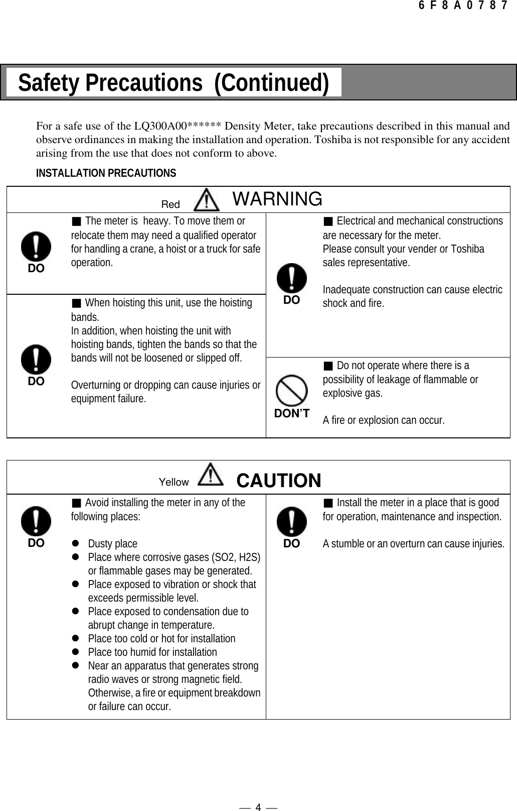
![ 3 6 F 8 A 0 7 8 7 Safety Precautions Important information is shown on the product itself and in the operation manual to protect users frombodily injuries and property damages, and to enable them to use the product safely and correctly.Please be sure to thoroughly understand the meanings of the following signs and symbols before readingthe sections that follow, and observe the instructions given herein. Keep the manual in a place you caneasily access to whenever you need it.[ Explanation of Signs]Sign Description WARNING Indicates a potentially hazardous situation which could result in death orserious injury, if you do not follow the instructions in this manual. CAUTION Indicates a potentially hazardous situation which may result in minor ormoderate injury, and/or equipment-only-damage, if you do not follow theinstruction in this manual.Note 1: Serious injury refers to cases of loss of eyesight, wounds, burns (high or low temperature),electric shock, broken bones, poisoning, etc., which leave after-effects or which requirehospitalization or a long period of outpatient treatment of cure.Note 2: Minor or moderate injury refers to cases of burns, electric shock, etc., which do not requirehospitalization or a long period of outpatient treatment for cure; equipment damage refers tocases of extensive damage involving damage to property or equipment.[ Explanation of the Symbols]Symbol DescriptionThis sign indicates PROHIBITION (Do not). The content of prohibition is shown by a pictureor words beside the symbol.This sign indicates MANDATORY ACTION (You are required to do). The content of actionis shown by a picture or words beside the symbol.This shape or symbol indicates WARNING. The content of WARNING is shown by a pictureor words beside the symbol.◆Color back : red, flame, picture and words : blackThis shape or symbol indicates CAUTION. The content of CAUTION is shown by a pictureor words beside the symbol.◆Color back : yellow, flame, picture and words : blackRedYellowRedYellow](https://usermanual.wiki/Toshiba/62372311/User-Guide-231580-Page-5.png)
![ 8 6 F 8 A 0 7 8 7 [NOTE] Sign In addition to the signs and symbols for safety precautions shown in the first several pages of themanual, the following sign is also used.♦[NOTE] SignWhen an explanation is made in the text regarding the Safety Precautions, the [NOTE] sign shownbelow appears in the left margin of a page. The [NOTE] gives you directions to follow in the followinginstances.•To use product correctly and effectively.•To prevent abnormal or degrading performance of the product.•To prevent faulty actions.•To store the product when you do not use the product for a long time.[Note]](https://usermanual.wiki/Toshiba/62372311/User-Guide-231580-Page-10.png)
![ 9 6 F 8 A 0 7 8 7 Important Notes on Use of The Insertion Type Density Meter LQ300A00****** Be sure to observe following instructions in order to maintain the original performance of the insertiontype density meter LQ300A00****** and safely use it over a long period of time.♦Toshiba is not held responsible for any fault or result caused by not observing the precautionsdescribed in this manual or by not observing the laws or regulations in installing or using theproduct.[NOTE] Do not install or store the product in the following places.Otherwise, meter performance can deteriorate and malfunction, fault, or breakage can occur.Place exposed to direct sunlightHot, humid placePlace exposed to severe vibration and shockPlace to be submerged under water except the liquid contacting area of the detectorPlace of corrosive atmosphere[NOTE] Use a separate wire for grounding the meter. Do not share the same grounding wire with otherdevices.Otherwise, malfunction, fault, or breakage can occur.[NOTE] Lay the output signal cable through their own conduit away from the AC power cable and othersources of noise.Noise can interrupt correct measurement.[NOTE] Perform periodic maintenance and inspection.A long period of reliable measurement requires periodic span calibration. (e.g. once every 3 months)Avoid using the density meter where fluid substances accumulate or entangle in the density meterdetector.[NOTE] Be careful not to let water or moisture into the applicator mount of the detector, converter, or cableends.Water or moisture can adversely affect performance and shorten parts service life.Close the covers and doors securely, and make the cable outlets airtight.[NOTE] Turn on the density meter only when the density meter is installed in a metal piping system.Make sure to turn off the power when installing or removing the density meter.Leakage of radio waves may cause interference to other equipment. [NOTE] Do not step on any part of the density meter (temperature detector mount, applicator (antenna)mount, converter for example) when you do piping work. Do not place any heavy object on it.Otherwise, deformation or fault can occur.](https://usermanual.wiki/Toshiba/62372311/User-Guide-231580-Page-11.png)
![ 10 6 F 8 A 0 7 8 7 Important Notes on Use of The Insertion Type Density Meter LQ300A00****** [NOTE] Do not use a transceiver, handy telephone, or other wireless device nearby.Such a device can adversely affect correct measurement. In the event one must be used, observe thefollowing precautions.(1) When using a transceiver, make sure that its output power is 5W or less.(2) When using a transceiver or a handy telephone, keep the converter and signal cable at least50cm away from the antenna.(3) Do not use a transceiver or a portable telephone nearby while the density meter is in onlineoperation. This is important to protect if from being affected by a sudden output power change.(4) Do not install the fixed antenna of a wireless device in the area around the converter and signalcable.[NOTE] Use a fuse of the specified rating.A fuse other than that specified can cause density meter malfunction or breakage.[NOTE] Do not modify or disassemble the density meter unnecessarily. Do not use parts other than specified.Failure can cause malfunction and density meter fault.[NOTE] When moving the meter elsewhere for installation, be careful not to drop, hit, or subject to strongshock.Otherwise, the density meter may be broken, resulting in malfunction or fault.[NOTE] Before returning your density meter to Toshiba for repair, etc., make sure to inform us about themeasured matter remaining in the density meter pipe, including whether it is dangerous or not totouch the material and then clean the meter so that no measured matter remains in its pipe.Disposal[NOTE] When disposing of this density meter, obey the rules and regulations of the local government.[FCC notice]This equipment has been tested and found to comply with the limits for a field disturbance sensor, pursuant to Part 15of the FCC rules. These limits are designed to provide reasonable protection against harmful interference in a residentialinstallation. This equipment generates, uses and can radiate radio frequency energy and, if not installed and used inaccordance with the instructions, it may cause harmful interference to radio communications. However, there is noguarantee that interference will not occur in a particular installation. If this equipment does cause harmful interference toradio or television reception, which can be determined by turning the equipment off and on, the user is encouraged to tryto correct the interference by one or more of the following measures.• Reorient the receiving antenna.• Increase the separation between the equipment and receiver.• Connect the equipment into an outlet on a circuit different fr6m' that to which the receiver is connected.• Consult the dealer or an experienced radio,'1'V technician for help.WARNING: This equipment has been certified to comply with the limits for a field disturbance sensor, pursuant toSubpart C of part 15 FCC rules. Except AC power cable, shielded cables must be used between the external devices andthe terminals of the converter of the equipment.Changes or modifications made to this equipment, not expressly approved by Toshiba or parties authorized by Toshibacould void the user's authority to operate the equipment.](https://usermanual.wiki/Toshiba/62372311/User-Guide-231580-Page-12.png)
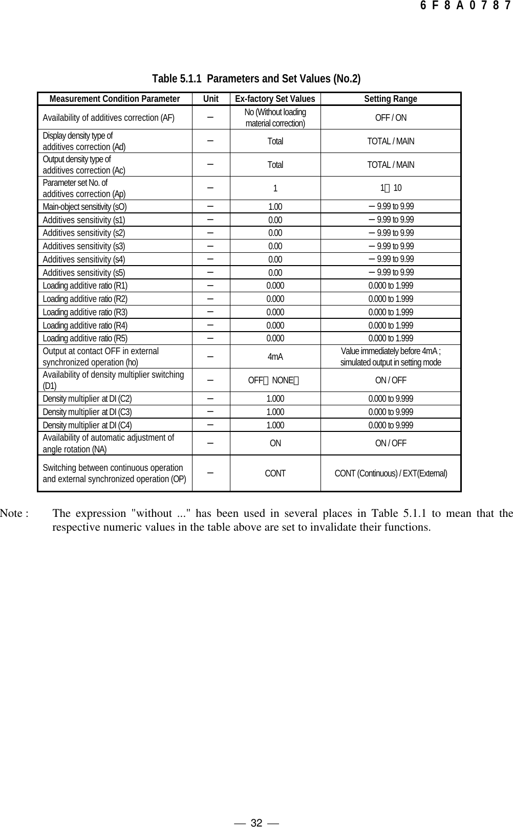
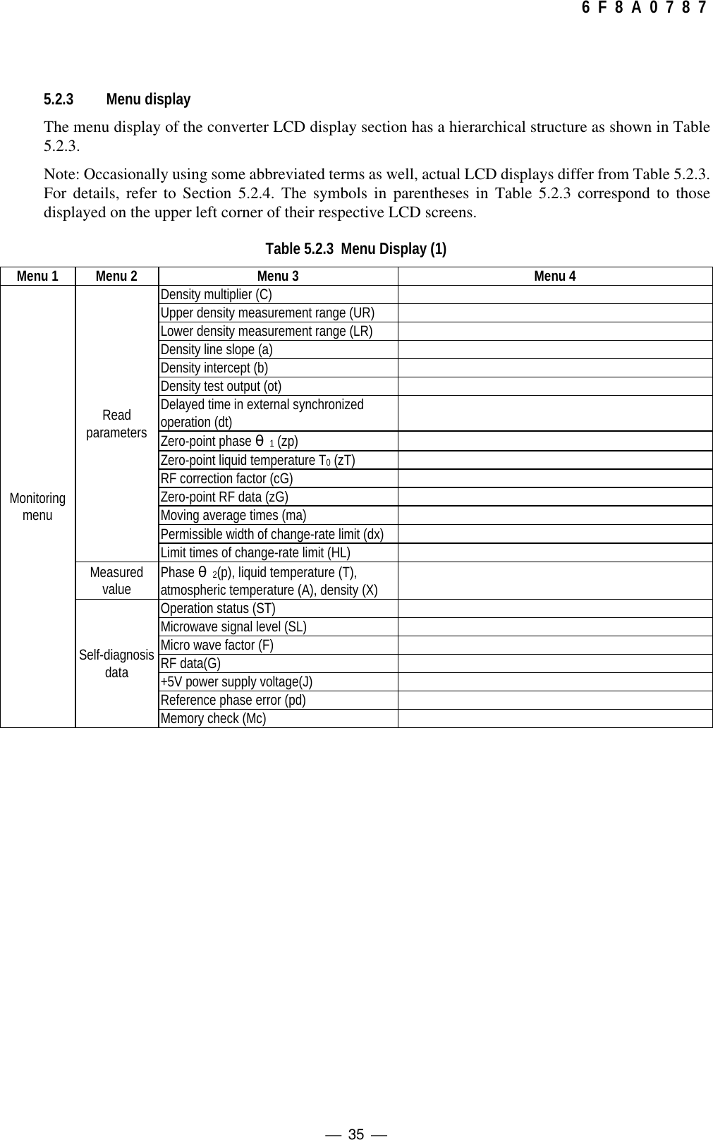
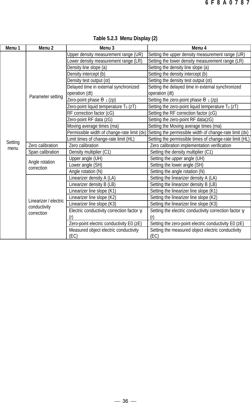
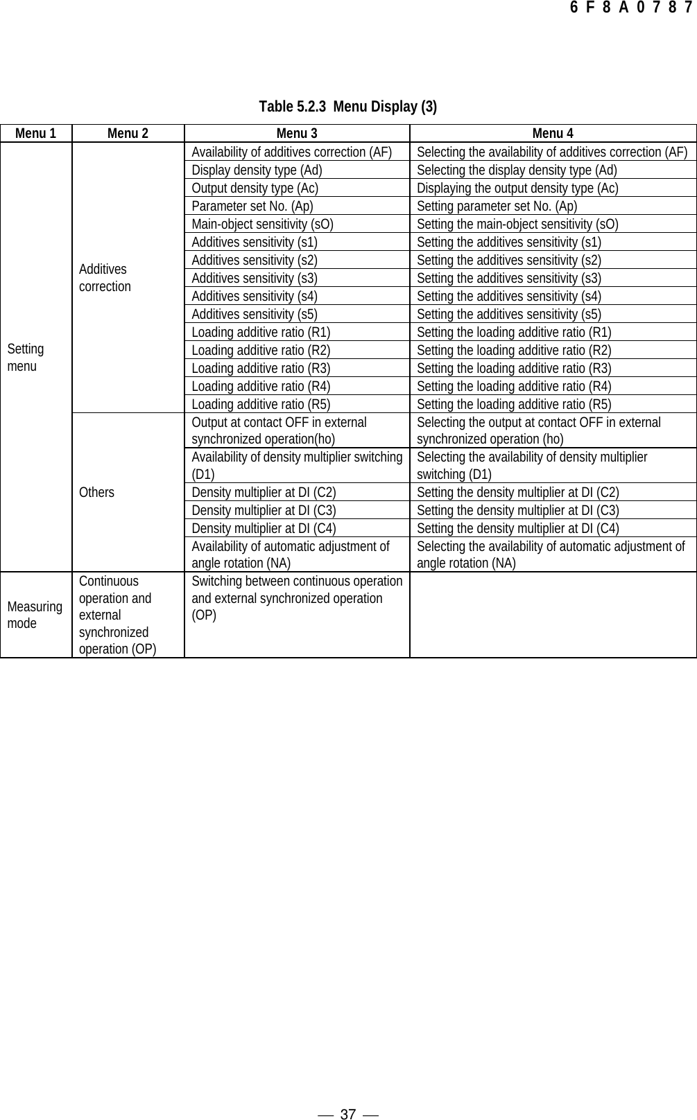
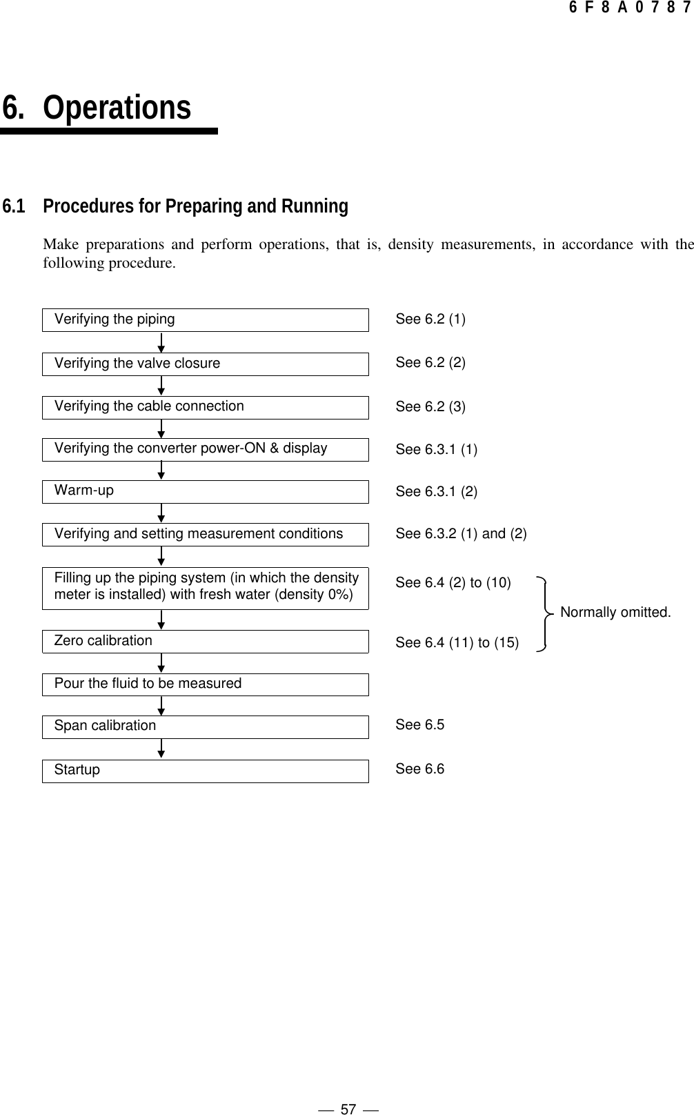
![ 11 6 F 8 A 0 7 8 7 Contents Safety Precautions................................................................................................................................................................................3[NOTE] Sign ...........................................................................................................................................................................................8Important Notes on Use of The Insertion Type Density Meter LQ300A00******..............................................................................91OVERVIEW.....................................................................................................................................................................................141.1 Principle of Measurement....................................................................................................................................................141.2 Features...............................................................................................................................................................................152UNPACKING...................................................................................................................................................................................162.1 Standard Components.........................................................................................................................................................162.2 Standard Accessories..........................................................................................................................................................163INSTALLATION..............................................................................................................................................................................173.1 Precautions for Installation...................................................................................................................................................173.2 Installation Location.............................................................................................................................................................193.3 Installation and Piping..........................................................................................................................................................213.4 Precautions for Wiring..........................................................................................................................................................253.5 Wiring...................................................................................................................................................................................264. Part Names and Functions...........................................................................................................................................................284.1 Detector................................................................................................................................................................................284.2 Conveter...............................................................................................................................................................................295. Operation Procedure.....................................................................................................................................................................315.1 Parameters and Set Values.................................................................................................................................................315.2 Menus and operations..........................................................................................................................................................335.2.1 main menu...................................................................................................................................................................335.2.2 Setting keys.................................................................................................................................................................345.2.3 Menu display...............................................................................................................................................................355.2.4 Monitoring menu display and operating procedures...................................................................................................385.2.5 Setting menu display and operating procedures....................................................................................................395.2.6 Measuring mode display and operating procedures...................................................................................................405.2.7 Reading of parameters display and operating procedures..........................................................................................405.2.8 Measured values display and operating procedures...................................................................................................445.2.9 Self-diagnosis data display operating procedures.......................................................................................................445.2.10 Parameter setting display and operating procedures..................................................................................................465.2.11 Zero calibration display and operating procedures.....................................................................................................495.2.12 Span calibration display and operating procedures ....................................................................................................495.2.13 Phase angle rotation correction display and operating procedures ............................................................................505.2.14 Linearize/conductity correction display and operating procedures..............................................................................515.2.15 Additives correction display and operating procedures...............................................................................................535.2.16 Other menus display and operating procedures.........................................................................................................566. Operations .....................................................................................................................................................................................576.1 Procedures for Preparing and Running................................................................................................................................576.2 Preparations before Turning on Power................................................................................................................................586.3 Power on and Preparations for Measuring...........................................................................................................................586.3.1 Turning power on........................................................................................................................................................58](https://usermanual.wiki/Toshiba/62372311/User-Guide-231580-Page-13.png)

![ 18 6 F 8 A 0 7 8 7Hoisting the Density Meter Before InstallationMake sure to hoist the density meter using the hoisting bands.Hoisting it with incomplete position or condition can cause a fall or damage to the density meter.When you move or install the Insertion Type Density Meter, make sure to hoist the density meterusing the hoisting bands. In addition, care should be taken to put the cushioning material between thehoisting band and the converter case. If the hoisting band touches the converter case directly it maycause a scratch on the converter front panel.Main unit mass: approx. 20 kgRecommended hoisting bands: made of cloth, applicable band size 25 mmNote: This unit is heavy. To move the unit or relocate it needs a qualified operator for handling a handtruck, crane, hoist or other. In addition, when hoisting the unit with hoisting bands, tighten thebands so that the bands will not be loosened or slipped off.吊り上げ方向吊りベルト装着位置重心位置[NOTE]吊り上げ方向吊りベルト装着位置重心位置Hoisting directionHoisting position with bandCenter of gravity positionFig. 3.1.1 Hoisting with Hoisting Bands (1) Fig. 3.1.1 Hoisting with Hoisting Bands (2)Hoisting directionCenter ofgravity positionHoisting positionwith band](https://usermanual.wiki/Toshiba/62372311/User-Guide-231580-Page-20.png)
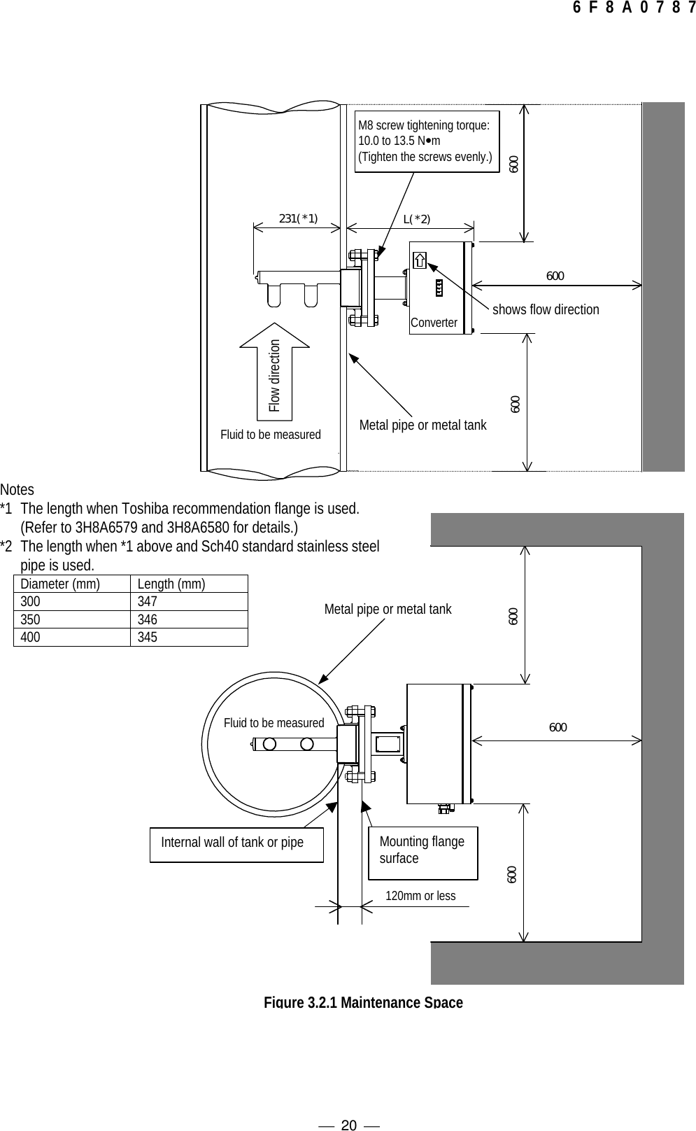
![ 19 6 F 8 A 0 7 8 73.2 Installation Location◆Determine an indoor installation place in accordance with the following instructions.(1) Choose a place that is free of vibrations and corrosive gasses, and has ample space formaintenance.(2) Secure maintenance space in front, rear and above the density meter. (Refer to fig. 3.2.1)(3) In the case of outdoor installation, provide covering against sun.(4) Do not install the meter in a place where there is a possibility of leakage of flammable orexplosive gas.(5) Use a strength pipe, connected at both upstream and downstream sides, to securelyinstall the detector main body, or provide a supporting structure for the detector mainbody. (Weight of this unit is shown in the external dimension list as attached.)(6) When the density meter is used in an application where the process fluid contains plentyof fur or fiber, these substances may accumulate or entangle in the density meter and thusperform the maintenance operation periodically (clean the insertion probe area).(7) The tank or pipe where this density meter is installed should be metal.(8) Install the density meter in a place where the density distribution is even. If the densitydistribution is not even, manual analysis data and the indication value of the density metermay not be the same.(9) Install this density meter in a piping system where bubbles are not found, and fluid doesnot empty itself, and also sedimentation and accumulation of materials does not occur.[NOTE]](https://usermanual.wiki/Toshiba/62372311/User-Guide-231580-Page-21.png)
![ 21 6 F 8 A 0 7 8 73.3 Installation and PipingInstalling the density meter is illustrated in Fig. 3.3.1 and Fig. 3.3.2, Fig.3.3.3, Fig.3.3.4.<Common Precautions>(1) Install the density meter in a place where the distribution of density is even.(2) Install the density meter in a location where the measured fluid flows in a tank or pipe in full and bubblesdo not stay. Insufficient fluid flowing or bubbles staying in the tube will cause measuring errors orindicated-value fluctuations.(3) Avoid installing the density meter where the material to be measured precipitates and accumulates atthe bottom of the tank or pipe.(4) Avoid installing the density meter in a tank or pipe where bubbles are mixed in the fluid to be measured.(5) The front side of the density meter's converter section is equipped with an LED density display section.When installing the meter, choose a location and direction in which this density display section will beeasily visible. However, if it is difficult to look straight at the density value display area as a result ofinstallation layout, we recommend you order an optional external display unit.(6) In the event that the tank or piping system (where the density meter is installed) may no longer be full ofthe fluid while the pump is shut down or the density distribution in the density meter may becomeuneven, make sure to take measurements only while the pump is operating by using the externalinterlock function.(7) Take necessary measures to prevent vibrations of the pump, etc. from travelling through the densitymeter.(8) Select the type and material of the gasket to use in the tank or pipe in accordance with the connectionmethod and the fluid material to measure.(9) Make sure that the surface for the O-ring face and O-ring itself are clean without dirt or dust beforestarting the installation work.(10) We recommend the following tightening torque for bolts and nuts when mounting the flange for thedensity meter. Tightening torque: 10.0 to 13.5 N•m for M8 bolts and nuts(11) Perform the periodical inspection to make sure that the thin and long materials such as fur, fiber orstrings are not entangled in the applicators (antenna), or there are no scratches or cracks.(12) Make sure that the applicator (antenna) is positioned more inside than the internal wall of the tank orpipe. The distance from the mounting flange face of the insertion probe area to the internal wall shouldbe 120 mm or less.<Piping Precautions>(13) We recommend the installation should be made to a vertical piping system. The density meter canoperate the same performance even in a horizontal installation but only a vertical installation is allowedfor item (14).(14) The installation should be made to a vertical piping system in the following cases:a) Bubbles may remain in the piping.b) The distribution of density in the piping may become uneven because the material to bemeasured precipitates or floats unusually due to slow flow rate etc.c) When main piping is enlarged and the density meter is installed to a larger piping system than themain piping.(15) We recommend that the converter section stay at the top when the density meter is installed to ahorizontal piping system because the maintenance is easy and its performance is assured.(16) We recommend that the density meter should be installed at a point as far away as possible from a portopen to atmosphere and the water pressure is required a little to prevent bubbles from entering in thefluid to be measured.[NOTE]](https://usermanual.wiki/Toshiba/62372311/User-Guide-231580-Page-23.png)
![ 22 6 F 8 A 0 7 8 7(17) On both the upstream and downstream sides of the density meter, install shutoff valves. Furthermore,between these valves and the density meter, install the sampling port, the zero water supply port, theair release port, the drain port with a shutoff valve attached respectively. In the event that the flow of thepipe line cannot be stopped, provide a bypass pipe halfway with a shutoff valve attached. Whenperforming zero point calibration, these are needed to discharge the measured matter out of the densitymeter through its drain port and fill up the meter with fresh water of zero density. (See Figures 3.3.2 and3.3.3.)(18) As to insertion orientation, install the density meter so that a pair of antennas face toward upstream.<Precautions when installing the density meter in a tank>(19) In a tank, install the density meter so that the applicators (antenna) are submerged 150 mm or moreunder water from the surface. If the depth of water is less than 150 mm or the applicators surface staysabove the water level in cases like a pump operation, use the external synch signal and measure thedensity only when the applicators surface remains more than 150 mm under water (see Figure 3.3.1.)(20) Install the density meter far from such places as near the agitator in a tank where bubble are generatedand density disturbances occur and this affects the density measurement.[NOTE]♦ Sampling valve: Used to extract fluids for manual analysis. Install this valve to the side of thepipe in the case of horizontal installation. It is recommended that a 1-inchball valve be installed to the side of the pipe.♦ Zero point water valve: Used to supply drinking water (density or consistency 0%) to the detectorpipe for zero point adjustment. Install this valve at the top of the pipe in thecase of horizontal installation. It is recommended that a 1-inch ball valve beinstalled in the top of the pipe and zero point water is supplied through thisinlet using a vinyl hose etc.If valve water pipe is connected to this valve, air cannot be extracted.Therefore, another valve (vent valve) is needed to extract air.♦ Vent valve: Used to vent process fluids to open air when performing zero adjustment.This helps the drinking water (density or consistency 0%) enter the detectorpipe easily. Install this valve in the top of the pipe in the case of horizontalinstallation.♦ Drain valve: Used to drain the fluids before supplying drinking water (density orconsistency 0%) to the detector pipe for zero adjustment. Install this valve atthe lowest point of the pipe. It is recommended that a 1-inch ball valve beinstalled at the lowest point of the pipe.Metal tank1500mm or more120mm or lessWater surfaceFluid to be measuredFigure 3.3.1 Precautions when installing the density meter in a tank](https://usermanual.wiki/Toshiba/62372311/User-Guide-231580-Page-24.png)
![ 23 6 F 8 A 0 7 8 7(1) Make sure that the surface for the O-ring face and O-ring itself are clean without dirt or dustbefore starting the installation work.(2) We recommend the following tightening torque for bolts and nuts when mounting the flange forthe density meter. Tightening torque: 10.0 to 13.5 N•m for M8 bolts and nuts[NOTE]Shutoff valveShutoff valveZero point water valveVent valveZero point water pipingDensity meterDrain valveDrain pipingBypass pipingShutoff valveDirection of flow upwardFig. 3.3.2 Meter mounted verticallyVent valve Zero point water valveShutoff valve Shutoff valveDensity meterDrain valveBypass pipingShutoff valveSampling valveFig. 3.3.3 Meter mounted Horizontally (looking from above)](https://usermanual.wiki/Toshiba/62372311/User-Guide-231580-Page-25.png)
![ 24 6 F 8 A 0 7 8 7(1) When you install the density meter, see 3.3.4 Precautions When Installing the Density Meter.(2) Install the density meter in a metal piping system.[NOTE] 589 231 When installing or removing the densitymeter, insert or remove the applicatormount section with its backside along themounting flange.Extra care should be taken not to let theapplicators (antenna) hit against the flangeor the internal wall.Make sure to mount the density meterso that the applicators (antenna) faceupstream and in parallel with thedirection of the flow.M8 screw tightening torque:10.0 to 13.5N•m(Tighten the screws evenly.)Flow directionFluid to be measuredshows flow directionDensity value displaySection A ConverterMake sure that the O-ring groove and O-ring itself are clean without dirt, dust orcracks before installing the density meter.Metal pipe or metal tank (56.6) 1.5 A A 3.2 Section A expandedFlange standard: JIS10KDiameter 100mmSch20Refer to 3H8A6579 and 3H8A6580 for details.Deviation from piping system inperpendicular direction: ±1.5° or lessSurface roughness: Ra3.2 minimumDeviation of flange hole positions with respect tothe piping axial direction: ±2° or lessFig 3.3.4 Installation Precaution](https://usermanual.wiki/Toshiba/62372311/User-Guide-231580-Page-26.png)
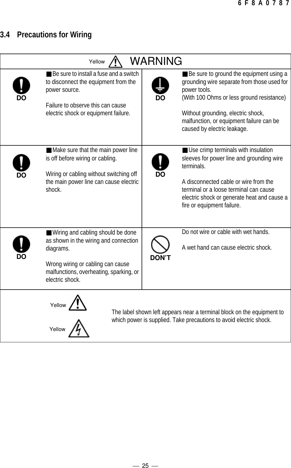
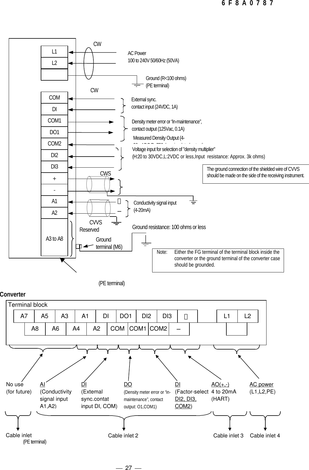
 Provide a switch and a fuse to separate this unit from the mains power for ease of maintenance.Power requirement of this unit is 50VA.(2) Ground the LQ300A00****** with 100 Ohms or less ground resistance. Do not use a common groundshared by other power equipment. The demands of the meter are 50VAs.(3) Use a sheathed cable (CVV) with 2mm2 cross-sectional area for AC power cable and make sure thevoltage drop across the cable is less than 2 V. And use a M4 sized solderless contact for connectioncable with terminal.(4) The cables should be free from vibration or sway. The cables should be placed in thick-walled steelconduits.(5) Wire the LQ300A00****** output in conduit separated from those of AC power cable, control signals,alarm signal or other cables which could become the source of noise.(6) Use a 2-wire shielded sheathed cable (CVVS) to wire the LQ300A00****** output (4 - 20mAdc). Andground the shielded cable on the receiving instrument side. For performing the conductivitycompensation, use a 2-wire shielded sheathed cable (CVVS) to wire the LQ300A00****** conductivitysignal input (4-20mA). And ground the shielded cable on the receiving instrument side.(7) As the cable port is made air-tight using a packing, tighten the cable gland securely when all thewiring is completed. If the diameter of the cable is smaller than the inside diameter of the packing,enlarge the cable diameter to the same size as the packing by wrapping valves around the cable. Itssuitable diameter is 11mm.(8) Tighten the terminal screws securely. Appropriated torque to tighten the screws is 1.2 N・m .(9) Do not turn on the power of the density meter when the applicators (antenna) are taken out of thepiping system. Leakage of radio waves may cause interference to external equipment.](https://usermanual.wiki/Toshiba/62372311/User-Guide-231580-Page-28.png)
![ 29 6 F 8 A 0 7 8 74.2 ConveterFigure 4.2 shows the converter cover (5 in Fig. 4.1) with its door open.Fig 4.2 Converter(10) Density indicator(4 in Fig 4.1)(7) Setting keys(6) LCD display(4) [MEASURE]indicator(5) [ALARM]indicator(11) Terminals forcommunication(3) [POWER] indicator(2) FUSE1A(M)250V(1) [POWER] switch(8) Terminal block(12) Ground terminal(9) Cable glands](https://usermanual.wiki/Toshiba/62372311/User-Guide-231580-Page-31.png)
![ 30 6 F 8 A 0 7 8 7(1) [POWER] switchThe power switch for the density meter.(2) Fuse1A(M), 250V glass tube fuse is inside.(3) [POWER] Indicator (Green LED)Green LED lights when AC power turns on by the power switch.(4) [MEASURE] Indicator (Green LED)The indicator lights when measuring, and turns off when setting and when measuring stops atexternally synchronized operation.(5) [ALARM] Indicator (Red LED)Lights on error signal from the meter.(6) LCD indicatorDisplays measured values, set values and self-diagnosis data, etc. Being an indicator of 20characters by 4 lines, it displays numerical values, alphanumeric characters and symbols inaccordance with needs.(7) Setting keysThese keys are used for switching between display contents of the LCD indicator or settingvarious set values. They include the [ESC] key, the [→] key, the [UP] key, [DN] key and the[SET] key.(8) Terminal blockRefers to the terminal block connecting cables for external connection.(9) Cable glandsFour cable glands are available for introducing cables for external connection, such as powersupplies and output signals.(10) Density (%TS) indicator (Red LED seven segments)Indicates the density of the measured matter in terms of %TS.(11) Terminals for communicationRemote control is made possible by connecting the leads of the hand-held terminal AF100 tothese terminals.(12) Ground terminalMake sure to ground this terminal to earth ground.](https://usermanual.wiki/Toshiba/62372311/User-Guide-231580-Page-32.png)
![ 33 6 F 8 A 0 7 8 75.2 Menus and operationsOperations should be done with five keys for setting, in combination with the LCD display. This sectionshows menus and operations.5.2.1 main menuMain menu is composed of three basic menus shown below. Table 5.2.1 shows the functions of eachmenu and performances when selected.<main menu>Table 5.2.1. Functions and performances of main menu1 : MONITORINGMENU 2 : SETTINGMENU 3 : MEASURINGMODEFunctionsReading of each measuringconditions (parameters),measured values, and self-diagnosis dataChanging of eachmeasuring conditions(parameters), zerocalibration and spancalibrationMode selection from among twomeasuring modes (operation modes)of the normal continuous operationand the externally synchronizedoperationMeasured density output(4 to 20mA)Measured densitycontinuous output Density Test output Measured density continuous outputDensity display Measured density value Density Test output Measured density valve[Measure] indicator On Off OnNote: In the Setting menu, when “Zero calibration” or “Span calibration” is executed, LED densitydisplay indicates the Measured Density value and not the preset Density Test output becausethis makes it easy to quickly compare the density measured output before and after the zero orspan calibration. On the other hand, the Measured Density Current output continuous to outputthe Density Test output in every Setting menu including Zero calibration and Span calibration.1 : MONITORING MENU2 : SETTING MENU3 : MEASURING MODE](https://usermanual.wiki/Toshiba/62372311/User-Guide-231580-Page-35.png)
![ 34 6 F 8 A 0 7 8 75.2.2 Setting keysFive setting keys are available. The basic methods for using them are described in Table 5.2.2. Forspecification information, please refer to their respective operating procedures.Table 5.2.2 Basic Methods for Using Operation KeysSettingKeyNotation inOperationManual Basic UseReturns to the menu screen that is one level higher.ESC [ESC] On the set value change screen, use this key to clear the setup change before returningto the previous screen.On the menu list screen, use this key to move the cursor under the menu number to thelocation of the next number.In the state of setting numerical values, press this key each time the cursor has to beshifted rightwards by a digit's worth. If the cursor is located rightmost, the cursor isshifted to the leftmost digit.[→]In the event of entering the setting menu, press the [SET] key to display the messagesaying that the output will be switched to the simulated value. After making sure that noproblem is present, press the [→] key to enter the setting menu. This procedure is takenfor the purpose of preventing the output from being switched to the simulated value as aresult of mistakenly pressing the [SET] key twice in a row.On the menu screen, use this key to switch to the next menu screen.In the state of setting numerical values, use this key to move up the numeric value of thedigit where the cursor is located. Each time the key is pressed, the numeric valuechanges incrementally, as following; "0", "1", "2", ・・・・, "9", "-"(minus symbol),"."(decimal point), "0", "1", "2", ・・・・.Note: If the numerical value does not belong to the leftmost digit, "-" (minus symbol) willnot appear after 9. UP [UP]In the event of selecting an item from multiple items (such as ON/OFF), the cursor (of theselected item) is switched each time this key is pressed.On the menu screen, use this key to switch to the previous menu screen.In the state of setting numerical values, use this key to move down the numerical value ofthe digit where the cursor is located. Each time the key is pressed, the numerical valuechanges detrimentally , as following; "0", "."(decimal point), "-"(minus symbol), "9","8", ・・・・ "1", "0".Note: If the numerical value does not belong to the leftmost digit, "-" (minus symbol) willnot appear after "."(decimal point). DN [DN]In the event of selecting an item from multiple items (such as ON/OFF), the cursor (of theselected item) is switched each time this key is pressed. SET [SET] Use this key to select the menu number where the cursor is located or confirm the setvalue.](https://usermanual.wiki/Toshiba/62372311/User-Guide-231580-Page-36.png)
![ 38 6 F 8 A 0 7 8 75.2.4 Monitoring menu display and operating procedures1 :READ PARAMETERS2 :MEASURED VALUES3 :SELF-DIAGNOSIS1 :MONITORING MENU2 :SETTING MENU3 :MEASURING MODEMenus of[1 : READ PARAMETERS]Data display of[2 : MEASURED VALUES]Data display of[3 : SELF-DIAGNOSIS]Move the cursor to the menunumber with [→] key, andpress [SET] key.Move the cursor to "1" with [→] key, andpress [SET] key.[ESC](PreviousMenu)[ESC](Previous Menu)Note:In actual display, the cursor isblinking.](https://usermanual.wiki/Toshiba/62372311/User-Guide-231580-Page-40.png)
![ 39 6 F 8 A 0 7 8 75.2.5 Setting menu display and operating proceduresWhen [2: SETTING MENU] is selected, the densityoutput signal and the density display are hold in thesimulated values that have been set. This warningscreen will appear once before getting into [2: SETTINGMENU]. After making sure that there is no problem, pressthe [→] key to get into [2: SETTING MENU].To get into [2: SETTING MENU], it is necessary to furtherenter the password "8000". In the initial condition, the cursoris on the forth digit. Therefore, press [DN] key 4 times to set to"8" and press the [SET] key to get into [2: SETTING MENU].An incorrect password will cause the following message toappear. Return to the screen at left by pressing any key andthen enter the correct password once again.1 :MONITORING MENU2 : SETTING MENU3 : MEASURING MODEInput passwordPASSWORD :0000[SET]SET,[ESC]CANCELPASSWORD ERRORPUSH ANY KEY.9:LINEARIZ/CNDUCTVTY10:ADDITIVES CORRECT11:OTHERSMove the cursor to the menu number with[→] key, and press [SET] key.Press the [→] key to get into [2: SETTING MENU].[ESC](PreviousMenu)1 :READ PARAMETERS2 :MEASURED VALUES3 :SELF-DIAGNOSISMove the cursor to "2" with [→] key, and press [SET] key.Test output will bevalid.[→] : CONTINUE[ESC]: CANCEL5:SET PARAMETERS6:ZERO CALIBRATION7:SPAN CALIBRATION8:ANGLE ROTATION[ESC](PreviousMenu)[ESC](PreviousMenu)[ESC](PreviousMenu)[ESC](PreviousMenu)[DN][UP][DN][UP]](https://usermanual.wiki/Toshiba/62372311/User-Guide-231580-Page-41.png)
![ 40 6 F 8 A 0 7 8 75.2.6 Measuring mode display and operating procedures5.2.7 Reading of parameters display and operating proceduresOP:MEASURING MODEDATA:CONT[SET] CHANGE [ESC] RETURN OP:MEASURING MODERANGE :CONT/EXTDATA :CONT[SET] SET,[ESC]CANCEL1 :MONITORING MENU2 :SETTING MENU3 :MEASURING MODEMove the cursor to "3" with [→] key, and press [SET] key.Press the SET key to set.Press the SET key to confirm.Press the ESC key to cancel.Move the cursor to "1" with [→] key, and press [SET] key,and select [1 : READ PARAMETERS]UR:UPPER RANGEDATA:3.0[ESC] RETURNLR:LOWER RANGEDATA:0.0[ESC] RETURN[DN][UP][DN][UP][UP]1 :READ PARAMETERS2 :MEASURED VALUES3 :SELF-DIAGNOSISC:DENSITY MULTIPLIERDATA:1.000(C1)[ESC] RETURNEach time the [UP] or [DN] key is pressed, CONT/EXT aremutually alternated thus making it possible to select an operationmode. Select "CONT" for normal continuous operations; select"EXT" for external synchronized operations. For details on theexternal synchronized operation, refer to Section 6.7.The set value of the density multiplier C, which is used for densitycalculation, can be verified. If C2, C3 or C4 is displayed in theparentheses, it indicates that the density multiplier switched to by theexternal voltage signal (DI) is selected.The set value of the upper density measurement range (thedensity whose current output is 20mA) can be verified.The set value of the lower density measurement range (thedensity whose current output is 4mA) can be verified.[ESC](PreviousMenu)[ESC](PreviousMenu)[ESC](PreviousMenu)[ESC](PreviousMenu)](https://usermanual.wiki/Toshiba/62372311/User-Guide-231580-Page-42.png)
![ 41 6 F 8 A 0 7 8 7a:DENSITY LINE SLOPEDATA:0.0840[ESC] RETURNb:DENSITY INTERCEPTDATA:0.0[ESC] RETURNot:DENSTY TEST OUTDATA:1.5 [ESC] RETURNdt:DELAYED SYNC.TIMEDATA:0.5[ESC] RETURN[DN][UP][DN][DN][UP][DN][UP]The set value of "density line slope" of thearithmetic expression for calculating the densityfrom the phase measurement data, etc. can beverified. Normally “0.084” is displayed here.The set value of "density intercept" of the arithmeticexpression for calculating the density from thephase measurement data, etc. can be verified.Normally, this is set to zero.Upon getting into [2: SETTING MENU], the currentoutput and the LED density display are switched tosimulated values. In this screen, the set value of thesimulated value (unit: %TS) can be verified.In external synchronized operations, the set valueof the delayed time (unit: minute) from when theexternal contact input is turned ON until themeasurement starts can be verified. For details,refer to Section 6.7.The phase at the time of zero calibration can beverified.[ESC](PreviousMenu)[ESC](PreviousMenu)[ESC](PreviousMenu)[ESC](PreviousMenu)[ESC](PreviousMenu)[DN][UP]zp:ZERO POINT PHASEDATA:80.00[ESC] RETURNNote : The item which is enclosed dot line is not displayed for Density meters with itsROM version 1.07 or later.[UP]](https://usermanual.wiki/Toshiba/62372311/User-Guide-231580-Page-43.png)
![ 42 6 F 8 A 0 7 8 7[DN][DN][UP]The liquid temperature at the time of zero calibration can beverified.The set value of the RF correction factor used for densitycalculation can be verified. Before shipment, this value isalready set in accordance with the product's characteristics inthe shipping test. If you change this value, it will affect theperformance; therefore, normally, do not change it.The RF data at the time of zero calibration can be verified.The set value of the moving average times can be verified.The variation width (%TS) permitted in the change-rate limitfunction can be verified.[ESC](PreviousMenu)[ESC](PreviousMenu)[ESC](PreviousMenu)[ESC](PreviousMenu)[ESC](PreviousMenu)[ESC](PreviousMenu)[DN][UP][DN][UP][DN][UP][DN][UP]cG:RF COEF.DATA:0.00[ESC] RETURN zG:ZERO RF DATADATA:50.00[ESC] RETURNma:AVERAGING TIMESDATA:1[ESC] RETURN zT:ZERO LIQUID TEMP.DATA:25.00[ESC] RETURNdx: CHANGE-RATE LIMITDATA:0.00[ESC] RETURNHL:LIMIT TIMESDATA:0[ESC] RETURNThe times permitted in the change-rate limit function can beverified.[UP]](https://usermanual.wiki/Toshiba/62372311/User-Guide-231580-Page-44.png)
C:DENSITY MULTIPLIERDATA:1.000[ESC] RETURN[DN]](https://usermanual.wiki/Toshiba/62372311/User-Guide-231580-Page-45.png)
![ 44 6 F 8 A 0 7 8 75.2.8 Measured values display and operating procedures5.2.9 Self-diagnosis data display operating proceduresp PHASE: 123.56 N=0T LIQ_TMP: 30.00 ℃A AT_TMP : 30.00 ℃*X DENSITY: 2.34 %TS:Move the cursor to "2" with [→] key, and press [SET] key toselect [ 2:MEASURED VALUES]1 :READ PARAMETERS2 :MEASURED VALUES3 :SELF-DIAGNOSISIt is possible to verify the measured phase value (andthe angle rotation N), the measured liquid temperaturevalue, the measured atmospheric temperature value, aswell as the density calculated based on them. [*] at theleft end of the bottom line will blink synchronously withthe data updating thus making it possible to verify thatthe data updating is definitely taking place.[ESC](PreviousMenu)[ESC](PreviousMenu)[ESC](PreviousMenu)[ESC](PreviousMenu)[DN][UP]SL:MICROWAVE SIG.LVLDATA :−53 [ESC] RETURNF:MICROWAVE COEF.DATA : 1910 [ESC] RETURNMove the cursor to "3" with [→] key,and press [SET] key to select [3:SELF-DIAGNOSIS][DN][UP]ST:STATUS :GOOD[ESC] RETURNWhether the phase measurement operation isnormally functioning or not can be verified.The micro wave receive signal level can beverified. Normally, the level is -45 to -75.The micro wave signal constant can be verified.Normally, the value is 1825 to 1975.1 :READ PARAMETERS2 :MEASURED VALUES3 :SELF-DIAGNOSIS[UP]](https://usermanual.wiki/Toshiba/62372311/User-Guide-231580-Page-46.png)
![ 45 6 F 8 A 0 7 8 7G:RF DATA.DATA : 40.00[ESC] RETURNJ:+5V POWER SUPPLYDATA :5.00[ESC] RETURNMc:MEMORY CHECK:GOOD EPROM :GOOD RAM :GOOD EEPROM :GOOD[ESC](PreviousMenu)[ESC](PreviousMenu)[ESC](PreviousMenu)[ESC](PreviousMenu)[ESC](PreviousMenu)ST:STATUS :GOOD [ESC] : RETURN [DN]The soundness of the phase measurement unitcan be verified.The soundness of various memory units can beverified.The converter's RF data (concerning the microwave phase measurement) can be verified.Normally, the value is 10 to 70.The voltage of the 5-volt power supply can bechecked.pd:REF PHASE DATA:0.0 [ESC] RETURN[DN][UP][DN][UP][DN][UP][DN][UP]](https://usermanual.wiki/Toshiba/62372311/User-Guide-231580-Page-47.png)
![ 46 6 F 8 A 0 7 8 75.2.10 Parameter setting display and operating procedures5:SET PARAMETERS6:ZERO CALIBRATION7:SPAN CALIBRATION8:ANGLE ROTATIONMove the cursor to "5" with [→] key, and press [SET] key to select[ 5:SET PARAMETERS]UR:UPPER RANGEDATA:3.0[SET] CHANGE [ESC] RETURN.UR:UPPER RANGERANGE :1.0-99.9 %TSDATA :[SET] SET,[ESC] CANCEL[SET](Set)[ESC](Cancel)[ESC](PreviousMenu)[SET](Fix)LR:LOWER RANGEDATA:0.0[SET] CHANGE [ESC] RETURNLR:LOWER RANGERANGE :0.0-99.5 %TSDATA :[SET] SET,[ESC] CANCEL[SET](Set)[SET](Fix)[ESC](Cancel)[ESC](PreviousMenu)The upper density measurement range (whosecurrent output is 20mA) is set.[DN][UP]a:DENSITY LINE SLOPEDATA:0.0840[SET] CHANGE [ESC] RETURNa:DENSITY LINE SLOPERANGE :−0.2000−0.2000DATA :[SET] SET,[ESC] CANCEL[SET](Set)[SET](Fix)[ESC](Cancel)[ESC](PreviousMenu)[DN][UP] The lower density measurement range (whosecurrent output is 4mA) is set.ot:DENSTY TEST OUT. DATA:3.0[SET] CHANGE [ESC] RETURNot:DENSTY TEST OUT.RANGE :0.0-99.9 %TSDATA :[SET] SET,[ESC] CANCEL[SET](Set)[SET](Fix)[ESC](Cancel)[DN][UP]The "density intercept" of the arithmetic expression for calculating thedensity from the phase measurement data, etc. is set. In the event thatthe zero point is out of position, it is corrected through zero calibration; it isalso possible to shift the zero point by changing this coefficient. Normally,set the value to zero.[ESC](PreviousMenu)b:DENSITY INTERCEPTDATA:0.00[SET] CHANGE [ESC] RETURNb:DENSITY INTERCEPTRANGE :−99.99−99.99DATA :[SET] SET,[ESC] CANCEL[SET](Set)[SET](Fix)[ESC](Cancel)The "density line slope" of the arithmetic expression for calculating thedensity from the phase measurement data, etc. is set. However,normally do not change settings here.[DN][UP]When [2: SETTING MENU] is selected, the density output signaland the density display are hold in the simulated values that havebeen set. In this screen, the simulated values are set in terms of "%TS".[ESC](PreviousMenu)[DN][UP]](https://usermanual.wiki/Toshiba/62372311/User-Guide-231580-Page-48.png)
![ 47 6 F 8 A 0 7 8 7dt:DELAYED SYNC.TIMEDATA:0.5 [SET] CHANGE [ESC] RETURNdt:DELAYED SYNC.TIMERANGE :0.1-99.9 minDATA :[SET] SET,[ESC] CANCELIn external synchronized operations, the delayed time from when theexternal contact input is turned ON until the measurement starts isset. For details, refer to Section 6.7.[ESC](PreviousMenu)[SET](Set)[SET](Fix)[ESC](Cancel)[DN]zp:ZERO POINT PHASEDATA:80.00[SET] CHANGE [ESC] RETURNzp:ZERO POINT PHASERANGE :0.00-359.99DATA :[SET] SET,[ESC] CANCELThe zero-point phase can be set in this menu through manual input.Normally, the zero-point phase is automatically set whenimplementing the zero calibration.[DN][UP][ESC](PreviousMenu)[SET](Set)[SET](Fix)[ESC](Cancel)zT:ZERO LIQUID TEMP.DATA:25.00[SET] CHANGE [ESC] RETURNzT:ZERO LIQUID TEMP.RANGE :0.00-100.00 ゚CDATA :[SET] SET,[ESC] CANCELThe zero-point liquid temperature can be set in this menu throughmanual input. Normally, the zero-point liquid temperature isautomatically set when implementing the zero calibration.[DN][UP][SET](Set)[SET](Fix)[ESC](Cancel)[ESC](PreviousMenu)[DN][UP]The RF correction factor used for density calculation is set. Beforeshipment, this value is already set in accordance with the product'scharacteristics in the shipping test. If you change this value, it will affectthe performance; therefore, normally, do not change it.cG:RF COEF.DATA: 0.00[SET] CHANGE [ESC] RETURNcG:RF COEF.RANGE : -9.99-9.99DATA:[SET] SET,[ESC] CANCEL[ESC](PreviousMenu)[SET](Set)[SET](Fix)[ESC](Cancel)[UP]](https://usermanual.wiki/Toshiba/62372311/User-Guide-231580-Page-49.png)
![ 48 6 F 8 A 0 7 8 7zG:ZERO RF DATADATA: 50.00[SET] CHANGE [ESC] RETURNzG:ZERO RF DATARANGE :0.00-100.00 ゚CDATA:[SET] SET,[ESC] CANCELThe zero-point RF data can be set in this menu through manualinput. Normally, the zero-point RF constant is automatically set whenimplementing the zero calibration.[DN][ESC](PreviousMenu)[SET](Set)[SET](Fix)[ESC](Cancel)ma:AVERAGING TIMES DATA:1[SET] CHANGE [ESC] RETURNma:AVERAGING TIMESRANGE : 1-99DATA :[SET] SET,[ESC] CANCELThe moving average times are set. If the output averaged for densitycontrol, etc. is needed, the value from 5 to about 10 is set.[ESC](PreviousMenu)[SET](Set)[SET](Fix)[ESC](Cancel)dx:CHANGE RATE LIMITDATA:0.00[SET] CHANGE [ESC] RETURNdx:CHANGE RATE LIMITRANGE :0.00-9.99DATA:[SET] SET,[ESC] CANCELIf there is a signal of sharp variation, the change-rate limit functionexcludes this signal to restrict a sudden output variation. In thismenu, the permissible variation width is set in terms of "%TS".[DN][UP][DN][UP][ESC](PreviousMenu)[SET](Set)[SET](Fix)[ESC](Cancel)HL:LIMIT TIMESDATA: 0[SET] CHANGE [ESC] RETURNHL:LIMIT TIMESRANGE :0-99 DATA:[SET] SET,[ESC] CANCELThe limit times in the change-rate limit function are set. If the variationwidth exceeds dx(%TS) that was set in the previous menu, the signal isexcluded for up to the HL times that are set in this menu. At HL=0, thechange-rate limit function does not work.[SET](Set)[SET](Fix)[ESC](Cancel)[DN][UP][ESC](PreviousMenu)[DN][UP]UR:UPPER RANGEDATA:3.0[SET] CHANGE [ESC] RETURN[ESC](PreviousMenu)VALUE OUT OF RANGEUR:UPPER RANGEPRESS ANY KEY TORETURNFor all menus, when data outside the allowed range isinput, the error message is displayed, and the wrongdata is refused. Press any key to return, and inputadequate data.[NOTE]:](https://usermanual.wiki/Toshiba/62372311/User-Guide-231580-Page-50.png)
![ 49 6 F 8 A 0 7 8 75.2.11 Zero calibration display and operating procedures5.2.12 Span calibration display and operating proceduresMove the cursor to "7" with [→] key, and press [SET] key to select [7:SPAN CALIBRATION]5:SET PARAMETERS6:ZERO CALIBRATION7:SPAN CALIBRATION8:ANGLE ROTATIONC1:DensityMultiplierDATA:1.000[SET] CHANGE [ESC] RETURN[ESC](PreviousMenu)C1:DensityMultiplierRANGE :0.000-9.999DATA :[SET] SET,[ESC]CANCEL[SET](Set)[SET](Fix)[ESC](Cancel)The density multiplier C1 should be set to thesuitable value so that the measured density value iscorresponding to the manual analysis value. Fordetails, refer to Section 6.5.Move the cursor to "6" with [→] key, and press [SET] key to select [6:ZERO CALIBRATION]5:SET PARAMETERS6:ZERO CALIBRATION7:SPAN CALIBRATION8:ANGLE ROTATIONzp PHASE :81.23 ゜ N=0zT TEMP. :26.55 °CzA TEMP. :26.55 °C*X DENSITY : 0.05 %TSZERO POINT CALIBRATIONHAS BEEN COMPLETED[SET](Set)New data displayed[ESC](PreviousMenu)Press the [SET] key for zero calibration. In zero calibration, thephase, the liquid temperature, the atmospheric temperature, andRF data of zero point will be replaced with the present measuredvalues. And also, angle rotation "N" will be set to zero.Note:The display will return to the left display automatically afterapproximately one second.](https://usermanual.wiki/Toshiba/62372311/User-Guide-231580-Page-51.png)
![ 50 6 F 8 A 0 7 8 75.2.13 Phase angle rotation correction display and operating proceduresMove the cursor to "8" with [→] key, and press [SET] keyto select [8:ANGLE ROTATION]5:SET PARAMETERS6:ZERO CALIBRATION7:SPAN CALIBRATION8:ANGLE ROTATIONUH:UPPER ANGLEDATA : 20[SET] CHANGE [ESC] RETURNUH:UPPER ANGLERANGE :240-360 ゚DATA :[SET] SET,[ESC] CANCEL[SET](Set)[SET](Fix)[ESC](Cancel)Before shipping, this value is set to 260 degrees. Changingthe setting may result in damaging the otherwise normaloperation. Therefore, normally, do not change the setting.[DN][UP]SH:LOWER ANGLEDATA :100[SET] CHANGE [ESC] RETURNSH:LOWER ANGLERANGE :0-120 ゚ DATA :[SET] SET,[ESC] CANCELBefore shipping, this value is set to 100 degrees. Changingthe setting may result in damaging the otherwise normaloperation. Therefore, normally, do not change the setting.[ESC](PreviousMenu)[ESC](PreviousMenu)[SET](Set)[SET](Fix)[ESC](Cancel)N:ROTATION DATA:0[SET] CHANGE [ESC] RETURNN:ROTATIONRANGE :−10 - 10DATA :[SET] SET,[ESC] CANCELUH:UPPER ANGLEDATA :260[SET] CHANGE [ESC] RETURNNormally, the angle rotation N is automatically computed;therefore, it is unnecessary to change the setting throughmanual input. However, there are some cases of high densitymeasurements which require settings through manual input.[ESC](PreviousMenu)[DN][UP][SET](Set)[SET](Fix)[ESC](Cancel)[DN][UP][ESC](PreviousMenu)](https://usermanual.wiki/Toshiba/62372311/User-Guide-231580-Page-52.png)
![ 51 6 F 8 A 0 7 8 75.2.14 Linearize/conductity correction display and operating proceduresMove the cursor to "9" with [→] key, and press [SET] key toselect [ 9:LINEARIZ/CNDUCTVTY]LA:DENSITY ADATA :0.60[SET] CHANGE [ESC] RETURNLA:DENSITY ARANGE :0.00-99.99DATA :[SET] SET,[ESC] CANCEL[SET](Set)[SET](Fix)[ESC](Cancel)9:LINEARIZ/CNDUCTVTY10:ADDITIVES CORRECT11:OTHERS[ESC](PreviousMenu)In the event of three straight lines which closely analogouseach other, the density of the crossover point A of the 2nd and3rd lines is set.LB:DENSITY BDATA:1.00[SET] CHANGE [ESC] RETURNLB:DENSITY BRANGE :0.00-99.99DATA :[SET] SET,[ESC] CANCEL[DN][UP]In the event of three straight lines which closely analogouseach other, the density of the crossover point B of the 2nd and3rd lines is set.[ESC](PreviousMenu)[SET](Set)[SET](Fix)[ESC](Cancel)[DN][UP]K1:COEF.DATA:1.00[SET] CHANGE [ESC] RETURNK1:COEF.RANGE:0.00-9.99DATA :[SET] SET,[ESC] CANCELIn the event of three straight lines which closely analogouseach other, the inclination K1 of the 1st line is set.[SET](Set)[SET](Fix)[ESC](Cancel)[ESC](PreviousMenu)[DN][UP]K2:COEF. DATA:1.00[SET] CHANGE [ESC] RETURNK2:COEF.RANGE:0.00-9.99DATA :[SET] SET,[ESC] CANCELIn the event of three straight lines which closely analogouseach other, the inclination K2 of the 2nd line is set.[ESC](PreviousMenu)[SET](Set)[SET](Fix)[ESC](Cancel)K3:COEF. DATA:1.00[SET] CHANGE [ESC] RETURNK3:COEF.RANGE :0.00-9.99DATA :[SET] SET,[ESC] CANCELIn the event of three straight lines which closely analogouseach other, the inclination K2 of the 3rd line is set.[DN][UP][ESC](PreviousMenu)[SET](Set)[SET](Fix)[ESC](Cancel)[UP]](https://usermanual.wiki/Toshiba/62372311/User-Guide-231580-Page-53.png)
![ 52 6 F 8 A 0 7 8 7r:CNDUCTVTY. COEF.RANGE :10.00[SET] DATA[ESC] RETURNr:CNDUCTVTY. COEF.RANGE :0.00-99.99DATA :[SET] SET,[ESC] CANCEL[SET](Set)[SET](Fix)[ESC](Cancel)[DN][DN][UP][ESC](PreviousMenu) In the event of performing electric conductivity correction, thecorrection factor γ is set. At γ= 0.00, electric conductivitycorrection does not work.zE:CNDUCTVTY. /ZERODATA:3.00[SET] CHANGE [ESC] RETURNMANU/LINE SELECTIONRANGE :MANU/LINEDATA :(LINE)[SET] SET,[ESC] CANCEL[UP] and [DN] is used to switch between MANU/LINEto select the method for setting the zero-point electricconductivity. By selecting "LINE" and pressing [SET]in the zero-point state (see the screen above), theelectric conductivity signal of the zero point is read tobe automatically set as the zero-point electricconductivity.[ESC](PreviousMenu)[SET](Set)[SET]( Fix in "LINE mode")[ESC](Cancel)MANU/LINE SELECTIONRANGE :MANU/LINEDATA:(MANU)[SET] SET,[ESC] CANCEL[UP][DN]zE:CNDUCTVTY. /ZERORANGE :0.00-10.00DATA :[SET] SET,[ESC] CANCEL[ESC](Cancel)EC:CONDUCTIVITYDATA:1.23(LINE)[SET] CHANGE [ESC] RETURNMANU/LINE SELECTIONRANGE :MANU/LINEDATA:(LINE)[SET] SET,[ESC] CANCEL[SET](Set)[SET](Fix in"LINE mode")[ESC](Cancel)[ESC](PreviousMenu)MANU/LINE SELECTIONRANGE :MANU/LINEDATA:(MANU)[SET] SET,[ESC] CANCEL[DN][UP]or [DN]EC:CONDUCTIVITYRANGE :0.00-10.00DATA:[SET] SET,[ESC] CANCELLA:DENSITY ADATA :0.60[SET] CHANGE [ESC] RETURNBy selecting "MANU" (see the screen above) andthen pressing [SET], the electric conductivity of themeasured object is made settable as the fixed valuethrough manual input.After the zero-pointelectric conductivityis entered, [SET] isused to confirm thesetting in MANUmode.[ESC](Cancel)[ESC](PreviousMenu)Selecting MANU/LINE with [UP] or [DN], the settingmethod of electric conductivity correction can be chosen.When “LINE” is selected (above screen), and thenpressing [SET], the density measurement with continuousconductivity correction will be made using the conductivitysignal from the object to be measured.](https://usermanual.wiki/Toshiba/62372311/User-Guide-231580-Page-54.png)
![ 53 6 F 8 A 0 7 8 75.2.15 Additives correction display and operating proceduresMove the cursor to "10" with [→] key, and press [SET]key to select [10:ADDITIVES CORRECT ]AF:ADDITIVES COMP.DATA :ON[SET] CHANGE [ESC] RETURNAF:ADDITIVES COMP.RANGE :OFF/ONDATA:ON[SET] SET,[ESC] CANCEL9:LINEARIZ/CNDUCTVTY10:ADDITIVES CORRECT11:OTHERSEach time the [UP] or [DN] key is pressed, OFF/ON aremutually alternated thus making it possible to select theavailability of the additives correction function. If OFF isselected, the following screen will not appear.[SET](Set)[SET](Fix)[ESC](Cancel)[ESC](PreviousMenu)Ad:DISPLAY DENSITYDATA:TOTAL[SET] CHANGE [ESC] RETURNAd:DISPLAY DENSITYRANGE :TOTAL/MAINDATA:TOTAL[SET] SET,[ESC] CANCELEach time the [UP] or [DN] key is pressed, TOTAL/MAIN aremutually alternated thus making it possible to switch betweendensity calculations to be displayed. If TOTAL is selected, thedensity of the entirety in which the pulp and the additives arecombined will be displayed. If MAIN is selected, the density ofonly the pulp, which is the main object, will be displayed.[DN][UP][ESC](PreviousMenu)[SET](Set)[SET](Fix)[ESC](Cancel)Ac:OUTPUT DENSITYDATA:TOTAL[SET] CHANGE [ESC] RETURNAc:OUTPUT DENSITYRANGE :TOTAL/MAINDATA:TOTAL[SET] SET,[ESC] CANCELEach time the [UP] or [DN] key is pressed, TOTAL/MAIN aremutually alternated thus making it possible to switch betweendensity calculations to be output. If TOTAL is selected, thedensity of the entirety in which the pulp and the additives arecombined will be output. If MAIN is selected, the density of onlythe pulp, which is the main object, will be output.[DN][UP][ESC](PreviousMenu)[SET](Set)[SET](Fix)[ESC](Cancel)[UP]](https://usermanual.wiki/Toshiba/62372311/User-Guide-231580-Page-55.png)
![ 54 6 F 8 A 0 7 8 7Ap:PARAMETER SET NO.DATA:01[SET] CHANGE [ESC] RETURNAp:PARAMETER SET NO.RANGE:1 - 10DATA:01[SET] SET,[ESC] CANCEL[SET](Set)[SET](Fix)[ESC](Cancel)[DN]Ten parameter sets (tables for each brands) can be registered for additivescorrection. This is used for selecting the parameter set number appropriate tothe brand in the event of making measurements with additives correction, or forselecting the parameter set number in the event of newly registering orchanging an individual parameter.s0:MAIN OBJ. SENS.DATA:1.00[SET] CHANGE [ESC] RETURNs0:MAIN OBJ. SENS.RANGE :−9.99 - 9.99DATA:1.00[SET] SET,[ESC] CANCEL[ESC](PreviousMenu)[DN][UP]The sensitivity of component 0 (pulp) is set.[SET](Set)[SET](Fix)[ESC](Cancel)[ESC](PreviousMenu)s1:ADDITIVE SENS.DATA:1.00[SET] CHANGE [ESC] RETURNs1:ADDITIVE SENS.RANGE :−9.99 - 9.99DATA:1.00[SET] SET,[ESC] CANCEL[DN][UP]The sensitivity of additive 1 is set. In the same manner, thesensitivities of the following additives 2 to 5 are set.[ESC](PreviousMenu)[SET](Set)[SET](Fix)[ESC](Cancel)s2:ADDITIVE SENS.DATA:1.00[SET] CHANGE [ESC] RETURNs2:ADDITIVE SENS.RANGE :−9.99 - 9.99DATA:1.00[SET] SET,[ESC] CANCELs3:ADDITIVE SENS.DATA:1.00[SET] CHANGE [ESC] RETURNs3:ADDITIVE SENS.RANGE :−9.99 - 9.99DATA:1.00[SET] SET,[ESC] CANCELs4:ADDITIVE SENS.DATA:1.00[SET] CHANGE [ESC] RETURNs4:ADDITIVE SENS.RANGE :−9.99 - 9.99DATA:1.00[SET] SET,[ESC] CANCEL[UP][DN][UP][DN][UP][DN][UP][SET](Set)[SET](Fix)[ESC](Cancel)[SET](Set)[SET](Fix)[ESC](Cancel)[SET](Set)[SET](Fix)[ESC](Cancel)[ESC](PreviousMenu)[ESC](PreviousMenu)[ESC](PreviousMenu)](https://usermanual.wiki/Toshiba/62372311/User-Guide-231580-Page-56.png)
s5:ADDITIVE SENS.DATA:1.00[SET] CHANGE [ESC] RETURNs5:ADDITIVE SENS.RANGE :−9.99 - 9.99DATA:1.00[SET] SET,[ESC] CANCEL[SET](Set)[SET](Fix)[ESC](Cancel)[DN]R1:ADDITIVE RATIODATA:0.000[SET] CHANGE [ESC] RETURNR1:ADDITIVE RATIORANGE :0.000 - 1.999DATA:0.100[SET] SET,[ESC] CANCELR2:ADDITIVE RATIODATA:0.000[SET] CHANGE [ESC] RETURNR2:ADDITIVE RATIORANGE :0.000 - 1.999DATA:0.100[SET] SET,[ESC] CANCELR3:ADDITIVE RATIODATA:0.000[SET] CHANGE [ESC] RETURNR3:ADDITIVE RATIORANGE :0.000 - 1.999DATA:0.100[SET] SET,[ESC] CANCELR4:ADDITIVE RATIODATA:0.000[SET] CHANGE [ESC] RETURNR4:ADDITIVE RATIORANGE :0.000 - 1.999DATA:0.100[SET] SET,[ESC] CANCELR5:ADDITIVE RATIODATA:0.000[SET] CHANGE [ESC] RETURNR5:ADDITIVE RATIORANGE :0.000 - 1.999DATA:0.100[SET] SET,[ESC] CANCELAF:ADDITIVES COMP.DATA :ON[SET] CHANGE [ESC] RETURN[DN][UP][DN][UP][DN][UP][DN][UP][DN][UP][DN][UP]The additive ratio of additive 1 (the mass ratio with regard tocomponent 0) is set. In the same manner, the sensitivitiesof the following additives 2 to 5 are set.[SET](Set)[SET](Fix)[ESC](Cancel)[SET](Set)[SET](Fix)[ESC](Cancel)[SET](Set)[SET](Fix)[ESC](Cancel)[SET](Set)[SET](Fix)[ESC](Cancel)[SET](Set)[SET](Fix)[ESC](Cancel)[ESC](PreviousMenu)[ESC](PreviousMenu)[ESC](PreviousMenu)[ESC](PreviousMenu)[ESC](PreviousMenu)[ESC](PreviousMenu)](https://usermanual.wiki/Toshiba/62372311/User-Guide-231580-Page-57.png)
[ESC](PreviousMenu)[ESC](PreviousMenu)[ESC](PreviousMenu)[ESC](PreviousMenu)[ESC](PreviousMenu)Move the cursor to "11" with [→] key, and press [SET] key to select [ 11:OTHERS]ho:4-20mA IN [EXT]DATA :4mA[SET] CHANGE [ESC] RETURNho:4-20mA IN [EXT]RANGE :LAST/4mA/TESTDATA:[SET] SET,[ESC] CANCEL[SET](Set)[SET](Fix)[ESC](Cancel)DI:C CHANGE. ON/OFFRANGE :ON/OFFDATA:[SET] SET,[ESC] CANCEL[SET](Set)[SET](Fix)[ESC](Cancel)9:LINEARIZ/CNDUCTVTY10:ADDITIVES CORRECT11:OTHERSC2:DensityMultiplierRANGE :0.000-9.999DATA:[SET] SET,[ESC] CANCEL[SET](Set)[SET](Fix)[ESC](Cancel)C3:DensityMultiplierRANGE :0.000-9.999DATA:[SET] SET,[ESC] CANCEL[SET](Set)[SET](Fix)[ESC](Cancel)C4:DensityMultiplierRANGE :0.000-9.999DATA:[SET] SET,[ESC] CANCEL[SET](Set)[SET](Fix)[ESC](Cancel)ho:4-20mA IN [EXT]DATA :4mA[SET] CHANGE [ESC] RETURN[DN][UP] The simulated output at contact OFF in the event of external synchronized operation can beselected. Each time the[UP] or [DN] key is pressed, the mode display is switched around amongLAST VALUE (immediately preceding value), 4mA and TEST OUTPUT (simulated output 0.0 to99.9%TS when in setting mode). [SET] is pressed with the mode display to select.Up to four density multipliers can be switched around by the external voltage signal (DI)of two points. This is used for switching the brand, etc. On this menu, whether to performthe density multipliers switching (ON) or not (OFF) is selected. Each time the [UP] or[DN] key is pressed, ON/OFF are mutually alternated.In the event of performing the density multiplier switching by means of the externalvoltage signal (DI) of two points, the second density multiplier is set. In the samemanner, the following 3rd and 4th density multipliers are set. The first density multiplieris performed with the menu for span calibration.Although, in the event of high density measurement, the software is installed insuch a manner that the automatic adjustment function of the phase anglerotation is automatically canceled (OFF) by the setting full-scale (the upperdensity measurement range), the function can also be canceled by forcethrough manual input. However, normally, set it to "ON".Each time the [UP] or [DN] key is pressed, ON/OFF are mutually alternated.[DN][UP][DN][UP][DN][UP]NA:N AUTO ADJUSTMENTRANGE :ON/OFFDATA:[SET] SET,[ESC]CANCEL[SET](Set)[SET](Fix)[ESC](Cancel)[DN][UP][DN][UP]DI:C CHANGE. ON/OFFDATA :ON/OFF[SET] CHANGE [ESC] RETURNC2:DensityMultiplierDATA:1.000[SET] CHANGE [ESC] RETURNC3:DensityMultiplierDATA:1.000[SET] CHANGE [ESC] RETURN C4:DensityMultiplierDATA:1.000[SET] CHANGE [ESC] RETURNNA:N AUTO ADJUSTMENTDATA:ON[SET] : CHANGE[ESC] : RETURN](https://usermanual.wiki/Toshiba/62372311/User-Guide-231580-Page-58.png)
![ 59 6 F 8 A 0 7 8 76.3.2 Verifying and setting measurement conditions(1) Verifications and settings for initial powering-ONIn the event of starting the operation after turning on the power for the first time since installingthis density meter, it is necessary to first set the measurement conditions of the converter. Variousmeasurement conditions (parameters) are verified and set by means of the setting key whileviewing each menu screen of the LCD indicator. Major measurement conditions are as follows.1) Verifying and setting the measurement range.Unless otherwise specified in your order, the value here is set to 0 to 3%TS, which is theprovisional set value at the time of factory shipment. Reset the value in accordance with theoperation condition of your plant. If the measurement range is specified in your order, verifythat the value is set as specified. If the value is different, reset it.2) Verifying and setting the operation modeAt the time of factory shipment, this is set to "CONT" (the normal continuous operationmode). In the event of the density meter being made empty due to pump shutdown or valveclosure, etc. or of using such a method that stops the flow for some time, it is recommendedthat "EXT" (the external synchronized operation of switching between ON/OFF ofmeasurement by means of ON/OFF of the external contact input signal connected with thepump ON/OFF) be selected.In the event that the external synchronized operation is selected, the values of “delayed time(dt)” and “output at contact OFF(ho)” are the provisional set values at the factory shipment.If the those values are meet to the operation conditions of the plant rest it to an appropriatevalue in accordance with the operation conditions of the plant.3) Verifying and setting the simulated output in setting mode. Normal measurements aresuspended while this density meter is in the setting mode (see “2 SETTING MENU”); thus,both the density display and the density output are given the simulated values ( density testoutput (ot)) that are set beforehand. Although, at the time of factory shipment, the value isprovisionally set to "1.5%TS" (50% of the specified full-scale density if the measurementrange is specified), reset it to an appropriate value in accordance with the operationconditions of the plant.4) Verifying and setting the moving average timesAt the time of factory shipment, the "moving average times" is set to 1 (without the movingaverage). If the averaged output is required to be used for density control, etc., set it to about10. The more the moving average times, the worse the responsiveness becomes with regardto density variation. Therefore, set it to an appropriate value in accordance with the plantconditions, including the right balance with the responsiveness.5) For other measurement conditions, the standard values are set. Therefore, it is normallyunnecessary to change these settings."10 VARIOUS FUNCTION" describes various functions of the Density Meter LQ300A00******. If necessary,make additional settings for using these functions appropriately.(2) Verifications at the time of normal power-ONIn the event that measurement conditions of the converter are already set with the operation notbeing the first one since installation, verify the set value while referring to (1).[NOTE]](https://usermanual.wiki/Toshiba/62372311/User-Guide-231580-Page-61.png)
![ 60 6 F 8 A 0 7 8 76.4 Zero CalibrationAll the density meters are calibrated for zero point [zero point phase ( θ1 ) zero point liquid temperature(T0), and atmospheric temperature (A0) ] at the time of shipment and parameters are set correctly. Youdo not need to calibrate the meter for zero point before using it at site.In the case of the density readings are found to be way off from the result by manual analysis, or whenyou need to read just the zero point for a particular reason, follow the procedures below in calibratingthe zero.For information on the converter operation and the LCD display regarding zero-point calibration, pleaserefer to Subsection 5.2.11.(1) Switching to the setting mode (see Subsection 5.2.5)First of all, press the [ESC] key of the converter several times (normally once although this varieswith the operation status) to return to the initial menu display. Next, use the [→] key to move theLCD indicator cursor to the menu number "2" of "2 SETTING MENU" and then press the [SET]key to display the warning message saying "Test output will be valid." Make sure that there is noproblem and then press [→] to get into the setting mode. To get into [2: SETTING MENU], it isnecessary to further enter the password "8000". Then, the output will be switched to thesimulated output that is set beforehand.(2) Stop the flow in or out from the tank and in the piping system.If it is possible to stop the flow in or out from the tank and in the piping system where the densitymeter is installed, do so by, for example, turning off the pump.●If it is not allowed to stop the fluid flow through the pipeline:When it is not permitted to stop the flow of the line, bypass the flow by opening the valve onthe bypass pipe.◆It is recommended that the bypass piping be installed for adjustment/maintenancepurposes such as zero calibration in the event that the flow in the pipe line cannot bestopped.(3) Close the upstream valve and downstream valveClose the shutoff valves on both sides of the detector tightly.Note: Be sure to close the upstream valve first.◆In the event that the density meter is installed on the discharge side of the pump, makesure to shut the valves starting from the upstream one to prevent the fluid pressure inthe density meter from rising.(4) Drain the detector pipeOpen the drain valve on the pipeline to discharge the fluid from the main pipe of the detector.(5) Open the zero water feed portOpen the valve or remove the cap to feed zero water.◆Make sure that the pressure of the fluid in the detector gets low enough to let the valveopen without causing blow out of the fluid. Any remaining pressure will cause themeasured matter to be spurted out. Be careful about this.(6) Close the drain valve](https://usermanual.wiki/Toshiba/62372311/User-Guide-231580-Page-62.png)
![ 61 6 F 8 A 0 7 8 7(7) Supplying zero waterPut zero water (such as tap water) in the density meter pipe through the zero water supply port byusing a vinyl hose.(8) Clean the tank or the piping system where the density meter is installed.When the detector main pipe is filled with water, open the drain valve to let out the water from themain pipe.Wash inside of the tank or the piping system where the density meter is installed by repeatingsteps (7) and (8) until the water density can be said to be zero against the density of the objectfluid. (It is not necessary to make the water clean and transparent.)(9) Fill the tank or the piping system where the density meter is installed.When cleaning is finished, close the drain valve and fill the tank or the piping system with zerowater. Keep adding water while releasing air until water overflows the supply port.(10) WaitLeave the detector and water in this state for about 5 minutes.◆In the event that the flow of the measured matter can be switched to that of the zero water byswitching over to another valve, etc., it is all right to replace the work activities (2) to (10)with the relevant method and implement the following zero calibration while allowing thezero water to keep flowing. Even when switching the flow to that of zero water, wait forabout 15 minutes before implementing the zero calibration.(11) Selecting the zero calibration menu (see Subsection 5.2.5)After verifying that the converter is in the setting mode ("2 SETTING MENU") through theoperation of (1), use the [→] key to move the cursor of the LCD indicator to the menu number "6"of [6 ZERO CALIBRATION] and then press the [SET] key.(12) Check zero water density reading (see Subsection 5.2.11)The measured density of zero water is displayed on the density indicator. If the indicator shows[-0.00], it means that the zero point is off toward the negative.◆In the Setting menu, LED density display indicates the preset Density Test output, but in theZero calibration menu, the LED density display indicates the density value measured at thesame time the calibration is executed so that it is possible to check the zero point before andafter the calibration.(13) Zero calibration (see Subsection 5.2.11)If the zero point is found to be off, press the [SET] key. The data (θ1, T0, A0, zG) of the zero pointis replaced by the current data, thus rendering the angle rotation to N=0 and automatically thedensity display to zero. The data (θ1, T0, A0, zG) of the zero point is stored in the memory of thedensity meter until the zero calibration is implemented once again, thus making it possible toverify it on the constant monitoring menu. However, for the purpose of history management, keepa note of the data.◆Unless the zero point is out of place, the zero calibration is suspended by pressing the [ESC]key.(14) End zero calibrationThis completes the zero calibration. Close the zero water valve, ensure that the sampling valveand drain valve are closed, then open the shutoff valves on both ends of the detector pipe,downstream first and upstream next. Lastly, close the shutoff valve on the bypass pipe to restorethe flow of the fluid as before the calibration.](https://usermanual.wiki/Toshiba/62372311/User-Guide-231580-Page-63.png)
![ 62 6 F 8 A 0 7 8 7(15) Restoring to the measuring modePress the [ESC] key of the converter twice to return the menu of the LCD indicator to the initialmenu display to return to the usual measuring mode from the setting mode. Thus, themeasurement starts.◆In the event that the external synchronized operation is selected, the external contact inputsignal is changed to ON, thus starting the density measurement after the specified delayedtime has elapsed.6.5 Span CalibrationSpan calibration is for adjusting the readings of the density meter to the values determined by manual(off-line) analysis.For information on the converter operation and the LCD display regarding span calibration, please referto Subsection 5.2.12.(1) Preparations for manual analysisPrepare following items for manual analysis; a moisture meter (for example, an infrared moisturemeter, with the accuracy or percentage reading down to 0. 1 %), plastic bottles of about l literwith a wide opening, and plastic beakers of about l00 ml for manual analysis.(2) Sample fluid for manual analysisSlightly open the sampling valve on the pipeline and let out the fluid a while before filling a 1-liter bottle to half. Read and record the density value of the current fluid.◆Make sure to carry out the sampling when the density of the measured matter is in a stable state with themeasured matter flowing.(3) Manual analysisPut a part of the sample fluid into a 100-ml plastic beaker, and measure the density of it usingdrying and weighing method of analysis.(4) Calculation of density multiplierUse the result of analysis to calculate a density multiplier using the following equation after themanual analysis conducted:Density multiplier C = A/(M/C’)where M is the density by the density meter (as read and recorded);A is the result of the manual analysisC’ is the density multiplier before span calibration(Initially, C’ is equal to 1.000 which is the value set in the factory before shipping)For example, if M = 4.0 z%TS, A = 4.8 %TS and C’=1.000C = 4.8 / (4.0/1) = 4.8/4.0 = 1.2◆In the case that span calibration has been done already, and density multiplier C is not 1.000,the new density multiplier C can be calculated in the following way.For example, if M = 4.8 %TS, A = 4.2 %TS and C0=1.2 C = 4.2 / (4.8/1.2) = 4.2/4 = 1.05[NOTE]](https://usermanual.wiki/Toshiba/62372311/User-Guide-231580-Page-64.png)
![ 63 6 F 8 A 0 7 8 7(5) Setting the density multiplier(5-1) Switching to the setting mode (see Subsection 5.2.5)First of all, press the [ESC] key of the converter several times (normally once although thisvaries with the operation status). Next, use the [→] key to move the LCD indicator cursorto the menu number "2" of "2 SETTING MENU" and then press the [SET] key to displaythe warning message saying "Tset output will be vaild." Make sure that there is no problemand then press [→] to get into the setting mode. To get into [2: SETTING MENU], it isnecessary to further enter the password "8000". Then, the output will be switched to thesimulated output that is set beforehand.(5-2) Selecting the converter constant setting menu (see Subsection 5.25)The menu list of menu numbers 5 to 8 is displayed. Use the [→] key to move the LCDindicator cursor to the menu number "7" of "7: SPAN CALIBRATION" and then press the[SET] key to select the menu of "7: SPAN CALIBRATION."◆In the Setting menu, LED density display indicates the preset Density Test output, butin the Span calibration menu, the LED density display indicates the density valuemeasured at the same time the calibration is executed so that it is possible to check thedensity measured value before and after the calibration.(5-3) Verifying and recording the density multiplier before span calibrationFor example, the set value of the current density multiplier as is displayed as in "DATA:1.000" is displayed. Record this value.(5-4) Setting the density multiplierPress the [SET] key to switch over to the setting menu of the density multiplier and enterthe density multiplier found in (4). Use the [→] key to move from one digit to another. Usethe [UP] and [DN] keys to switch around the number of the relevant digit. When the inputis completed, press the [SET] key to confirm it. Then, the display will be returned to theimmediately preceding menu screen. Verify that the resetting has been done correctly.(5-5) Restoring to the measuring modePress the [ESC] key twice to return to the initial menu screen and return to the measuringmode from the setting mode, thus restarting the usual measurement. Verify that the densitydisplay has been changed appropriately in accordance with the setting of the densitymultiplier.◆In the event that the external synchronized operation is selected, the external contactinput signal is changed to ON, thus starting the density measurement after thespecified delayed time has elapsed.(6) Completing the span calibrationThus, the span calibration is completed.The above describes the method for finding the density multiplier as an example in the comparison with one-time manual analysis. However, to exclude errors caused by sampling, it is recommended that as manycomparative data as possible be collected to find the density multiplier from their mean value.[NOTE]](https://usermanual.wiki/Toshiba/62372311/User-Guide-231580-Page-65.png)
![ 64 6 F 8 A 0 7 8 76.6 Operation(1) Startup (see Subsection 5.2.5)When the power is turned ON, the menu setup is automatically changed to the measuring mode(the state of "1: MONITORING MENU"), thus starting the density measurement. If the meter isin setting mode (the state of "2:SETTING MENU"), the density measurement operation is startedby pressing the [ESC] key several times (varying between one to three times depending on theoperation status) and thus pulling the menu setup out of the setting mode.◆In the event that the external synchronized operation is selected, the menu setup is changedto the measuring mode and the external contact input signal is turned ON, thus starting thedensity measurement after the specified delayed time has elapsed..(2) Executing the measurementExecutes the density measurement while updating the output values (density current outputvalue; LED density display; LCD density display on the monitor menu) approximately everysecond.(3) Suspending the measurement (see Subsection 5.2.5)When stopping the measurement, select "2: SETTING MENU" from the initial menu list to getinto the setting mode. Once in the setting mode, the density measurement will be suspended andthe output will be switched to the simulated value that was set beforehand.◆In the event that the external synchronized operation is selected, the density measurement issuspended if the external contact input signal is turned OFF even in the measuring mode. Fordetails including the output when the density measurement is suspended, refer to Section6.7.◆In the event that the measured matter does not flow continuously or the interior of the detector istemporarily left empty due to the intermittent operation of the shifting pump to the tank or the pipingsystem on which the tank or the piping system (where the density meter is installed) is installed,perform the external synchronized operation described in Section 6.7.◆When the flow in the pipe has stopped, solid matters may subside or float causing the density in thepipe to lose its uniformity, which in turn may cause the density measured value to gradually rise or fall.In addition, if some fluid escapes from the pipe and thus the tank or the piping system (where thedensity meter is installed) is not completely full of the measured matter, the density measured valueturns out to be erroneous (such as full-scale excess; shift to the minus side; major marginal error).However, this does not mean that the density meter has failed. Even to avoid such a phenomenon, it isnecessary to perform the external synchronized operation.[NOTE]](https://usermanual.wiki/Toshiba/62372311/User-Guide-231580-Page-66.png)
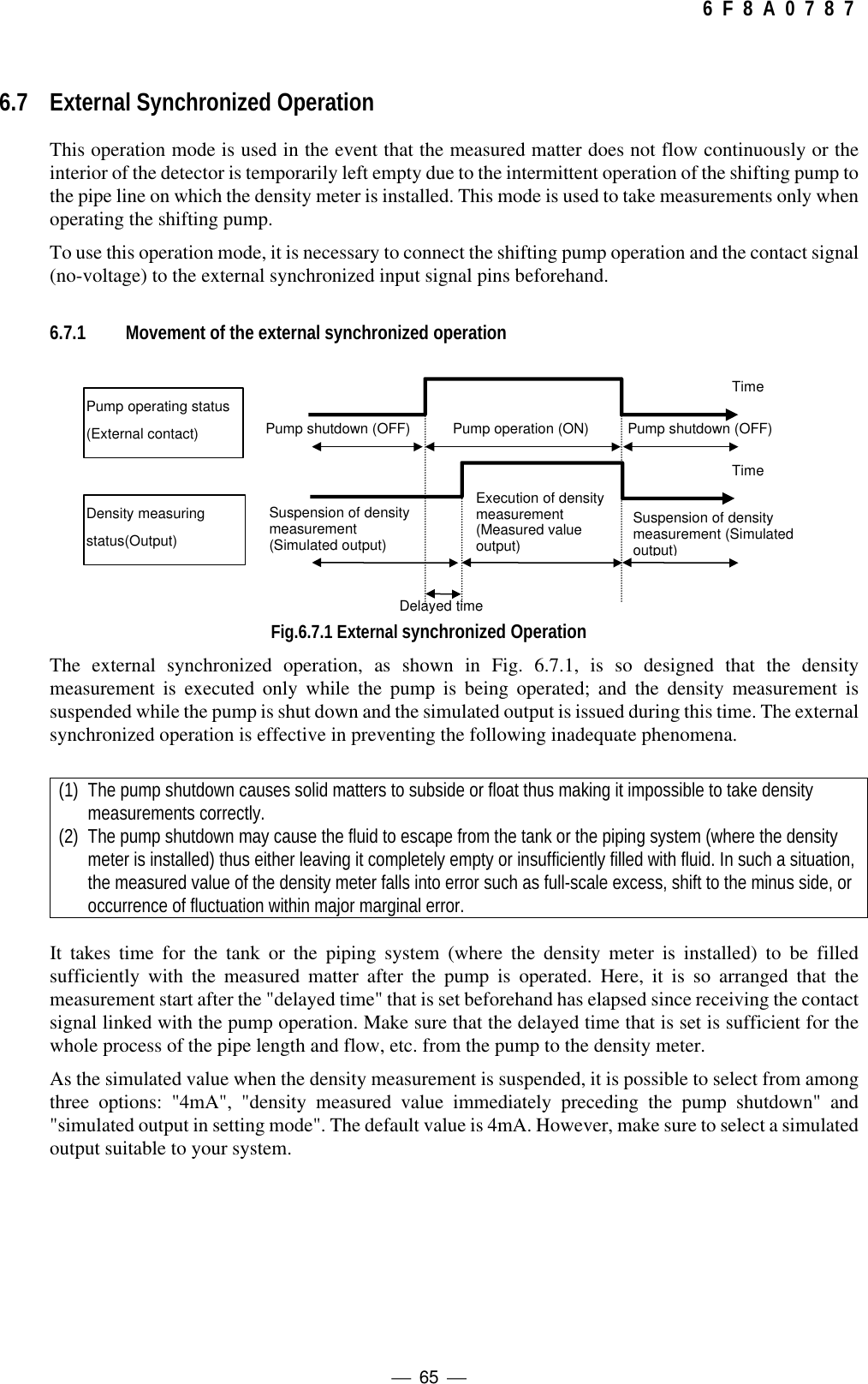
![ 66 6 F 8 A 0 7 8 76.7.2 Setting the external synchronized operation(1) Setting the delayed time (see Subsection 5.2.10)(1-1) Switching to the setting mode (see Subsection 5.2.5)First of all, press the [ESC] key of the converter several times (normally once although thisvaries with the operation status) to return to the initial menu display. Next, use the [→] keyto move the LCD indicator cursor to the menu number "2" of "2 SETTING MENU" andthen press the [SET] key to display the warning message saying "Test output will be valid."Make sure that there is no problem and then press [→] to get into the setting mode. To getinto [2: SETTING MENU], it is necessary to further enter the password "8000". Then, theoutput will be switched to the simulated output that is set beforehand.(1-2) Selecting the parameter setting menu (see Subsection 5.25)The menu list of menu numbers 5 to 8 is displayed. Use the [→] key to move the LCDindicator cursor to the menu number "5" of "5: SET PARAMETERS" and then press the[SET] key to select the menu of "5: SET PARAMETERS."(1-3) Setting the delayed time at the time of external synchronized(see Subsection 5.2.10)Press the [UP] key five times to select the setting menu of the delayed time at the time ofexternal synchronized(dt: DELAYED SYNC. TIME). Press the [SET] key to get into theset value input screen and then enter an appropriate value (the time sufficient for themeasured matter to flow up to the density meter and fill up the pipe after the shifting pumpoperation is started). Use the [→] key to move from one digit to another. Use the [UP] and[DN] keys to switch around the number of the relevant digit. When the input is completed,press the [SET] key to confirm it. Then, the display will be returned to the immediatelypreceding menu screen. Verify that the resetting has been done correctly.(2) Setting the simulated output at measurement suspension (at external contact OFF)(see Subsection 5.2.16)As the simulated output when the measurement is suspended (at external contact OFF), it ispossible to select from among three options as shown in Table 6.7.1. Make sure to select asimulated output suitable to your system.Table 6.7.1 Density Display and Output at Measurement Suspension in External SynchronizedOperationMode Density Indicator Display Output (4 - 20mA)"LAST" Holds the density measured valueimmediately before OFFHolds the density measured valuecorrespondence output immediatelybefore OFF"4mA" (Standard) Held in 0%TS Output held in 4mA"TEST" same as the simulated output valuein setting modeSame as the simulated output valuecorrespondence output in settingmode"LAST" Holds the density measured valueimmediately before OFFHolds the density measured valuecorrespondence output immediatelybefore OFF](https://usermanual.wiki/Toshiba/62372311/User-Guide-231580-Page-68.png)
![ 67 6 F 8 A 0 7 8 7(2-1) Selecting the "OTHERS" setting menu (see Subsection 5.2.5)Continuing on from (1), press the [ESC] key to return to the display of menus 5 to 8 insetting mode. Press the [UP] key to switch to the display of the next menus 9 to 11. Use the[→] key to move the cursor of the LCD indicator to the menu number "11" of "11:OTHERS" and press the [SET] key to select the "11: OTHERS" menu.(2-2) Setting the output mode at contact OFF in external synchronized operation (see 5.2.16)The current output mode at contact OFF in external synchronized operation is displayed inthe initial menu "ho: 4-20mA IN [EXT]" of "11: OTHERS". To make changes, it isnecessary to press the [SET] key and place the software in the setup state. Each time the[UP] or [DN] key is pressed, the mode display is switched around from "LAST"(immediately preceding value), through "4mA" to "TEST" (the simulated output value insetting mode). Press the [SET] key on the display in the selected mode to confirm. Thescreen is returned to that of the immediately preceding menu screen. Make sure that theresetting is done correctly.(2-3) Returning to the measuring modePress the [ESC] key twice to return to the initial menu and return from the setting mode tothe measuring mode to resume the normal measurement.(3) Setting the operation mode(3-1) Selecting the operation mode change menu (see Subsection 5.2.6)In the initial menu, use the [→] key to move the cursor of the LCD indicator to the menunumber "3" of "3: MEASURING MODE" and then press the [SET] key to get into theoperation mode menu.(3-2) Verifying and setting the operation modeThe current operation mode is displayed at "DATA" of the LCD indicator . "CONT" refersto the mode of taking measures continuously without relying on the status of the externalcontact signal, whereas "EXT" refers to the external synchronized operation mode. If thecurrent setting is "CONT," press the [SET] key to get into the setup screen of operationmode; press the [UP] or [DN] key to switch the set value of the operation mode to "EXT";and press the [SET] key to confirm. The screen is returned to the immediately precedingmenu screen. Make sure that the resetting has been done correctly.(4) Starting the external synchronized operationWith the settings above, measurement ON/OFF are proceeded with as shown in Fig.6.7.1 inaccordance with external synchronized contact signal ON/OFF.6.8 Functions Related to OperationTo enable you to use the Insertion Type Density Meter LQ300A00****** more appropriately invarious processes and situations, the device is equipped with various functions including the movingaverage, the change-rate limit, the electric conductivity correction, the additive correction, the linearizerand the density multiplier switching by external signals. Make settings necessary for using thesefunctions appropriately where necessary. For details, please refer to Chapter 10.](https://usermanual.wiki/Toshiba/62372311/User-Guide-231580-Page-69.png)
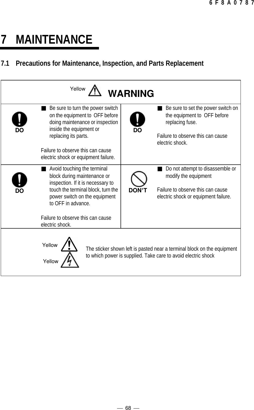
![ 69 6 F 8 A 0 7 8 77.2 Maintenance and Inspection ItemsPeriodic maintenance and inspection is necessary for reliable measurement over a long period of time.Since the density meter has no mechanically moving parts, however, it does not require replacement ofmechanism elements in a normal operating environment.Compare the density measured value and the manually analyzed value in the cycle shown in Table 7.1.If necessary, implement the span calibration after implementing the zero calibration. The spare partsthat must be kept on hand are the fuses in Table 7.2.Table 7.1 Maintenance and Inspection ItemsItem Cycle RemarksComparison of density meter measured valuewith manually analyzed value When necessary At least three samples aredesirable.Materials accumulated or entangled, orphysical damage When necessary◆If the density meter measured value deviates from the manually analyzed value to the extent of causingobstacles, implement the span calibration (changing the density multiplier C) while referring to Section6.5.◆If the density meter measured value greatly deviates from the manually analyzed value by less thanhalf or more than twice, implement the span calibration after implementing the zero calibration whilereferring to Section 6.4 and 6.5.◆When the density meter is used in an application where the process fluid contains plenty of fur or fiber,these substances may accumulate or entangle in the insertion probe area and thus perform themaintenance and inspection operation, and cleaning periodically.◆Take extra care not let the applicators (antenna) hit the hard object.Table 7.2 Spare PartsName Specifications QtyFuse 1A(M),250V cartridge, glass tubular fuse,5.2mm outer dia. x 20mm long 2◆Fuses are parts with expected life span. Therefore, replace them periodically. (Recommendedreplacement cycle: about 3 years)◆In general, the service life of an electronic part becomes shorter at higher ambient temperature.Electrolytic capacitors are used in the converter and their service life is about 10 years at the ambienttemperature of 20°C or about 3 years at 50°C. For stable use of the meter for many years, it is desirableto replace these parts in time. When replacing the capacitors, please contact Toshiba's Service Dept.◆In the event that the characters on the LCD display becomes weak in contrast or edge, it is consideredthat the LCD display unit has reached the end of its life. Although such unsatisfactory visibility may notaffect the performance of the density measurement, the display unit should be replaced if it interfereswith the operation. When replacing the display unit, contact Toshiba's Service Dept.[NOTE][NOTE]](https://usermanual.wiki/Toshiba/62372311/User-Guide-231580-Page-71.png)
![ 70 6 F 8 A 0 7 8 78TROUBLESHOOTING8.1 TroubleshootingIf any trouble has developed, make a careful check and take appropriate steps. Table 8.1 shows possibletroubles, their causes, and remedies. If anything wrong occurs, refer to the table below and take thenecessary steps. If that does not remedy the trouble, send information on the trouble, in as much detail aspossible, and self-diagnosis data to our Service Department.Table 8.1 Troubleshooting (1)No. Trouble Cause RemedyAC power is not supplied.Check terminals [L1] and [L2] onterminal block with voltage tester. IfAC voltage is not supplied, supplyAC power in accordance withspecifications.1Converter power cannot beswitched on.Fuse (1A) is blown. Replace fuse.2ALARM indicator lights;density meter error contactoutput.. Fault in the density meterIn accordance with Section 8.2,perform self-diagnosis data checkand restoration operations. IfALARM indicator lights again, sendself-diagnosis data to our ServiceDepartment.3While the flow is stagnant,the indicator is in error.The fluid drained out in the pipingsystem where the density meter isinstalled.4While the flow is stagnant,the measured density valueslowly increases ordecreases.Density becomes uneven because themeasurement object fluid in the fluid inthe pipe starts to sinks or floats, thuscausing the density in the centerportion of measured fluid to increaseor decrease.Use the externally synchronizedoperation.See Section 6.7.(Density meter is not faulty.)](https://usermanual.wiki/Toshiba/62372311/User-Guide-231580-Page-72.png)
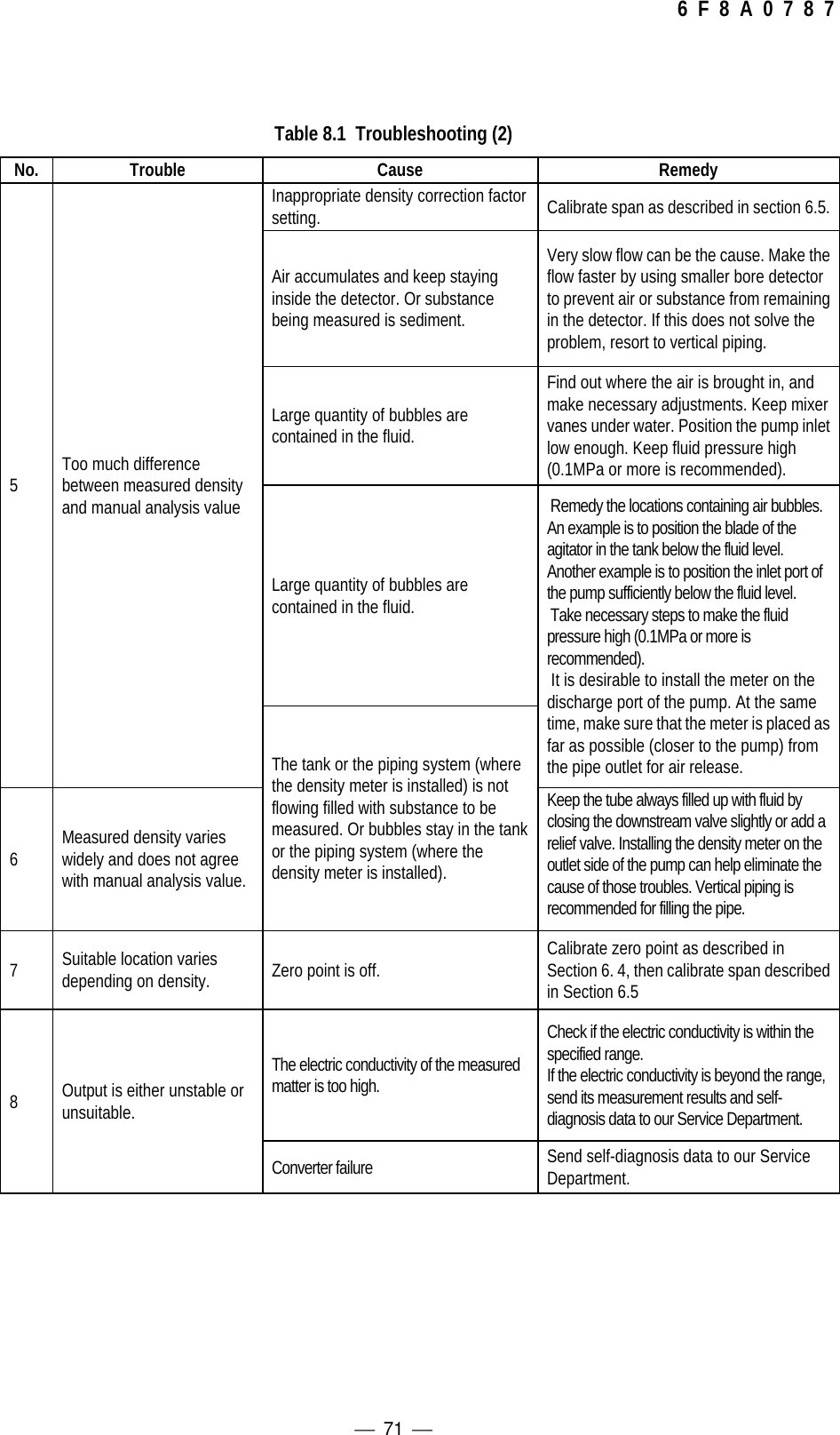
![ 72 6 F 8 A 0 7 8 78.2 Error Indications and Recovery OperationsIf an error occurs to the density meter, the error indicator [ALARM] will light up and a contact signal(OFF) will be output.Check the self-diagnosis data for any faulty values in accordance with the following steps.(1) Monitor menu display (see Subsection 5.2.4)First of all, press the [ESC] key of the converter several times (normally once although this varieswith the operation status) to return to the initial menu display. Next, use the [→] key to move theLCD indicator cursor to the menu number "1" of "1: MONITORING MENU" and then press the[SET] key. (The cursor of the initial state is located on "1".)(2) Switching to the self-diagnosis menu (see Subsection 5.2.7)In the monitoring menu, use the [→] key to move the cursor of the LCD indicator to the menunumber "3" of "3: SELF-DIAGNOSIS" and then press the [SET] key.(3) Checking the self-diagnosis data (see Subsection 5.2.9)Press the [UP] key to move from one self-diagnosis data to another to check for any error.◆To detect which numerical range is an error value, please refer to Table 8.2.(4) Terminating the self-diagnosisAfter checking, press the [ESC] key twice to return to the initial menu display. If an error value is found, turn off all the power switches of the converter and then turn them back on.The self-diagnosis is executed all over again by the powering-ON. If an error is displayed again as aresult of the self-diagnosis, send the relevant item to our Service Department.](https://usermanual.wiki/Toshiba/62372311/User-Guide-231580-Page-74.png)
![ 73 6 F 8 A 0 7 8 7Table 8.2 Self-diagnosis dataData ItemSymbol Item name Data Status Data(Numeric value range; normal data range,status)ST Status[STATUS]Normal [GOOD]Warning [WARNING.]Whether the phasemeasurement operation isnormally functioning or notcan be verified.SL Microwave received signallevel[MICROWAVE SIG. LVL]Without error judgmentbased on data numeric Usual range: -90 to -40 (dBm)FMicrowave coef.[MICROWAVE COEF.]Without error judgmentbased on data numeric • Normal range: 1825 to 1975GData concerningmicrowave phasemeasurement [RF DATA]Without error judgmentbased on data numeric • Normal range + 10.0 to + 80.0J+5 V voltage[+5V POWER SUPPLY] Without error judgmentbased on data numeric • Normal range 4.5 to 5.5 (V)pd Reference phase error[REF PHASE]Without error judgmentbased on data numeric • Normal range - 9.9 to + 9.9 (degrees)PMemory check[MEMORY CHECK]• Norma1 [GOOD]• Abnormal [N.G.] EPROM, RAM, EEPROM are checked](https://usermanual.wiki/Toshiba/62372311/User-Guide-231580-Page-75.png)
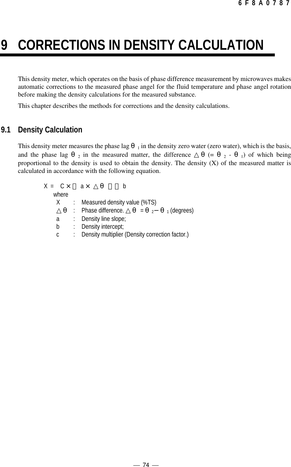
![ 75 6 F 8 A 0 7 8 79.2 Various Kinds of Corrections9.2.1 Phase angle rotation correctionThe phase is available only from 0 degree to 360 degrees. If the phase incrementally reaches 360degrees, it returns to 0 degree, from which it keeps incrementing again. If the phase decreasinglyreaches 0 degrees, it returns to 360 degrees, from which it keeps decreasing again. Accordingly, theconcept of phase angle rotation is incorporated into this density meter and some corrections have beenmade so to allow the phase to change to an unlimited extent. In such a manner, this density meter hasovercome the limit that the phase is available only from 0 to 360 degrees, thus realizing high densitymeasurement.Phase angle rotation correction refers to obtaining the real phase angle θ2 by judging the number ofrotations the dummy angle θ2' belongs to based on the measured values coming before and after.θ2 = θ2' + N x 360 (degrees)N: Number of rotationsSet N=0 at the time of zero calibration, making the number of rotations to zero for the phase angleθ1 at zero point.If the θ2' exceeds 360 degrees to enter into the next rotation, set N=1. If it again exceeds 360degrees to enter into the rotation after the next rotation, set N=2.(N will move up to 2 only if the meter is of large diameter and the density is high.)On the other hand, if θ2' goes below zero (0) degree to enter into the previous rotation, decreaseN by one (1). In other words, when it goes into the -1st rotation from the 0th one, set N=−1; andwhen into the 0th rotation from the 1st one, set N=0.Note: The description above is the basics regarding the phase angle rotation correction. Normally, it isall right to use the density meter without being aware of this correction. However, in the event ofmeasuring high density, etc., special setups and actions may be needed. For details, refer toSection 9.3.9.2.2 Liquid temperature correctionThe phase tends to change in a straight line with regard to the liquid temperature. In this connection,liquid temperature correction is performed on θ2 as follows to obtain the phase difference △θ△θ={θ2−α(Τ−Τ0)}− θ1△θ :Phase difference [degrees]θ2 :Actual phase angle of measurement object liquid [degrees]θ1:Phase during zero water measurement (degrees)(Measured during zero calibration, and set in advance as a constant)α:Liquid temperature correction factor (degrees/°C)T :Temperature of measurement object liquid (°C)T 0 :Liquid temperature during zero calibration (°C)(Measured during zero calibration, and set in advance as a constant)](https://usermanual.wiki/Toshiba/62372311/User-Guide-231580-Page-77.png)
![ 76 6 F 8 A 0 7 8 79.2.3 RF correctionIn addition to the liquid temperature correction, the density meter is equipped with the RF correctionfunction in accordance with the features of the converter. The correction is performed on θ2 as followsto obtain the phase difference △θ.△θ={θ2−α(Τ−Τ0)−δ(G−G0)}−θ1△θ :Phase difference [degrees]θ2:Actual phase angle of measurement object liquid [degrees]θ1:Phase during zero water measurement (degrees)(Measured during zero point calibration, and set in advance as a constant)α:Liquid temperature correction factor (degrees/°C)T :Temperature of measurement object liquid (°C)T 0 :Liquid temperature during zero calibration (°C)(Measured during zero calibration, and set in advance as a constant)δ:RF correction factorG:RF data during measurementG0:Zero point RF data(Measured during zero point calibration, and set in advance as a constant)9.2.4Atmospheric temperature correctionIn addition to the liquid temperature correction and the RF correction, the density meter is equippedwith the atmospheric temperature correction function in accordance with the features of the converter.The correction is performed on θ2 as follows to obtain the phase difference △θ.<IMPORTANT> Atmospheric temperature correction function is an option item, therefore, make sureto set the atmospheric temperature correction factor β to “0.00”.△θ={θ2−α(Τ−Τ0)−δ(G−G0)−β(A−A0)}−θ1△θ :Phase difference [degrees]θ2:Actual phase angle of measurement object liquid [degrees]θ1:Phase during zero water measurement (degrees)(Measured during zero point calibration, and set in advance as a constant)α:Liquid correction factor (degrees/°C)Τ:Temperature of measurement object liquid (°C)Τ0:Liquid temperature during zero adjustment (°C)(Measured during zero point calibration, and set in advance as a constant)δ:RF correction factorG:RF data during measurementG0:Zero point RF data(Measured during zero point calibration, and set in advance as a constant)β:Atmospheric temperature correction factor (degrees/°C)A:Atmospheric temperature of measurement object liquid (°C)A0:Atmospheric temperature during zero adjustment (°C)(Measured during zero point calibration, and set in advance as a constant)](https://usermanual.wiki/Toshiba/62372311/User-Guide-231580-Page-78.png)
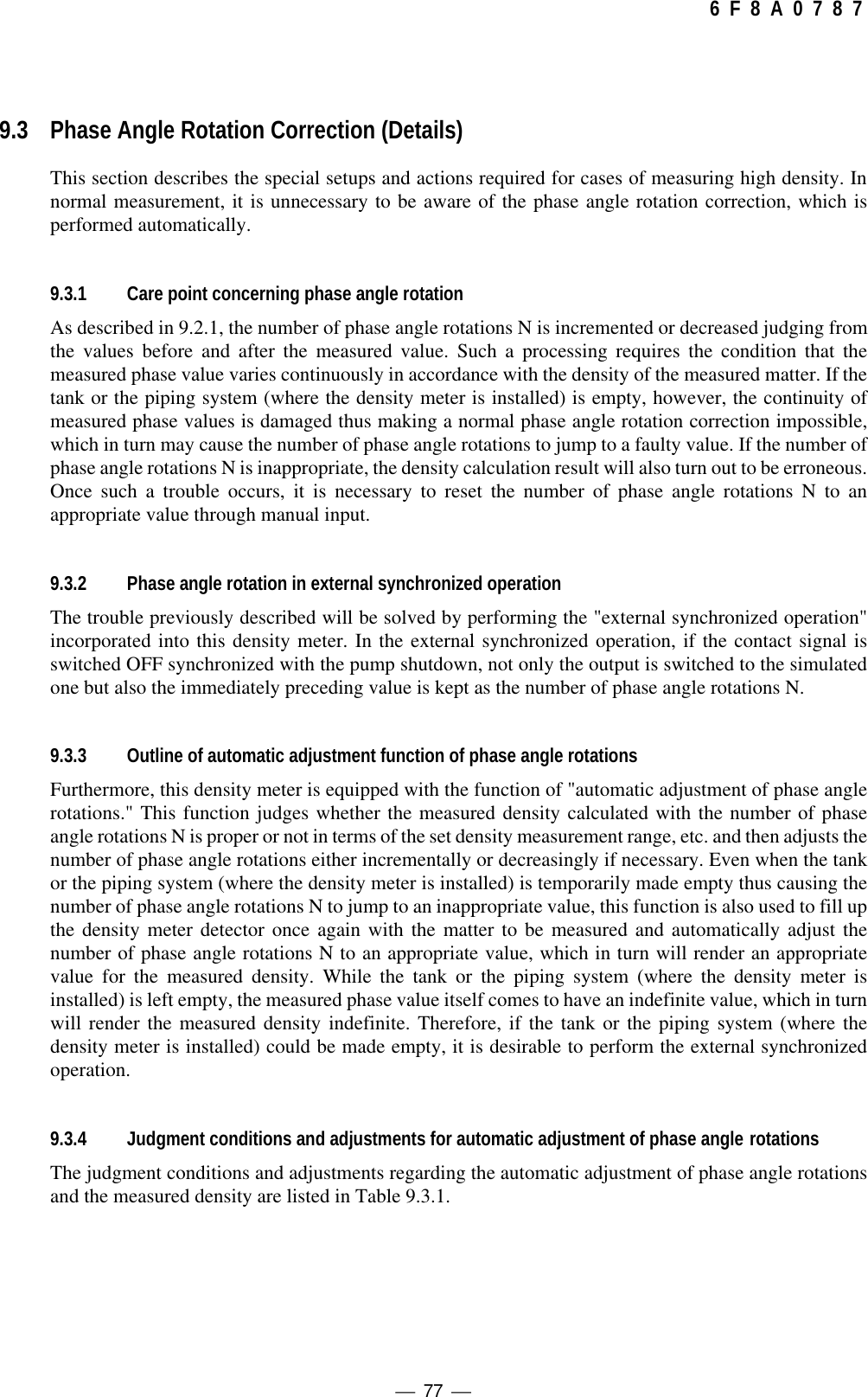
![ 78 6 F 8 A 0 7 8 7Table 9.3.1 Judgement Conditions and Adjustments for Automatic Adjustment of Phase AngleRotationsMeasured Density Automatic Adjustment of Phase Angle Rotations NXmin = Less than - 4(%TS) Incremented (N = N+1)- 4∼C×a×360(%TS) UnadjustedXmax = More than C x a x 360 (%TS) Decreased (N = N-1)In Table 9.3.1 above,C: Density multiplier (Varies with the character of the measured matter.)a: Density slope (A constant determined by the meter size)Table 9.3.2 is shown when C = 1, 0.7 and 1.8 as examples of the value Xmax in which N is judged to betoo large. To obtain the value, multiplied the value when C = 1 in Table 9.3.2 by C.Table 9.3.2 Xmax Value (%TS)CXMAX0.7 21.171.0 30.241.8 54.439.3.5 Restrictions and invalidation in applying the automatic adjustment of phase angle rotationsThis function of automatic adjustment of phase angle rotations involves some application restrictions.For example, it cannot be applied to the case of measuring high density as follows.<Example> Upper density measurement range: 20%TS; and density multiplier: 0.7As shown in Table 9.3.2, Xmax=21.17(%TS). Therefore, when the measured densityexceeds 21.17(%TS), the adjustment of decreasing the number of phase angle rotationsapplies as shown in Table 9.3.1, thus making it impossible to measure the density inexcess of 21.17(%TS).To solve the problems as shown in the example above, measurement is taken so that the function ofautomatic adjustment of phase angle rotations is automatically invalidated if the upper measureddensity range exceeds Xmax.Check the operating conditions to see if the function of automatic adjustment of phase angle rotations isapplicable or not.In the cases where the automatic adjustment of phase angle rotations is not applicable, after the tank or the pipingsystem (where the density meter is installed) is temporarily made empty, it is necessary to reset the phase anglerotation to an appropriate value through manual input. In the cases, it is more desirable to perform the externalsynchronized operation.9.3.6 Invalidation by setting the automatic adjustment of phase angle rotationsAs mentioned in the previous subsection, the density meter is equipped with the function ofautomatically invalidating the function of automatic adjustment of phase angle rotations, based on theconditions for setting the upper density measurement range and the density multiplier. However, in thestate of starting the operation, the upper density measurement range is determined but the densitymultiplier is not determined yet (determined in the span calibration described in Section 6.5), thus theoperation is started with a provisional value (initial value: 1). Therefore, the function of automatic[NOTE]](https://usermanual.wiki/Toshiba/62372311/User-Guide-231580-Page-80.png)
![ 79 6 F 8 A 0 7 8 7adjustment of phase angle rotations, which is supposed to be invalidated, may not be invalidated,making it impossible to take an appropriate measurement (including the span calibration). This appliesto the case in which the original density multiplier is smaller than the current set value (the initial value1 in the initial operation).There are two ways of dealing with such a case.One is to automatically invalidate the function of automatic adjustment of phase angle rotations byprovisionally setting a sufficiently small value such as about 0.5 for the density multiplier C so thatXmax is smaller than the upper density measurement range.Another is to forcibly invalidate the function of automatic adjustment of phase angle rotations. Thelatter's setting method is described below.(1) Switching to the setting mode (see Subsection 5.2.5)First of all, press the [ESC] key of the converter several times (normally once although this varieswith the operation status) to return to the initial menu display. Next, use the [→] key to move theLCD indicator cursor to the menu number "2" of "2 SETTING MENU" and then press the [SET]key to display the warning message saying "Test output will be valid." Make sure that there is noproblem and then press [→] to get into the setting mode. To get into [2: SETTING MENU], it isnecessary to further enter the password "8000". Then, the output will be switched to thesimulated output that is set beforehand.(2) Selecting the "OTHERS" setting menu (see Subsection 5.2.5)Initially, the menu list of menu numbers 5 to 8 is displayed. However, by pressing the [UP] keyonce, this display can be switched to the menu list of the next menu numbers 9 to 11. Use the [→]key to move the LCD indicator cursor to the menu number "11" of "11: OTHERS" and then pressthe [SET] key to select the menu of "11: OTHERS."(3) Verifying or changing ON/OFF of automatic adjustment of phase angle rotations(See Subsection 5.2.16)Press the [DN] key once (or the [UP] key five times) to display "NA: N AUTO ADJUSTMENT".On this screen, it is possible to verify whether the automatic adjustment of phase angle rotationsis valid (ON) or invalid (OFF). Here, if it is necessary to alter the setting, press the [SET] key toswitch to the setup display of the automatic adjustment of phase angle rotations. Each time the[UP] or [DN] key is pressed, the set value is alternated between ON and OFF. Set the value toOFF and then press the [SET] key to confirm it. The screen will be returned to the immediatelypreceding one; make sure that the value is correctly reset.(4) Returning to the measuring mode Press the [ESC] key twice to return to the initial menu screen and return to the measuring modefrom the setting mode to resume the normal measurement.9.3.7 Actions after invalidating the automatic adjustment of phase angle rotationsAfter invalidating the automatic adjustment of phase angle rotations to make it possible to takemeasurements appropriately even at high density in excess of Xmax, implement the span calibration inaccordance with Section 6.5 and set the density multiplier to an appropriate value. While referring toTable 9.3.2, use this reset density multiplier to calculate the maximum density Xmax, which can beapplied to the function of automatic adjustment of phase angle rotations and judge whether this Xmax isgreater than the value of the upper density measurement range that is set.](https://usermanual.wiki/Toshiba/62372311/User-Guide-231580-Page-81.png)
![ 80 6 F 8 A 0 7 8 7If Xmax is greater than the upper density measurement range, the function of automatic adjustment ofphase angle rotations is applicable. Therefore, return the function of automatic adjustment of phaseangle rotations which is set to "OFF" in Subsection 9.3.6 to“ON”.If Xmax is smaller than the upper density measurement range, the function of automatic adjustment ofphase angle rotations is invalid. Therefore, it is unnecessary to return the function of automaticadjustment of phase angle rotations which is set to "OFF" in Subsection 9.3.6 to “ON”.9.3.8 Return to the normal through manual input of the phase angle rotationsIf the function of automatic adjustment of phase angle rotations is not applicable whereas the pipingsystem (where the density meter is installed) is temporarily made empty thus causing the number ofphase angle rotations to jump to a faulty number, the number of phase angle rotations fails to return toan appropriate value even when the piping system (where the density meter is installed) is refilled withthe matter to be measured, thus allowing the measured density to remain in error. In this connection, it isnecessary to reset the phase angle rotation to an appropriate value through manual input. The settingmethod is described below.(1) Switching to the setting mode (see Subsection 5.2.5)First of all, press the [ESC] key of the converter several times (normally once although this varieswith the operation status) to return to the initial menu display. Next, use the [→] key to move theLCD indicator cursor to the menu number "2" of "2 SETTING MENU" and then press the [SET]key to display the warning message saying "Test output will be valid." Make sure that there is noproblem and then press [→] to get into the setting mode. To get into [2: SETTING MENU], it isnecessary to further enter the password "8000". Then, the output will be switched to thesimulated output that is set beforehand.(2) Selecting the "ANGLE ROTATION" setting menu (see Subsection 5.2.5)In the state that the menu list of menu numbers 5 to 8 is displayed, use the [→] key to move theLCD indicator cursor to the menu number "8" of "8: ANGLE ROTATION" and then press the[SET] key to select the menu of "8: ANGLE ROTATION".(3) Verifying or changing the number of phase angle rotations (see Subsection 5.2.13)Press the [DN] key once (or the [UP] key twice) to display "N: ROTATION". On this screen, it ispossible to verify the number of phase angle rotations. Here, press the [SET] key to switch to thesetup display of the number of phase angle rotations and enter an appropriate value (note). At theinitial digit, use the [UP] or [DN] key to select whether to attach the "-" symbol or not. Use the[→] key to move to the digit, and use the [UP] or [DN] key to alter the numeric value of therelevant digit. When entering input is completed, press the [SET] key to confirm it. The screenwill be returned to the immediately preceding one; make sure that the value is correctly reset.Note: In many cases, an appropriate value for the number of phase angle rotations N is 0. In theevent that the density or the fluid temperature is high, this value may be 1. In the event thatthe density or the fluid temperature is low, it may be -1. Set either of 0, 1 and -1 and thenverify that the measured density at this time has returned to an appropriate value.(4) Returning to the measuring modePress the [ESC] key twice to return to the initial menu screen and return to the measuring modefrom the setting mode to resume the normal measurement.](https://usermanual.wiki/Toshiba/62372311/User-Guide-231580-Page-82.png)
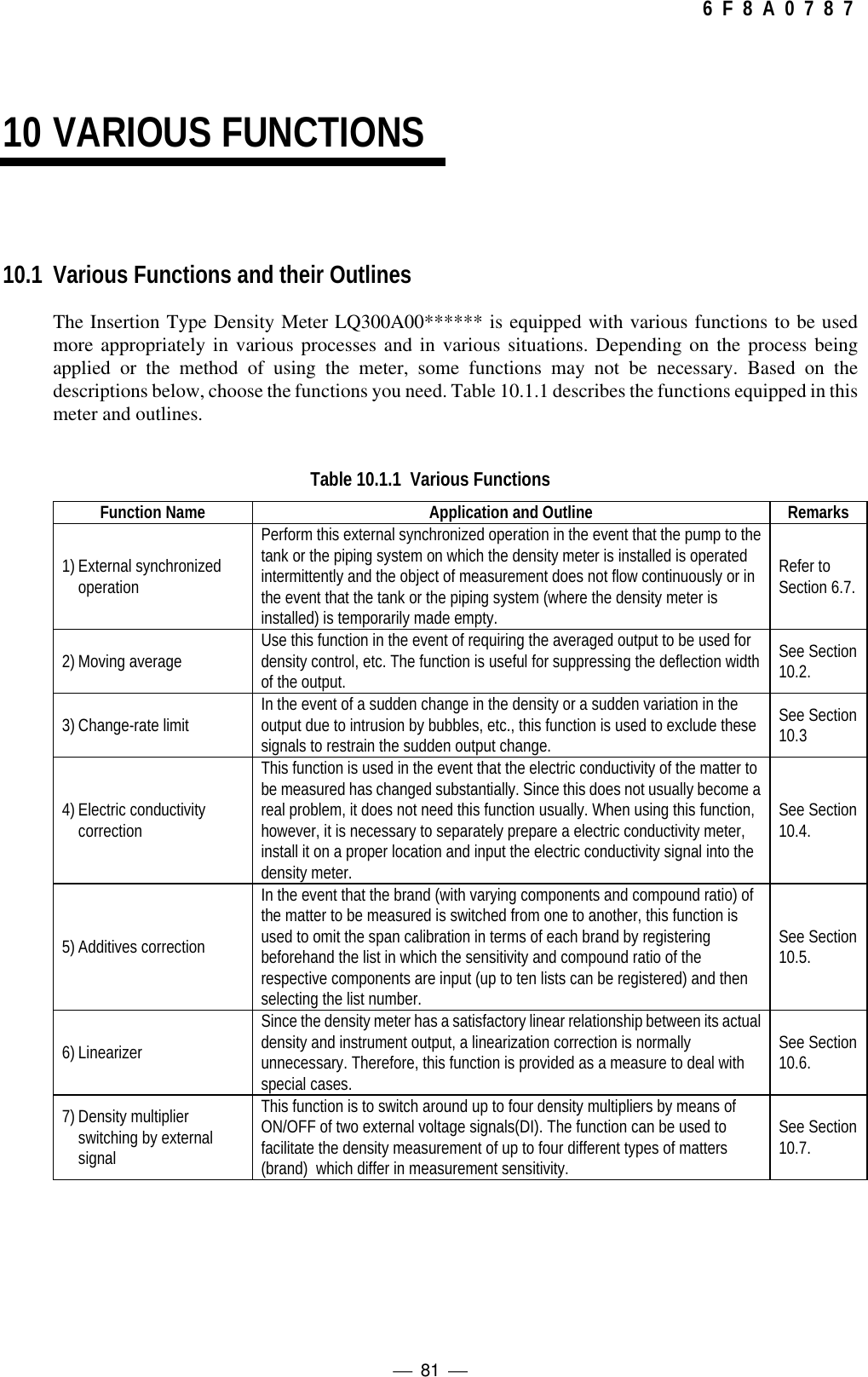
![ 82 6 F 8 A 0 7 8 710.2 Moving Average10.2.1 Function of moving averageAssuming that the moving average times is "n", this function is to calculate and output the mean value ofn preceding measured values each time. The function is used when an averaged output is required suchas for density control. This function is also useful for suppressing the deflection width of output.The value that can be set as the moving average times "n" is 1 to 99. Setting 1 for "n" means that nomoving average takes place.10.2.2 Setting of the moving average times(1) Switching to the setting mode (see Subsection 5.2.5)First of all, press the [ESC] key of the converter several times (normally once although this varieswith the operation status) to return to the initial menu display. Next, use the [→] key to move theLCD indicator cursor to the menu number "2" of "2 SETTING MENU" and then press the [SET]key to display the warning message saying "Test output will be valid." Make sure that there is noproblem and then press [→] to get into the setting mode. To get into [2: SETTING MENU], it isnecessary to further enter the password "8000". Then, the output will be switched to thesimulated output that is set beforehand.(2) Selecting the parameter setting menu (see Subsection 5.2.10)In the state that the menu list of menu numbers 5 to 8 is displayed, use the [→] key to move theLCD indicator cursor to the menu number "5" of "5: SET PARAMETERS" and then press the[SET] key to select the menu of "5: SET PARAMETERS."(3) Verifying or setting the moving average times (see Subsection 5.2.10)Press the [DN] key three times (or the [UP] key eleven times) to display "ma: AVERAGINGTIMES". On this screen, it is possible to verify the set value of the moving average times. If it isnecessary to change the setting, press the [SET] key here to switch to the setup display of themoving average times and enter an appropriate value. Use the [→] key to move to the digit, anduse the [UP] or [DN] key to alter the numeric value of the relevant digit. When entering input iscompleted, press the [SET] key to confirm it. The screen will be returned to the immediatelypreceding one; make sure that the value is correctly reset.(4) Returning to the measuring modePress the [ESC] key twice to return to the initial menu screen and return to the measuring modefrom the setting mode to resume the normal measurement.10.2.3 Cautions in using the moving average functionSetting an excessively large value for the moving average times will result in deterioratedresponsiveness. Therefore, make sure to set a value appropriate to the process situation and the requiredresponsiveness.](https://usermanual.wiki/Toshiba/62372311/User-Guide-231580-Page-84.png)
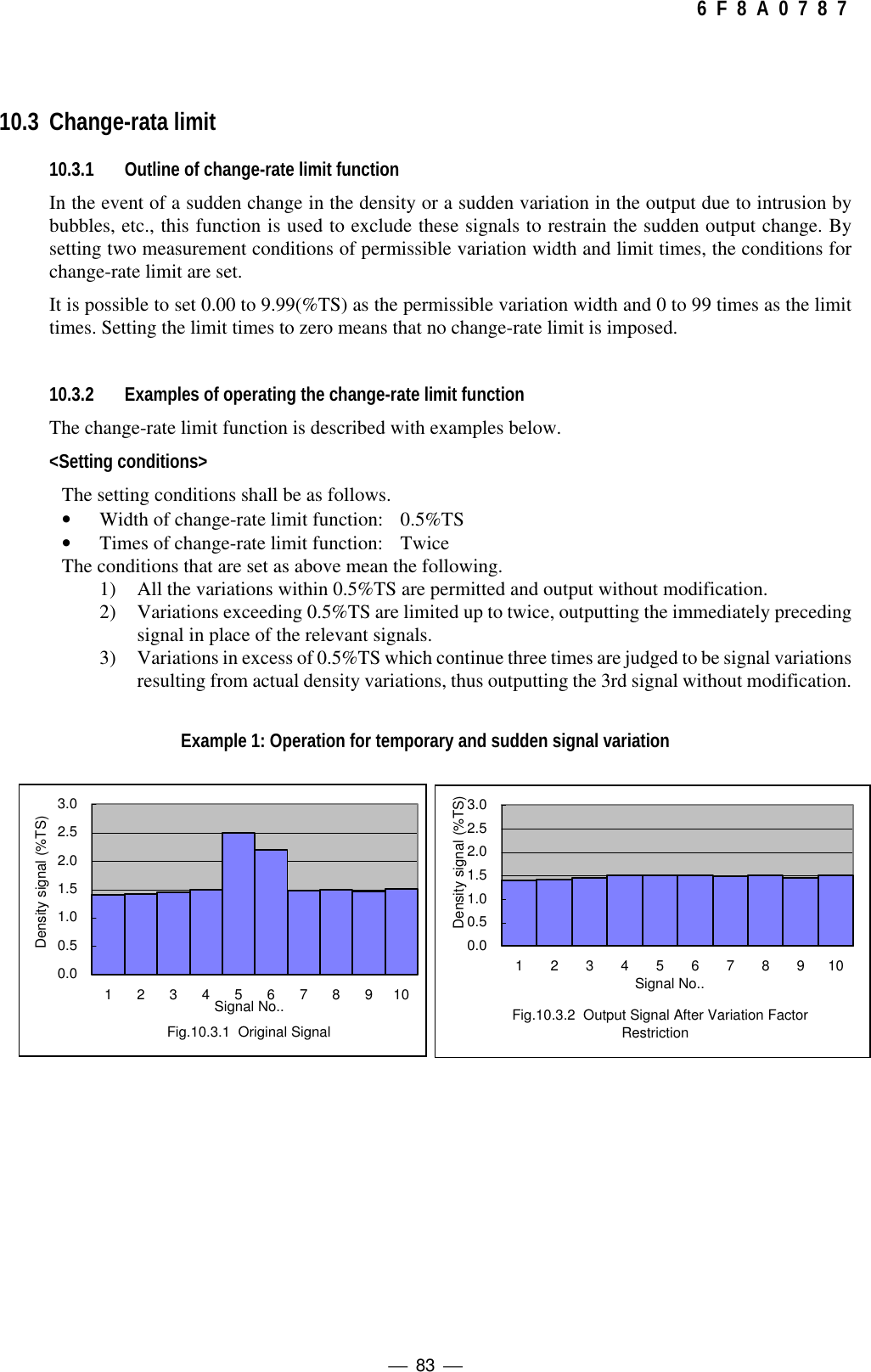
![ 85 6 F 8 A 0 7 8 7steps as shown in Example 2, a delay increases in accordance with the set times. Set anappropriate value for the times in accordance with the responsiveness required of the plant.10.3.4 Setting the change-rate limit(1) Switching to the setting mode (see Subsection 5.2.5)First of all, press the [ESC] key of the converter several times (normally once although this varieswith the operation status) to return to the initial menu display. Next, use the [→] key to move theLCD indicator cursor to the menu number "2" of "2 SETTING MENU" and then press the [SET]key to display the warning message saying "Test output will be valid". Make sure that there is noproblem and then press [→] to get into the setting mode. To get into [2: SETTING MENU], it isnecessary to further enter the password "8000". Then, the output will be switched to thesimulated output that is set beforehand.(2) Selecting the parameter setting menu (see Subsection 5.2.5)In the state that the menu list of menu numbers 5 to 8 is displayed, use the [→] key to move theLCD indicator cursor to the menu number "5" of "5: SET PARAMETERS" and then press the[SET] key to select the menu of "5: SET PARAMETERS".(3) Verifying or changing the change-rate limit width (see Subsection 5.2.10)Press the [DN] key two times (or the [UP] key twelve times) to display "dx: CHANGE RATELIMIT". On this screen, it is possible to verify the set value of the change-rate limit width. If it isnecessary to change the setting, press the [SET] key here to switch to the setup display of thechange-rate limit width and enter an appropriate value for the width. Use the [→] key to move tothe digit, and use the [UP] or [DN] key to alter the numeric value of the relevant digit. Whenentering input is completed, press the [SET] key to confirm it. The screen will be returned to theimmediately preceding one; make sure that the value is correctly reset.(4) Verifying or changing the times of change-rate limit (see Subsection 5.2.10)Continuing on from the operation in (3) above, press the [UP] key once to display "HL: LIMITTIMES". On this screen, it is possible to verify the set value of the change-rate limit times. If it isnecessary to change the setting, press the [SET] key here to switch to the setup display of thechange-rate limit times and enter an appropriate value for the times. Use the [→] key to move tothe digit, and use the [UP] or [DN] key to alter the numeric value of the relevant digit. Whenentering input is completed, press the [SET] key to confirm it. The screen will be returned to theimmediately preceding one; make sure that the value is correctly reset.Note: If the times of change-rate limit is set to zero, the change-rate limit function is madeinactive.(5) Returning to the measuring modePress the [ESC] key twice to return to the initial menu screen and return to the measuring modefrom the setting mode to resume the normal measurement.](https://usermanual.wiki/Toshiba/62372311/User-Guide-231580-Page-87.png)
![ 86 6 F 8 A 0 7 8 710.4 Electric Conductivity Correction10.4.1 Standard conductivity correction factorThe indication of the density meter varies with the conductivity of the measured object fluid; however,the variance is as small as approx. 0.15%TS to 1mS/cm change in conductivity and usually practicallynegligible, thus making it unnecessary to input the conductivity meter signal to perform electricconductivity correction. In the event that the conductivity change is large and thus its impact is notignoble, make sure to use the electric conductivity correction function. The formula for this correctionincluding the other corrections described in Chapter 9 is as follows.△θ={θ2 -α(Τ-Τ0)-δ(G-G0)-γ(E-E0) - β(A - A0)} -θ1△θ :Phase difference (degrees)θ2:Actual phase angle of measured object liquid (degrees)θ1:Phase during zero water measurement (degrees)(Measured during zero calibration, and set in advance as a constant)α:Liquid temperature correction factor (degrees/°C)Τ:Liquid temperature of measured object liquid (°C)Τ0:Liquid temperature during zero calibration(Measured during zero calibration, and set in advance as a constant)δ:RF correction factorG:RF data during measurementG0:Zero point RF data(Measured during zero calibration, and set in advance as a constant)γ:Electric conductivity correction factor (degrees/(mS/cm))E:Electric conductivity of measured object liquid (mS/cm)E0:Zero water conductivity (mS/cm)β:Atmospheric temperature correction factor (degrees/°C)A:Atmospheric temperature of measured object liquid (°C)A0:Atmospheric temperature during zero calibration(Measured during zero calibration, and set in advance as a constant)At the time of factory shipment, the [electric conductivity correction factor γ] is set to zero for all theproducts. If the conductivity change of the measured object fluid is large, input the electric conductivitysignal in accordance with "Fig.3.5 External Connection Diagram" and then reset the [electricconductivity correction factor γ].Table 10.4.1 shows the "standard values" of electric conductivity correction factors as well as the"density line slope (a)" required in the event of obtaining electric conductivity correction factorsthrough calculation from measured values. The "standard values" shall be applicable when the range ofthe electric conductivity meter used for conductivity correction is 0 to 10 mS/cm.](https://usermanual.wiki/Toshiba/62372311/User-Guide-231580-Page-88.png)
![ 87 6 F 8 A 0 7 8 7Table 10.4.1 Standard Values of Electric Conductivity Correction Factor (γ) (Based on ElectricConductivity Meter with a Range of 0 to 10 mS/cm) and Slope of the Line (a)Item (a)γ (Standard Value)Multiplier 0.084 1.8In the event of performing a electric conductivity correction on this density meter, it is a basic principleto externally connect and use a conductivity meter with a range of 0 to 10 mS/cm. In the event of usinga conductivity meter of another range (0 - R mS/cm), obtain the conductivity correction factor inaccordance with the following formula.γ=(R/10)×γ0γ0 : Standard value of electric conductivity correction factor (see Table 9.1)R: Upper range of conductivity meter usedFor example, if the insertion type density meter, the standard value of the electric conductivitycorrection factor of the density meter is 2.7 and a conductivity meter with a range of 0 to 5 mS/cm isconnected to this,γ=(R/10)×γ0 =(5×10)×1.8 =0.9is used as the correction factor.◆In the event of implementing a electric conductivity correction, separately prepare a electric conductivitymeter and install it on a location where the conductivity can be measured correctly (where the measurementobject process is appropriate).◆The "standard values" of electric conductivity correction factors shown in Table 10.4.1 are criteria. It isnecessary to use the linear relationship that exists between the conductivity and the output to survey anddetermine the electric conductivity correction factor in terms of each actual measured object fluid. SeeSubsection 10.4.2.◆In the event of not executing any electric conductivity correction, set the "electric conductivity correctionfactor (γ)" to zero.10.4.2 How to obtain and set a correction factorObtain and set a electric conductivity correction factor as appropriate to the applicable process inaccordance with the following procedure.(1) To set the density multiplier to 1.000(1-1) Switching to the setting mode (see Subsection 5.2.5)First of all, press the [ESC] key of the converter several times (normally once although thisvaries with the operation status) to return to the initial menu display. Next, use the [→] keyto move the LCD indicator cursor to the menu number "2" of "2: SETTING MENU" andthen press the [SET] key to display the warning message saying "Test output will be valid."Make sure that there is no problem and then press [→] to get into the setting mode. To getinto [2: SETTING MENU], it is necessary to further enter the password "8000". Then, theoutput will be switched to the simulated output that is set beforehand.[NOTE]](https://usermanual.wiki/Toshiba/62372311/User-Guide-231580-Page-89.png)
![ 88 6 F 8 A 0 7 8 7(1-2) Selecting the span calibration menu (see Subsection 5.2.5)The menu list of menu numbers 5 to 8 is displayed. Use the [→] key to move the LCDindicator cursor to the menu number "7" of "7: SPAN CALIBRATION" and then press the[SET] key to select the menu of "7: SPAN CALIBRATION."(1-3) Verifying or recording the density multiplier (see Subsection 5.2.12)For example, the set value of the current density multiplier C' is displayed as in "DATA:1.265". Record this value.(1-4) Setting the density multiplier to "1.000" (see Subsection 5.2.12)Press the [SET] key to switch to the setup display of the density multiplier and reset thedensity multiplier to 1.000. Use the [→] key to move to the digit, and use the [DN] key toalter the numeric value of the relevant digit. When entering input is completed, press the[SET] key to confirm it. The screen will be returned to the immediately preceding one;make sure that the value is correctly reset.(2) To suspend the electric conductivity correction function (with the conductivity correction factorset to 0.00)(2-1) Returning to the initial screen of the setting modeContinuing on from (1-4) above, press the [ESC] key once to return to the menu list displayof the menu numbers 5 to 8 of the setting mode.(2-2) Selecting the linearizer /conductivity menu (see Subsection 5.2.5)Press the [UP] key once to switch to the menu list display of the next menu numbers 9 to11. Use the [→] key to move the cursor of the LCD indicator to the menu number "9" of "9:LINEARIZ/CNDUCTVTY" and then press the [SET] key to select the menu of "9:LINEARIZ/CNDUCTVTY".(2-3) Setting the electric conductivity correction factor to 0.00 (see Subsection 5.2.14)Press the [UP] key five times (or the [DN] key three times) to display "r: CNDUCTVTYCOEF". Press the [SET] key here to switch to the setup display of the electric conductivitycorrection factor and then input 0.00 for the electric conductivity correction factor. Use the[→] key to move to the digit, and use the [DN] key to alter the numeric value of therelevant digit. When entering input is completed, press the [SET] key to confirm it. Thescreen will be returned to the immediately preceding one; make sure that the value iscorrectly reset.(3) To measure the electric conductivity of the measured object fluid(3-1) Selecting the monitoring menu (see Subsection 5.2.4)Press the [ESC] key twice to return to the initial menu screen and return to the measuringmode from the setting mode to resume the normal measurement. Use the [→] key to movethe cursor to the menu number "1" of the LCD indicator's "1: MONITORING MENU" andthen press the [SET] key to select "1: MONITORING MENU".(3-2) Selecting the measured value data display menu (see Subsection 5.2.4)In the monitoring menu list of the menu numbers 1 to 3, use the [→] key to move the cursorto the menu number "2" of the LCD indicator's "2: MEASURED VALUES" and then pressthe [SET] key to select "2: MEASURED VALUES".](https://usermanual.wiki/Toshiba/62372311/User-Guide-231580-Page-90.png)
![ 89 6 F 8 A 0 7 8 7(3-3) Reading and recording measured conductivity and density valuesThe externally installed conductivity meter is used to measure the conductivity (E1) of themeasured object fluid while, at the same time, reading the measured density (M1) from theLCD indicator or from the LED display outside the converter. Take notes of each measuredvalue.Next, while varying the conductivity of the measured object fluid, measure as well as takenotes of the conductivity (E2) and the measured density (M2). At this time, take care toprevent the actual density of the measured object fluid from changing.E1,E2 : Conductivity (mS/cm)M1,M2:Measured density value (%TS)(4) To calculate the electric conductivity correction factorObtain the electric conductivity correction factor (γ) in accordance with the followingarithmetic expression.γ=ΔM/(a×ΔE)a:Density line slope (see Table 9.1: varies with the aperture)ΔM:Measured density value difference (M2 – M1)ΔE::Measured conductivity value difference (E2 – E1)For example, if the meter size is 150 mm, it follows that a = 0.056. At this time, let's assume thatthe conductivity and the measured density (specified value) are as follows respectively.1st measurement: E1=1 mS/cm M1=4.0%TS2nd measurement: E2=2 mS/cm M2=4.2%TSFrom here, it follows thatΔE =1 mS/cmΔM=0.2 %TSand the conductivity correction factor isγ= 0.2/(0.056×1)= 3.57(5) To correct the electric conductivity correction factor by means of the conductivity meter's rangeIn the event that the range of the conductivity meter being used is other than "0 to 10 mS/cm",correct the conductivity correction factor in accordance with the conductivity meter range whilereferring to the method of calculating the correction factor in the event that the conductivitymeter range is other than the standard described in Subsection 10.4.1.(6) To set the electric conductivity correction factorIn the same manner as the operation described in (2), set the electric conductivity correctionfactor to the value calculated in (4) and (5).(7) To return the density multiplier to its original valueIn the same manner as the operation described in (1), return the density multiplier to its originalvalue which has been previously recorded.(8) To return to the measuring modePress the [ESC] key twice to return to the initial menu screen and return to the measuring modefrom the setting mode to resume the normal measurement](https://usermanual.wiki/Toshiba/62372311/User-Guide-231580-Page-91.png)
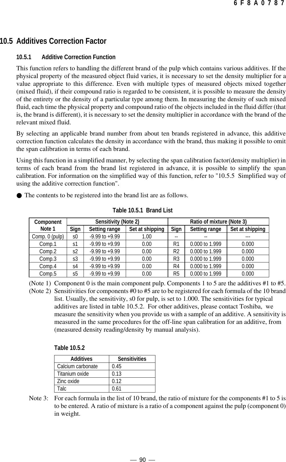
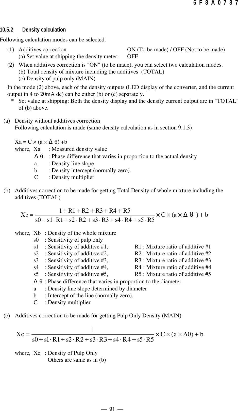
![ 92 6 F 8 A 0 7 8 7(Note) When using the additives correction functions of (b) or (c), set the density multiplier C to 1.000.Following procedure is recommended for making span adjustment. At the beginning of the use ofcorrection, for a whole mixture of a formula, compare the measured density readings you get in drymethod (dry weight) and in manual analysis, and when required, make span adjustment by adjustingthe density multiplier C of the whole mixture.10.5.3 Procedures for using the additives correction functionThe procedure for the additives correction function is described as following steps.Obtain sensitivities of the components Refer to table 10.5.2Select the formula list number for registering (parameters)Set sensitivities of pulp and additives (s0 to s5)Set mixture ratios of additives (R1 to R5)Perform zero point calibration Refer to [6.4 Zero Point Calibration]Set the density multiplier to 1.000Select ON for additives correctionSelect calculation mode for additives correction(TOTAL or MAIN)Select the brand list number that corresponds with the formula(Parameter set)Let the liquid mixture of selected brand flow.Read the density indication(M), and simultaneouslysample the substance to measure.Measure the density (A) of the sample by manual analysisCalculate C as below, then fine adjust C (density multiplier)C=(A/M)×1 (Default value of C is 1)Start measuring DensityYou can set for up to ten formulas. Each of whichcan have up to five additives, to which sensitivitiesand ratios can be entered individually.When brand is changed](https://usermanual.wiki/Toshiba/62372311/User-Guide-231580-Page-94.png)
![ 93 6 F 8 A 0 7 8 710.5.4 How to set the additives correction function(1) Switching to the setting mode (see Subsection 5.2.5)First of all, press the [ESC] key of the converter several times (normally once although this varieswith the operation status) to return to the initial menu display. Next, use the [→] key to move theLCD indicator cursor to the menu number "2" of "2 SETTING MENU" and then press the [SET]key to display the warning message saying "Test output will be valid.". Make sure that there is noproblem and then press [→] to get into the setting mode. To get into [2: SETTING MENU], it isnecessary to further enter the password "8000". Then, the output will be switched to thesimulated output that is set beforehand.(2) Selecting the additives correction menu (see Subsection 5.2.5)Initially, the menu list of the menu numbers 5 to 8 is displayed. Press the [UP] key once to switchto the menu list display of the next menu numbers 9 to 11. Use the [→] key to move the cursor ofthe LCD indicator to the menu number "10" of "10: ADDITIVES CORRECT" and then press the[SET] key to select the menu of "10: ADDITIVES CORRECT".(3) Verifying and changing the various settings for additives correction (see Subsection 5.2.15)(3-1) Selecting the OFF/ON of the additives correction functionVerify the set value of the initial menu "AF: ADDITIVES COMP." of the additivescorrection. "OFF" means that the additives correction function is unavailable, thus notdisplaying the detailed menu concerning the additives correction. When using theadditives correction function, press the [SET] key to switch to the OFF/ON selectiondisplay of the additives correction. Each time the [UP] or [DN] key is pressed, the set valuealternates between "OFF" and "ON". With the value set to "ON", press the [SET] key toverify it. The screen will be returned to the immediately preceding one; make sure that thevalue is correctly reset.(3-2) Selecting a density display (see subsection 10.5.2)Continuing on from (3-1), press the [UP] key to switch to the display of "Ad: DISPLAYDENSITY". In this menu, decide whether the density display should be the density of theentire mixed fluid including the additives "TOTAL" or the density of the pulp only"MAIN". When changing the setting, press the [SET] key to switch to the selected display,use the [UP] or [DN] key to switch between "TOTAL" and "MAIN" and then press the[SET] key at the status to be set.(3-3) Selecting a density display (see Subsection 10.5.2)Continuing on from (3-2), press the [UP] key to switch to the display of "Ac: OUTPUTDENSITY". In this menu, decide whether the density current output of 4 to 20mA shouldbe the density of the entire mixed fluid including the additives (TOTAL) or the density ofthe pulp only (MAIN). When changing the setting, press the [SET] key to switch to theselected display, use the [UP] or [DN] key to switch between "TOTAL" and "MAIN" andthen press the [SET] key at the status to be set.(3-4) Selecting a parameter set number (a brand list number)Continuing on from (3-3), press the [UP] key to switch to the display of "Ap:PARAMETER SET NO.". In this menu, select a parameter set number. Press the [SET]key to switch to the setup display and then input the parameter set number. Use the [→] keyto move to the digit, and use the [UP] or [DN] key to alter the numeric value of the relevantdigit. When entering input is completed, press the [SET] key to confirm it. The screen willbe returned to the immediately preceding one; make sure that the value is correctly reset.](https://usermanual.wiki/Toshiba/62372311/User-Guide-231580-Page-95.png)
![ 94 6 F 8 A 0 7 8 7(3-5) Setting the sensitivity and the compound ratioContinuing on from (3-4), press the [UP] key to switch to the menu of "s0: MAIN OBJSENS." and then, after switching to the setup display by pressing the [SET] key, input thesensitivity of the main object (component 0). Use the [→] key to move to the digit, and usethe [UP] or [DN] key to alter the numeric value of the relevant digit. When entering input iscompleted, press the [SET] key to confirm it. The screen will be returned to theimmediately preceding one; make sure that the value is correctly reset. Continue on toswitch to the next setup menu display with the [UP] key. And, in accordance with the sameprocedure, set the sensitivities s0 to s5 of components (additives) 1 to 5 as well ascompound ratios R1 to R5 of components (additives) 1 to 5.(4) Returning to the measuring modePress the [ESC] key twice to return to the initial menu screen and return to the measuring modefrom the setting mode to resume the normal measurement.10.5.5 Simplified Correction on AdditivesPrevious section describes complete correction on additives in which sensitivities and ratios of mixtureper additive were taken into account in calculation. By using only a sensitivity for the whole mixture (amixture of pulp and additives], the additives correction can be simplified as described below. In thissimplified correction, a density multiplier (sensitivity) is obtained separately for each formula andentered into the list of formula. When a formula is changed, you need to select a new formula number tochange the density mulyiplier to continue measuring density. Up to ten formulas can be entered into thelist.Procedures for a simplified correction is as follows. See the section 10.5.1 to 10.5.3 for basicinformation, and refer to section 10.5.4 Operations for correction.● Procedures for simplified correction of additives.Set the density multiplier C to 1.000Select Calculation Mode for additives correction...No (correction)Perform zero calibration See “6.4 Zero calibration”Carry out span calibration for each brand, and obtain sensitivity as below.Sensitivity = (Measured density reading)/(Density obtained by manual analysis)Enter the sensitivity of a formula into the sensitivity s0 of the component 0 in the formula list.Select (TOTAL)(total density of a mixture, with additives correction] for the calculation modeSelect a brand list number that corresponds with the mixture to be measured.Run the fluid to measure and measure densitySee Note 1When the brand is changed.(Note1) Set all sensitivities and ratios to 0.00 and 0.000 respectively for all of the components 1 to 5.(Or to the default values set at shipping.)](https://usermanual.wiki/Toshiba/62372311/User-Guide-231580-Page-96.png)
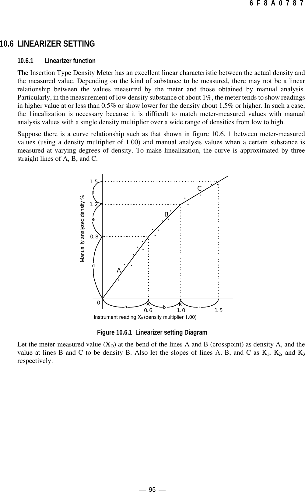
![ 97 6 F 8 A 0 7 8 710.6.2 Linearizer setting(1) Switching to the setting mode (see Subsection 5.2.5)First of all, press the [ESC] key of the converter several times (normally once although this varieswith the operation status) to return to the initial menu display. Next, use the [→] key to move theLCD indicator cursor to the menu number "2" of "2 SETTING MENU" and then press the [SET]key to display the warning message saying "Test output will be valid.". Make sure that there is noproblem and then press [→] to get into the setting mode. To get into [2: SETTING MENU], it isnecessary to further enter the password "8000". Then, the output will be switched to thesimulated output that is set beforehand.(2) Selecting the linearizer menu (see Subsection 5.2.5)Initially, the menu list of the menu numbers 5 to 8 is displayed. Press the [UP] key to switch to themenu list display of the menu numbers 9 to 11. Use the [→] key to move the cursor of the LCDindicator to the menu number "9" of "9: LINEARIZ/CNDUCTVTY" and then press the [SET]key to select the menu of "9: LINEARIZ/CNDUCTVTY".(3) Setting the density and the factor (see Subsection 5.2.14)The setup menus of density and factor are called one after another from the start of the menudevelopment of "9: LINEARIZ/CNDUCTVTY". First of all, press the [SET] key at "LA:DENSITY A" and then, after the setup display of density A is displayed, input the value fordensity A. Use the [→] key to move to the digit, and use the [UP] or [DN] key to alter the numericvalue of the relevant digit. When entering input is completed, press the [SET] key to confirm it.The screen will be returned to the immediately preceding one; make sure that the value iscorrectly reset. Continue on to switch to the next setup menu display with the [UP] key. And, inaccordance with the same procedure, set density B and factors K1, K2 and K3.(4) Returning to the measuring modePress the [ESC] key twice to return to the initial menu screen and return to the measuring modefrom the setting mode to resume the normal measurement.(5) Determining and setting the density multiplierPerform the density measurement after setting the linearizer and, in accordance with the spancalibration in Section 6.5, determine and set the density multiplier C.](https://usermanual.wiki/Toshiba/62372311/User-Guide-231580-Page-99.png)
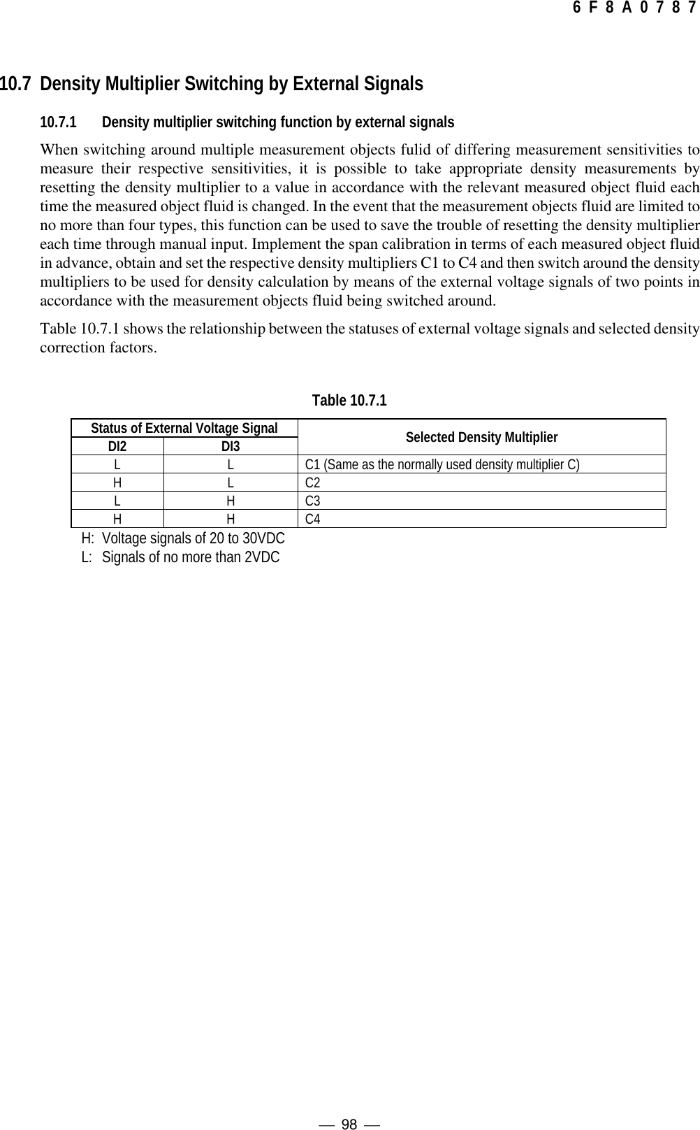
![ 99 6 F 8 A 0 7 8 710.7.2 Setting the density multiplier switching by external signals(1) Switching to the setting mode (see Subsection 5.2.5)First of all, press the [ESC] key of the converter several times (normally once although this varieswith the operation status) to return to the initial menu display. Next, use the [→] key to move theLCD indicator cursor to the menu number "2" of "2 SETTING MENU" and then press the [SET]key to display the warning message saying "Test output will be valid.". Make sure that there is noproblem and then press [→] to get into the setting mode. To get into [2: SETTING MENU], it isnecessary to further enter the password "8000". Then, the output will be switched to thesimulated output that is set beforehand.(2) Selecting the "OTHERS" setting menus (see Subsection 5.2.5)Initially, the menu list of menu numbers 5 to 8 is displayed. However, by pressing the [UP] key,this display is switched to the menu list of the next menu numbers 9 to 11. Use the [→] key tomove the LCD indicator cursor to the menu number "11" of "11: OTHERS" and then press the[SET] key to select the menu of "11: OTHERS."(3) Selecting of density multiplier switching ON/OFF(see Subsection 5.2.16)Press the [UP] key once to display "DI: C CHANGE ON/OFF". Press the [SET] key here toswitch to the setup display. Each time the [UP] or [DN] key is pressed, the set value alternatesbetween "ON" and "OFF". Therefore, when using the function of density multiplier switching byexternal signals, set the value to "ON" and then press the [SET] key to verify it. The screen will bereturned to the immediately preceding one; make sure that the value is correctly reset.(4) Setting density multipliers C2, C3 and C4Continuing on from (3), press the [UP] key once to switch to the display of "C2:DensityMultiplier". Switch to the setup display by pressing the [SET] key here and then input thedensity multiplier C2. Use the [→] key to move to the digit, and use the [UP] or [DN] key to alterthe numeric value of the relevant digit. When entering input is completed, press the [SET] key toconfirm it. The screen will be returned to the immediately preceding one; make sure that the valueis correctly reset. Continue on to switch to the next setup menu display with the [UP] key and setC3 and C4 in accordance with the same procedure. When setting the density multiplier C1, referto "6.5 Span Calibration".(5) Returning to the measuring modePress the [ESC] key twice to return to the initial menu screen and return to the measuring modefrom the setting mode to resume the normal measurement.](https://usermanual.wiki/Toshiba/62372311/User-Guide-231580-Page-101.png)
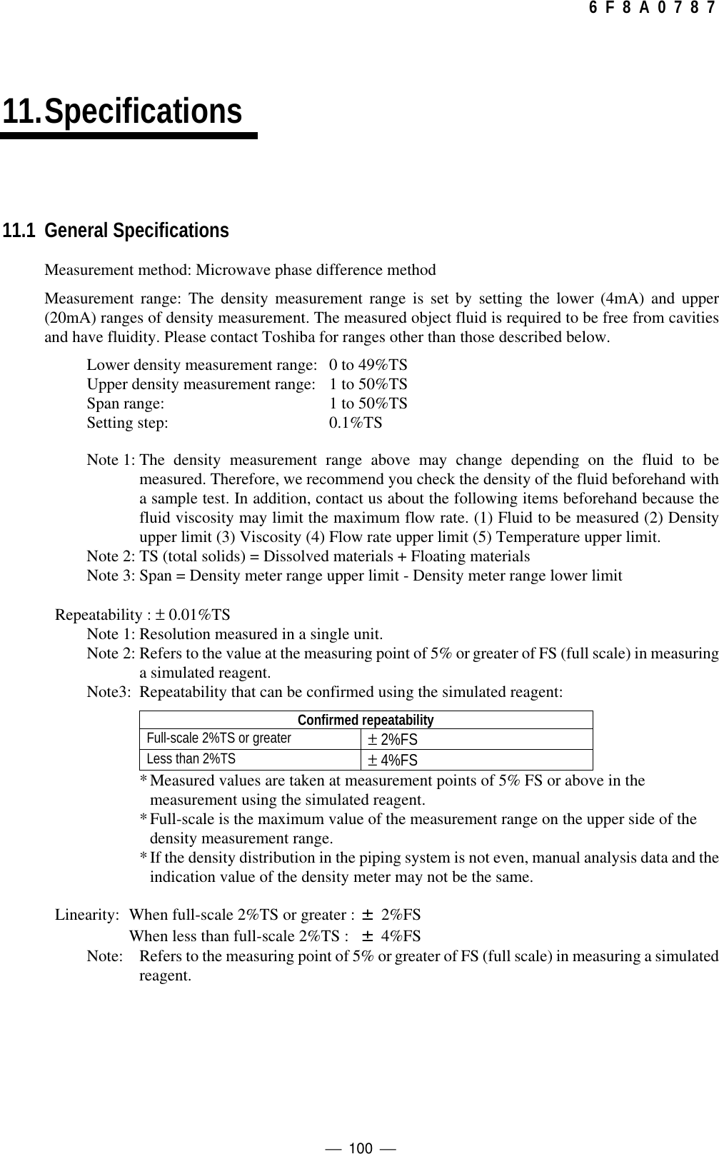
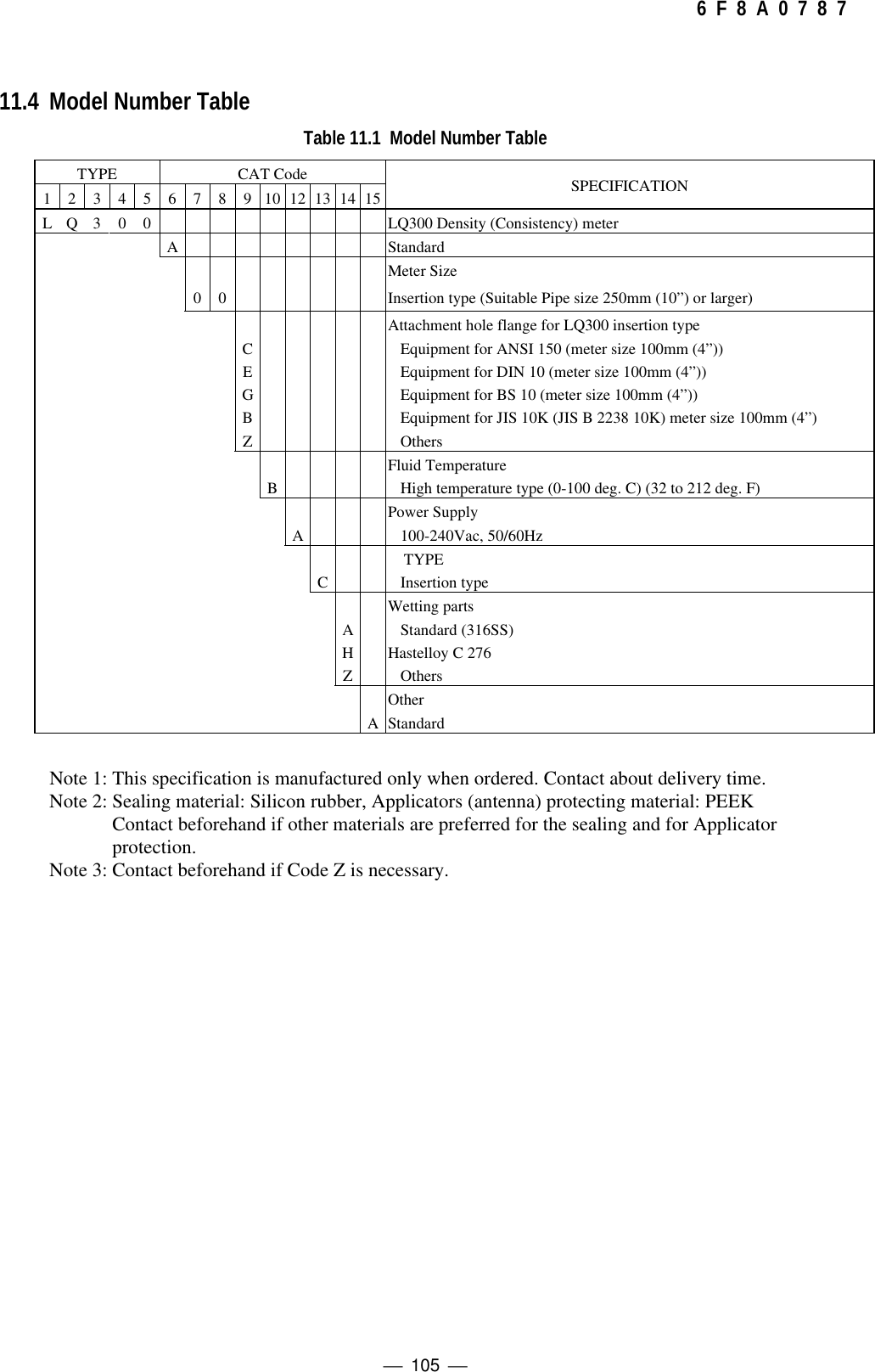
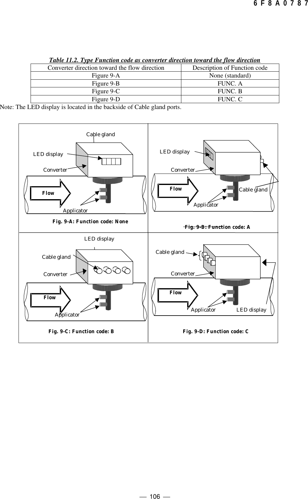
![ 107 6 F 8 A 0 7 8 7AppendixAttached Figure 1.[Unit: mm]231重心位置AA57JIS10K, 100AフランジCenter of gravity position8 - φ 19 holeJIS10K, 100A flange](https://usermanual.wiki/Toshiba/62372311/User-Guide-231580-Page-109.png)