TransCore FCE060 802.11g Compact Flash Module User Manual 1
TransCore 802.11g Compact Flash Module 1
Contents
- 1. User Manual1
- 2. User Manual 2
- 3. User Manual 3
User Manual1
HandHeld Mobile Computer

CMU055-A2a
ISO 9001:2000 Certication5
Introduction6
Intended Use 6
Product Description 6
Product Illustrations6
Product Specications7
Warning / Caution / Note Denition 7
Symbols 8
Quick Tour 10
CE8640B & CE8640BWE Front View 10
CE8810B & CE8810BWE Front View 11
CE8820B & CE8820BWE Front View 12
CE8000B & CE8000BWE Back View 13
CE8000B & CE8000BWE Side View14
Getting Started15
Battery Warnings15
Main Batteries Very Low 15
Main Battery Expired15
Installing the Battery 16
Charging the Battery 17
From the Modular Charger 17
From the Communication Cradle18
From the External Battery Charger 19
Battery Status Indicator Color Denition 20
Operation Guide21
Turning the Unit On & Off 21
Turn Unit On 21
Turn Unit Off Manually21
Turn Off the CE8640B Unit 21
Automatic Shut-Off 22
Touch Screen22
Touch Screen Calibration 22
Using the Touch Screen 23
Using the Keyboard 24
CE8640B24
CE8800B25
Function Keys 26
Virtual Keyboard 26
Using PC Cards28
Inserting PC Cards 28
Removing PC Cards 29
Using SDIO Cards30
Inserting SDIO Cards 30
Removing SDIO Cards 31

CMU055-A2a
IrDA interface (Selected mode) 32
Transferring Files in FTP Mode33
Wireless & BlueTooth Options (BWE versions) 34
Using Wireless34
Using BlueTooth 35
CE8000B Options37
Barcode Readers 38
Laser Scanner38
Testing the Laser Scanner 38
2D Barcode Reader39
Testing the 2D Barcode Reader 39
Advanced Settings 40
Advanced Battery Options40
To See Power Remaining 40
Preserving Power 40
Battery Power Management 40
ActiveSync Communication41
Partnership with Ethernet Cradle42
Advanced User Information44
Companion Programs46
DAP CE8000B Programs46
Microsoft Programs 47
Troubleshooting Guide48
Storage & Maintenance 49
Storage 49
Cleaning49
Shipping the Unit 49
Carrying Strap 49
Battery Maintenance 50
Main Battery 50
Backup Battery 50
Replacing the Battery 50
Touch Screen Maintenance51
Unit with Laser Option 51
Quick-Reference Replacement Parts List 51
Recycling Passport52
CE Conformity 53
FCC Statement, Copyright Policy54
Microsoft End-User License Agreement55
Warranty56
International Addresses 57

CMU055-A2a
DAP Technologies has documented and implemented a Quality Management System in accordance with ISO
9001:2000 International Standard (Certicate number: 95786)
This International recognition has been made possible thanks to the continual efforts put forth by DAP’s
Personnel
In order to ensure continuous improvements to our products and services, we invite you to communicate your
comments to our Customer Service Department by dialing:
1 (418) 681-9394 or 1 (800) 363-1993
1(800) 363-1993
+ (800) 8899 1000
or
CMU055-A2a
INTENDED USE
This User Guide is intended to assist in the operation of the CE8000B series and applies to the CE8640B,
CE8800B & CE8820B running Windows CENET 50 Operating System, Release Pack P or later and manufac-
tured after May 1st, 2009 Should any information in this Guide be incorrect, please report your comments to your
local Customer Service Representative nearest you so that this document can be made as accurate as possible
For optimal use of this User Guide in electronic format, we recommend Acrobat Adobe Reader version
60 and higher
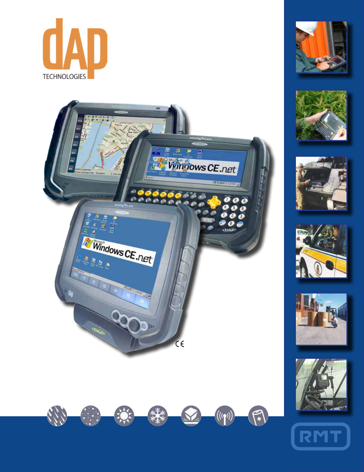
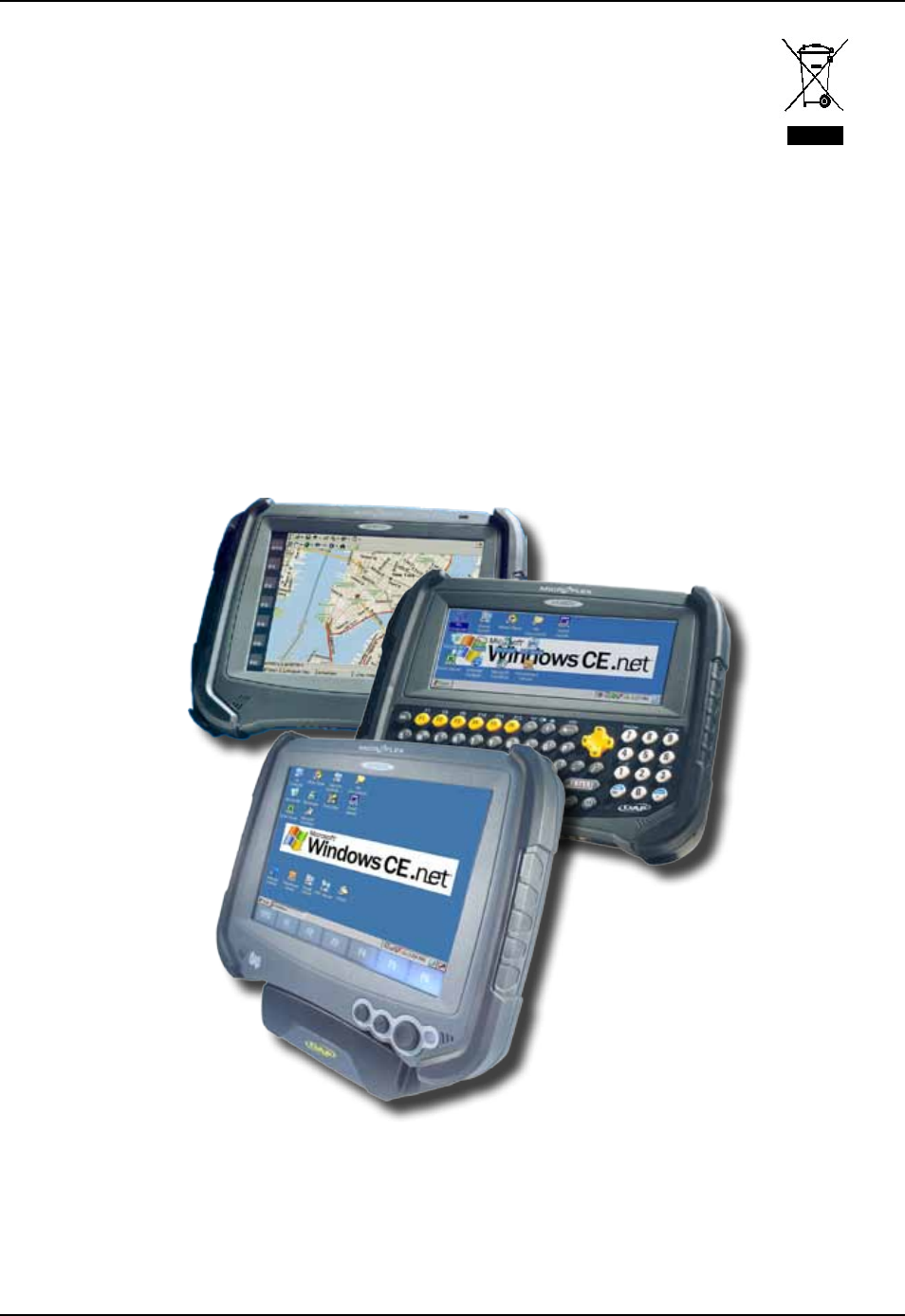
PRODUCT DESCRIPTION
The CE8000B Series is built for use in all environments It will survive being dropped, being subject to vibra-
tion, being used in below freezing conditions or desert heat, making it the ideal work tool for industry type
applications within many market segments
The BWE version includes WLAN radio 80211b/g and Bluetooth
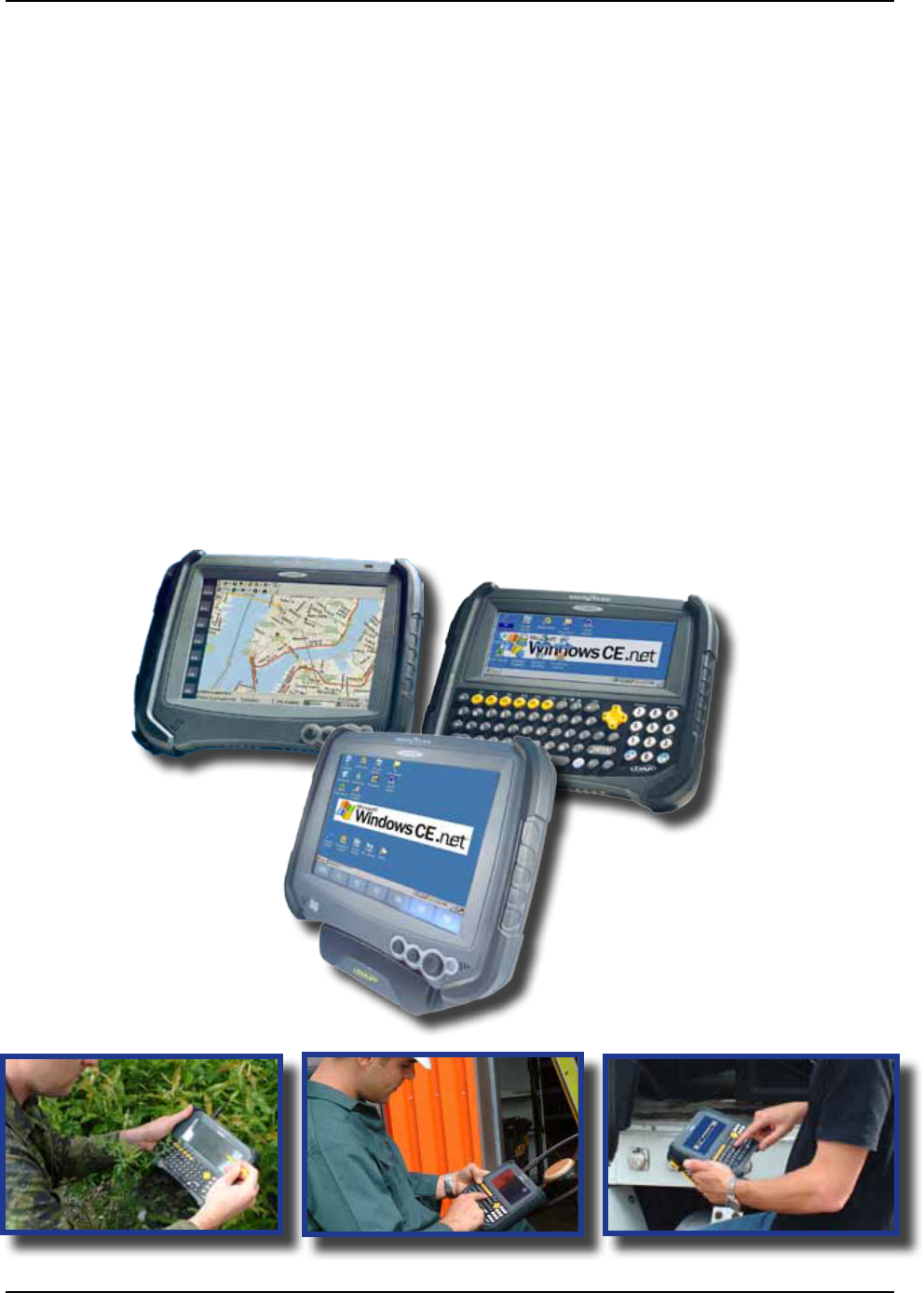
PRODUCT ILLUSTRATIONS
CE8810B
CE8640B
CE8820B

CMU055-A2a
For current product specications, please contact DAP Technologies, or visit our web site
The words WARNING, CAUTION, and NOTE carry special meanings and should be carefully reviewed
Alerts the reader about a situation, which if not avoided, could affect the proper functioning of the unit and
result in permanent damage to the unit
Alerts the reader of a potentially hazardous situation, which if not avoided, may result in minor injury to the
user or may cause damage to the equipment This includes special care necessary for the safe and effective
use of the device and the care necessary to avoid any damage that may occur as a result of use or misuse
This provides special information to make important instructions clearer
PRODUCT SPECIFICATIONS
CMU055-A2a
Warning or Caution, pay special attention when this symbol is present
In accordance with European Directive 2002/96/EC on Waste Electrical and Electronic
Equipment (WEEE), this symbol indicates that the product must not be disposed of as unsorted
municipal waste, but should be collected separately Refer to your local distributor for return
and/or collection systems available in your country
Caution must be used when this symbol is present This symbol indicates a danger for laser
radiation
CMU055-A2a
• Refer to this Guide when inserting or removing batteries, cables or external peripherals
• Operate and store your DAP unit within the temperature limits specied in this Guide
• Do not use any pointed objects on the keyboard, door or mechanisms Doing so may damage the unit
• Use the ‘Stylus’ which has been provided with the unit by Roper Mobile, as it has been designed with a
non-abrasive material that cannot scratch or deteriorate the touch screen
• Never expose the battery to extreme heat or dispose of by burning
• Any attempts to open the case of a CE8000B unit will void the warranty
• If you need to use a cable other than the ones provided or recommended by
DAP Technologies, we recommend that you contact your Customer Service Representative nearest you
For CE8000B units with the Summit WLAN adapter:
• Depending upon the conguration of your unit, it may have the additional Summit Wireless area network
(WLAN) adapter Should it be the case, the device will own a FCC ID #T5MFCE060 The FCC number is
located at the back of the unit
• To comply with the FCC and other national RF exposure requirements, a device with a Summit WLAN
adapter should be kept at a minimum distance of 20 cm from any body parts, except for hands, wrists,
feet and ankles
For CE8000B units with the Laser Scanner Option:
- Laser radiation emitted from laser scanner Do not look directly into the laser light
beam
CMU055-A2a
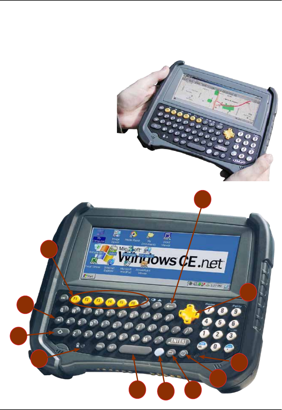
CE8640B & CE8640BWE FRONT VIEW
1 Function Keys (F1 to F6)
2 Backspace Key
3 Navigation Key (Left, Right Top & Bottom)
4 Laser Led
5 ON/OFF Key
6 Folder Key
7 Blue Function Key
8 Space Key
9 Tab Key
10 Shift Key
11 Battery Status LED Indicator
1
2
3
5
876
9
10
AZERTY Keyboard
QWERTY Keyboard
11 4
CMU055-A2a
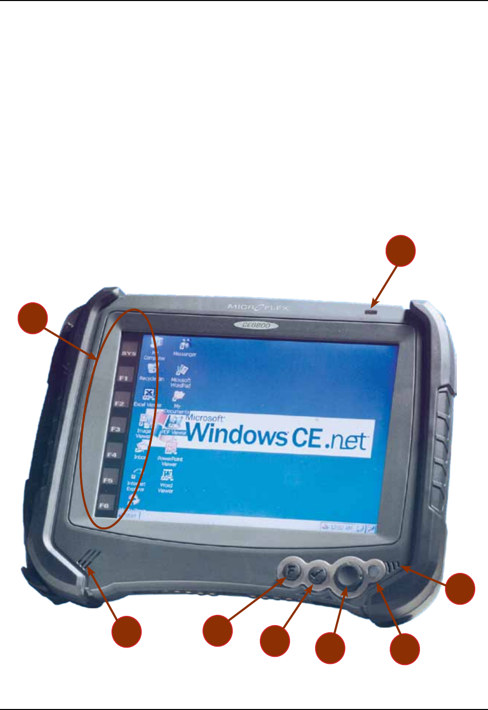
CE8810B & CE8810BWE FRONT VIEW
1 Light Sensor
2 Microphone
3 Battery Status Indicator
4 Navigation Key (Left, Right, Top & Bottom)
5 Enter Key
6 Function Key
7 Speaker
8 Function Keys
2
4
53
6
7
1
8
CMU055-A2a
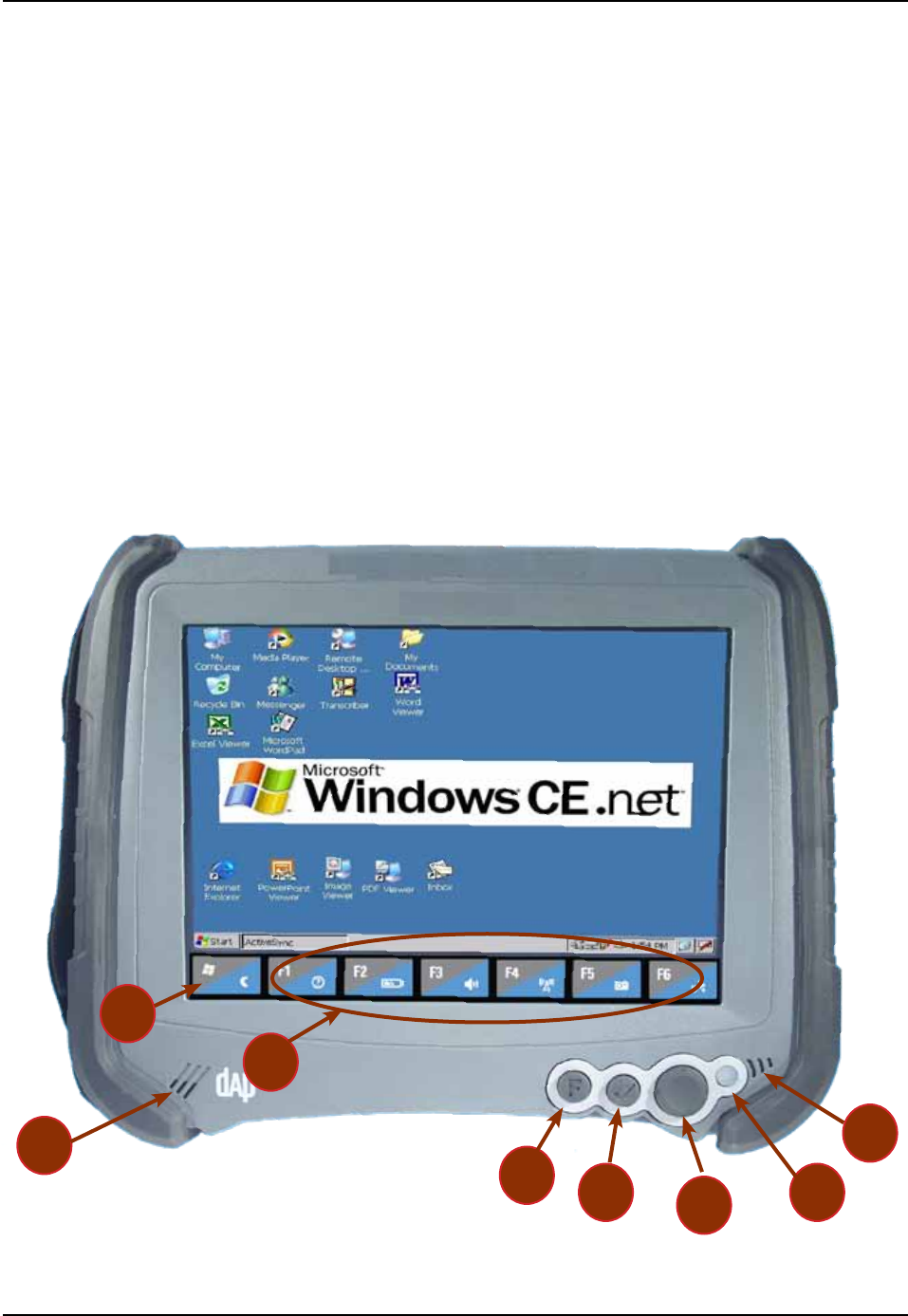
1
2
3
4
7
6
5
8
CE8820B & CE8820BWE FRONT VIEW
1 Microphone
2 Battery Status Indicator
3 Navigation Key (Left, Right, Top & Bottom)
4 Enter Key
5 Function Key
6 Speaker
7 Function Keys
8 Access to System Key
CMU055-A2a
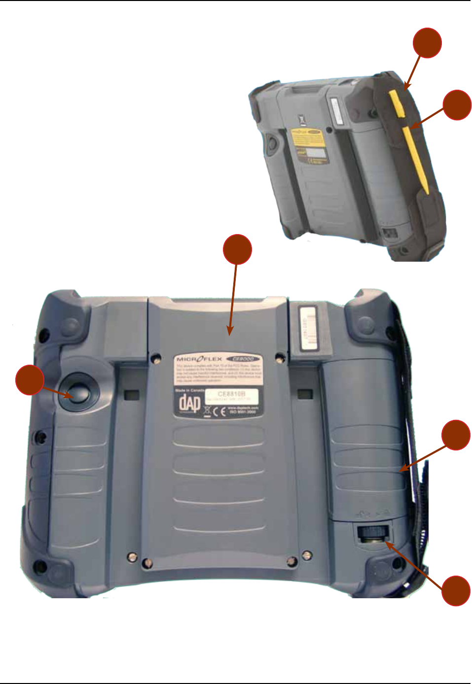
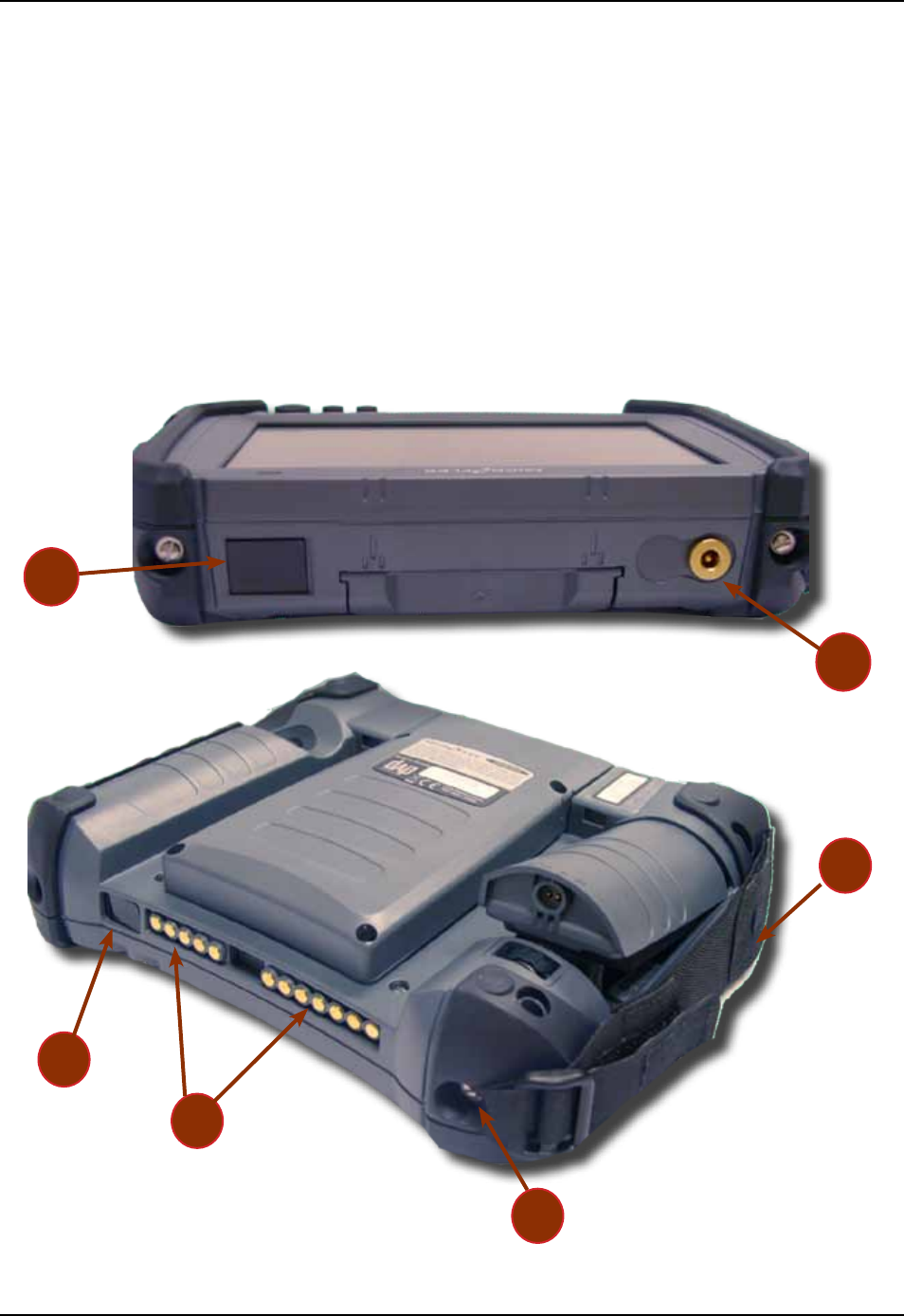
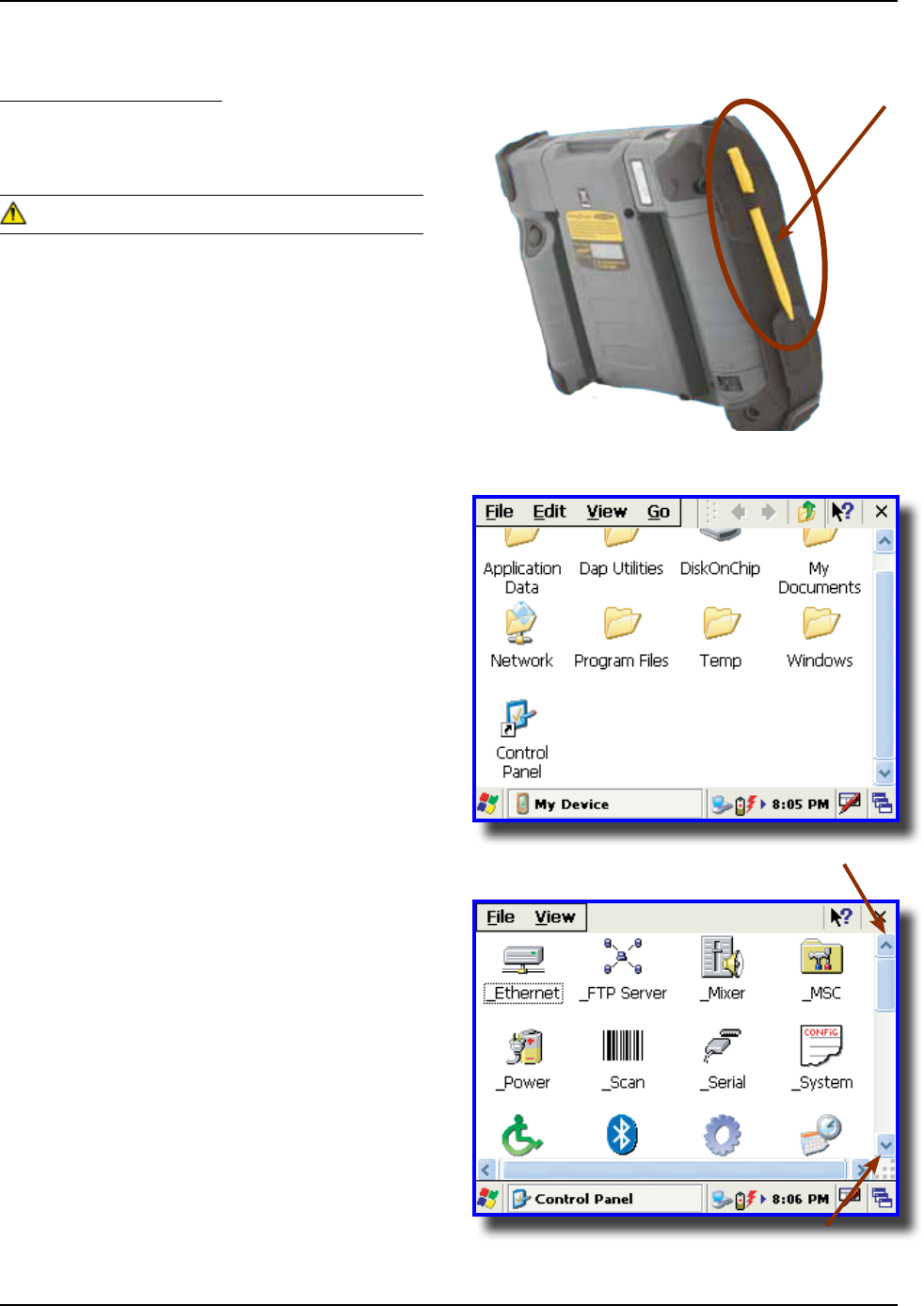
CE8000B & CE8000BWE BACK VIEW
1 Carrying Strap
2 Stylus (Pen)
3 PCMCIA Expansion Bay
4 Release Screw for Battery Compartment
5 Battery Compartment
6 Laser Trigger Button
2
1
4
3
5
6
CMU055-A2a
CE8000B & CE8000BWE SIDE VIEW
1 RJ45 for Ethernet Connection; or 1D/2D BarcodeScanner; or Laser Scanner
2 Charging Connector
3 Carrying Strap
4 Carrying Strap Fastener (available on both sides of the unit)
5 Charging Connectors When Inserted in Cradle
6 IrDA Port (selected model)
3
6
5
4
2
1
CMU055-A2a
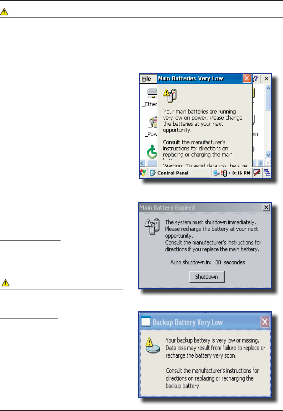
BATTERY WARNINGS
Main Batteries Very Low
Following several hours of use or storage, the
main battery will become very low and this
will appear when there is still some
power remaining
At 5% the battery status indicator continues
to ash and a window will display to indicate
to the user that the battery is at a critical level
and must be re-charged This warning shall be
displayed approximately every 4 minutes for as
long as the battery is below 5 %
It is strongly recommended that the
batteries be re-charged immediately to avoid
loss of data
The level at which this warning is
to appear can be congured according
to preference Refer to
for further instructions
Main Battery Expired
This warning will appear when the power is too
low Turn the unit off immediately and recharge
the batteries
Data may be lost if the unit is not re-charged
immediately
Backup Battery Low
The backup battery will save programs and
les in the memory for days The backup
battery is used when replacing the main
battery or when the main battery has expired
The backup battery will be re-charged
every time the main batteries are charged
• The residual power of the main battery
• The amount of memory installed in the
unit
Upon receiving your CE8000B unit, it is strongly recommended that you rst charge the batteries prior to use
These following messages are likely to appear due to the length of time the unit was stored When the battery
reaches the low level, the battery status indicator will ash red The Main Battery eld will be highlighted as
“Low” under the Battery or Status Tab It will remain highlighted as long as the battery level is between 6%
and 16%
CMU055-A2a
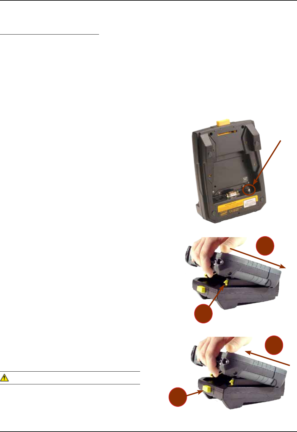
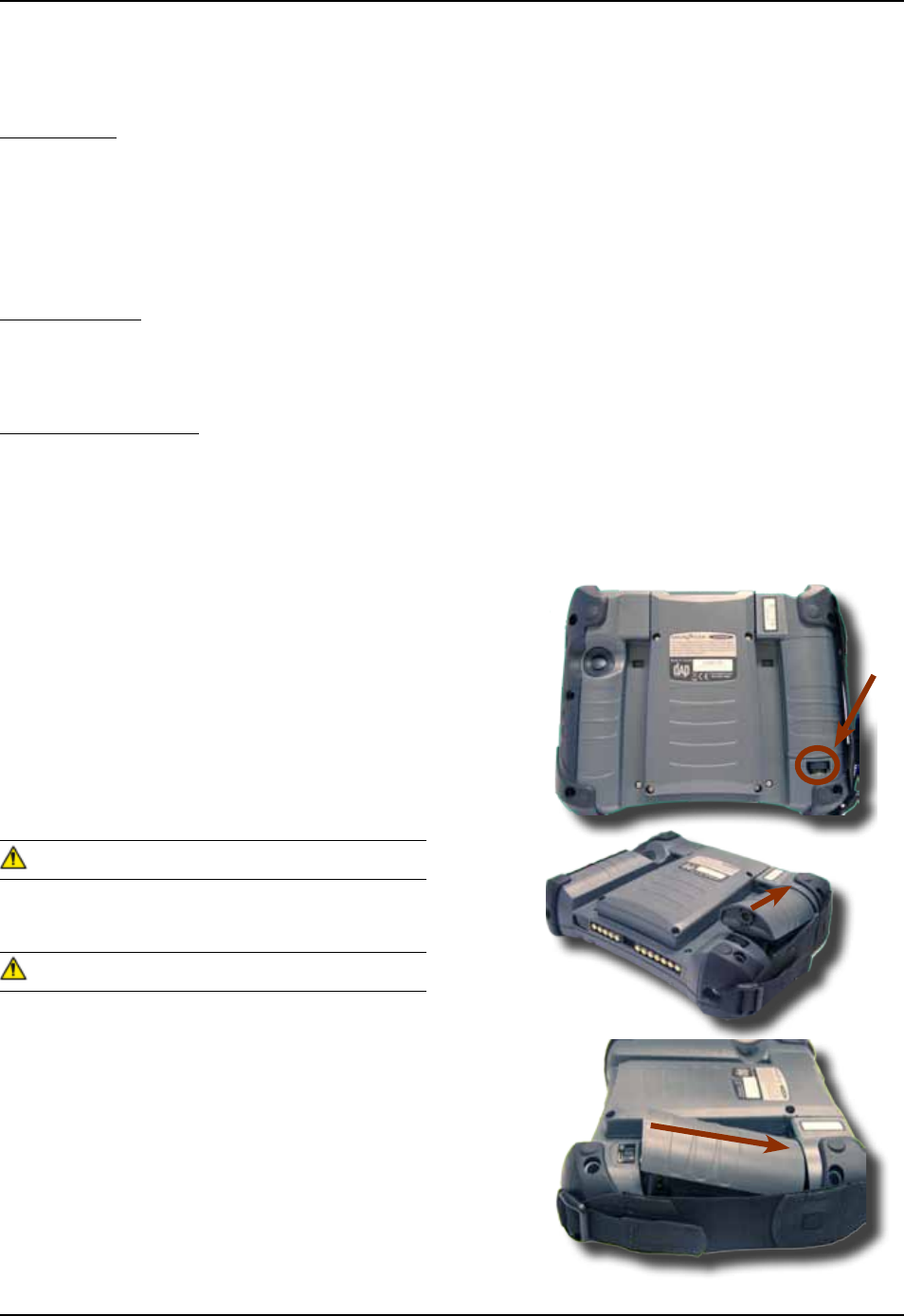
INSTALLING THE BATTERY
All CE8000B units are delivered with battery
not installed Install battery prior to charging the
unit
1 Place the battery in the compartment
located at the back of the unit
2 Turn to lock battery pack into position
It battery pack is not locked into position, unit will
not start even if charger is connected to the unit
A warning will display indicating to the user to
lock battery pack securely into position
CMU055-A2a
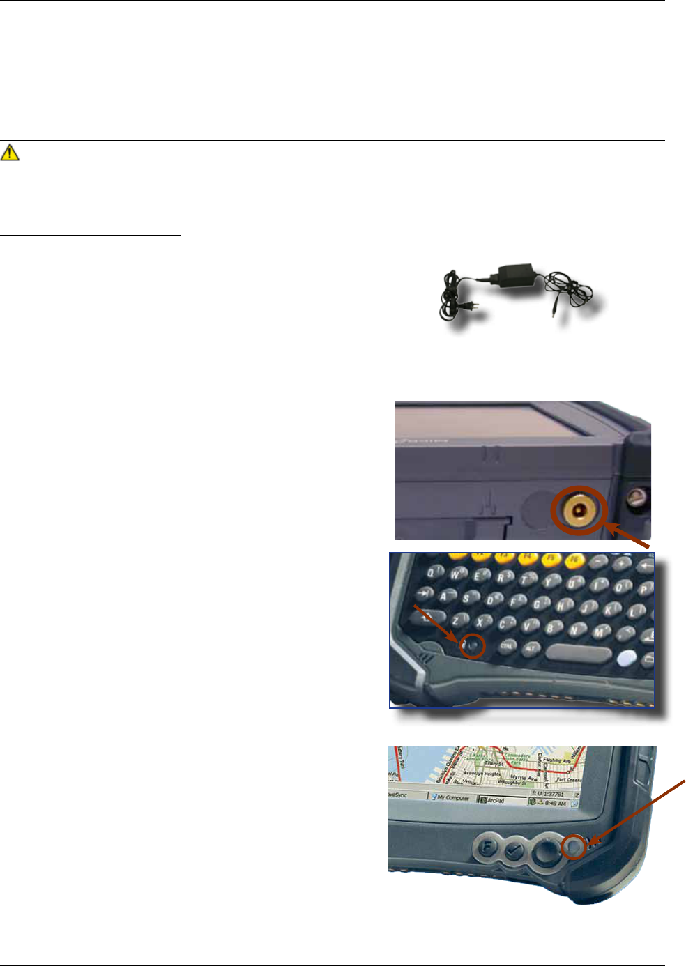
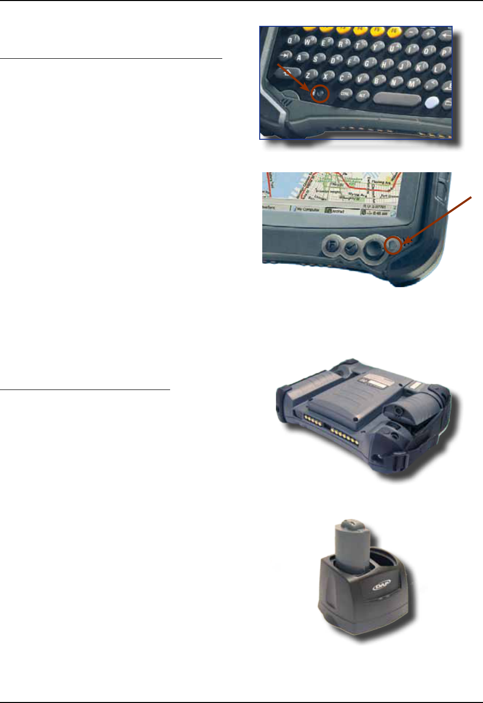
CHARGING THE BATTERY
From the Modular Charger
1 Charging with Modular Charger requires one of
the following Modular Chargers for your area:
CSCE300-NA (North America - 110 V / 120 V
AC Adapter) or the CSCE300-EU (Europe 220
V) or the CSCE300-UK (United Kingdom 220 V)
2 Insert connector to unit
3 Connect the Modular Charger to the wall outlet
The CE8000B Battery Status indicator will turn
red in the next 5 seconds indicating that charging
is now in progress The light will turn green when
charging is complete Charging may take up to 5
hours
: If the unit was turned off, it should turn back
on after a few seconds or after 2 to 3 minutes if the
main battery charge has been very low for some
time Processing will resume exactly where it was
interrupted once re-charging starts
To preserve battery integrity, recharging must only take place when the battery is at a temperature
between +5C (41F) to + 45C (113F) The battery status indicator glows yellow if the battery is too hot or
too cold to be charged and the charging system is disabled
Never recharge the unit with the battery removed The unit may reset and can potentially corrupt any unsaved
data
CSCE300-NA
CSCE300-EU
CSCE300-UK
Battery Status indicator on CE8640B
Battery Status indicator on CE8800B
CMU055-A2a
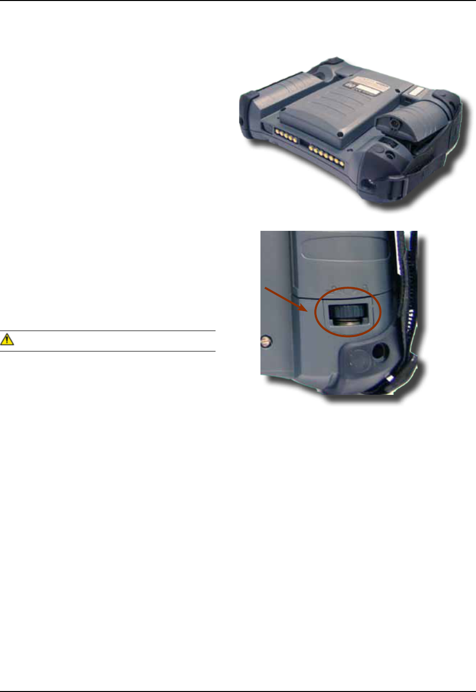
From the Communication Cradle
1 Cradles are available for ofce and vehicle
use The installation requires a Modular
Charger available from DAP Technologies
2 Before charging the CE8000B unit, you must
rst power up the Communication Cradle
3 Insert the round connector of the Modular
Charger into the round connector of the cradle
4 Connect the Modular Charger to the wall outlet
5 Slide unit into the cradle, bottom rst (The
unit will be rmly held into place by the yel-
low hooks located at the top of the cradle )
6 Once charging is complete, remove the unit by
pushing the yellow release button
7 Slide unit upwards to remove
Ensure unit is inserted correctly onto cradle or
charging will not occur and charging pins could be
damaged
CHARGING THE BATTERY (CONTINUED)
Modular Charger
for Cradles
CSCE800-NA
CSCE800-EU
CSCE800-UK
Modular Charger for
Cradles
1) CS512 with a 240
cm (95 in) power cable
a
b
b
a
CMU055-A2a
From the Communication Cradle (Continued)
CHARGING THE BATTERY (CONTINUED)
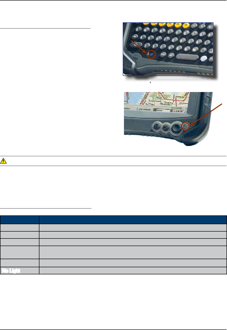
Battery Status indicator on CE8640B
Battery Status indicator on CE8800B
The CE8000B Battery Status indicator will turn
red in the next 5 seconds indicating that charging
is now in progress The light will turn green when
charging is complete Charging may take up to 5
hours
: If the unit was turned off, it should turn back
on after a few seconds or after 2 to 3 minutes if
the main battery charge has been very low for
some time Processing will resume exactly where it
was interrupted once re-charging starts For more
information on the installation and use of the cradle,
refer to the CBCE840 User Guide
From the External Battery Charger
1 You may also use the External Battery
Charger to charge the battery Remove
the main battery from the CE8000B unit
2 Insert battery into charger
3 Power up the charger using the appropriate AC/
DC adapter The charge indicator (LED) will be
red indicating that the battery is charging The
LED will turn green after approximately 5 hours
indicating a full charge
CMU055-A2a
Charger is connected and charging
Battery is fully charged
Warning, low battery
Charger detected, but the battery charger temperature is too high or too
low to re-charge Charge will start when temperature is adequate
Charging disabled by the application program
No Light Power from the charger is not detected
From the External Charger (Continued)
CHARGING THE BATTERY (CONTINUED)
The CE8000B Battery Status indicator
will turn red in the next 5 seconds indicating that
charging is now in progress The light will turn
green when charging is complete Charging may
take up to 5 hours
If the unit was turned off, it should turn back
on after a few seconds or after 2 to 3 minutes if the
main battery charge has been very low for some
time Processing will resume exactly where it was
interrupted once re-charging starts
If the charge indicator (LED) ashes, a problem has occurred during the charging or the battery temperature
has exceeded its safe charging range of +5C (41F) to + 45C (113F) Remove the battery from the charger,
disconnect the charger for 5 to 10 seconds to remove the error status and try charging again (If the problem
persists, contact a Customer Service Representative nearest you)
Battery Status indicator on CE8640B
Battery Status indicator on CE8800B
Battery Status Indicator Color Denition
CMU055-A2a
Once charging is complete, the unit will automati-
cally turn itself off after approximately 3 minutes
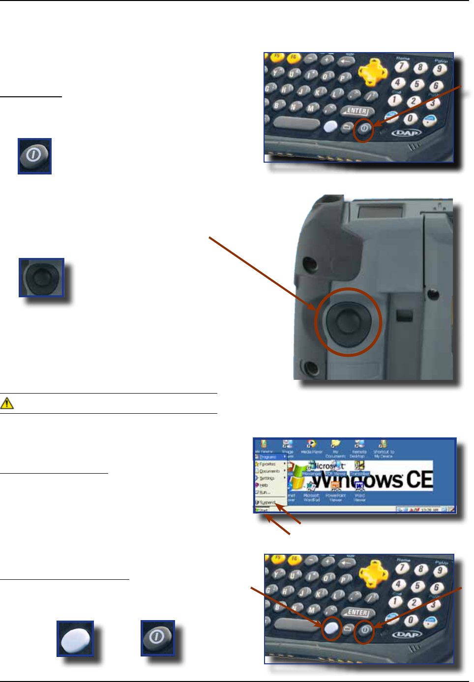
Turn Unit On
1 To turn on the CE8640B unit, press on
the ON button for about 2 to 3 seconds
2 To turn on the CE8810B or the CE8820B
Press the ON key located at the back of the
unit
This key has two (2) functions:
1) To turn the unit ON
2) To use Scanner (Laser Scanner Key)
If the battery power level is very low, it may not be
possible to turn the unit on Ensure battery is fully
charged
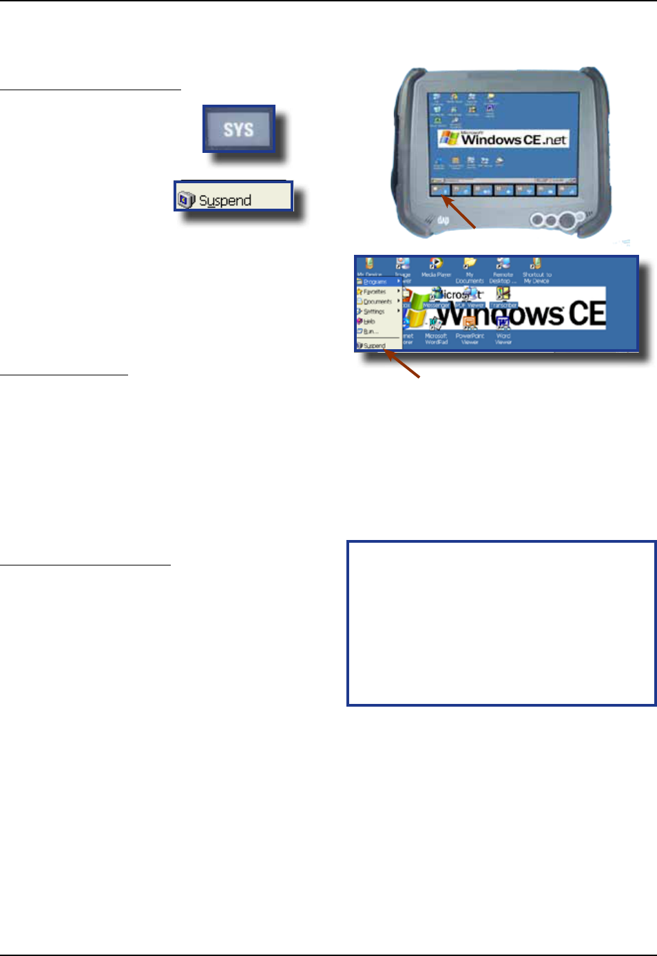
Turn Unit Off Manually
1 Click on the Start Button located at the
bottom left corner of your screen
2 Click suspend
This above instruction is valid for the entire
CE8000B series
Turn Off the CE8640B Unit
1 Click on the blue key followed by the ON/OFF
key; one after the other
TURNING THE UNIT ON & OFF
+
CMU055-A2a
TOUCH SCREEN
Touch Screen Calibration
1 Hold your Stylus down until the Cross begins
to move
2 Touch the center of the Cross for a few
seconds Repeat operation as Cross moves to
another location
To access Touch Screen Calibration
Menu on the CE8640:
1 Click on:
a) Start
b) Settings
c) Control Panel
2 Select Stylus Applet
3 Click on Calibration Tab and click on
Recalibrate
Turn Off the CE8800B Unit
1 Click on the key
2 Click on Suspend
TURNING THE UNIT ON & OFF (CONTINUED)
Automatic Shut-Off
If the unit remains inactive for more than 3 minutes, it will turn off automatically in order to save battery The
unit will also save the exact status of your application program and data before shutting sown Simply restart
the unit when ready to resume your task where you left off
When turned off with fully charged batteries, the unit can be stored up to several days without re-
charging Refer to ‘Storage & Maintenance’ Section for further instructions
+
Carefully press and briey hold stylus
on the center of the target Repeat as
the target moves around the screen
Press the Esc key to cancel
CMU055-A2a
Using the Touch Screen
1 To use the touch screen, simply use
the Stylus provided with the Unit
Apply normal pressure when using the Touch
Screen Excessive pressure may permanently
damage the screen and hinder performance
1 By using the Stylus provided, move les or
folders by “dragging and dropping” into the
folder of your choice
2 To open a folder, double click with Stylus on
the desired folder
3 To run a program, double click with Stylus on
the desired program
4 To see more objects, use Stylus to slide scroll
bar up or down, or click on the up or down
arrows from the scroll bar
TOUCH SCREEN (CONTINUED)
CMU055-A2a
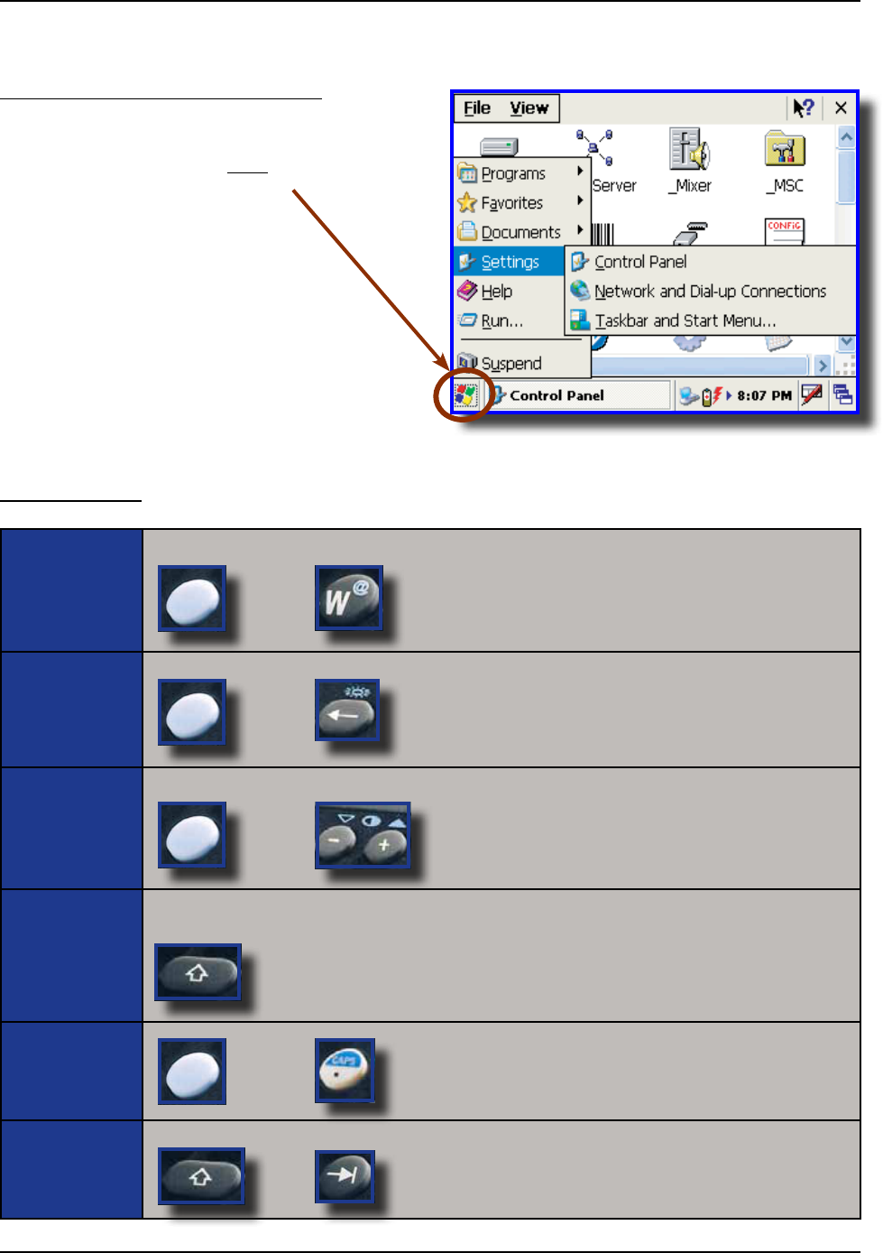
USING THE KEYBOARD
CE8640B & BW
Press the blue key followed by the desired character eg: Pressing the blue key + W will generate the “@”
Press the blue key followed by the backspace key; this will turn on the keyboard backlight
Press the blue key followed by the + or - (plus or minus) to adjust contrast
Press the shift key followed by any letter to generate an upper case letter If CAPS Lock is on, this will then
generate a lower case letter Note: Letters are set by default at lower case
Press Shift followed by the Tab Key
5 To display additional programs or access
Control Panel, go to the Button located
at the bottom left of the screen
TOUCH SCREEN (CONTINUED)
Using the Touch Screen (Continued)
+
+
+
+Letter
+
+
CMU055-A2a
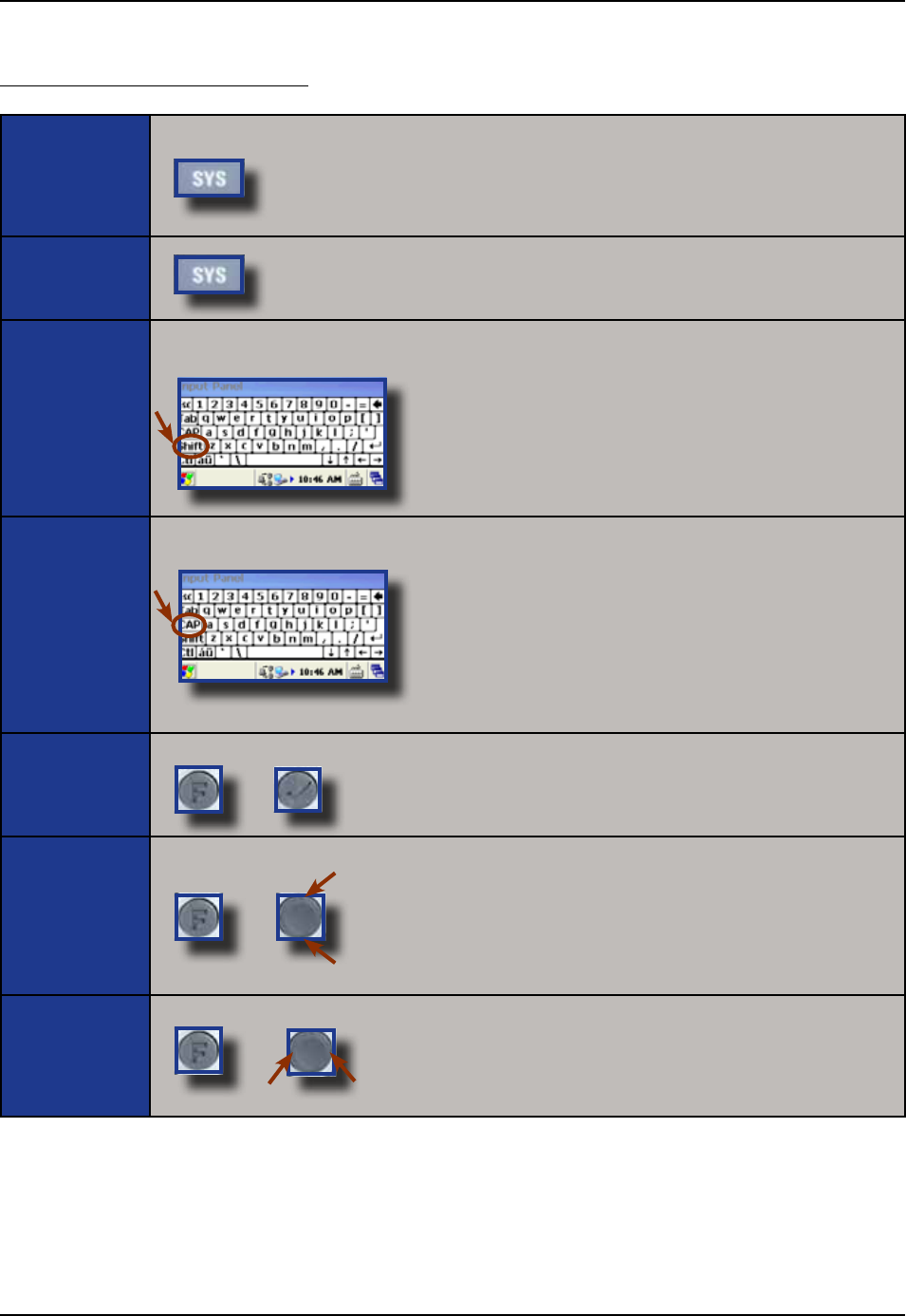
USING THE KEYBOARD (CONTINUED)
CE8810B & BW, CE8820B & BW
Press the System Key (SYS) to access the system applet and adjust backlighting
Using the virtual keyboard, press the shift key followed by any letter to generate an upper case letter If CAPS
Lock is on, this will then generate a lower case letter Note: Letters are set by default at lower case
Using the virtual keyboard, press the “CAP” key for Caps lock function All letters will then be written in Upper
case
Press the Function key followed by the Enter key
To add a space, press the Function key followed by the lower side of the navigation key
To use backspace, press the Function key followed by the upper side of the navigation key
To use tab, press the Function key followed by the right side of the navigation key
To use a back tab, press the Function key followed by the left side of the navigation key
+
+
Backspace
Space
+
CMU055-A2a
Function Keys
Function Keys are used to directly access specic functions to the application being used in unit
F1 Function is set by default to call “Activsync” communication No other Function keys have
been pre-programmed These functions are to be congured by the system administrator for
use with client’s own application
Other functions may also be programmed and may be available through the virtual
keyboard Shift F1 to F6 and CTRL F1 to F6; refer to your system administrator
or DAP Technologies Customer Service Team for more information on
programming these keys
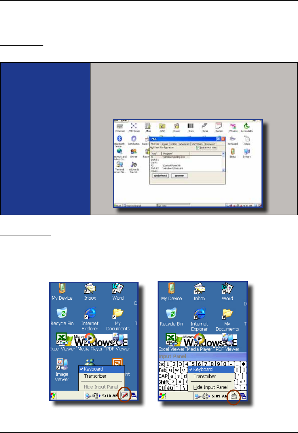
Virtual Keyboard
The virtual keyboard has been included to assist in the entry of data By clicking the Keyboard icon at the
bottom right of the Task Bar, the virtual keyboard will be displayed on the screen
• Selectto hide the Virtual Keyboard
USING THE KEYBOARD (CONTINUED)
CMU055-A2a
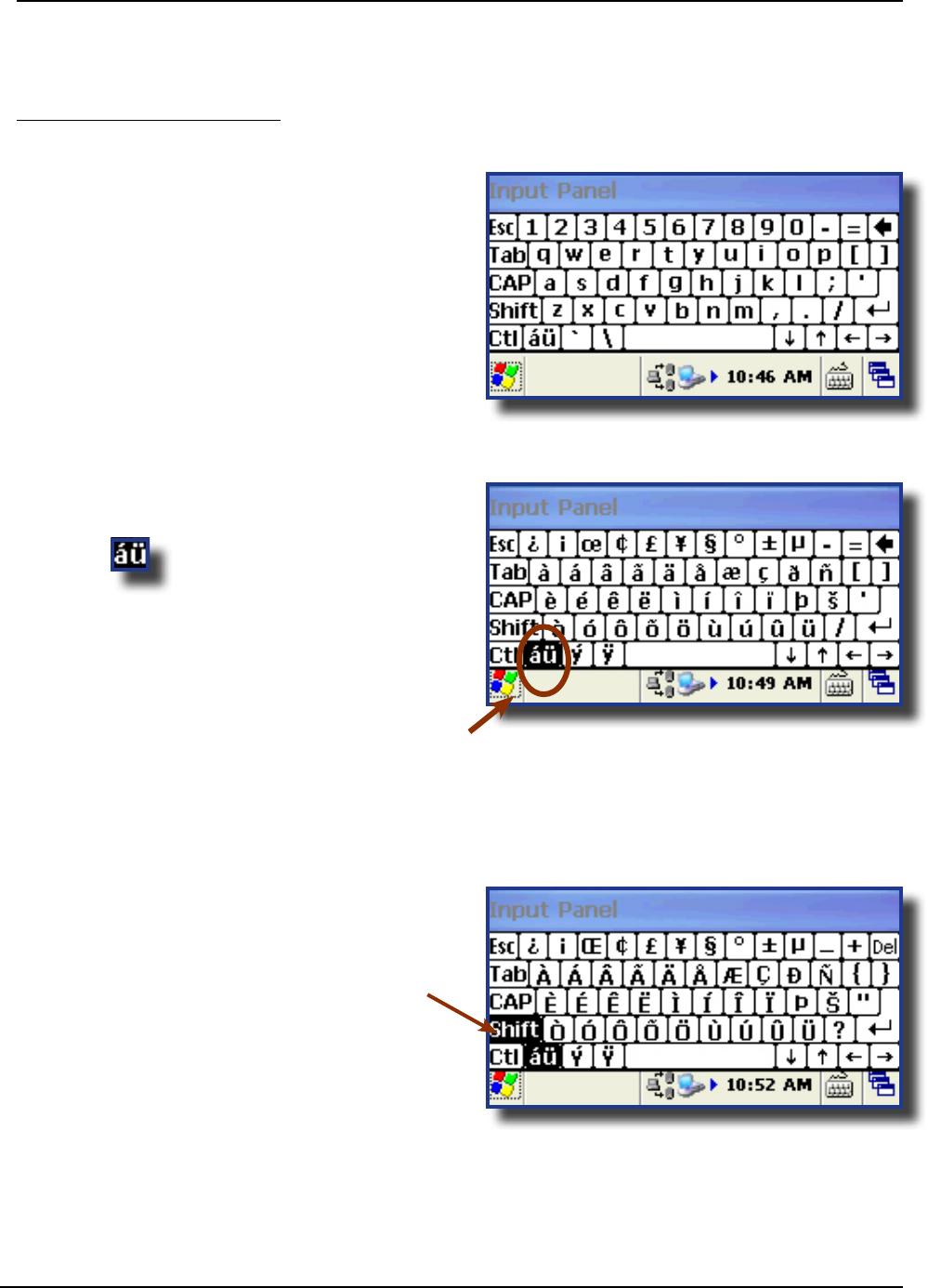
USING THE KEYBOARD (CONTINUED)
Virtual Keyboard (Continued)
1 Standard Keyboard
2 Press to toggle between the
standard and extended language Keyboard
3 Press the Key on the virtual Keyboard to
access additional characters
CMU055-A2a
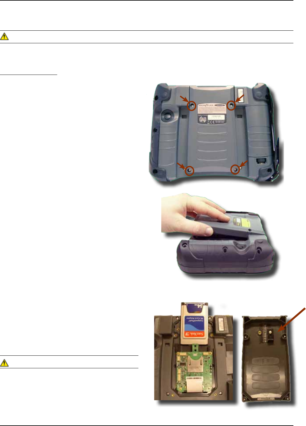
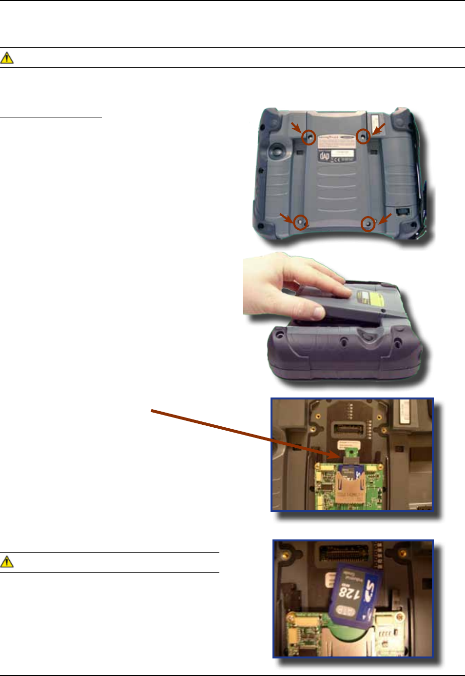
Inserting PC Cards
1 Turn the unit off
2 Using a Flathead Screwdriver remove the four
screws located on either side of the PC Card
Expansion Bay
3 Remove Expansion Bay
4 To insert a PC Card, slide it gently into the
socket Once inserted completely, the PC
Card will lock into place (you will hear a
‘click’) and the release button will pop up
5 Turn stopper to secure PC Card rmly into
place
6 Replace the door to its original position and
tighten screws
• Ensure to place PC Card as indicated on the
right or you may damage the unit or PC Card
• Insert PC Card in a clean and dry environment to
ensure no dust particles or water enters the unit
USING PC CARDS
The Application may not allow the insertion of a PC Card while it is running Refer to your
Supervisor, the application provider or a DAP Technologies Representative for further instructions
CMU055-A2a
1 Turn the unit off
2 Using a Flathead Screwdriver remove the four
screws located on either side of the PC Card
Expansion Bay
3 Remove Expansion Bay
4 Press the located to the right
of the PC Card opening
5 Remove PC Card
6 Replace Expansion Bay and tighten screws
• Remove PC Card in a clean and dry
environment to ensure no dust particles or
water enters the unit
USING PC CARDS (CONTINUED)
Removing PC Cards
The Application may not allow the removal of a PC Card while it is running Refer to your
Supervisor, the application provider or a DAP Technologies Representative for further instructions
CMU055-A2a
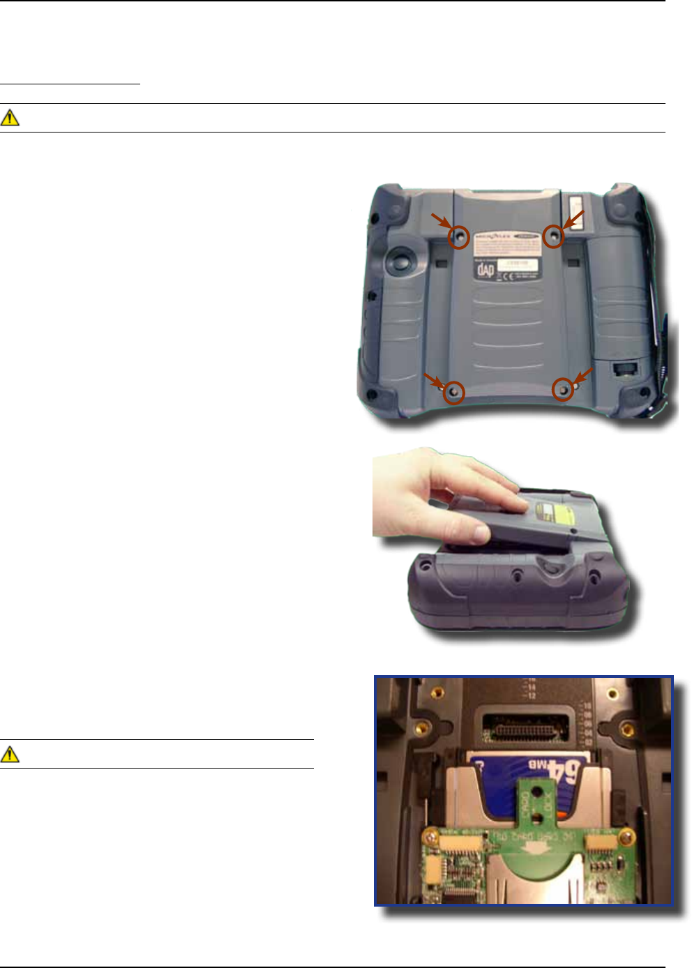
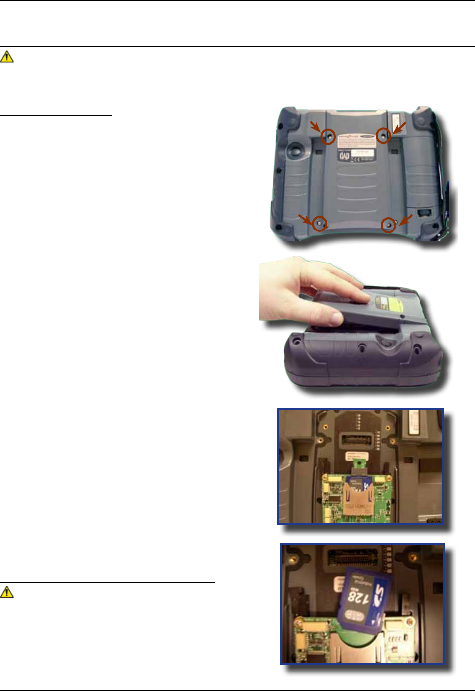
Inserting SDIO Cards
1 Turn the unit off
2 Using a Flathead Screwdriver remove the four
screws located on either side of the PC Card
Expansion Bay
3 Remove Expansion Bay
4 Remove the stopper
5 To insert a SDIO Card, slide it gently into the
socket Once inserted completely, the SDIO
Card will lock into place
6 Place stopper to secure SDIO Card rmly into
place
7 Replace the door to its original position and
tighten screws
• Ensure to place SDIO Card as indicated on the
right or you may damage the unit or PC Card
• Insert SDIO Card in a clean and dry environment
to ensure no dust particles or water enters the unit
USING SDIO CARDS
The Application may not allow the insertion of an SDIO Card while it is running Refer to your
Supervisor, the application provider or a DAP Technologies Representative for further instructions
CMU055-A2a
1 Turn the unit off
2 Using a Flathead Screwdriver remove the
four screws located on either side of the
SDIO Card Expansion Bay
3 Remove Expansion Bay
4 Remove stopper
5 Remove SDIO Card
6 Replace Expansion Bay and tighten screws
7 Re-install stopper
• Remove SDIO Cards in a clean and dry
environment to ensure no dust particles or
water enters the unit
USING SDIO CARDS (CONTINUED)
The Application may not allow the removal of an SDIO Card while it is running Refer to your Supervisor, the
application provider or a DAP Technologies Representative for further instructions
Removing SDIO Cards
CMU055-A2a
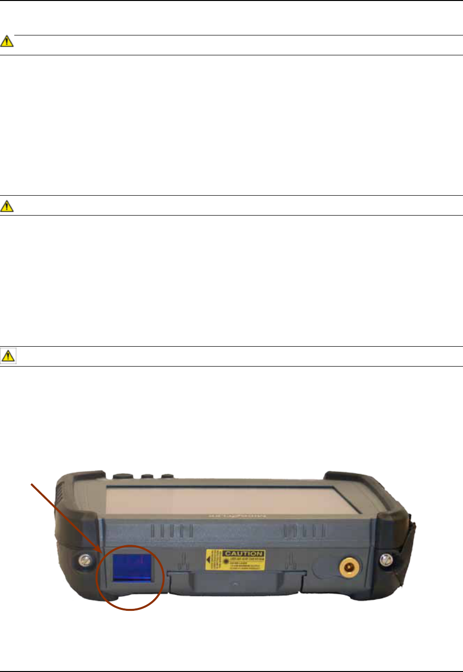
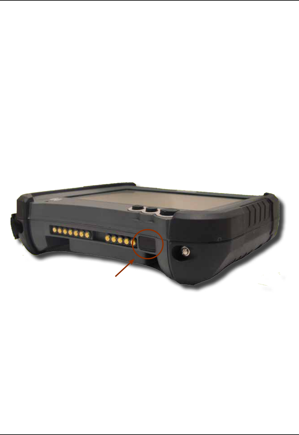
IRDA INTERFACE (SELECTED MODE)
An IrDA ‘Infrared Data Association” makes communication & data exchange possible over
infrared light IrDA interfaces are used in palmtop computers, mobile phones, and laptop
computers etc, (although today, many laptops no longer offer IrDA in favor of Bluetooth)
Often, this interface is used primarily for communication between PCs, to communicate to server or for
printing Refer to your Application Specialist or immediate supervisor for more details regarding the use of this
interface from your CE8000B unit Some basic information follows:
• To communicate using an IrDA interface, the peripheral or remote computer must also be equipped with
an IrDA Interface or communication will be possible
• If both devices are equipped with an IrDA Interface, point the red window located on the side of the unit next to the
connector pins, towards the IrDA receptor on the peripheral (Not different to using an ordinary TV remote control)
• Communication will be possible at a distance not farther than one (1) meter, (3 feet)
CMU055-A2a
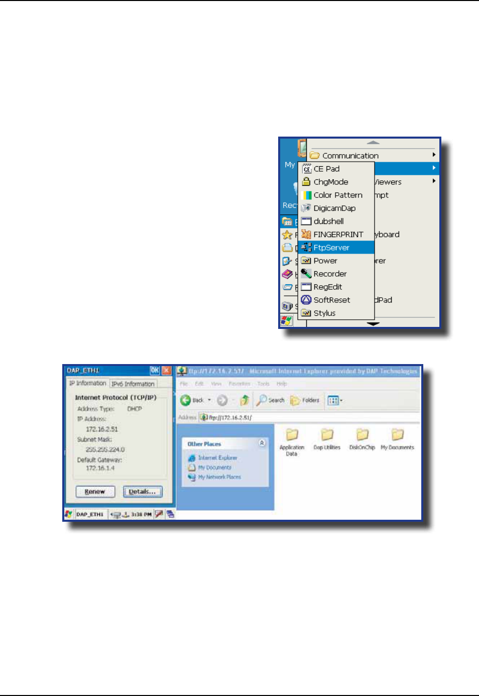
TRANSFERRING FILES IN FTP MODE
The CE8000B unit includes an FTP Server access which makes transferring les easy and does not require
the use of ActivSync
1 Insert the CE8000B unit into the Ofce Cradle
Once unit is inserted this will automatically activate the FTP server If the
FTP server does not activate automatically, follow the steps below
2 Click on:
a) Start
b) Program
c) DAP Utilities
d) FTP Server
3 Open Internet Explorer on your Desktop
Computer then type:
4 The contents of your CE8000B unit will appear Simply use the conventional
functions to manage its contents
CMU055-A2a
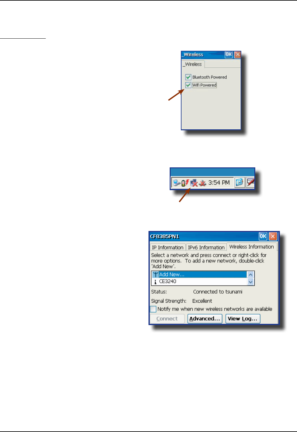
WIRELESS & BLUETOOTH OPTIONS (BWE VERSIONS)
Using Wireless
To set wireless options, click on:
1 Start
2 Settings
3 Control Panel
4 _Wireless
5 Check to activate or un-check the options to
deactivate these features
6 Double-click on the network applet in the Task Bar
7 Select Wireless information tab
8 Choose the desired network connection
CMU055-A2a
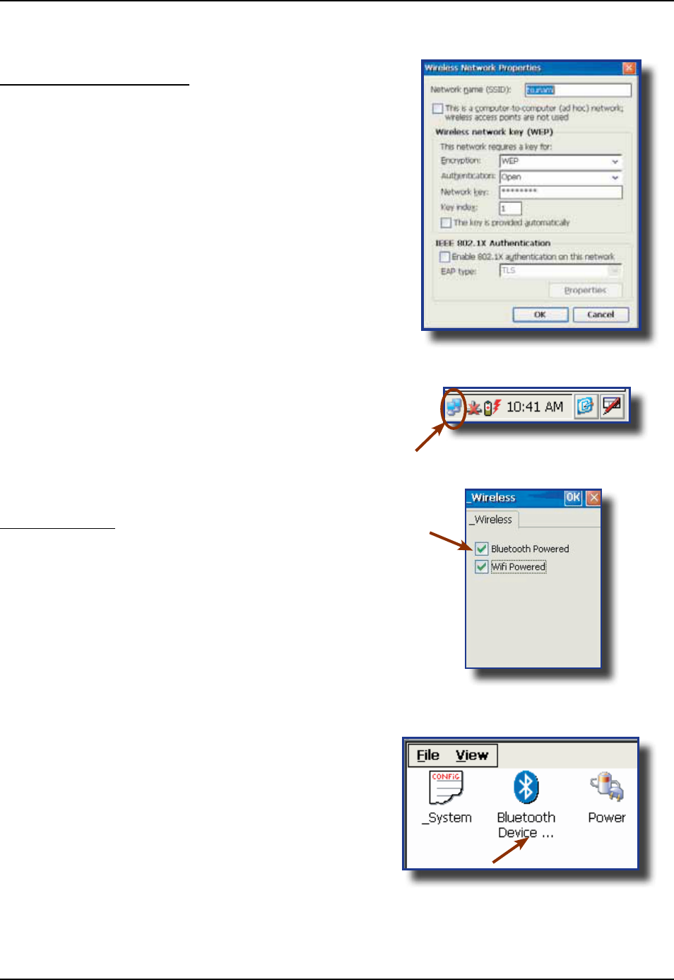
9 To congure the network connection,
double click on the desired access point
10 Once network connection is established
successfully, the network applet will display as
active
Using BlueTooth
To set wireless options, click on:
1 Start
2 Settings
3 Control Panel
4 _Wireless
5 Check to activate or un-check the options to
deactivate these features
6 Return to Control Panel
7 Select Bluetooth Device
Using Wireless (Continued)
WIRELESS & BLUETOOTH OPTIONS (CONTINUED)
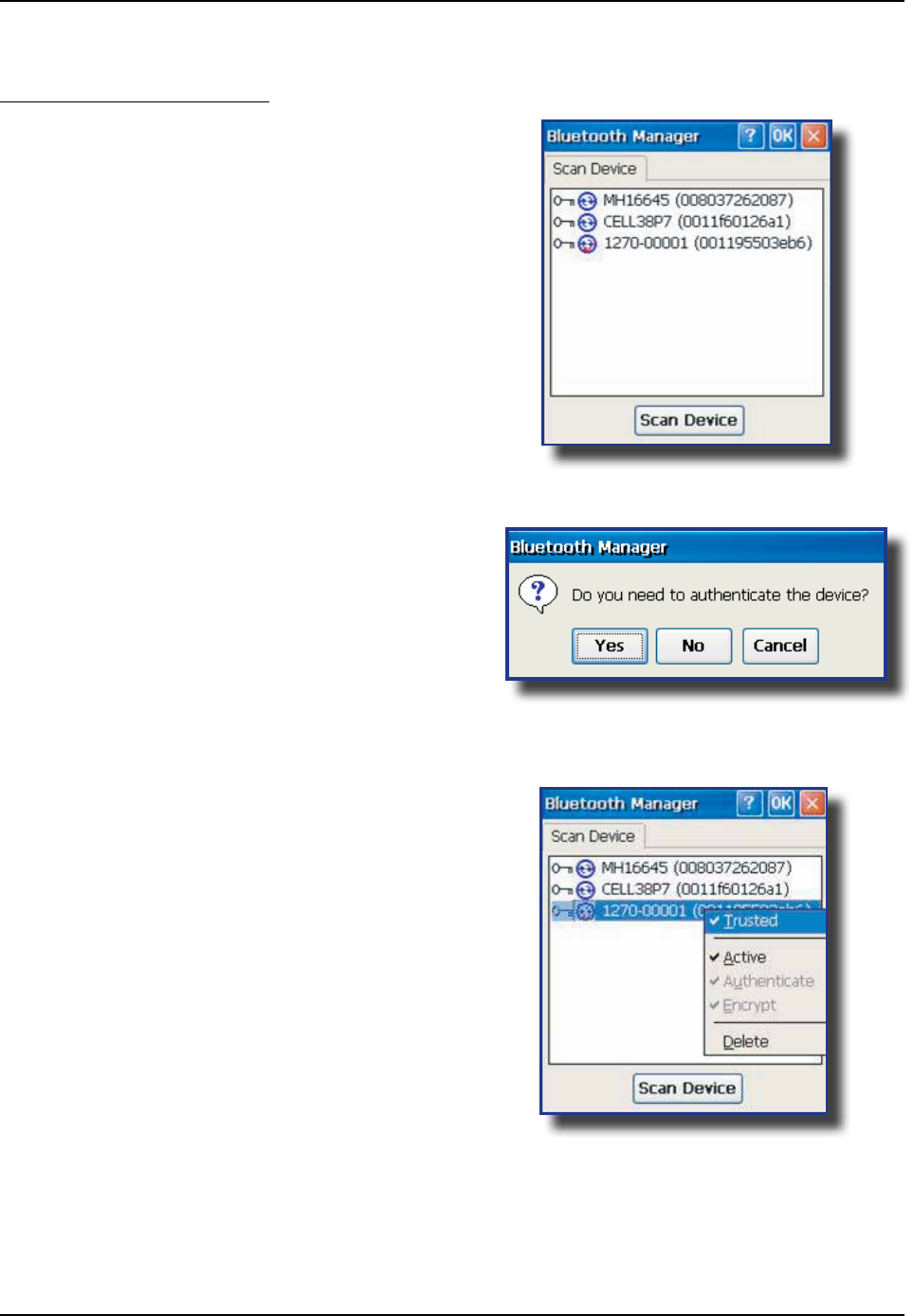
CMU055-A2a
8 Use this applet to locate peripheral or delete
Bluetooth partnership
9 Click on Scan to locate peripheral
10 Authentication might be required, refer to your
supervisor for authentication and identication
codes
11 Once authentication is completed, the device
will be active
WIRELESS & BLUETOOTH OPTIONS (CONTINUED)
Using BlueTooth (Continued)
CMU055-A2a
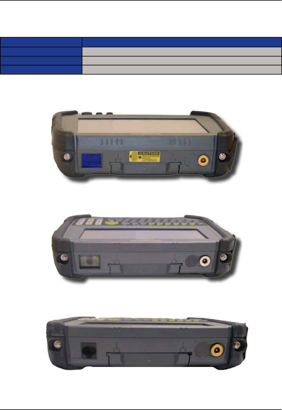
Only one option can be installed on unit at one time
Laser Scanner
1D/2D Barcode Scanner
RJ45 - Ethernet Connection
CMU055-A2a
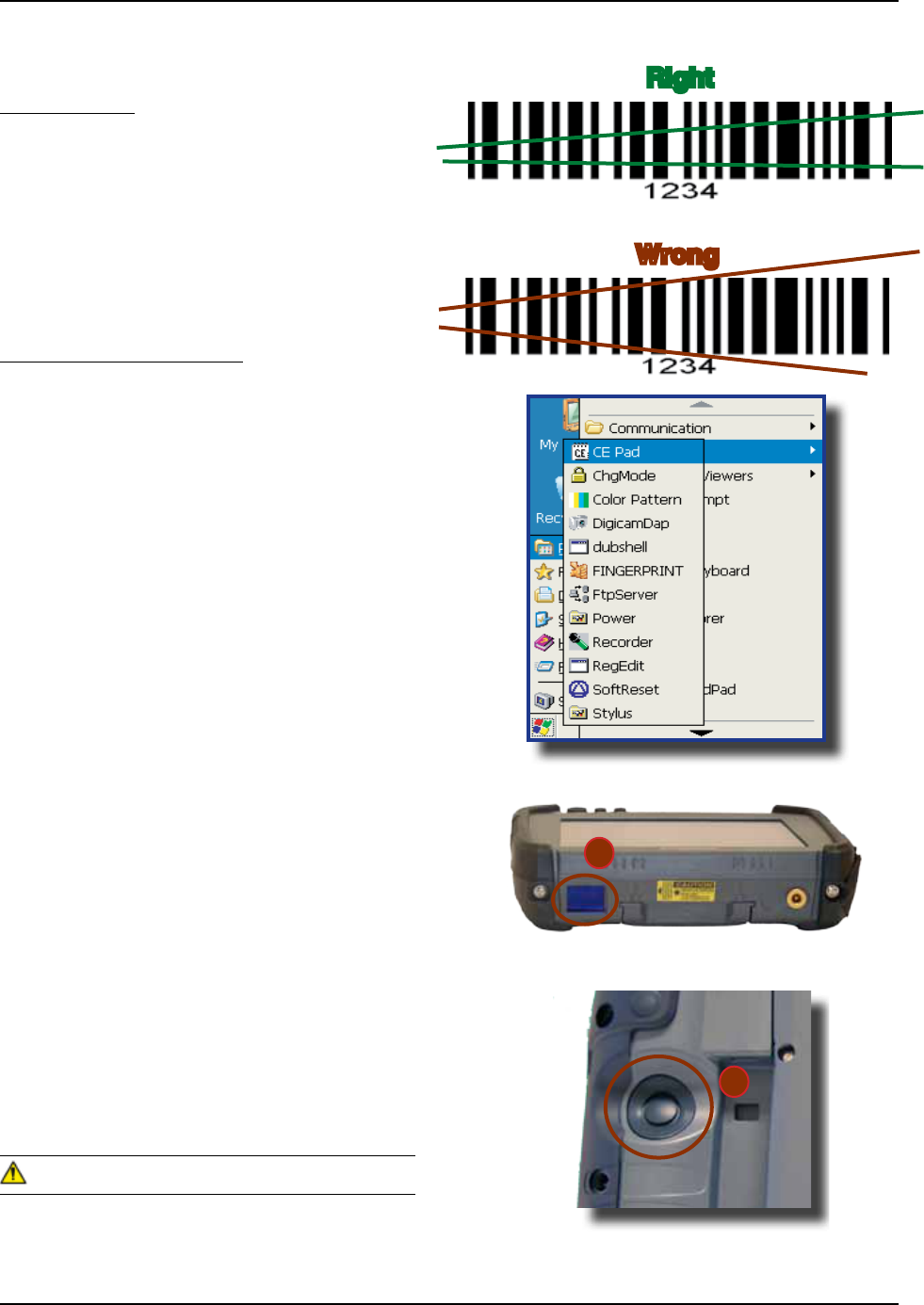
BARCODE READERS
Laser Scanner
The ‘Laser Scanner’ function will depend on the
application used and a special software driver
Refer to your application’s User Guide for further
instructions Information included are basic
scanning instructions
Refer to the diagram to the right for right and wrong
scanning methods
Testing the Laser Scanner
1 To test the Laser Scanner, click on:
a) Start
b) Program
c) DAP Utilities
d) CE Pad
2 To activate scanner, point the top of the
unit toward the barcode label needed to be
scanned
3 Press the ‘SCAN’ Key and move
the unit back and forth so the
beam completely crosses the label
4 Once the label has been decoded, the unit will
sound a short ‘beep’
If you keep the Scan key pressed for too
long, the unit will stop scanning by itself after a
few moments The unit will sound two (2) beeps to
indicate that no barcode has been detected
Refer to the CE8000B Technical
Guide for further instructions on programming
• Avoid Exposure to Laser Light Beam
• Do not intentionally look into the Laser Light
Beam
a
b
CMU055-A2a
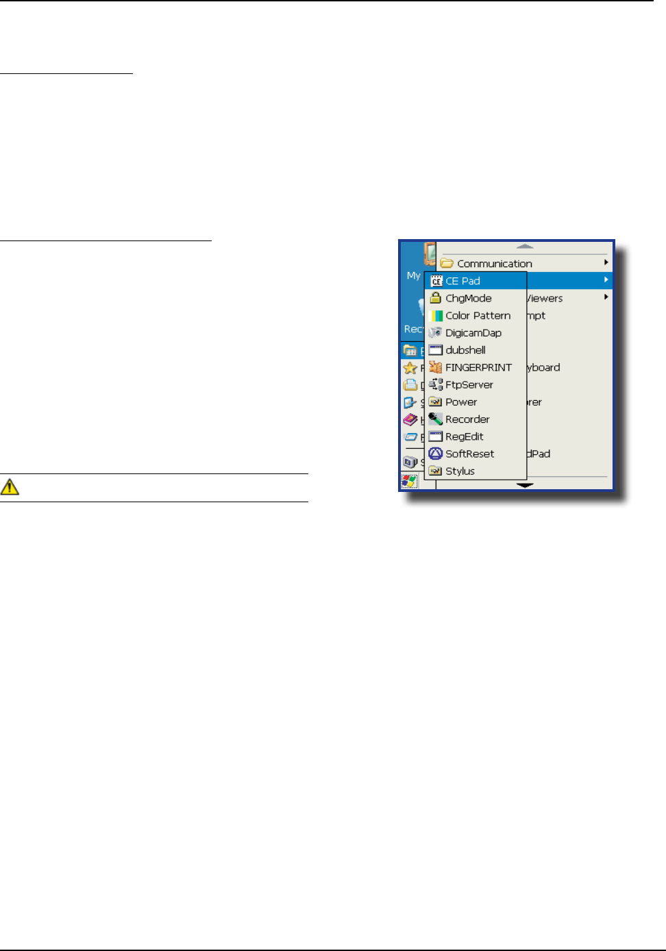
Testing the 2D Barcode Reader
1 To test the reader, click on:
a) Start
b) Program
c) DAP Utilities
d) CE Pad
2 Hold the unit steadily at a distance of 10 cm (4
in), from the barcode
3 To activate reader, press the F3 Key
Do not move the unit while reading or unit will not
be able to read barcode
2D Barcode Reader
This special option is usually installed and congured in-house at the manufacturer’s
The 2D Barcode Reader is primarily controlled by the client application and a special driver Therefore, please
refer to your application specialist or supervisor for further instructions
You may also refer to the CE8000B Technical Guide located on DOCUDAP for further instructions on
programming
Unlike the laser scanner, the 2D reader does not “swipe” the barcode, but rather, it takes a reading
much like a “photograph” which is then recognized and interpreted by the unit Reading a barcode can be
taken from any angle
The 2D Barcode Reader will emit a red beam allowing the user to adequately focus on the barcode needing
to be read
Once the reading has been completed, the device will emit a sound The numeric code will then be displayed
on the screen
You can release the trigger at any time to cancel the reading
BARCODE READERS (CONTINUED)
CMU055-A2a
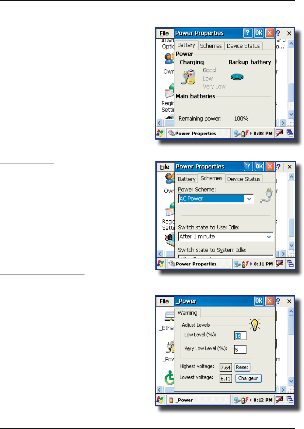
ADVANCED BATTERY OPTIONS
To See Power Remaining
1 Under Windows CE 50, click on:
a) Start
b) Settings
c) Control Panel
d) Power
e) Battery
Preserving Power
It is possible to extend battery life by modifying the
power delays of the unit, screen and backlighting
settings
To congure power settings:
1 Click on the “Schemes” Tab
Move Scroll bar up or down, or click the
up or down arrows to see the entire menu
Battery Power Management
All CE8000B units are delivered with a calibrated
Main Battery
1 To setup the screen and backlight delays,
click on:
a) Start
b) Settings
c) Control Panel
d) _Power
e) Power Off
2 Dene “Low Level” & “Very Low Level” as per
your selection and applications used
The default settings are 16% for “Low
Level” and 5% for “Very Low”

CMU055-A2a
ACTIVESYNC COMMUNICATION
Using the Microsoft ActiveSync communication, it is possible to transfer les between a desktop computer
and the CE8000B unit Communication is possible through the serial port or USB client
With Microsoft Outlook 2002 or later, it is also possible to synchronize information between the desktop
computer and the CE8000B unit
ActiveSync Setup
ActiveSync Client is already installed on the unit and the “ActiveSync Host” must be setup on the
desktop computer in order to function If the host is not installed on the desktop, follow the instructions
below
1 Download the latest version of the Microsoft ActiveSync Software from one of the following sites:
a) From the
b) From @
It is strongly recommended to use ActiveSync 38 or higher
2 Once download is complete, launch the ActiveSync program A screen will appear prompting
you to Setup Microsoft ActiveSync Program
3 Click
4 A screen will appear prompting you for what folder to save the program The is
recommended
5 Click
6 Once installation is completed, click If prompted “Create Partnership between Desktop and
CE Device”, Click
7 Once the installation has been successfully completed, the ActiveSync Applet will be displayed on your
desktop and an icon will be added to your Task Bar (The Software program will also be available through
the Start Menu)
connect your CE8000B unit until the installation has completed
CMU055-A2a
PARTNERSHIP WITH ETHERNET CRADLE
The “Ethernet Partnership” is only possible with ActiveSync 37, 38 or lower
The Ethernet connection requires the use of a cradle model # CBCE840-3 or CBCE840-4 and an Ethernet
cable connected between the cradle and your network Refer to the section for further
instructions
An initial Ethernet connection normally requires a “Partnership” with your “Host” computer using a serial or
USB port DAP Technologies has made these following programs available to assist in the creation of the “
Ethernet Partnership” when using the Ethernet cradle:
• SetPartnerShipexe (Already installed on the CE8000B unit)
• PartnerShip Serverexe (This program must be downloaded)
1 Go to http://wwwsupportdaptechcom
2 Refer to CENET PUBLIC DOWNLOAD
3 Copy to a folder that will be easily accessible; eg Desktop Folder
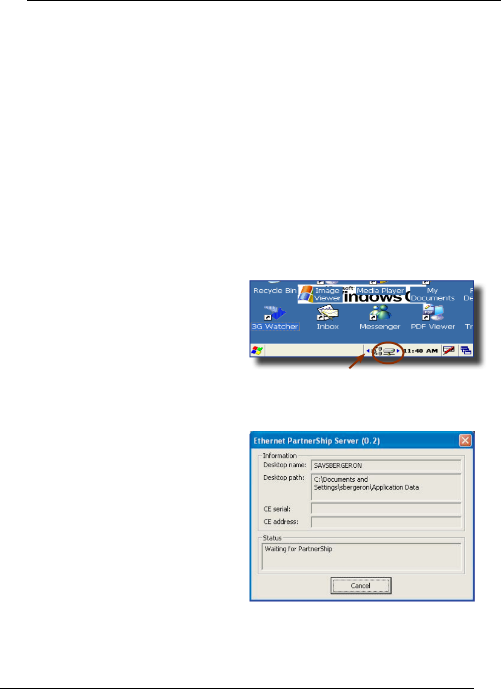
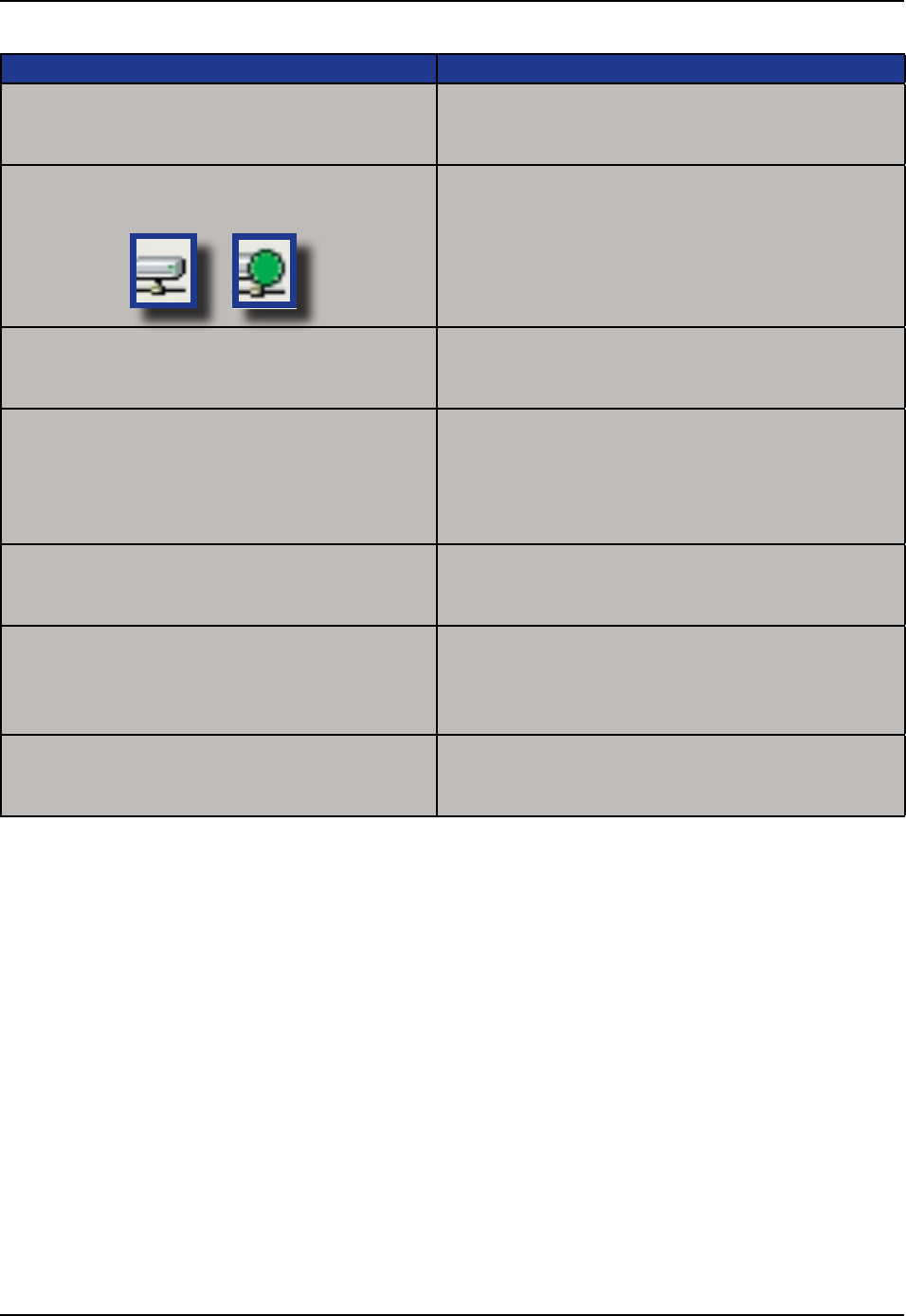
1 Install the CE8000B unit into its Ethernet Cradle
and wait until the network has been detected
2 Launch on the Host
computer
Click on arrow to see more icons
if network icons are not visible
Network connection
is established
CMU055-A2a
PARTNERSHIP WITH ETHERNET CRADLE (CONTINUED)
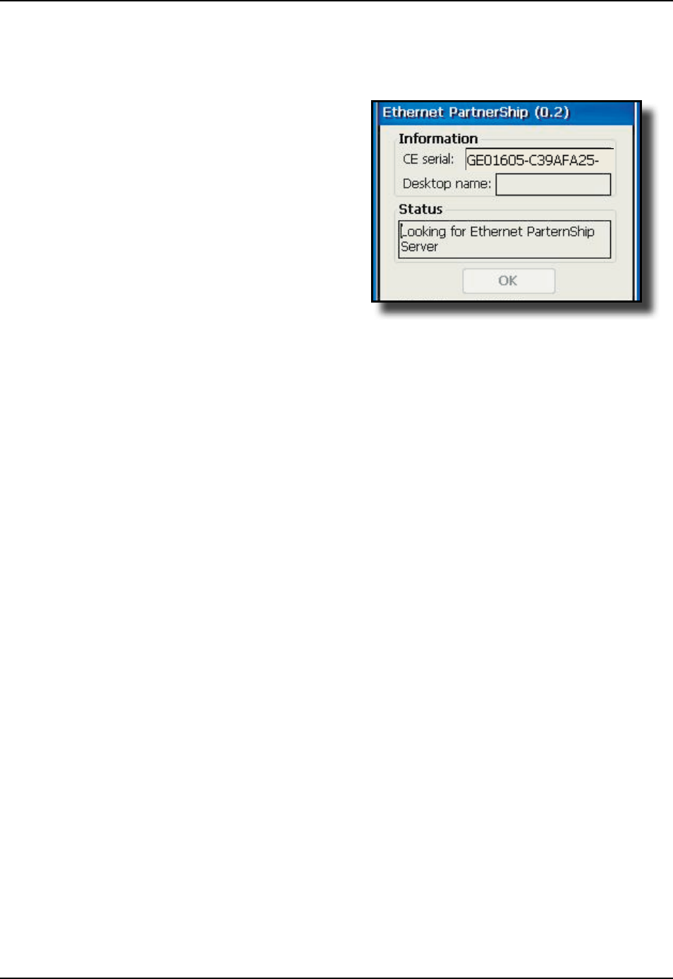
3 To establish PartnerShip, click on:
a) Start
b) Communication
c) Set PartnerShip
4 The Ethernet PartnerShip should be
established within a few seconds
This procedure needs only to be done
once to create the rst “PartnerShip”
5 To launch ActiveSync, Click on:
a) Start
b) Program
c) Communication
d) ActivSync
For subsequent connections, simply
follow step 5 to start ActiveSync
CMU055-A2a
ADVANCED USER INFORMATION
To obtain the most current technical information on
your CE8000B unit, you must rst register your unit
@
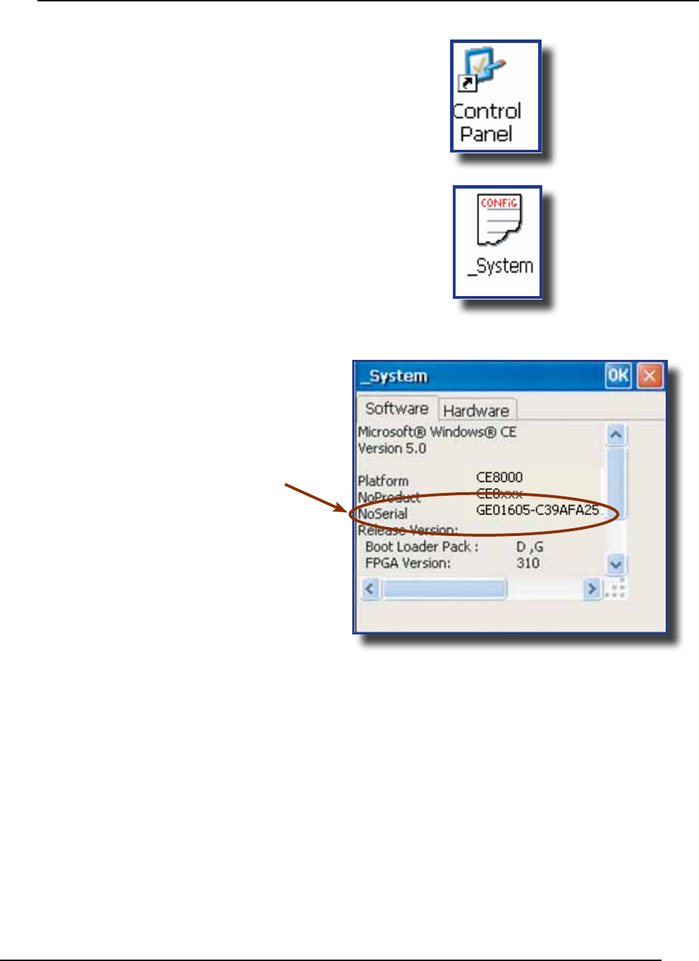
1 Click on Control Panel
2 Click on the _System Applet
3 From this _System Applet Window, note the
16 digit serial number
4 Start your Internet Browser
5 Go to:
CMU055-A2a
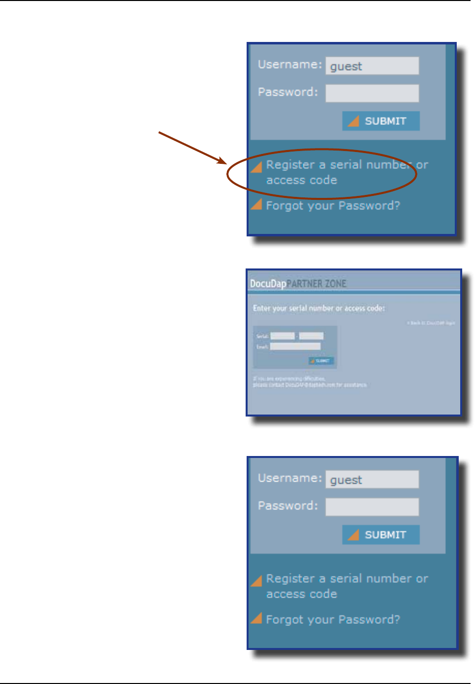
6 Click on
7 Enter your CE8000B unit’s serial number
noted earlier
8 Enter a valid Email address and your user
information and password will be forwarded
to you
9 Return to DocuDap Login and enter the
information that was provided to you and
click “
10 You may now surf the Technical
Web Site for more technical and
advanced user information
ADVANCED USER INFORMATION (CONTINUED)
CMU055-A2a
This section lists several programs that are included with the CE8000B unit and provides a brief description
of their functions However,
It is the intent of this User Guide to describe the applications included Please refer to DAP Technologies
Technical Web Site for further instructions on DAP Technologies programs included or the Microsoft Web Site
for Microsoft Programs included
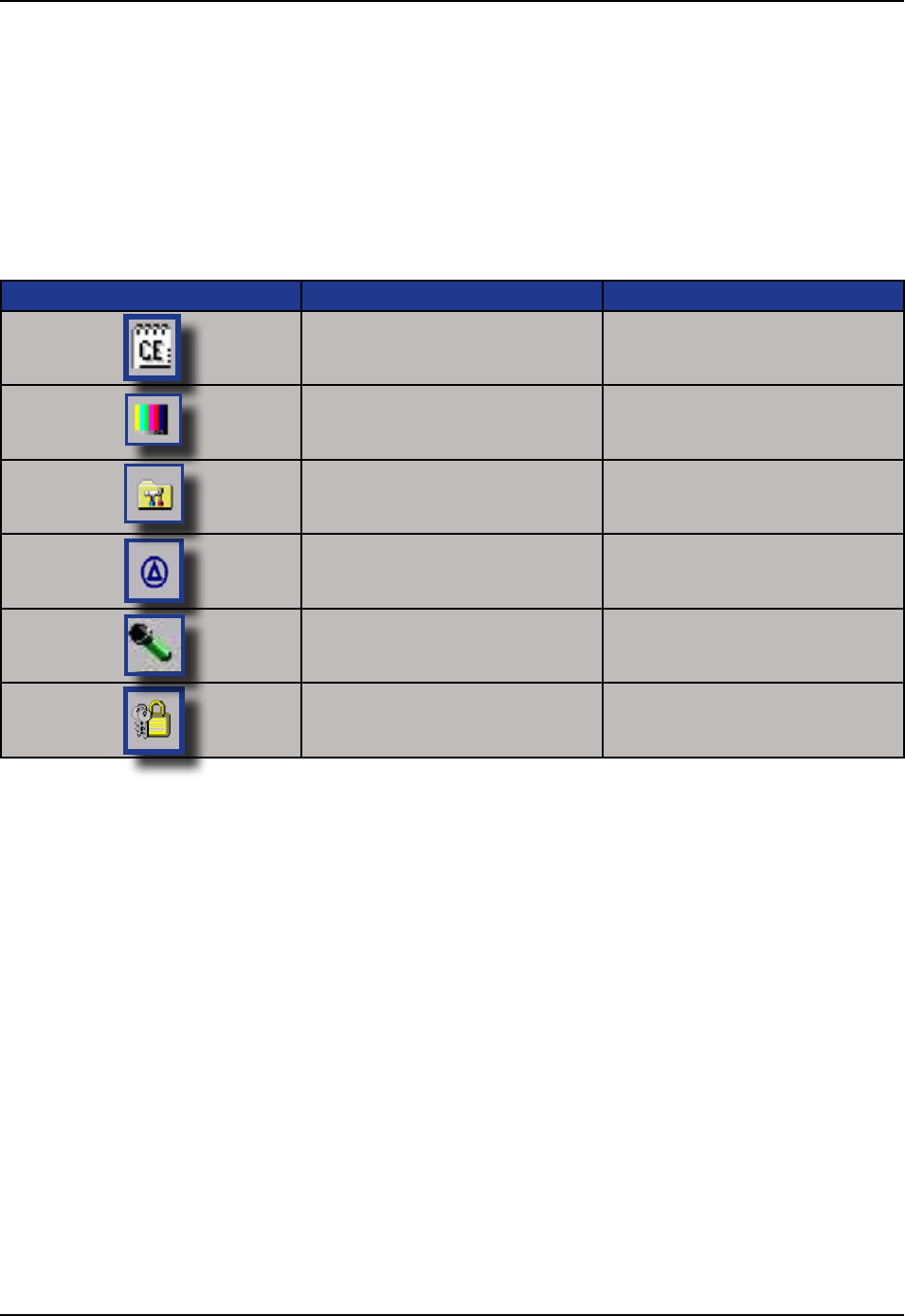
DAP CE8000B PROGRAMS
CE Pad A Small Test Editor
Color Pattern
To verify color screen quality
Power Remaining Display Power Applet
Soft Reset Reset the unit The supervisor
mode is required
Recorder Allows you to playback wave les
and recorded messages
Change Mode Switch between the User and
Change mode
CMU055-A2a
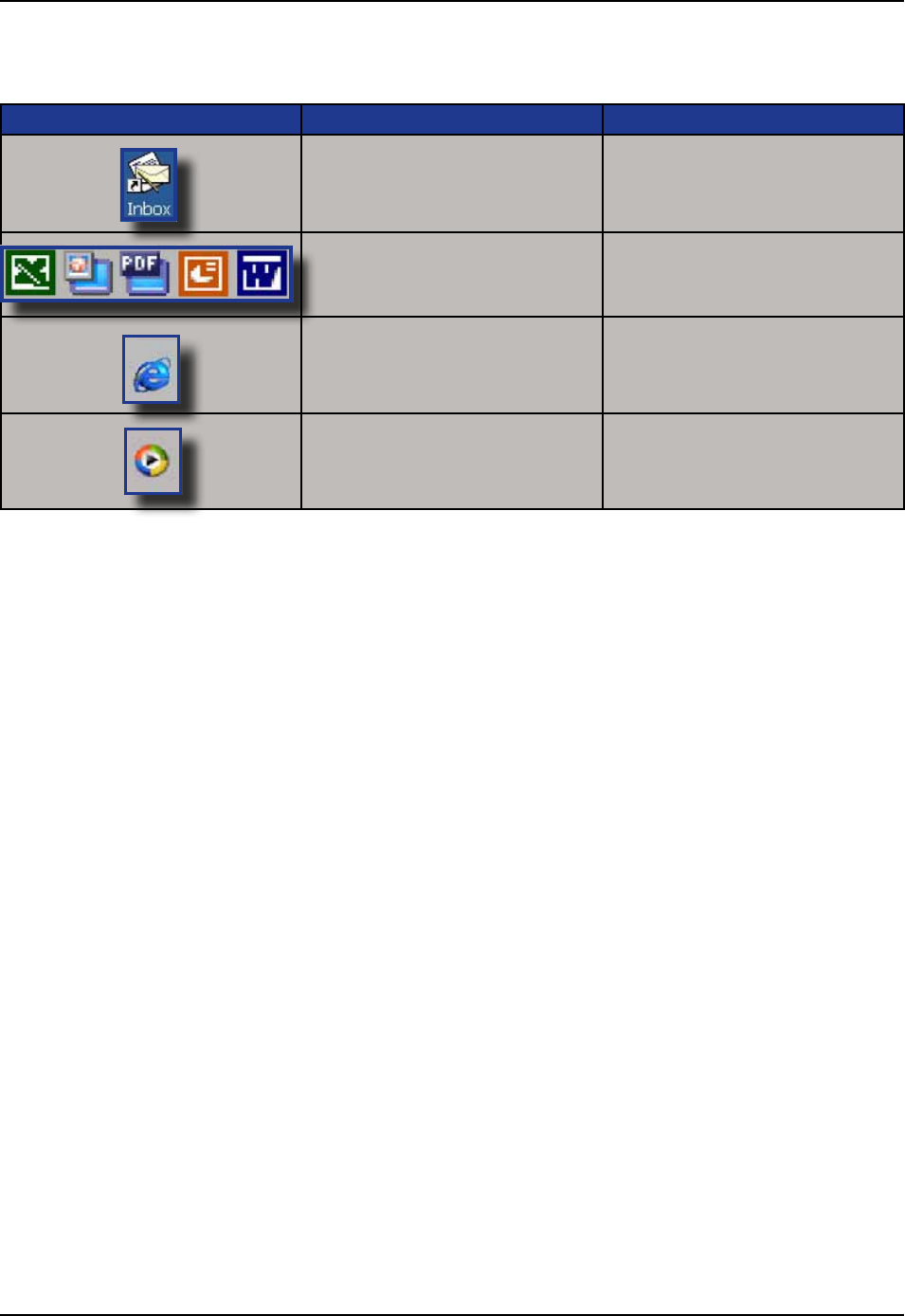
MICROSOFT PROGRAMS
Inbox Send and receive Emails by
synchronizing Desktop with
CE8000B unit
Microsoft Viewer Suite Will display Excel les, images,
PDF, PowerPoint and Word les
Internet Explorer Surf the Web by synchronizing
pages with desktop computer or
by connecting to Internet
Media Player Play music or video les
CMU055-A2a
1 Still some power remains but it is recommended
that you replace the battery before Data is lost
1 Verify Network cable is connected on the back of
the cradle
2 Verify Network cable is not defective
3 Ethernet on-board adapter may be deactivated or
in Power Save Mode
1 Verify that the unit is turned on
2 Verify that the battery is fully charged
1 Verify batteries --- batteries may need re-charging
Once unit is placed on the charger, the unit should
turn itself on in the next few seconds and re-start
the operating system
1 Verify that the PC Card is inserted properly Refer
back to “Using PC Cards” section for further
instructions
1 Verify the display contrast settings are appropriately
set Use the contrast keys to adjust the settings
(Refer to
for further instructions
1 Verify unit is properly connected to the charger
2 Verify “shutoff” feature is properly congured
CMU055-A2a
The CE8000B Unit is a reliable product requiring little maintenance Only occasional replacement of the
battery and the carrying strap is required
There are no user-serviceable parts inside the CE8000B Unit Do not try to repair the unit as this may affect
proper functioning as well as the warranty
STORAGE
• If the unit is not going to be used for a few days or more, it is recommended to keep the unit directly on
the charger
• If the unit is not going to be used for a few weeks, it is strongly recommended that the unit be fully charged
and stored in a location where the temperature will be between +20C (+68F) to +25C (+77F)
• If the unit has been stored for a long period of time, recharge the battery completely prior to use
• If extended storage time is necessary, it is important to backup all data to ensure no data is lost or
corrupted
• Keeping the unit on the Charger is also possible, however, this may affect the battery life and capacity
over time
CLEANING
Use a normal soft cloth and mild soap to clean the CE8000B unit Do not use abrasives as these cleansers
may damage the nish and scratch the touch screen Ensure that all compartments are properly closed prior
to cleaning unit
SHIPPING THE UNIT
The CE8000B units have been designed to withstand vibrations and shocks that can occur during normal
use of the product However, should shipping one of these units be required, it is strongly recommended
that these be packaged in the same packaging the unit was delivered in, or similar packaging to avoid any
damage to the units during transportation
CARRYING STRAP
To clean the strap, simply use a mild soap and a normal soft cloth If there is extensive wear on the strap, it
may be time to change it
CMU055-A2a
BATTERY MAINTENANCE
Main Battery
The high-quality Lithium-Ion battery provided with your unit may be re-charged over 500 times according to
the battery manufacturer
If the battery’s duration does not last the normal time-frame specied, it may be time to change it The
main battery should last from 12 to 24 months if used under normal working conditions
Backup Battery
The Backup Battery will normally not need to be replaced during the expected life of the CE8000B unit
Re-charge as specied after use
Replacing the Battery
Always turn the unit off before removing the battery The CE8000B unit uses an approved battery to
ensure a quicker charging time, longer battery life and resistance to shock and vibrations To ensure that
the batteries are appropriate for use on DAP Technologies equipment, it is strongly recommended that
these be purchased directly through DAP Technologies or one of its distributors (Check for the DAP or
DAP Technologies logo on the battery)
1 Turn off the CE8000B Unit (Refer to “Turning
the Unit Off Manually” Section for further
instructions)
2 Turn Battery Compartment Screw counter-
clockwise to unlock
3 Remove the battery
4 Replace the battery ensuring to insert top end
of the battery rst and towards top of the unit
• Personal injuries may result if batteries are not
handled with care
• If battery becomes unusable, dispose of it
immediately
• Keep the battery away from heat sources,
including open res and direct sunlight
• Never disassemble the battery
• Do not place the battery on metal objects as
this could short circuit the power contact pins
The type of main battery used in the CE8000
series is not considered hazardous waste Refer to
your local regulations on how to dispose of battery
appropriately
TOUCH SCREEN MAINTENANCE
The Touch Screen requires minimal maintenance Only appropriate care when using and cleaning the Touch
Screen is required Use the Stylus provided with the unit when using the Touch Screen to ensure other
pointed devices do not damage the screen When cleaning, ensure to use a mild detergent and soft cloth
• Do Not use abrasives as these may damage the nish and scratch the Touch Screen
• Replace or clean the Stylus as soon as it seems damaged or dirty
UNIT WITH LASER OPTION
The efciency of the Laser reading will depend on the quality of the plastic window Any scratch, dirt or
nger prints will degrade the reading quality
1 Clean using a mild detergent and soft cloth to ensure no scratches to the window (A plastic lens cleaner
can also be used for cleaning the window)
QUICK-REFERENCE REPLACEMENT PARTS LIST
Lithium-Ion Battery DCCE800-2
Carrying Strap (4 per package) DCCE801
Stylus (Pen), 5 units per package DCCE500
Anti-Glare Screen Protector DCCE816
Second Skin for Keyboard SS8640
CMU055-A1
CMU055-A2a
The Waste Electrical and Electronic Equipment Directive (WEEE) is a European directive established in 2003
for the collection, recycling and recovery targets for all types of electrical goods
This European Directive imposes the responsibility for the disposal of waste electrical and electronic equipment
on the manufacturers of such equipment
In accordance to this directive, DAP Technologies will assist you in the proper disposal of your DAP Units
For further instructions on how to dispose of these units, please refer to our web site:
CMU055-A2a
The CE8640B, CE8810B & CE8820B have been tested and are in compliance with the 89/336/EEC European
Directive for Electromagnetic Compatibility
EN 55022 Radiated & Conducted, Class B
ENV 50204 Radiated Electromagnetic eld from Radio Telephones
EN61000-4-6 Radio Frequency Continuous Conducted
EN61000-4-3 Radiated Immunity
CEI / IEC 60825-1 Laser Safety Approvals
21 CFR Chapter I,
Subpart J, Part 104010
Performance Standards for Light Emitting Products
(Class II Laser Product)

CMU055-A2a
FCC STATEMENT
This equipment has been tested and found to comply with the limits for a Class B digital device and is in
compliance with the FCC guidelines from Part 15 These limits are designed to provide reasonable protection
against harmful interference when the equipment is operated in a residential environment This equipment
generates, uses, and can radiate radio frequency energy and, if not installed and used in accordance with the
instruction manual may cause harmful interference to radio communications However, there is no guarantee
that interference will not occur
COPYRIGHT POLICY
Any software described in this document is provided under a license agreement or non-disclosure agreement
It is strictly prohibited by law to copy any portion of the software provided by DAP Technologies onto any
media format
DAP is a registered trademark of Roper Mobile Microsoft, MS-DOS and Windows CE are registered
trademarks of Microsoft Corporation PCM CIA and PC Cards are also registered trademarks of Microsoft
Corporation
A Copyright Policy is also applicable for any software provided by Microsoft on DAP Technologies
Products Please refer to for further information

CMU055-A2a
You have acquired a DAP Technologies device that includes software licensed from Microsoft Corporation
The Microsoft software included in your device, as well as associated media, printed materials, and online
documentation are all protected by Copyright Laws and International Copyright Treaties If you do not agree
with this End-User License Agreement (“EULA”), use of this device, or use and copying of, any installed
software is strictly prohibited We strongly recommend that you immediately contact a DAP Technologies
Customer Representative for return instructions of the unused unit
LICENSE GRANT
• The software must only be used with the device provided
• There are no warranties for the software included
• Reverse engineering is strictly prohibited
• Software transfer is allowed but with restrictions You may permanently transfer rights under this EULA
only as part of a permanent sale or transfer of the device as long as the recipient agrees to this EULA If
the software is an upgrade, any transfer must also include all prior versions of the software
JAVA SUPPORT
The software may contain support for programs written in Java Java technology is not designed, manufactured,
or intended for use or resale as online control equipment in hazardous environments requiring fail-safe
performance These environments include nuclear facilities, aircraft navigation, communication systems, air
trafc control, life support machines, or weapons

CMU055-A2a
As manufacturer, DAP TECHNOLOGIES will replace or repair, at its discretion, any products that prove to be
defective, in either material or workmanship, for a period of TWELVE (12) MONTHS following the purchase date of
the “EQUIPMENT” (handheld “MICROFLEX” unit and cradle) and for a period of NINETY (90) days following the
purchase date of “ACCESSORIES” (accessories and peripherals) sold by DAP TECHNOLOGIES The warranty
only covers the material and workmanship
This warranty does not cover damages caused by misuse, abuse, neglect, or damages occurred during shipping or
storage; the warranty does not cover any modication or servicing by anyone other than a DAP TECHNOLOGIES
Authorized Service Center
DAP TECHNOLOGIES cannot be held responsible for any damage caused by the misuse of the equipment or by
any other software or hardware added The device and its accessories should not be used in applications where
device failure could result in physical harm or loss of life
The operating system Windows CE and all other software sold or supplied by DAP TECHNOLOGIES are provided
as is, without any warranty, either expressed or implied
In no event shall DAP Technologies be held liable for any direct damages, indirect damages or damages incurred
by the loss of present or prospective prots arising from the failure in performance of the equipment No claim
may be made against DAP TECHNOLOGIES whether arising from contractual, extra-contractual or statutory
liability
This warranty hereby excludes all other legal warranty related to the quality of the product or its capacities to
fulll specic purposes, including all warranties granted by the United Nations Convention on Contracts for the
International Sales of Goods, the application of such Convention being expressly excluded
Revised May 2008 WS08-05A1
In order to have your product serviced, you must rst obtain a Return Material Authorization (RMA) from DAP
TECHNOLOGIES You may then return your equipment, correctly enclosed in its original packaging if possible,
to your Value Added Reseller (VAR), an Authorized Service Center, or directly to DAP TECHNOLOGIES
Service under the conditions of this warranty requires prepaid shipment from your facility to a Service
Center
The equipment and its accessories have no user serviceable parts
To obtain a RMA you can make your request by phone or use our on-line form at:
The original purchaser may, at any time during the initial warranty period, extend the warranty through
purchase of a DAP CARE Service Contract For more information, contact DAP TECHNOLOGIES

875 Charest Boulevard West, Suite 200
Quebec City, Quebec
Canada G1N 2C9
T: (418) 681-9394
F: (418) 681-0799
TF: (800) 363-1993
E: SalesNA@daptechcom
7450 South Priest Drive
Tempe, Arizona
United States, 85283
TF: (800) 363-1993
E: SalesNA@daptechcom
25 Nufeld Way
Abingdon, OX14 1RL
England
T : + 44 (0) 1235 462130
F: + 44 (0) 1235 462131
TF: + 44 (0) (800) 8899 1000
E: SalesUK@daptechcom
+ 1 (418) 681-7833
+ 1 (800) 363-1993
TechSupportCanada@daptechcom
+ 1 (518) 293-7824
+ 1 (800) 363-1993
TechSupportUSA@daptechcom
+ (800) 8899 1000
TechSupportEMEA@daptechcom

875 Charest Boulevard West
Suite 200
Quebec City, Quebec
Canada G1N 2C9
T: (418) 681-9394
TF: (800) 363-1993
F: (418) 681-0799
E: SalesNA@daptechcom
7450, South Priest Drive
Tempe, Arizona
United States, 85283
TF: (800) 363-1993
E: SalesNA@daptechcom
2010/03 CMU055-A2a wwwdaptechcom
Printed in Canada
25 Nufeld Way
Abingdon OX14 1RL
England
T: + 44 (0) 1235 462130
TF: + 44 (0) 800 8899 1000
F: + 44 (0) 1235 462131
E: SalesUK@daptechcom