Transact Campus DR4100X007 Contactless Card Readers User Manual 1353 AC3100 Installation
Blackboard Inc. Contactless Card Readers 1353 AC3100 Installation
Contents
- 1. DR4100 Brochure
- 2. DR4110 Brochure
- 3. DR4200 Brochure
- 4. DR4210 Brochure
- 5. Installation Manual
Installation Manual
AC3100
Installation Guide
PRINTED APRIL 14, 2011
"Underwriters Laboratories Inc. (“UL”) has not tested the performance or reliability of the security or
signaling aspects of this product. UL has only tested for fire, shock and/or casualty hazards as outlined in
the U.S. and Canadian (Bi-National) Standard for Safety of Information Technology Equipment, CSA C22.2
No. 60950-1-03; UL 60950-1 First Edition dated April 1, 2003. UL Certification does not cover the
performance or reliability of the security or signaling aspects of this product. UL MAKES NO
REPRESENTATIONS, WARRANTIES OR CERTIFICATIONS WHATSOEVER REGARDING THE
PERFORMANCE OR RELIABILITY OF ANY SECURITY OR SIGNALING RELATED FUNCTIONS OF
THIS PRODUCT."
This device complies with Part 15 of the FCC Rules. Operation is subject to the following two
conditions: (1) This device may not cause harmful interference, and (2) this device must accept any
interference received, including interference that may cause undesired operation. Part 15.21:
Changes or modifications not expressly approved by the party responsible for compliance could void the
user’s authority to operate the equipment.
NOTE: The manufacturer is not responsible for any radio or TV interference caused by
unauthorized modifications to this equipment. Such modifications could void the user’s
authority to operate the equipment. This equipment complies with the FCC radiation exposure
limits set forth for an uncontrolled environment. End users must follow the specific operating
instructions for satisfying RF exposure compliance. The antenna(s) used for this transmitter
must be installed to provide a separation distance of at least 20 cm from all persons and must
not be co-located or operating in conjunction with any other antenna or transmitter.
Blackboard Inc. AC3100
Tested To Comply
With FCC Standards
FOR HOME OR OFFICE USE
This Class A digital apparatus complies with
Canadian ICES-003

Contents
PRINTED APRIL 14, 2011 I
AC3100 INSTALLATION GUIDE
4 AC3100 Installation
4 Mount the AC3100
6 Connect the AC3100 to the power source
7 Connect the AC3100 to the network
8 AC3100 Communication Configuration
10 Configure Communication using Front Panel & Service Card
11 Configure Communication using RS-232 or Telnet
13 AC3100 Transaction Process
13 Deposit Funds to an Existing Account
13 Purchase a Visitor Card
13 Check Account Balance
14 AC3100 Manager Card Functions
14 Display/print transaction totals
14 Terminal setup
14 Display device status information
14 Perform diagnostic functions
15 AC3100 Maintenance
15 Fill the Card Dispenser
15 Empty the Bill Box
17 Install the Paper Roll
20 Component Replacement
20 Replace the Power Supply Fuses
23 AC3100 Features & Specifications
23 AC3100 Features:
23 AC3100 Specifications:
24 BbTS Universal Edition Changes

Figures
PRINTED APRIL 14, 2011 II
Figure 1-1 What You Get .............................................................................................1
Figure 1-2 AC3100 Reader Details..............................................................................3
Figure 1-3 Mounting Illustration ...................................................................................5
Figure 1-4 RS-485 Reader Pinout ...............................................................................7
Figure 1-5 Configuration Flowchart .............................................................................9
Figure 1-6 Out-Of-Service Codes ..............................................................................10
Figure 1-7 Configuration Command Reference.........................................................12
Figure 1-8 Bill Box Removal ......................................................................................16
Figure 1-9 AC3100 Paper roll ....................................................................................18
Figure 1-10 Paper Roll Cut-off.....................................................................................18
Figure 1-11 Paper Entry Opening................................................................................19
Figure 1-12 AC3100 Fuse Locations...........................................................................20
Figure 1-13 AC3100 Components ...............................................................................21
Figure 1-14 Lock Lubrication .......................................................................................22
AC3100 INSTALLATION GUIDE
DOCUMENT 1353 REV 01
PRINTED APRIL 14, 2011 1
AC3100 INSTALLATION GUIDE
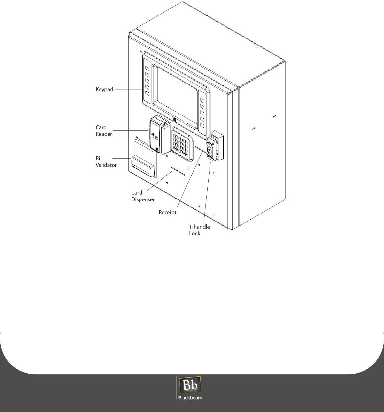
The Blackboard AC3100 enables cardholders to deposit to accounts, check balances, and purchase visitor
cards. The user interface utilizes an LCD display, keypad, and a combination mag-stripe and contactless
reader. Both the UNIX Edition and Universal Edition versions of the reader support user configurable
background color, text color, and banner images. Communication of host downloads, and reader
transactions use a maintained Transport Layer Security (TLS) Secure Communication Channel to meet
PCI Compliance.
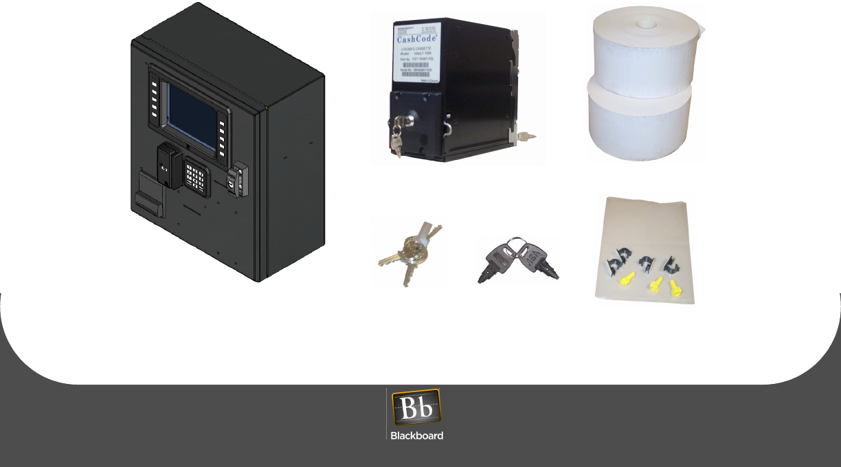
WHAT YOU GET
The following items are included with each AC3100:
• (2) bill boxes (one installed)
• (2) paper rolls
• (4) door lock keys
• (4) bill box key sets
• (1) hardware kit
Figure 1-1 What You Get
AC3100 Reader Bill Box keys
Spare Bill Box Paper rolls
Door lock keys
Hardware kit

PRINTED APRIL 14, 2011 2
The AC3100 connects to the Universal Edition Host via 10/100 Base-T or RS-485 through an IP Converter
(IPC). In UNIX Edition, the AC3100 optionally connects via RS-485. This unit replaces the Value Transfer
Station (VTS) on the UNIX Edition Host, and the Card Management Center (CMC) on the Universal Edition
Host.
The AC3100 accepts unattended deposits into existing cardholder accounts, and must be online to be
operational.
The following topics are covered in this document:
•AC3100 Installation (page 1-4)
•AC3100 Communication Configuration (page 1-8)
•AC3100 Transaction Process (page 1-13)
•AC3100 Maintenance (page 1-15)
•Component Replacement (page 1-20)
•AC3100 Features & Specifications (page 1-23)
AC3100 INSTALLATION GUIDE
DOCUMENT 1353 REV 01
PRINTED APRIL 14, 2011 3
Figure 1-2 AC3100 Reader Details

AC3100 INSTALLATION
PRINTED APRIL 14, 2011 4
AC3100 INSTALLATION
Mount the AC3100
The AC3100 can be surface mounted on a wall, recessed into a wall, or mounted on a pedestal. At least
four 3/8” diameter metal fasteners should be used to mount the enclosure. The installer is responsible for
ensuring the unit is securely installed to prevent theft.
WARNING: Use caution when opening the door without the enclosure secured to a wall or
pedestal. The weight of the door when open can cause the unit to tip over and cause injury.
Ensure the unit is securely mounted prior to operation.
To mount the AC3100
1Decide where to mount the unit, and how to route power.
Conduit knockouts are located in the junction box located in the lower left of the enclosure. Power
wiring must enter the unit within the junction box.
2Decide how to route the network wiring entering the unit.
NOTE: To eliminate risk of electrical shock or injury, do not route the network cable through
the junction box.
3Punch or drill mounting holes in either the back or the bottom of the unit, based on the application.
4Punch or drill a hole in the back or bottom of the cabinet to route the network cable.
This hole must be large enough to accommodate the RJ45 connector.
5Securely mount the unit, see: Figure 1-3 Mounting Illustration (page 5).
AC3100 INSTALLATION GUIDE
DOCUMENT 1353 REV 01
PRINTED APRIL 14, 2011 5
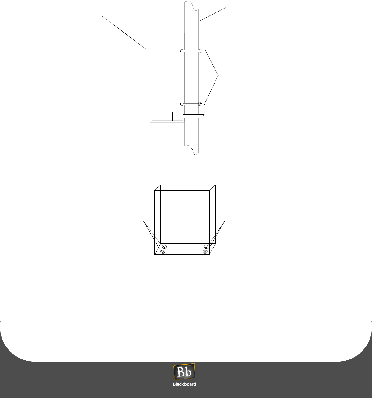
Figure 1-3 Mounting Illustration
AC3100
Wall
anchor
bolts
pedestal mount
3/8” bolt & washers3/8” bolt & washers
AC3100 INSTALLATION
PRINTED APRIL 14, 2011 6
Connect the AC3100 to the power source
Connect the unit to 120 VAC @ 60 Hz. Connect only to a 15A maximum branch circuit protection or
equivalent. Use a circuit breaker or switch to disconnect power when installing or removing the AC3100.
The AC3100 enclosure is provided with standard 1/2" conduit knockouts in the power junction box. The
power requirements are 120VAC @ 60Hz, 1.5 A max (line, neutral, and earth ground). The incoming wiring
must meet all applicable electrical codes.
NOTE: Before connecting wiring to the AC3100, ensure that all power has been disconnected
or that the circuit breaker is off.
To connect the AC3100 to the power source
1Turn OFF the Power Supply.
2Remove the junction box cover in the lower left corner of the enclosure by removing the 2 screws.
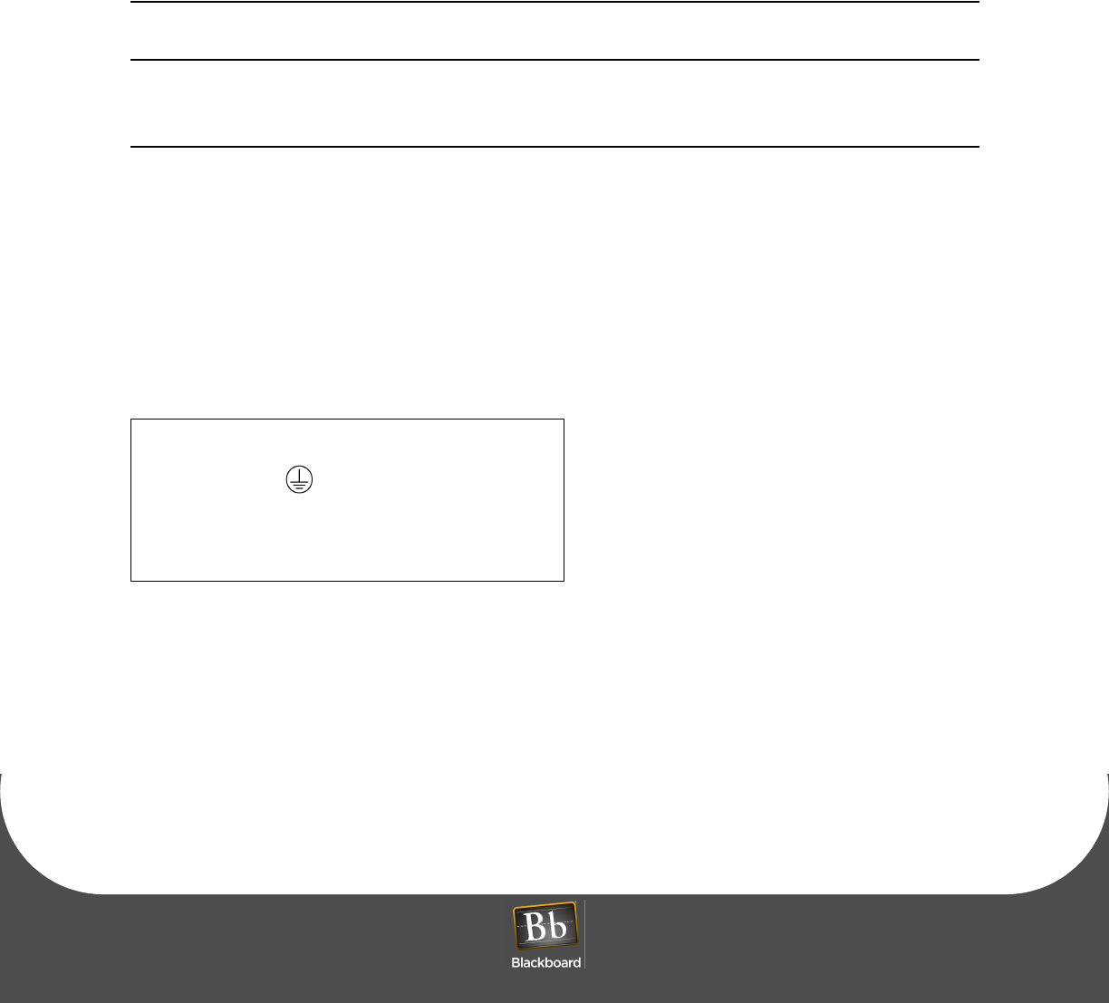
3Connect the 120VAC external wiring to the existing wiring in the junction box using the supplied wire
nuts.
Wires in the junction box are color coded and labeled as shown below.
4Re-install the cover, and secure with two screws.
5Turn ON the 120VAC power supply or circuit breaker to the reader, and then turn ON the AC3100.
The AC3100 powers-up and displays the power-up configuration.
Table 1-1: Junction box wiring
Wire Color Label Description
Green Earth Ground
White NNeutral
Black LLine (hot)
AC3100 INSTALLATION GUIDE
DOCUMENT 1353 REV 01
PRINTED APRIL 14, 2011 7
Connect the AC3100 to the network
The AC3100 connects to the Universal Edition Host via 10/100 Base-T or RS-485 through an IP Converter
(IPC). In UNIX Edition, the AC3100 optionally connects via the RS-485.
NOTE: When connecting to a Universal Edition Host using RS-485, see: The AC3100 UE
Migration Quick Start Guide for recommended steps.
The network ports are identified on the LCD/PWA cover located on the door. Based on the application, plug
the network cable into the appropriate RJ45 port connection.
NOTE: The RS-485 cable must be terminated with the wiring configuration as shown below.
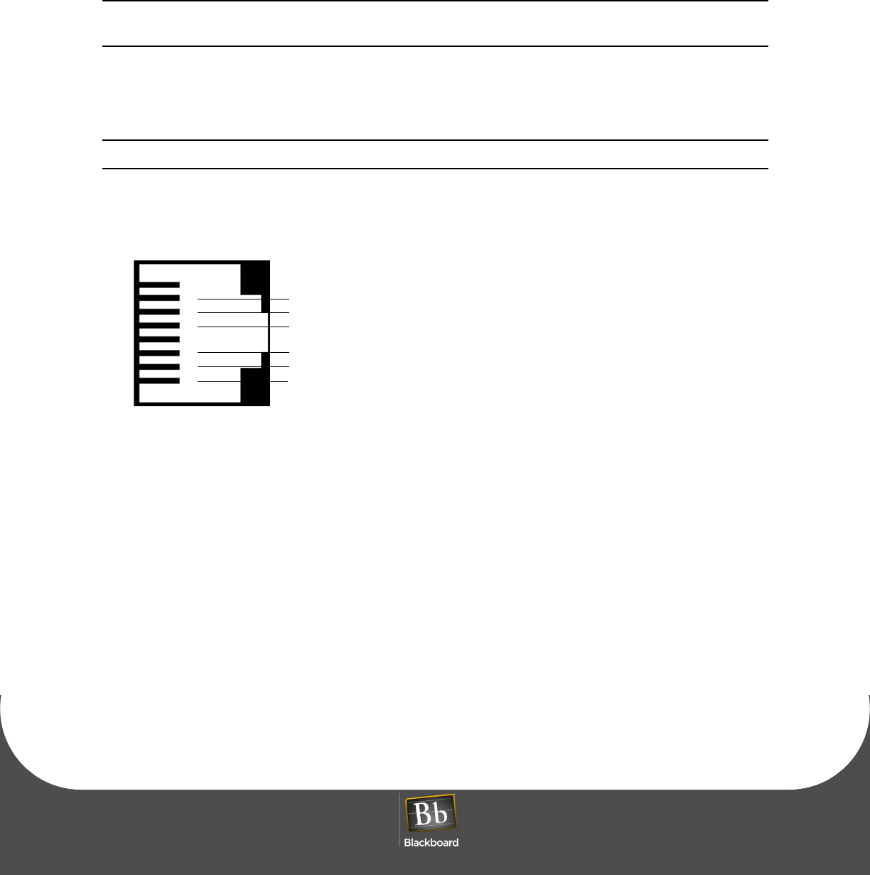
Figure 1-4 RS-485 Reader Pinout
1
2
3
4
5
6
7
8
RS-485 HOST Port and RJ-45 wall plate wiring
(Ground)
Receive (RX+)
Transmit (TX+)
Receive (RX-)
(Ground)
Transmit (TX-)

AC3100 COMMUNICATION CONFIGURATION
PRINTED APRIL 14, 2011 8
AC3100 COMMUNICATION CONFIGURATION
NOTE: The AC3100 must be configured at the host before continuing. For more information,
see: The Transaction System Administration Guide, and the BbTS UNIX Edition Reference
Manual.
The AC3100 must be configured with communication parameters using one of three configuration
methods:
•Front Panel (initiated by a service card)
See: Configure Communication using Front Panel & Service Card (page 1-10)
•RS-232 using a terminal (i.e. computer, HyperTerminal software, and configuration cable)
See: Configure Communication using RS-232 or Telnet (page 1-11)
•Telnet via IP using an ethernet connection.
See: Configure Communication using RS-232 or Telnet (page 1-11)
NOTE: If this device accepts credit cards, Telnet must be disabled to meet PCI compliance.
AC3100 INSTALLATION GUIDE
DOCUMENT 1353 REV 01
PRINTED APRIL 14, 2011 9
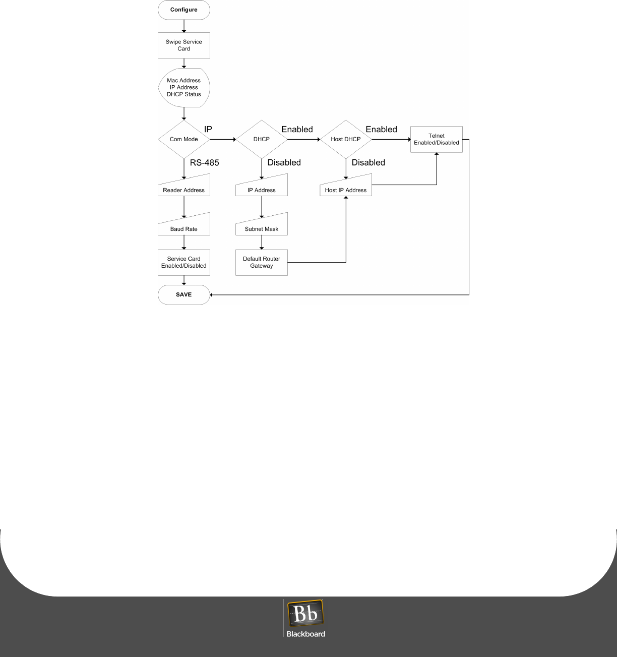
Figure 1-5 Configuration Flowchart
AC3100 COMMUNICATION CONFIGURATION
PRINTED APRIL 14, 2011 10
Configure Communication using Front Panel & Service Card
To configure communication using front panel & service card
1Swipe the specially encoded service card, and then press NEXT.
2Configure each of the setup parameters, as appropriate, using the keys and display prompts.
ACCEPT - Accept displayed value and advance to next setting.
CHANGE - Change displayed value.
ABORT - Abort configuration process.
To update the IP address and related information, press CHANGE when the parameter displays, and
then type in the number using zeroes (0) as placeholders.
3Press SAVE when prompted to save the new settings, and then reboot the AC3100.
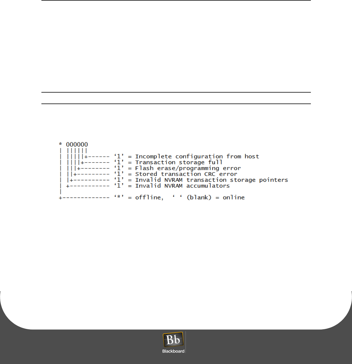
NOTE: Temporarily Out of Service displays until communication is established with the host.
Figure 1-6 Out-Of-Service Codes
The 'Temporarily Out of Service' screen displays the out-of-service codes in the lower-left portion of
the screen.
AC3100 INSTALLATION GUIDE
DOCUMENT 1353 REV 01
PRINTED APRIL 14, 2011 11
Configure Communication using RS-232 or Telnet
To configure communication using RS-232 or Telnet
1If using RS-232, connect a configuration cable between the config port on the AC3100 and the COM
port. For cable pinout, see: Configuration Cable Pinout (page 1-11).
2Open a Terminal Program (RS-232 or Telnet).
3Set the following connection settings for RS-232.
9600 baud
1 stop
no parity
no flow control
4Login using the default password: IPrdr4U.
The password is case sensitive.
5Type config, and then press Enter at the prompt.
Set the configuration settings using the commands listed below.
Table 1-2: Configuration Cable Pinout
CONFIG Port (RJ-12) PC Serial Port
DB9 Connector Signal
Pin 1 Pin 5 Ground
Pin 3 Pin 3 Receive (RX)
Pin 4 Pin 2 Transmit (TX)

AC3100 COMMUNICATION CONFIGURATION
PRINTED APRIL 14, 2011 12
Figure 1-7 Configuration Command Reference
Command Reference
config - Configure network parameters
showconfig - Display current configuration
status - Display reader status
ping <ip_addr> - Ping another IP device
netstats - Display network statistics
netclear - Clear network statistics counters
password - Change config utility password
ipreboot - Reboot reader
exit - Log out of session
Type command, followed by ‘Enter’ key >

AC3100 INSTALLATION GUIDE
DOCUMENT 1353 REV 01
PRINTED APRIL 14, 2011 13
AC3100 TRANSACTION PROCESS
NOTE: Load paper and cards prior to performing transactions, see: AC3100 Maintenance
(page 15).
Perform test transactions to verify proper operation of deposits, visitor card purchases, and account
balance checks.
Deposit Funds to an Existing Account
To deposit funds to an existing account
1Select Deposit Funds from the on-screen menu.
NOTE: The actual verbiage of this prompt is determined by the host configuration.
2Follow the on-screen prompts to complete the transaction.
Purchase a Visitor Card
To purchase a visitor card
1Select Purchase Visitor Card from the on-screen menu.
NOTE: The actual verbiage of this prompt is determined by the host configuration.
2Follow the on-screen prompts to complete the transaction.
Check Account Balance
To check account balance
1Select Check Account Balance from the on-screen menu.
2Follow the on-screen prompts to complete the transaction.

AC3100 MANAGER CARD FUNCTIONS
PRINTED APRIL 14, 2011 14
AC3100 MANAGER CARD FUNCTIONS
Certain Cards can be configured as Manager Cards in BbTS. Inserting/removing a valid Manager Card
when the AC3100 is in the idle mode (not in a transaction sequence), displays the manager card menu.
Manager functions:
Display/print transaction totals
This option displays and prints transaction totals. It is intended to be used to create a local Audit report on
the transactions each time the bill box is emptied or swapped out with an empty one.
When totals display on the LCD, the manager has the option of clearing the interval totals. If the bills are
being removed, it is recommended to clear the totals and attach a copy of the Audit printout with the bills
for later audit.
These totals can be displayed/printed and not cleared if desired. If multiple copies of the audit printout are
desired, the totals can be displayed/printed several times and only clearing them the last time.
Terminal setup
This option is used to adjust the display brightness and the volume of the tones.
Display device status information
This option displays the AC3100 status information. The display includes information on the
communication status with the host (on-line of off-line, etc.), any out-of-service conditions and status of the
printer, bill validator, and card dispenser.
Perform diagnostic functions
This option is used to perform diagnostic functions on the LCD, card dispenser, printer, local alarm and
door switch, and the keypads.
AC3100 INSTALLATION GUIDE
DOCUMENT 1353 REV 01
PRINTED APRIL 14, 2011 15
AC3100 MAINTENANCE
AC3100 maintenance tasks include:
•Fill the Card Dispenser (page 1-15)
•Empty the Bill Box (page 1-15)
•Install the Paper Roll (page 1-17)
•Replace the Power Supply Fuses (page 1-20)
NOTE: The AC3100 contains a configurable local alarm. The alarm sounds when the door is
opened without an authorized manager card swipe, see: AC3100 Components (page 1-21).
Fill the Card Dispenser
To fill the card dispenser
1Remove the metal H shaped weight from the card dispenser chute.
For location, see: AC3100 Components (page 1-21).
2Load the cards into the card dispenser chute, and then replace the metal weight on top of the stack of
cards.
NOTE: Use only .030" PVC cards. The dispenser can hold approximately 190 cards.
Empty the Bill Box
Bills can only be removed from the Bill Validator by removing the Bill Box.
For location, see: AC3100 Components (page 1-21).
NOTE: Although the Bill Validator can hold up to 1000 bills, a maximum currency value can
also be set. Once either limit is reached, cash deposits are no longer allowed.
There are two keys used with the Bill Box:
•A042 Key - Opens the Bill Box. (All Keyed alike)
•A043 Key - Releases the Bill Box from the Bill Validator. (All keyed alike)
AC3100 MAINTENANCE
PRINTED APRIL 14, 2011 16
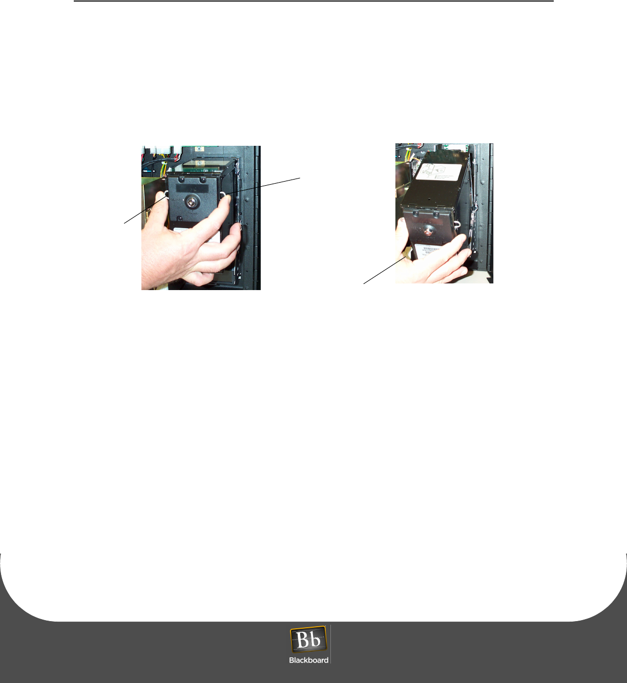
To empty the Bill Box
1With the enclosure open, insert the A043 key, and then turn key counter-clockwise to unlock the Bill
Box from the Bill Validator.
2Press the two wire releases to disengage the latch, and then pivot the Bill Box away from the Bill
Validator, by gently pulling at the top.
The bill box can now be lifted straight up to disengage the hinge pins from the Bill Validator bracket.
The wire releases free the Bill Box from the cassette.
Figure 1-8 Bill Box Removal
3Insert the A042 key into the lock located in the rear of the Bill Box, and then turn counter-clockwise.
4Open the Bill Box door.
Remove the currency.
5To reinstall, engage pivot pins, and then push forward until the Bill Box latches.
Wire
Wire Release
Release
Pivot the Bill Box
away from the door
AC3100 INSTALLATION GUIDE
DOCUMENT 1353 REV 01
PRINTED APRIL 14, 2011 17
Install the Paper Roll
NOTE: When installing a paper roll for the first time, the tape securing the print head to the
printer body must be removed and discarded. The tape protects the print head from damage
during shipping.
A Low Paper sensor located on the printer assembly alerts the administrator when this
condition occurs. This information can be sent to a log file. The paper can be changed without
access to the cash.
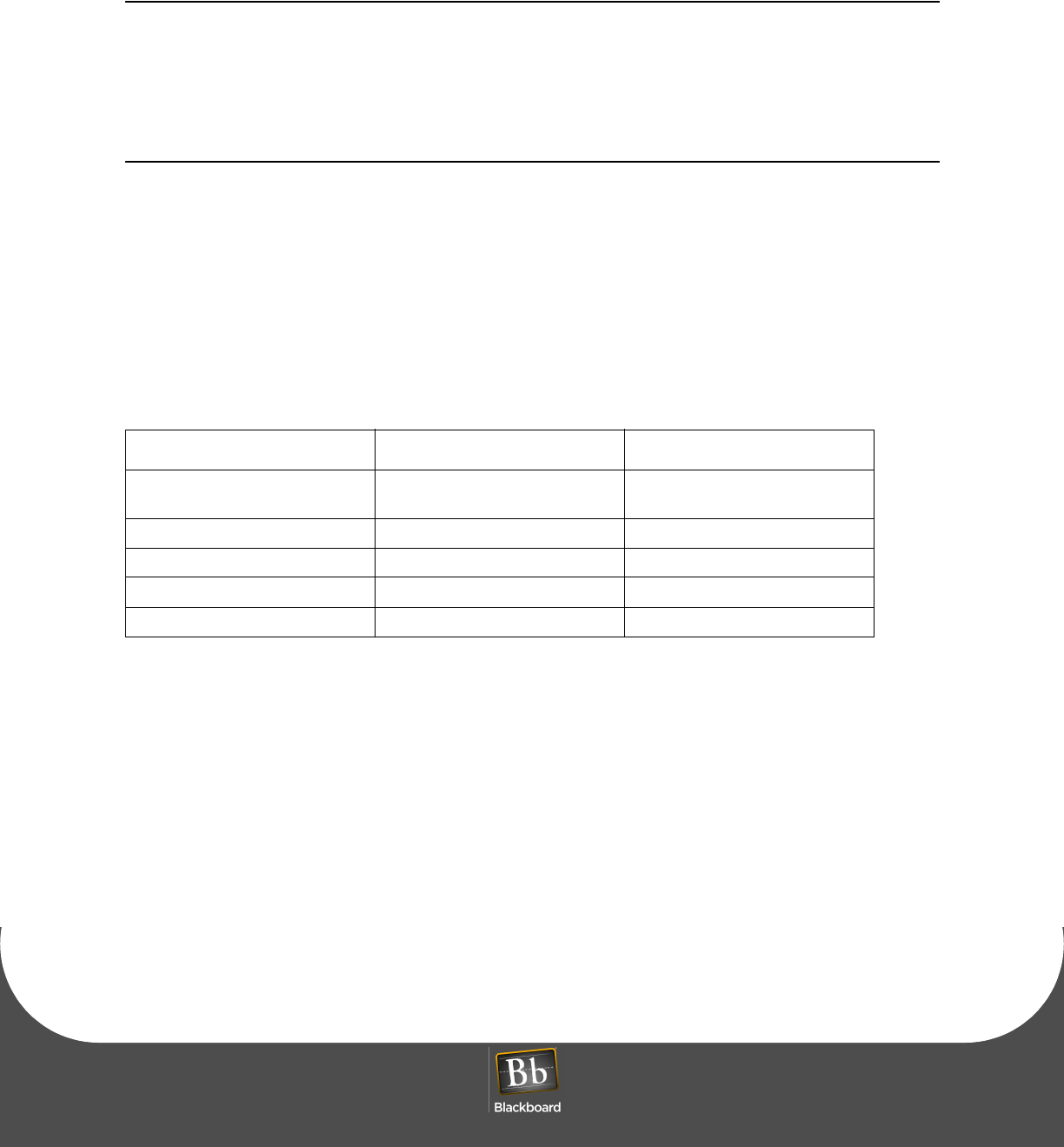
The AC3100 printer uses thermal paper with the following specifications:
• 80mm-wide
• 20# or 21# paper weight
• Maximum 6” OD
• 1” ID core
• Thermally coated side OUT
Table 1-3: Paper Roll Sources
Supplier Part Number Phone Number(s)
Communication Paper Ltd. Inc. CP-80715 (Superior Grade 20#) phone (888) 327-2737
fax (908) 713-6313
Current Components TP80-6-354 (800) 342-9798
Max International T2318645-8 (800) 233-0222 ext. 105
Printing Technologies TTP7080 (800) 428-3786
Swecoin SWE80-150 (401) 734-6709
AC3100 MAINTENANCE
PRINTED APRIL 14, 2011 18
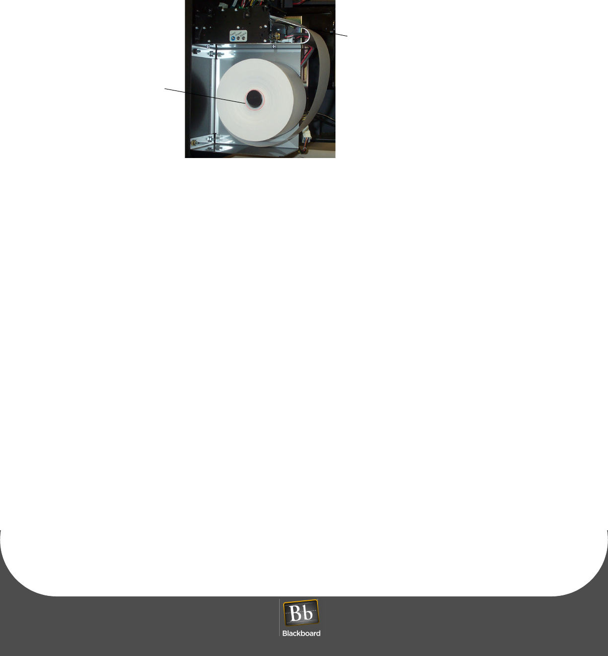
To install the paper roll
1Turn the new paper roll as shown.
Insert the paper roll into the printer with the temperature-sensitive side up.
Figure 1-9 AC3100 Paper roll
2Remove a full turn of the paper from the new paper roll.
NOTE: This is important since the outer end of the paper is usually fixed to the roll with glue
or self-adhesive substance that can cause a paper jam or print head damage.
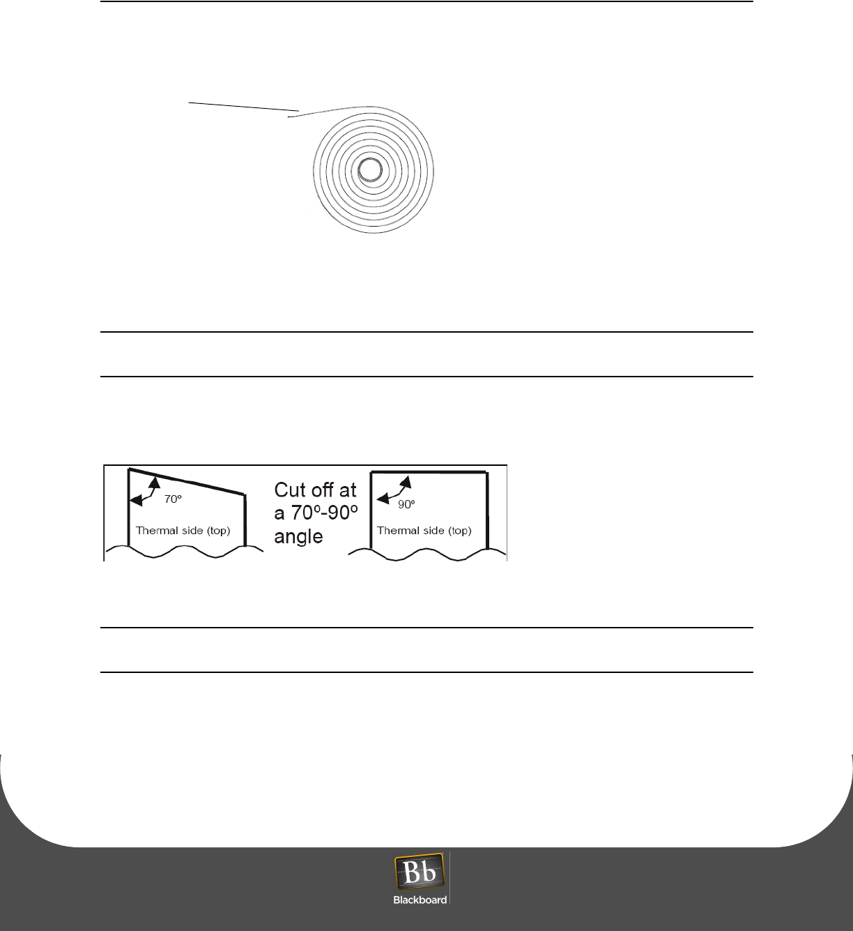
3Cut the paper off at a 70 to 90 degree angle as shown.
Figure 1-10 Paper Roll Cut-off
NOTE: If the paper is cut in the opposite direction to what is shown in Figure 1-10, the printer
may not detect the paper.
4Insert the paper through the paper entry opening at the back of the printer.
The printer feeds, cuts and ejects a printout, and then goes on-line.
temperature
sensitive
side up
AC3100 INSTALLATION GUIDE
DOCUMENT 1353 REV 01
PRINTED APRIL 14, 2011 19
Figure 1-11 Paper Entry Opening
feed the
paper
place over the end of
the spool to secure
COMPONENT REPLACEMENT
PRINTED APRIL 14, 2011 20
COMPONENT REPLACEMENT
Replace the Power Supply Fuses
WARNING: To eliminate risk of electrical shock or injury, it is recommended that the main
115VAC supply or breaker be turned off and the power switch on the AC3100 power supply
is turned off!
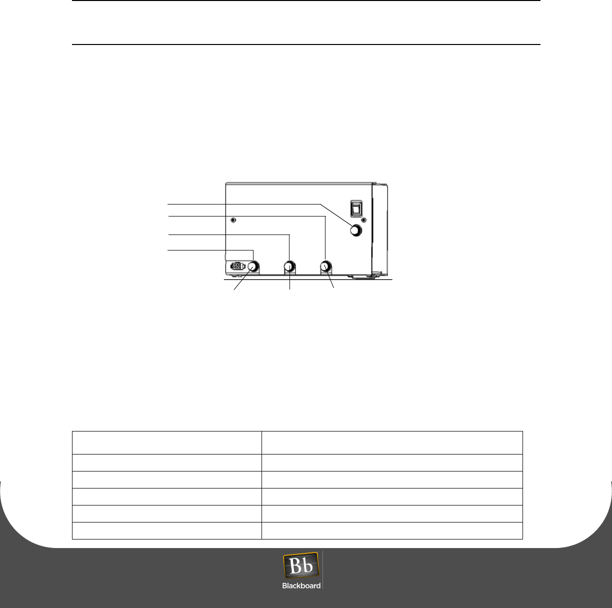
The AC3100 uses a single 1A 250v fuse for input power and three 3A 250V fuses for output power. The
power input fuse is located directly below the on/off power switch. The output fuses are located across the
bottom of the power supply module. The fuse on the left is for +12v output which supplies power to the
electronics board, LCD, and mag-stripe reader. The center fuse is +24v power for the printer. The right fuse
is +24v power for the bill validator and card dispenser. If a peripheral is not functioning, check the fuse and
replace if necessary.
Figure 1-12 AC3100 Fuse Locations
FIELD REPLACEMENT COMPONENTS
When ordering replaceable parts for the AC3100, refer to the table below and contact Blackboard.
Table 1-4: AC3100 Replacement Parts
MSC Part Number Description
MSC/BVACUS Replacement Bill Validator for United States currency
MSC/BVACCA Replacement Bill Validator for Canadian currency
MSC/RPAC Replacement Printer
MSC/CDAC Replacement Card Dispenser
MSC/RDRAC2 Replacement Contactless/Mag-stripe reader
3AG 3A 250V
3AG 1A 250V
3AG 3A 250V
3AG 3A 250V
Power Supply
CONTROLLER/LCD
& MAG-STRIPE READER
PRINTER Bill Validator &
Card Dispenser
COMPONENT REPLACEMENT
PRINTED APRIL 14, 2011 21
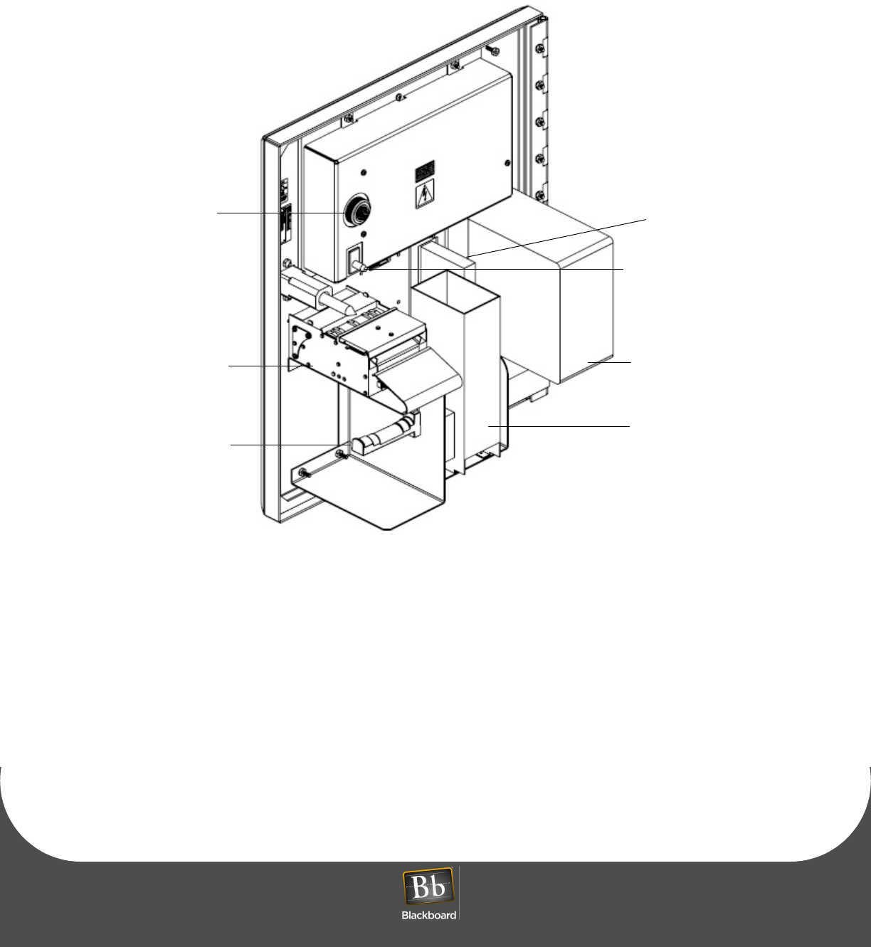
Figure 1-13 AC3100 Components
Printer
Assembly
Bill
Box
Tamper Switch
Card Dispenser
Card
Reader
Paper Roll
SIREN
(Sets off Siren)
Spool
COMPONENT REPLACEMENT
PRINTED APRIL 14, 2011 22
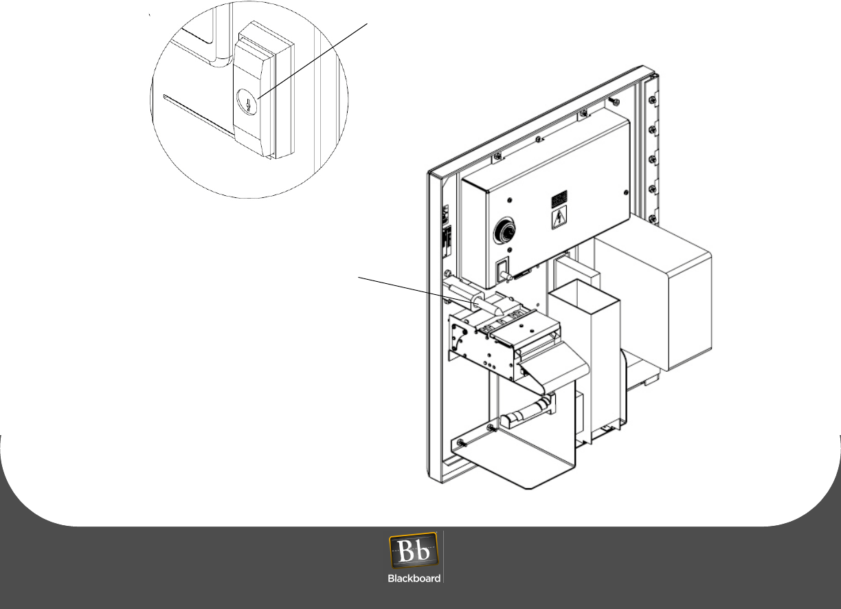
LOCK LUBRICATION
• The AC3100 requires lubrication of the lock mechanism
• Apply lubricant anytime an increase in torque is required to turn the lock
• Lubricate the threaded rod on the lock mechanism with a silicone-based grease (comparable to SIL-GLYDE)
• Apply the grease to the first 3 threads at the end of the rod
• Lubricate the lock cylinder with a spray type lubricant (Teflon based such as Tri-Flow)
• Close the door of the AC3100 to avoid any overspray coming into contact with electrical components
• Position the spray nozzle close to the lock cylinder, and then apply a small amount
• Install the key in the lock cylinder, and then turn several times to disperse the lubricant
• Wipe off any excess from the lock handle and surrounding area
• Lubricate the hinge with a spray type lubricant (Teflon based such as Tri-Flow)
• Position the spray nozzle close to the hinge and apply a small amount, avoid any overspray coming into
contact with electrical components
Figure 1-14 Lock Lubrication
Lubricate lock with Tri-Flow or similar lubricant
Lubricate lock screw with SIL-GLYDE
or similar lubricant

AC3100 FEATURES & SPECIFICATIONS
PRINTED APRIL 14, 2011 23
AC3100 FEATURES & SPECIFICATIONS
AC3100 Features:
• Accepts unattended deposits
• Purchase and dispense visitor cards
• Check account balances
• Print receipts
• 8.4” color LCD display
• Configurable text colors, background colors, and color banners
• Optionally charge a fee for card purchases
• Configurable to accept $1, $5, $10, $20, $50, $100 bill denominations
• Accepts Credit cards (Universal Edition only)
• Local audit report capability
• Remote software downloads
• Lockable bill boxes (load printer paper or cards without access to cash)
• Advanced Encryption Standard (AES) for IP
• Local tamper siren
• Contact your Account Manager for a template to design a front cover decal used for marketing
AC3100 Specifications:
NOTE: This device contains an integrated lithium battery. There is a risk of fire if the battery is
replaced with an incorrect type. Proper disposal of a used battery is essential. Please follow
the manufacturer’s instructions.
Physical Size: 18"W x 21"H x 9.775"D (10.145"D including bezel) 80 pounds
Input Power: 120 VAC Max @ 60Hz, 1.5 amp max
Operating: Temperature: 0 to +50 degrees Celsius
Relative Humidity: 0 to 96 percent, non-condensing
Altitude: 0 - 10,000 feet
Non-Operating: Temperature: -20 to +70 degrees Celsius
Relative Humidity: 0 to 95 percent, non-condensing
Altitude: 0 - 35,000 feet

BBTS UNIVERSAL EDITION CHANGES
PRINTED APRIL 14, 2011 24
BBTS UNIVERSAL EDITION CHANGES
When converting an AC3100 from Unix Edition to Universal Edition, the following items are affected:
•Privileges - Do not function the same as they do in Unix Edition, every cardholder that uses a reader
in a particular Profit Center is required to use the same fund Autostored Value Order
•Plan Level Discounts - Do not currently work in UE
•Shadow Accounts - Do not currently work in UE