Transact Campus LWI30XX002 900 MHz Wireless Module User Manual LC3000 Install 2 9
Blackboard Inc. 900 MHz Wireless Module LC3000 Install 2 9
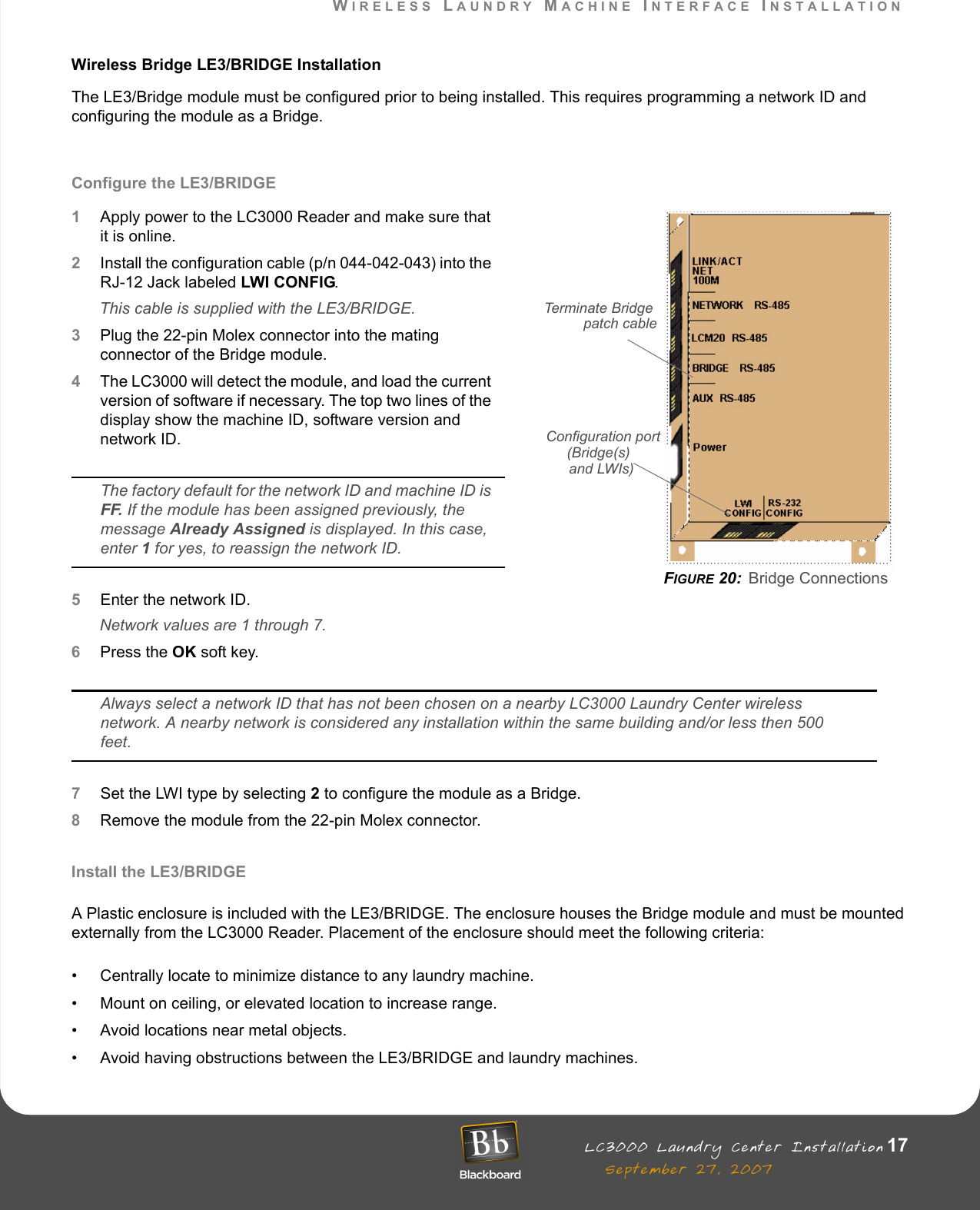
UserManual.wiki
>
Transact Campus
>
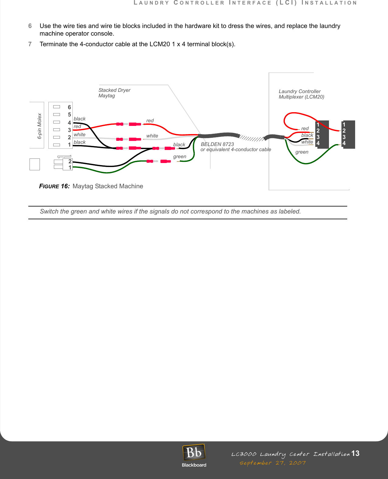
LWI30XX002 User Manual
Users Manual
Navigation menu
Upload a User Manual
Namespaces
Wiki Guide
HTML
PDF
Info
Views
User Manual
Discussion / Help
Navigation