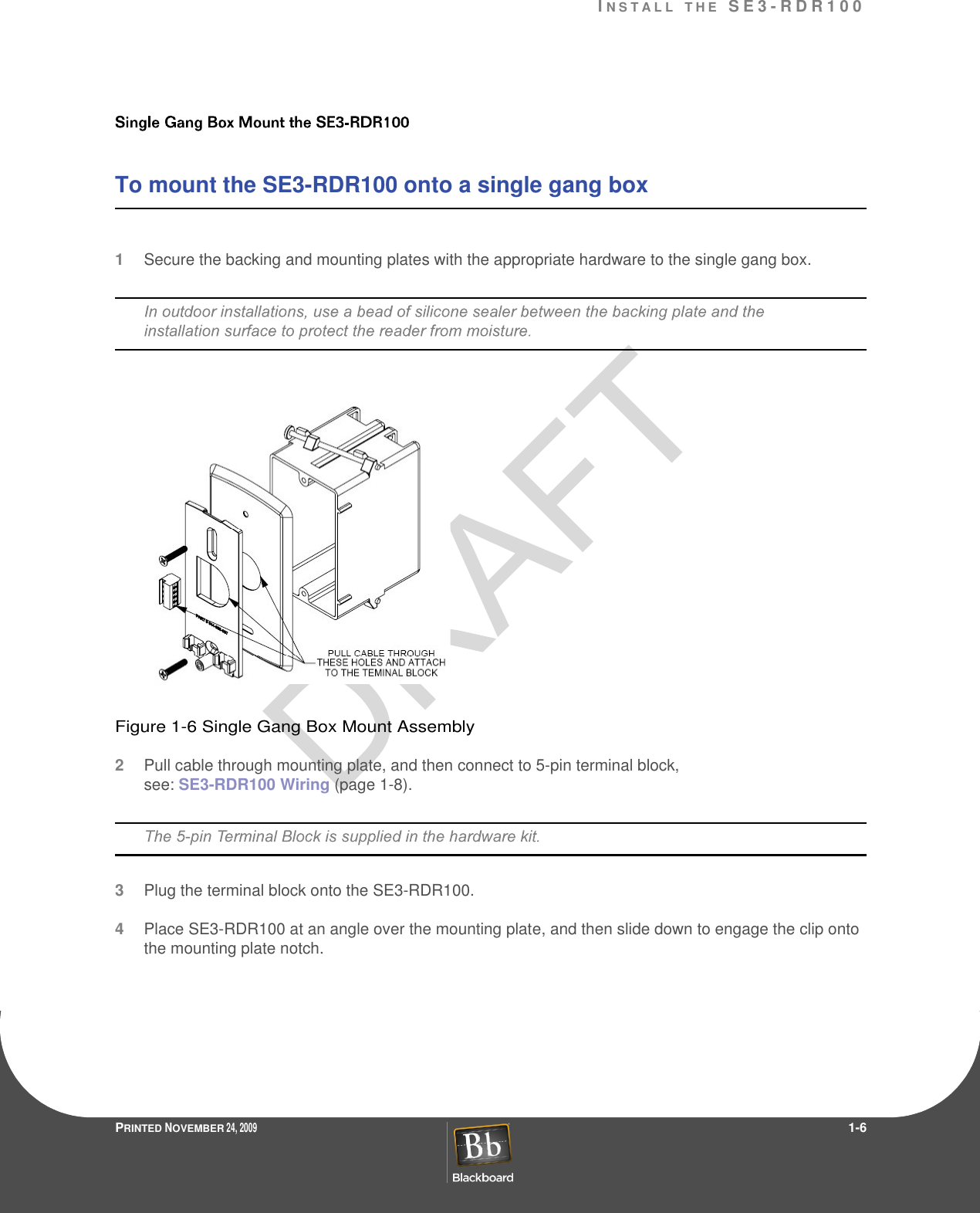
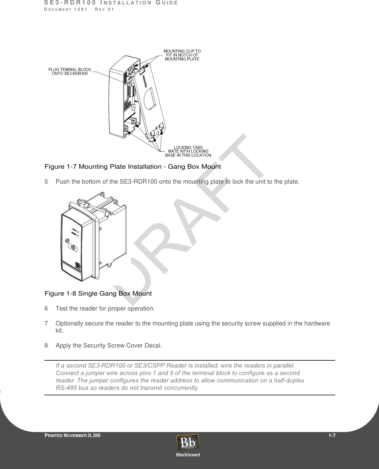
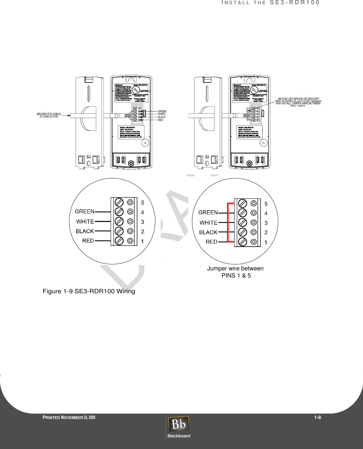
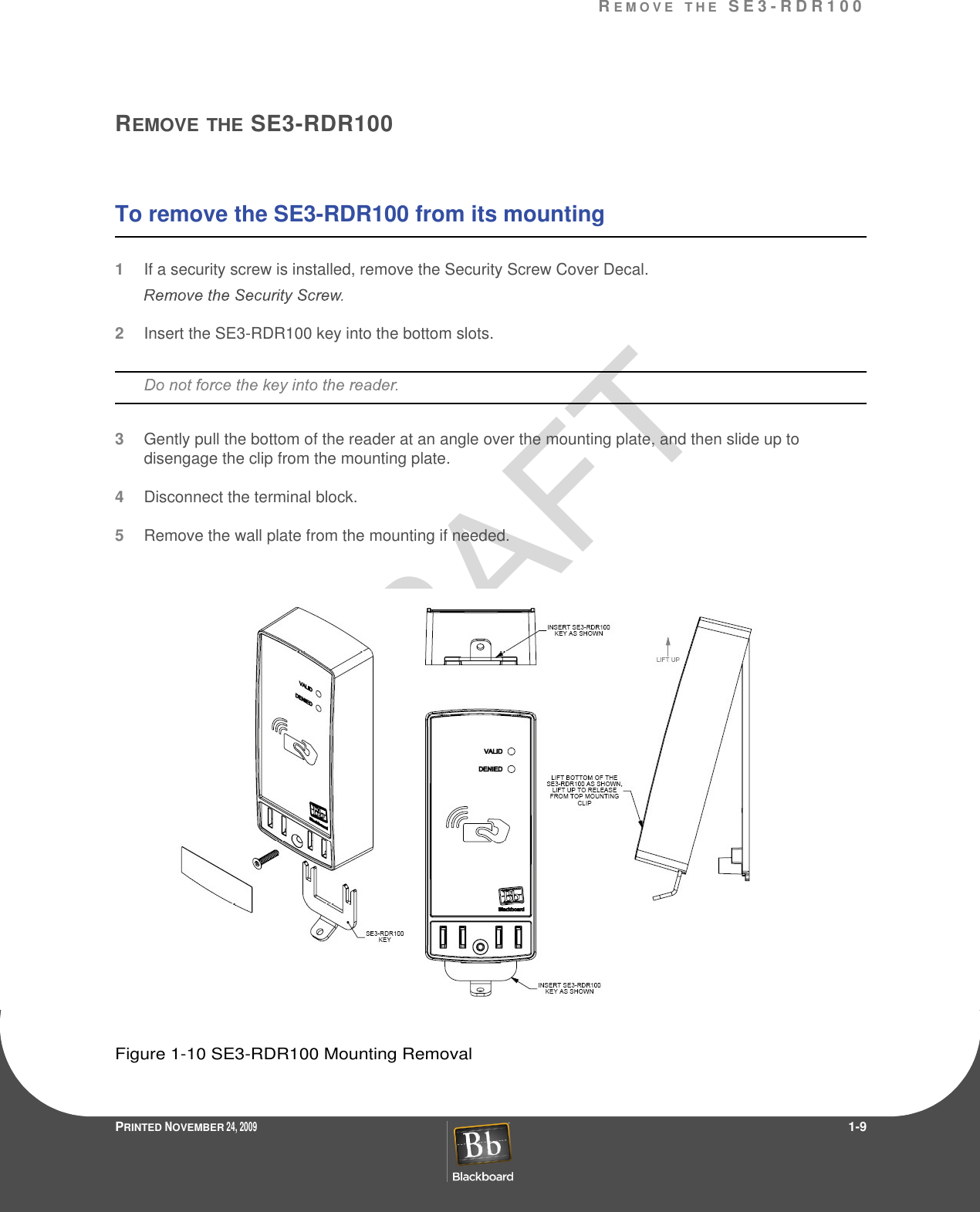
Transact Campus SE3100X006 Card Reader User Manual 1291 SE3RDR100 Install DRAFTf

Blackboard Inc. Card Reader 1291 SE3RDR100 Install DRAFTf

Contents

User Manual 1

ContentsPRINTED NOVEMBER 24, 2009                 I2SE3-RDR100 INSTALLATION GUIDE3 Install the SE3-RDR1003 Surface Mount the SE3-RDR1006 Single Gang Box Mount the SE3-RDR1009 Remove the SE3-RDR10010 Specifications
FiguresPRINTED NOVEMBER 24, 2009                 IIFigure 1-1 SE3-RDR100 Reader.................................................................................2Figure 1-2 Mounting Drill Pattern.................................................................................3Figure 1-3 Mounting Plate Installation - Mullion...........................................................4Figure 1-4 Mounting Plate Installation - Surface Mount...............................................5Figure 1-5 Mullion Installation......................................................................................5Figure 1-6 Single Gang Box Mount Assembly.............................................................6Figure 1-7 Mounting Plate Installation - Gang Box Mount...........................................7Figure 1-8 Single Gang Box Mount .............................................................................7Figure 1-9 SE3-RDR100 Wiring ..................................................................................8Figure 1-10 SE3-RDR100 Mounting Removal...............................................................9
S E 3 - R D R 1 0 0  I N S T A L L A T I O N  GU I D EDO C U M E N T  1 2 9 1    R E V  0 1PRINTED NOVEMBER 24, 2009                 1-1This device complies with Part 15 of the FCC Rules. Operation is subject to the following two conditions: (1) This device may not cause harmful interference, and (2) this device must accept any interference received, including interference that may cause undesired operation. Part 15.21: Changes or modifications not expressly approved by the party responsible for compliancrity to operate the equipment.NOTE:The manufacturer is not responsible for any radio or TV interference caused by unauthorized modifications to this equipment. This equipment complies with the FCC radiation exposure limits set forth for an uncontrolled environment. End users must follow the specific operating instructions for satisfying RF exposure compliance. The antenna(s) used for this transmitter must be installed to provide a separation distance of at least 20 cm from all persons and must not be co-located or operating in conjunction with any other antenna or transmitter.Blackboard Inc. SE3-RDR100Tested To ComplyWith FCC StandardsFOR HOME OR OFFICE USEThis Class B digital apparatus complies with Canadian ICES-003Cet appareill numérique de la classes B est conform à la norme NMB-003 du Canada
PRINTED NOVEMBER 24, 2009                 1-2SE3-RDR100  INSTALLATION  GUIDEThe Blackboard SE3-RDR100 is a Door Access Reader that supports contactless card technology. Contactless Card Technology offers the following advantages vs. magnetic stripe:virtually eliminates reader wear and tear (card need not contact the reader)Figure 1-1 SE3-RDR100 ReaderThe SE3-RDR100 Card Reader may be mounted or a single gang box using the included backing plate.The following items are included with the SE3-RDR100:
S E 3 - R D R 1 0 0  I N S T A L L A T I O N  GU I D EDO C U M E N T  1 2 9 1    R E V  0 1PRINTED NOVEMBER 24, 2009                 1-3INSTALLTHE SE3-RDR100UL Considerations:Attention to Installers: All field wiring/cabling connections made to the Controller need to use shielded cable with one of the shielded ends connected to earth ground.Surface Mount the SE3-RDR100 (page1-3)Single Gang Box Mount the SE3-RDR100 (page1-6)The mounting plate is secured using #6 flat head hardware. Select hardware based on the mounting material.To surface mount the SE3-RDR1001Use the mounting plate as a template to mark mounting holes and a cable routing hole.2Drill the holes for the mounting hardware (#6 flathead screws) and the cable.Figure 1-2 Mounting Drill Pattern
IN S T A L L T H E  S E 3 - R D R 1 0 0PRINTED NOVEMBER 24, 2009                 1-43Secure the mounting plate with the chosen hardware.Figure 1-3 Mounting Plate Installation - Mullion4Pull the cable through the hole, and then wire to the 5-pin terminal block.SE3-RDR100 Wiring 5Plug the terminal block onto the SE3-RDR100.6Place SE3-RDR100 at an angle over the mounting plate, and then slide down to engage the clip onto the mounting plate notch.
S E 3 - R D R 1 0 0  I N S T A L L A T I O N  GU I D EDO C U M E N T  1 2 9 1    R E V  0 1PRINTED NOVEMBER 24, 2009                 1-5Figure 1-4 Mounting Plate Installation - Surface Mount7Push the bottom of the reader onto the mounting plate to lock the unit to the plate.Figure 1-5 Mullion Installation8Test the SE3-RDR100 for proper operation.9Optionally secure the reader to the mounting plate using the security screw supplied in the hardware kit.10Apply the Security Screw Cover Decal.
IN S T A L L T H E  S E 3 - R D R 1 0 0PRINTED NOVEMBER 24, 2009                 1-6To mount the SE3-RDR100 onto a single gang box 1Secure the backing and mounting plates with the appropriate hardware to the single gang box.Figure 1-6 Single Gang Box Mount Assembly2Pull cable through mounting plate, and then connect to 5-pin terminal block, see: SE3-RDR100 Wiring (page 1-8).3Plug the terminal block onto the SE3-RDR100.4Place SE3-RDR100 at an angle over the mounting plate, and then slide down to engage the clip onto the mounting plate notch.
S E 3 - R D R 1 0 0  I N S T A L L A T I O N  GU I D EDO C U M E N T  1 2 9 1    R E V  0 1PRINTED NOVEMBER 24, 2009                 1-7Figure 1-7 Mounting Plate Installation - Gang Box Mount5Pushthe bottom of the SE3-RDR100 onto the mounting plate to lock the unit to the plate.Figure 1-8 Single Gang Box Mount6Test the reader for proper operation.7Optionally secure the reader to the mounting plate using the security screw supplied in the hardware kit.8Apply the Security Screw Cover Decal.
IN S T A L L T H E  S E 3 - R D R 1 0 0PRINTED NOVEMBER 24, 2009                 1-8Figure 1-9 SE3-RDR100 WiringJumper wire between PINS 1 & 5
RE M O V E T H E  S E 3 - R D R 1 0 0PRINTED NOVEMBER 24, 2009                 1-9REMOVETHE SE3-RDR100To remove the SE3-RDR100 from its mounting1If a security screw is installed, remove the Security Screw Cover Decal.2Insert the SE3-RDR100 key into the bottom slots.3Gently pull the bottom of the reader at an angle over the mounting plate, and then slide up to disengage the clip from the mounting plate.4Disconnect the terminal block.5Remove the wall plate from the mounting if needed.Figure 1-10 SE3-RDR100 Mounting Removal
SP E C I F I C A T I O N SPRINTED NOVEMBER 24, 2009                 1-10SPECIFICATIONSPhysical Size:  Weight: 0.30 lbsInput Power:  12VDC 150mA, 1.8 Watts MaximumOperating:  Temperature: -20 to 60+ degrees CelsiusRelative Humidity: 0 to 95 percent, non-condensingAltitude: 0 - 10,000 feetNon-Operating:  Temperature: -20 to +70 degrees CelsiusRelative Humidity: 0 to 95 percent, non-condensingAltitude: 0 - 35,000 feetThis device contains an integrated lithium battery (BR2032). There is a risk of fire if the battery is replaced with an incorrect type. Proper disposal of a used battery is essential.

Navigation menu