Transact Campus SE3100X006 Card Reader User Manual 2
Blackboard Inc. Card Reader 2
Contents
- 1. User Manual 1
- 2. User manual 2
User manual 2
Certificates and reports shall not be reproduced except in full, without the written permission of Washington Laboratories, Ltd.
FCC and Industry Canada Certification Test Report
For the
SkyBitz, Inc.
MTXM L-Band Mobile Terminal
FCC ID: SAE-000MTXM
IC ID: 5375A-000MTXM
WLL REPORT# 11125-01 Rev 3
November 11, 2009
Re-issued November 12, 2009
Re-issued November 17, 2009
Re-issued December 3, 2009
Prepared for:
SkyBitz, Inc.
22455 Davis Drive Suite 100
Sterling, Virginia 20164
Prepared By:
Washington Laboratories, Ltd.
7560 Lindbergh Drive
Gaithersburg, Maryland 20879
Testing Certificate 2675.01
Skybitz Inc
MTXM
FCC/IC Test Report
November, 2009
WLL Report #11125-01 Rev. 3 - ii - © 2009 Washington Laboratories, Ltd
FCC and Industry Canada Certification Test Report
For the
SkyBitz, Inc.
MTXM L-Band Mobile Terminal
FCC ID: SAE-000MTXM
IC ID: 5375A-000MTXM
WLL REPORT# 11125-01 Rev 3
November 11, 2009
Re-issued November 12, 2009
Re-issued November 17, 2009
Re-issued December 3, 2009
Prepared by:
John P. Repella
Compliance Engineer
Reviewed by:
Steve Koster
EMC Operations Manager
Skybitz Inc
MTXM
FCC/IC Test Report
November, 2009
WLL Report #11125-01 Rev. 3 - iii - © 2009 Washington Laboratories, Ltd.
Abstract
This report has been prepared on behalf of SkyBitz, Inc. to support the attached Application for
Equipment Authorization. The test report and application are submitted for a Satellite Terminal under
Part 25 of the FCC Rules and Regulations and under the Regulations and Spectrum Management and
Telecommunications Policy RSS-170 of Industry Canada. This Certification Test Report documents
the test configuration and test results for a SkyBitz, Inc. MTXM L-Band Mobile Terminal.
Testing was performed on an Open Area Test Site (OATS) of Washington Laboratories, Ltd, 7560
Lindbergh Drive, Gaithersburg, MD 20879. Site description and site attenuation data have been placed
on file with the FCC's Sampling and Measurements Branch at the FCC laboratory in Columbia, MD.
The Industry Canada OATS numbers are 3035A-1 and 3035A-2 for Washington Laboratories, Ltd. Site
1 and Site 2, respectively. Washington Laboratories, Ltd. has been accepted by the FCC and approved
by the American Association for Laboratory Accreditation (A2LA) under Certificate 2675.01 as an
independent FCC test laboratory.
The SkyBitz, Inc. MTXM L-Band Mobile Terminal complies with the technical requirements under
FCC Part 25 and Industry Canada RSS-170.
Revision History Reason Date
Rev 0
I
nitial Release November 11, 2009
Rev 1
C
orrect customer address and
e
missions type
November 12, 2009
Rev 2
R
X and TX Frequency Ranges added to
t
he Device Summary Table 1
November 17, 2009
Rev 3
A
ddress ATCB Comments to add
N
ecessary BW and V I of final amp
December 3, 2009

Skybitz Inc
MTXM
FCC/IC Test Report
November, 2009
WLL Report #11125-01 Rev. 3 - iv - © 2009 Washington Laboratories, Ltd.
Table of Contents
Abstract....................................................................................................................................................... ii
1 Introduction......................................................................................................................................1
1.1 Compliance Statement .................................................................................................................1
1.2 Test Scope....................................................................................................................................1
1.3 Contract Information....................................................................................................................1
1.4 Test Dates ....................................................................................................................................1
1.5 Test and Support Personnel .........................................................................................................1
1.6 Abbreviations...............................................................................................................................2
2 Equipment Under Test .....................................................................................................................3
2.1 EUT Identification & Description ...............................................................................................3
2.2 Test Configuration .......................................................................................................................3
2.3 Testing Algorithm........................................................................................................................4
2.4 Test Location ...............................................................................................................................5
2.5 Measurements ..............................................................................................................................5
2.6 Measurement Uncertainty............................................................................................................5
3 Test Equipment ................................................................................................................................6
4 Test Results......................................................................................................................................7
4.1 RF Power Output (FCC 25.204, RSS-170 Section 6.2)...............................................................7
4.2 Occupied Bandwidth....................................................................................................................9
4.3 Emission Limitations per FCC Part 25.202(f); RSS-170 Section 6.3 (Emission Masks) .........13
4.4 Radiated Spurious Emissions: EIRP Data (FCC §25.202(f) and RSS-170, Annex B3) ...........20
4.5 Receiver Spurious Emissions, RSS-170 Section 9.0 .................................................................23
4.6 Spurious Emissions per FCC §25.216 .......................................................................................24
4.7 Frequency Stability: (FCC Part §2.1055) ..................................................................................39
List of Tables
Table 1: Device Summary ...........................................................................................................................3
Table 2: Test Equipment List.......................................................................................................................6
Table 3: RF Power Output ...........................................................................................................................8
Table 4: Occupied Bandwidth Results.........................................................................................................9
Table 5: Table B1 of RSS-170...................................................................................................................13
Table 6: Radiated Emissions......................................................................................................................21
Table 7: Frequency Stability Test Data .....................................................................................................40

Skybitz Inc
MTXM
FCC/IC Test Report
November, 2009
WLL Report #11125-01 Rev. 3 - v - © 2009 Washington Laboratories, Ltd.
List of Figures
Figure 1: Test Setup Diagram......................................................................................................................4
Figure 2: Occupied Bandwidth, Low Channel, TX @ 1626.505MHz ......................................................10
Figure 3: Occupied Bandwidth, Mid Channel, TX @ 1643.5MHz...........................................................11
Figure 4: Occupied Bandwidth, High Channel, TX @ 1660.495MHz .....................................................12
Figure 5: FCC Part 25.202(f) Emissions Mask, Vertical Polarity.............................................................15
Figure 6: FCC Part 25.202(f) Emissions Mask, Horizontal Polarity.........................................................16
Figure 7: Out-of-Band Emissions to Table B1 ..........................................................................................17
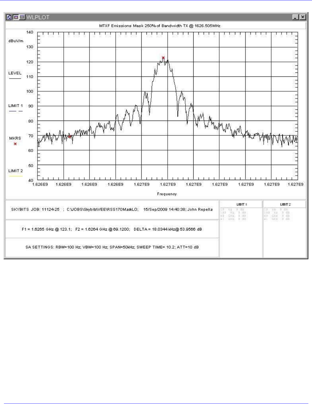
Figure 8: Spectrum Plot, Low Channel @ +/-250% of BW ......................................................................18
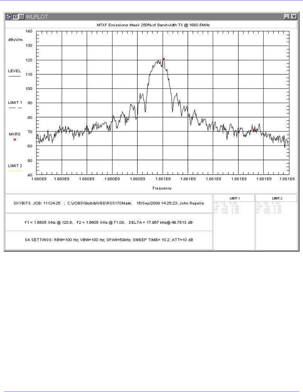
Figure 9: Spectrum Plot, High Channel @ +/-250% of BW .....................................................................19
Figure 10: GPS Band Emissions Low Channel, 1559 – 1605MHz Vertical Antenna Polarity.................26
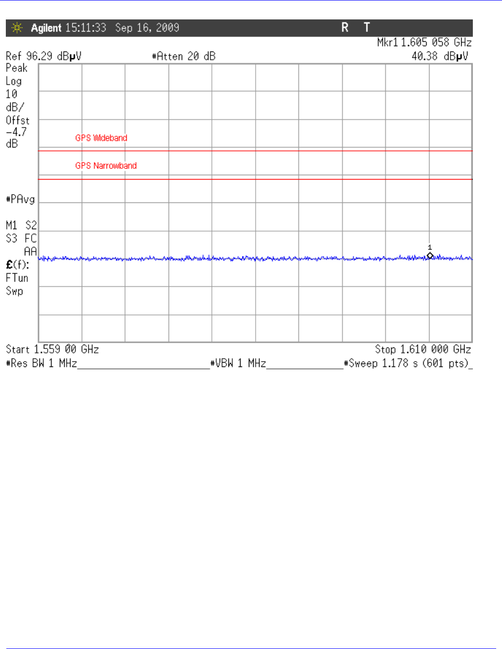
Figure 11: GPS Band Emissions Low Channel, 1605 – 1610MHz Vertical Antenna Polarity.................27
Figure 12: GPS Band Emissions Low Channel, 1559 – 1605MHz Horizontal Antenna Polarity ............28
Figure 13: GPS Band Emissions Low Channel, 1605 – 1610MHz Horizontal Antenna Polarity ............29
Figure 14: GPS Band Emissions Middle Channel, 1559 – 1605MHz, Vertical Antenna Polarity ...........30
Figure 15: GPS Band Emissions Middle Channel, 1605 – 1610MHz, Vertical Antenna Polarity ...........31
Figure 16: GPS Band Emissions Middle Channel, 1559 – 1605MHz, Horizontal Antenna Polarity .......32
Figure 17: GPS Band Emissions Middle Channel, 1605 – 1610MHz, Horizontal Antenna Polarity .......33
Figure 18: GPS Band Emission, Carrier Off, Mid Channel, 1559 – 1610MHz ........................................34
Figure 19: GPS Band Emissions High Channel, 1559 – 1605MHz Vertical Antenna Polarity................35
Figure 20: GPS Band Emissions High Channel, 1605 – 1610MHz Vertical Antenna Polarity................36
Figure 21: GPS Band Emissions High Channel, 1559 – 1605MHz Horizontal Antenna Polarity............37
Figure 22: GPS Band Emissions High Channel, 1605 – 1610MHz Horizontal Antenna Polarity............38

Skybitz Inc
MTXM
FCC/IC Test Report
November, 2009
WLL Report #11125-01 Rev. 3 - Page 1 of 40 - © 2009 Washington Laboratories, Ltd.
1 Introduction
1.1 Compliance Statement
The SkyBitz, Inc. MTXM L-Band Mobile Satellite Terminal complies with the limits for a Mobile
Earth Station under FCC Part 25 and Industry Canada RSS-170.
1.2 Test Scope
Tests for radiated and conducted emissions were performed. All measurements were performed
according to the 2003 version of ANSI C63.4. The measurement equipment conforms to ANSI C63.2
Specifications for Electromagnetic Noise and Field Strength Instrumentation.
1.3 Contract Information
Customer: SkyBitz, Inc.
22455 Davis Drive Suite 100
Sterling, Virginia 20164
Purchase Order Number: 0004510
Quotation Number: 65038
1.4 Test Dates
Testing was performed on the following date(s): 9/13/2009 through 9/25/2009
1.5 Test and Support Personnel
Washington Laboratories, LTD John P. Repella
Client Representative Dana Johnson

Skybitz Inc
MTXM
FCC/IC Test Report
November, 2009
WLL Report #11125-01 Rev. 3 - Page 2 of 40 - © 2009 Washington Laboratories, Ltd.
1.6 Abbreviations
A Ampere
ac alternating current
AM Amplitude Modulation
Amps Amperes
b/s bits per second
BW BandWidth
CE Conducted Emission
cm Centimeter
CW Continuous Wave
dB Decibel
dc direct current
EMI Electromagnetic Interference
EUT Equipment Under Test
FM Frequency Modulation
G giga - prefix for 109 multiplier
Hz Hertz
IF Intermediate Frequency
k kilo - prefix for 103 multiplier
LISN Line Impedance Stabilization Network
M Mega - prefix for 106 multiplier
m Meter
µ micro - prefix for 10-6 multiplier
NB Narrowband
QP Quasi-Peak
RE Radiated Emissions
RF Radio Frequency
rms root-mean-square
SN Serial Number
S/A Spectrum Analyzer
V Volt

Skybitz Inc
MTXM
FCC/IC Test Report
November, 2009
WLL Report #11125-01 Rev. 3 - Page 3 of 40 - © 2009 Washington Laboratories, Ltd.
2 Equipment Under Test
2.1 EUT Identification & Description
The SkyBitz, Inc. MTXM L-Band Mobile Terminal transmits and receives messages through the
SkyBitz network. Its integrated design includes a software-based radio, antennas, and lithium battery
pack in one package.
Table 1: Device Summary
ITEM DESCRIPTION
Manufacturer: SkyBitz, Inc.
FCC ID Number SAE-000MTXM
IC ID Number 5375A-000MTXM
EUT Name: Mobile Terminal
Model: MTXM
FCC Rule Parts: §25
IC Rule Parts RSS-170 Annex B
Frequency Range: TX: 1626.5-1660.5MHz
RX: 1525-1559MHz & 1575.42MHz
1626.5-1660.5MHz(authorized)
Maximum Output Power: 1.3 watts EIRP
Modulation: MSK
Necessary Bandwidth 4.248 kHz
Occupied Bandwidth (20dB): 4.3569kHz
Keying: Automatic
Type of Information: Data
Number of Channels: Variable- determined by satellite provider
Antenna Type Integral
Frequency Tolerance: 0.001% (FCC), +/-320 Hz (IC)
Emission Type(s): G1D
Emissions Designator 4K36G1D
Interface Cables: RS485 Interface
Power Source & Voltage: 6Vdc from batteries
Final RF Amp Voltage 4.9 VDC
Final RF Amp Current 275 mA
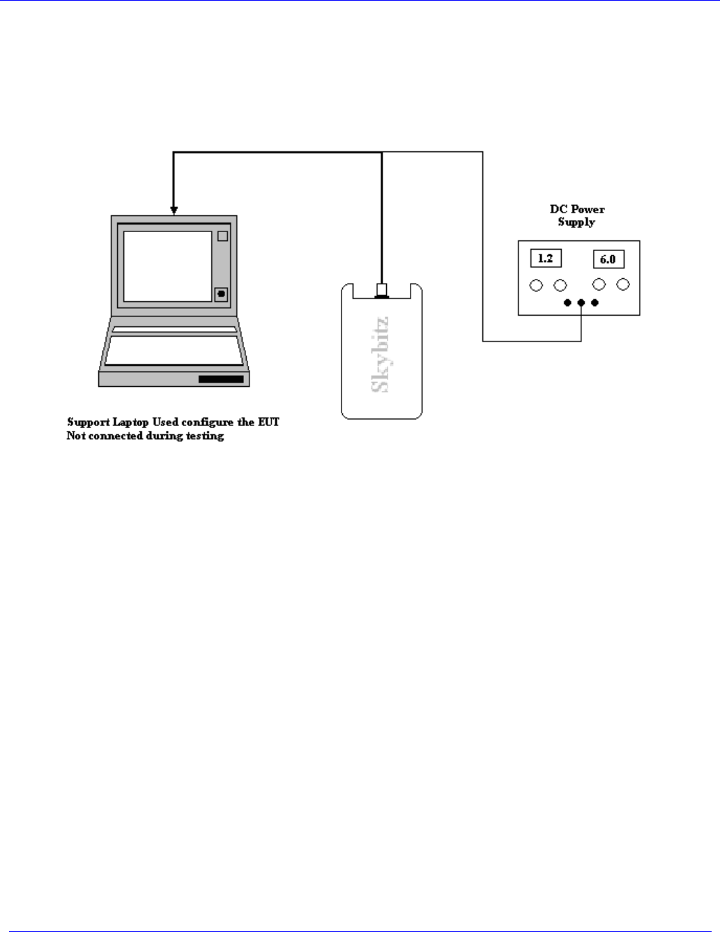
2.2 Test Configuration
The EUT was configured with a support laptop and an RS485 adapter. The laptop used SkyBitz
software, SkyPort, to configure the system for continuous transmit. A separate DC power supply was
used to provide a constant 6Vdc to the EUT so as not to drain the batteries.
The EUT firmware/software was set up to simulate normal transmission to a satellite
Skybitz Inc
MTXM
FCC/IC Test Report
November, 2009
WLL Report #11125-01 Rev. 3 - Page 4 of 40 - © 2009 Washington Laboratories, Ltd.
Figure 1: Test Setup Diagram
2.3 Testing Algorithm
The MTXF L-Band Mobile Terminal was configured by SkyBitz software on the support laptop to
continually transmit on the following channels:
♦ Low channel: 1626.505 MHz –limited testing ( Power, Bandwidth and Emission Masks)
♦ Center channel: 1643.5 MHz- full testing
♦ High channel: 1660.495 MHz- limited testing (Power, Bandwidth and Emission Masks)
Worst case emission levels are provided in the test results data.

Skybitz Inc
MTXM
FCC/IC Test Report
November, 2009
WLL Report #11125-01 Rev. 3 - Page 5 of 40 - © 2009 Washington Laboratories, Ltd.
2.4 Test Location
Testing was performed on an Open Area Test Site (OATS) of Washington Laboratories, Ltd, 7560
Lindbergh Drive, Gaithersburg, MD 20879.
Testing that was performed on an Open Area Test Site (OATS) of Washington Laboratories, Ltd,
7560 Lindbergh Drive, Gaithersburg, MD 20879. Site description and site attenuation data have been
placed on file with the FCC's Sampling and Measurements Branch at the FCC laboratory in
Columbia, MD. The Industry Canada OATS numbers are 3035A-1 and 3035A-2 for Washington
Laboratories, Ltd. Site 1 and Site 2, respectively. Washington Laboratories, Ltd. has been accepted by
the FCC and approved by the American Association for Laboratory Accreditation (A2LA) under
Certificate 2675.01 as an independent FCC test laboratory.
2.5 Measurements
2.5.1 References
ANSI C63.2 Specifications for Electromagnetic Noise and Field Strength Instrumentation
ANSI C63.4 American National Standard for Methods of Measurement of Radio-Noise Emissions from
Low-Voltage Electrical and Electronic Equipment in the Range of 9 kHz to 40 GHz
RSS170 Issue 1, Rev. 1 Satellite Mobile Earth Stations
47 CFR Part 25
2.6 Measurement Uncertainty
All results reported herein relate only to the equipment tested. For the purposes of the measurements
performed by Washington Laboratories, the measurement uncertainty is ±2.3 dB. This has been
calculated for a worst-case situation (radiated emissions measurements performed on an open area test
site).
The following measurement uncertainty calculation is provided:
Total Uncertainty = (A2 + B2 + C2)1/2/(n-1)
Where:
A = Antenna calibration uncertainty, in dB = 2 dB
B = Spectrum Analyzer uncertainty, in dB = 1 dB
C = Site uncertainty, in dB = 4 dB
n = number of factors in uncertainty calculation = 3
Thus, Total Uncertainty = 0.5 (22 + 12 + 42)1/2 = ±2.3 dB.

Skybitz Inc
MTXM
FCC/IC Test Report
November, 2009
WLL Report #11125-01 Rev. 3 - Page 6 of 40 - © 2009 Washington Laboratories, Ltd.
3 Test Equipment
Table 2 shows a list of the test equipment used for measurements along with the calibration information.
Table 2: Test Equipment List
Test
Name: Radiated Emissions Test Date: 09/24/2009
Asset # Manufacturer/Model Description Cal. Due
68 HP, 85650A Adapter, QP 07/10/2010
72 HP, 8568B Analyzer, Spectrum 07/10/2010
70 HP, 85685A Preselector, RF w/opt 8ZE 07/10/2010
382 Sunol, JB1 Antenna, Biconlog 01/27/2010
626 ARA, DRG-118/A Antenna, Horn 06/03/2011
667
MegaPhase, LLC
EM18-S1NK5-600
Test cable for OATS testing DC to 18 GHz SMA
male 04/23/2010
528 Agilent, E4446A Analyzer, Spectrum 09/04/2010
66 HP, 8449B Pre-Amplifier, RF. 1-26.5GHz 07/21/2010
640 MegaPhase, TM40-K1K5-36 1G-40GHz Right angle 09/29/2009
428 EMCO, 3109 Antenna, Bicon 3/6/2010
556 EMCO, 3146A Antenna, Log Periodic 8/15/2010
1 A.H., Systems, SAS-200/518 Antenna, LP, 1-18GHz 04/29/2010
4 ARA, DRG-118/A Antenna, DRG, 1-18GHz 02/06/2011
520 Megaphase, LLC TM40-K1K1-36 Cable, Coaxial - 36" Long - 40GHz 2.9mm 09/29/2009
628 Megaphase - F230-S1S1-226 DC- 18GHz SMA 246cm 07/15/2009
629 Megaphase - F230-S1S1-226 DC- 18GHz SMA 246cm 06/11/2010

Skybitz Inc
MTXM
FCC/IC Test Report
November, 2009
WLL Report #11125-01 Rev. 3 - Page 7 of 40 - © 2009 Washington Laboratories, Ltd.
4 Test Results
4.1 RF Power Output (FCC 25.204, RSS-170 Section 6.2)
FCC 25.204 specifies the limits for Satellite Earth Stations.
In bands shared coequally with terrestrial radio communication services, the equivalent isotropically
radiated power transmitted in any direction towards the horizon by an earth station operating in
frequency bands between 1 and 15 GHz, shall not exceed the following limits:
+40 dBW in any 4 KHz band for θ: 0°
+40+3 θ dBW in any 4 KHz band for θ <0°≤05°
Where, θ is the angle of elevation of the horizon viewed from the center of radiation of the
antenna of the earth station and measured in degrees as positive above the horizontal plane and
negative below it.
IC RSS-170 Section 6.2 and Annex B specify the following requirements:
The output power shall be measured when the transmitter is operating at the manufacturer’s rated
power and modulated with signals representative (i.e. typical) of those encountered in a real system
operation. This measurement shall be carried out before the other tests.
If the power is in bursts, the power shall be averaged over any 100 millisecond interval, or over the
burst interval if the burst is shorter than 100 milliseconds, during which its value is at its maximum.
Record the output power.
4.1.1 Power measurement test procedure – Signal Substitution Method
No direct connection to the antenna is available for making the power measurement as the antenna is
integrated with the unit.
To measure the EIRP the EUT was placed on motorized turntable for radiated testing on a 3-meter
open field test site. The emissions from the EUT were measured continuously at every azimuth by
rotating the turntable. Receiving antennas were mounted on an antenna mast to determine the height of
maximum emissions. The height of the antenna was varied between 1 and 4 meters. Cables were
varied in position to produce maximum emissions. Both the horizontal and vertical field components
of the EUT were measured.
The received level of the detected emission was recorded in the data sheet. The EUT is then replaced
with a transmit antenna and signal generator. Output power of the signal generator was increased until
the same received level was indicated on the spectrum analyzer for the emission under investigation.
Radiated power of the emission was then determined by adding the forward power supplied to the
substitution antenna with the gain of the substitution antenna and comparing the result to the limit.

Skybitz Inc
MTXM
FCC/IC Test Report
November, 2009
WLL Report #11125-01 Rev. 3 - Page 8 of 40 - © 2009 Washington Laboratories, Ltd.
As specified above, the limit is +40 dBW in any 4 kHz band. The analyzer used for testing was
limited to a 3 kHz measurement bandwidth. To adjust to the 4 kHz specification a BW correction of
+1.25 dB was added to the final reading. The following calculations were used for determining the
EIRP level:
Pout (dBW) = SL (dBm) + G (dBi) + -30(dB)
Where: SL is the substitution level in dBm
G is the substitution antenna gain in dBi
-30dB is the conversion factor for dBm to dBW
Table 3: RF Power Output
Frequency
(MHz)
Polarity
H/V
Azimuth
Degree
Ant.
Height
(m)
Spurious
Level
(dBm)
Sub.
Sig.
Gen.
Level
(dBm)
Sub.
Power
Level
(dBm)
Sub.
Ant.
Factor
(dB/m)
Sub.
Ant.
Gain
dBi
EIRP
Level
dBW/4kHz
Limit
(dBW/4kHz)
Margin
(dB)
1626.505 V 0.0 1.0 98.0 27.1 25.4 28.8 5.7 2.3 40.0 -37.7
1643.50 V 0.0 1.0 98.6 24.6 23.0 28.9 5.7 -0.1 40.0 -40.1
1660.495 V 0.0 1.0 98.7 21.5 19.6 29.0 5.7 -3.5 40.0 -43.5
1626.505 H 345.0 1.0 96.2 26.2 24.5 28.8 5.7 1.4 40.0 -38.6
1643.500 H 345.0 1.0 96.4 22.6 20.9 28.9 5.7 -2.2 40.0 -42.2
1660.495 H 345.0 1.0 96.9 22.5 20.6 29.0 5.7 -2.5 40.0 -42.5
Skybitz Inc
MTXM
FCC/IC Test Report
November, 2009
WLL Report #11125-01 Rev. 3 - Page 9 of 40 - © 2009 Washington Laboratories, Ltd.
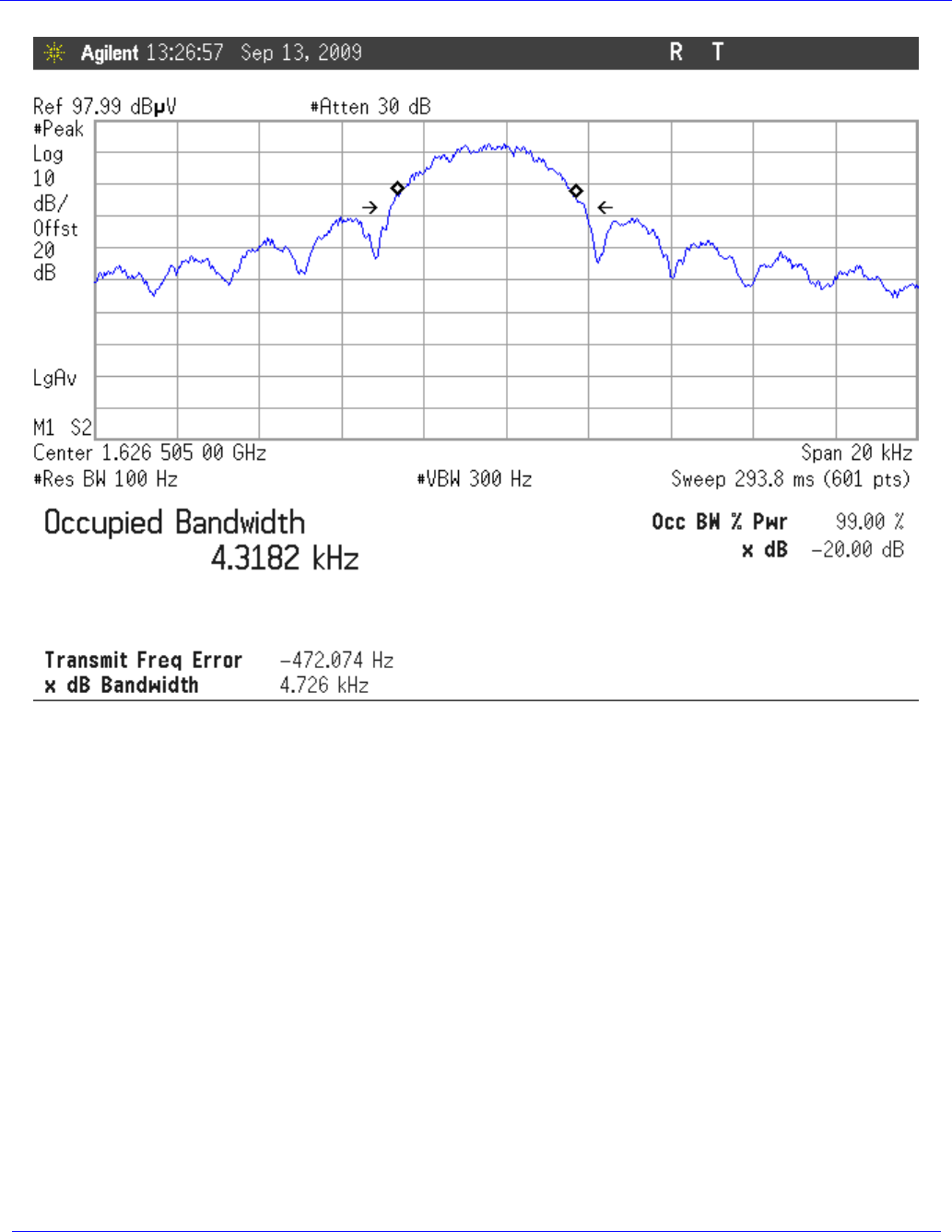
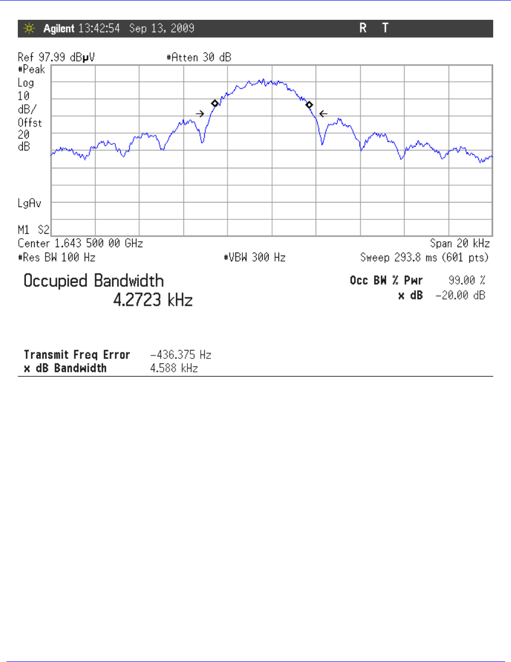
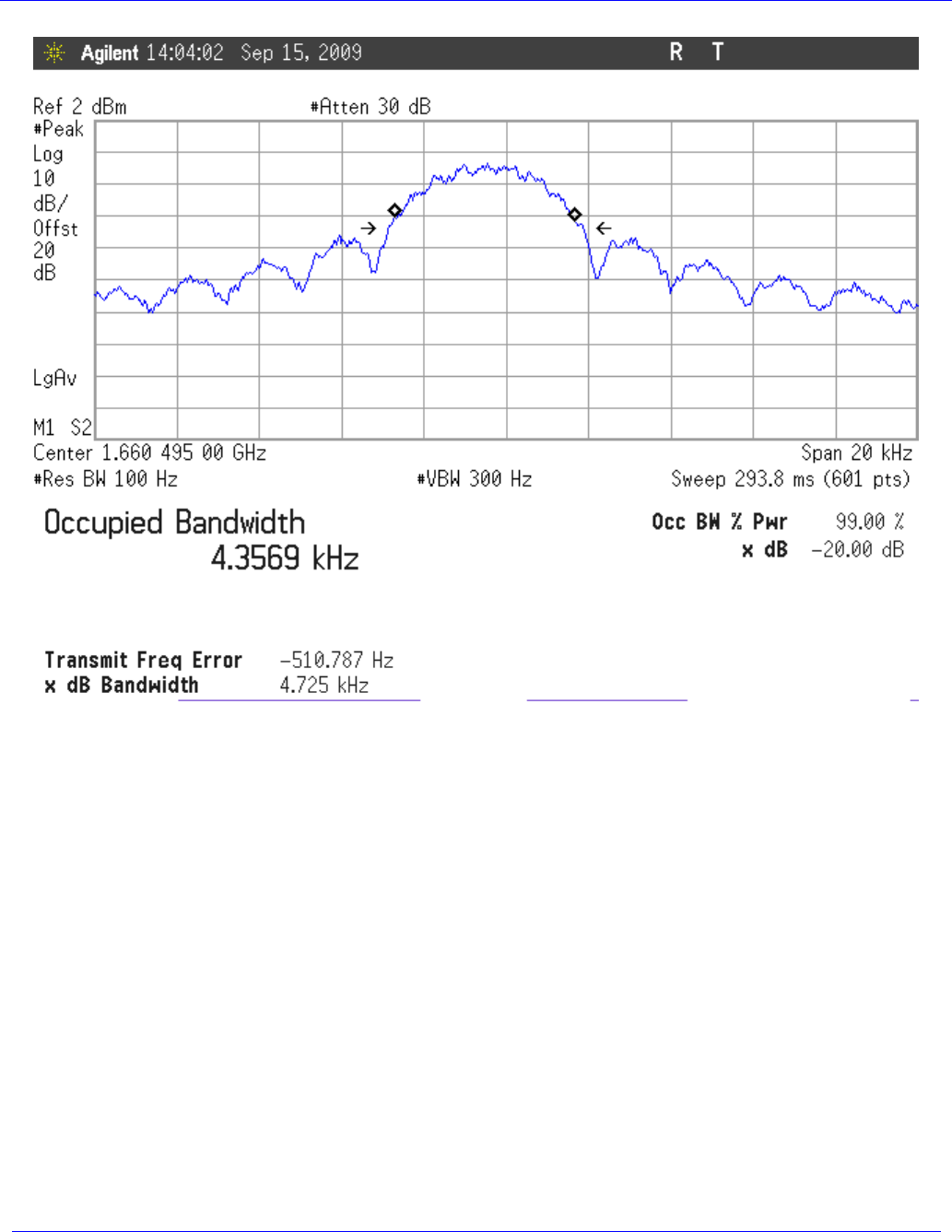
4.2 Occupied Bandwidth
The occupied bandwidth of the MTXF Mobile Terminal was measured. This measurement was
performed by coupling the output of the EUT via an antenna to the input of a spectrum analyzer. The
20dB occupied bandwidth was measured for the Low, High and Middle channels and the test results
are listed in the following table. Figure 2 thru Figure 4 show plots of the occupied bandwidth.
Table 4: Occupied Bandwidth Results
Frequency
(MHz)
Occupied Bandwidth
(kHz)
Standard
Reference
Low Channel: 1626.505 4.3182 kHz RSS-170
Middle Channel: 1643.5 4.2723 kHz FCC Part 25
High Channel: 1660.5 4.3569 kHz RSS-170
The necessary BW for a 2-ary MSK (Minimum Shift Keying) signal is calculated as follows:
Number of states = 2
Bit Rate R = 3.6 kbps
Factor K’ = 1.18 for a 2-ary MSK signal {NOTE: K’ = (1/Log2(number of States) + 0.18) =
(1/(Ln(2)/Ln(2) + 0.18) = 1 + 0.18 = 1.18} {also note that this is for unfiltered MSK, where any
filtering is sufficiently wide that it has no or little effect on the occupied BW}.
Necessary BW Bn = R X K’ for an MSK signal
Bn = 3.6 kbps X 1.18 = 4.248 kHz
MSK is considered phase modulation (“G”), we utilize a single channel (“1”), and we transmit data
(“D”). This is consistent with Part 2.201 Subpart C-Emissions.
Therefore the emission designator based on FCC part 2.202 is something like 4K25G1D. The actual
emission designator is based on the -26 dB or 99% occupied BW measurement.
Skybitz Inc
MTXM
FCC/IC Test Report
November, 2009
WLL Report #11125-01 Rev. 3 - Page 10 of 40 - © 2009 Washington Laboratories, Ltd.
Figure 2: Occupied Bandwidth, Low Channel, TX @ 1626.505MHz
Skybitz Inc
MTXM
FCC/IC Test Report
November, 2009
WLL Report #11125-01 Rev. 3 - Page 11 of 40 - © 2009 Washington Laboratories, Ltd.
Figure 3: Occupied Bandwidth, Mid Channel, TX @ 1643.5MHz
Skybitz Inc
MTXM
FCC/IC Test Report
November, 2009
WLL Report #11125-01 Rev. 3 - Page 12 of 40 - © 2009 Washington Laboratories, Ltd.
Figure 4: Occupied Bandwidth, High Channel, TX @ 1660.495MHz
Skybitz Inc
MTXM
FCC/IC Test Report
November, 2009
WLL Report #11125-01 Rev. 3 - Page 13 of 40 - © 2009 Washington Laboratories, Ltd.
4.3 Emission Limitations per FCC Part 25.202(f); RSS-170 Section 6.3 (Emission Masks)
Radiated spurious emissions must comply with the requirements of §25.202 (f) of FCC and Table B1
column (a) of RSS-170. The limits for the spurious emissions for RSS-170 and FCC Part 25 are as
follows:
FCC Part 25.202(f):
Radiated spurious emissions must comply with the requirements of §25.202(f). The limits for the
spurious emissions are as follows:
The mean power of emissions shall be attenuated below the mean output power of the transmitter in
accordance with the following schedule:
(1) In any 4 kHz band, the center frequency of which is removed from the assigned frequency by
more than 50 percent up to and including 100 percent of the authorized bandwidth: 25 dB;
(2) In any 4 kHz band, the center frequency of which is removed from the assigned frequency by
more than 100 percent up to and including 250 percent of the authorized bandwidth: 35 dB;
(3) In any 4 kHz band, the center frequency of which is removed from the assigned frequency by
more than 250 percent of the authorized bandwidth: An amount equal to 43 dB plus 10 times the
logarithm (to the base 10) of the transmitter power in watts.
RSS-170(B2):
The attenuation of the spectrum shall be in accordance with the schedule of column (a), or
alternatively of column (b) of Table B1, whichever is less stringent.
Table 5: Table B1 of RSS-170
Frequency Offset
Normalized to SR
(symbol rate)
(a) Minimum attenuation
relative to in-band spectral
density, (dB)
(b) Minimum attenuation relative
to transmitter output power (dB),
in any 4 kHz
+0.75 SR 0 0
+1.40 SR 20 30
+2.80 SR 40 50
+4.00 SR 55 or (37 + 10 Log10TP)
whichever is less stringent
65 or (47 + 10 Log10TP)
whichever is less stringent

Skybitz Inc
MTXM
FCC/IC Test Report
November, 2009
WLL Report #11125-01 Rev. 3 - Page 14 of 40 - © 2009 Washington Laboratories, Ltd.
4.3.1 Test Procedure
For the FCC Part 25 requirements the unit was set to transmit at 1643MHz and the emissions were
scanned to +/-250% of the authorized bandwidth and compared to the emission mask specified in
FCC Part 25.202(f). The authorized bandwidth used in the calculations for the limit was 7 kHz.
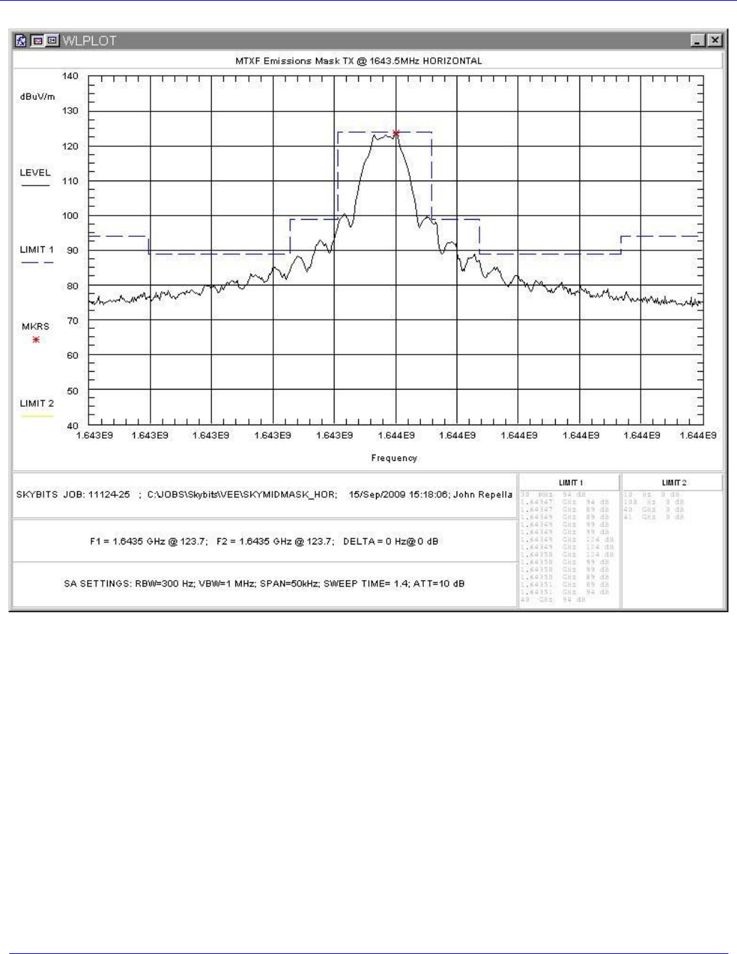
For complying with the RSS-170 emission mask, the unit was first set to transmit at the lowest
authorized frequency of 1626.505MHz. The emission mask of Table B1 column “a” was then entered
into the spreadsheet based on a baud rate of 3600. Discrete measurements of the channel power in a 4
kHz bandwidth were then measured and plotted against the limit curve. The unit was then set to the
highest authorized frequency of 1660.495MHz and the test was repeated.
Spectrum plots of the emissions as measured with a 100Hz RBW were also obtained at the low and
high channel settings.
4.3.2 Test Results
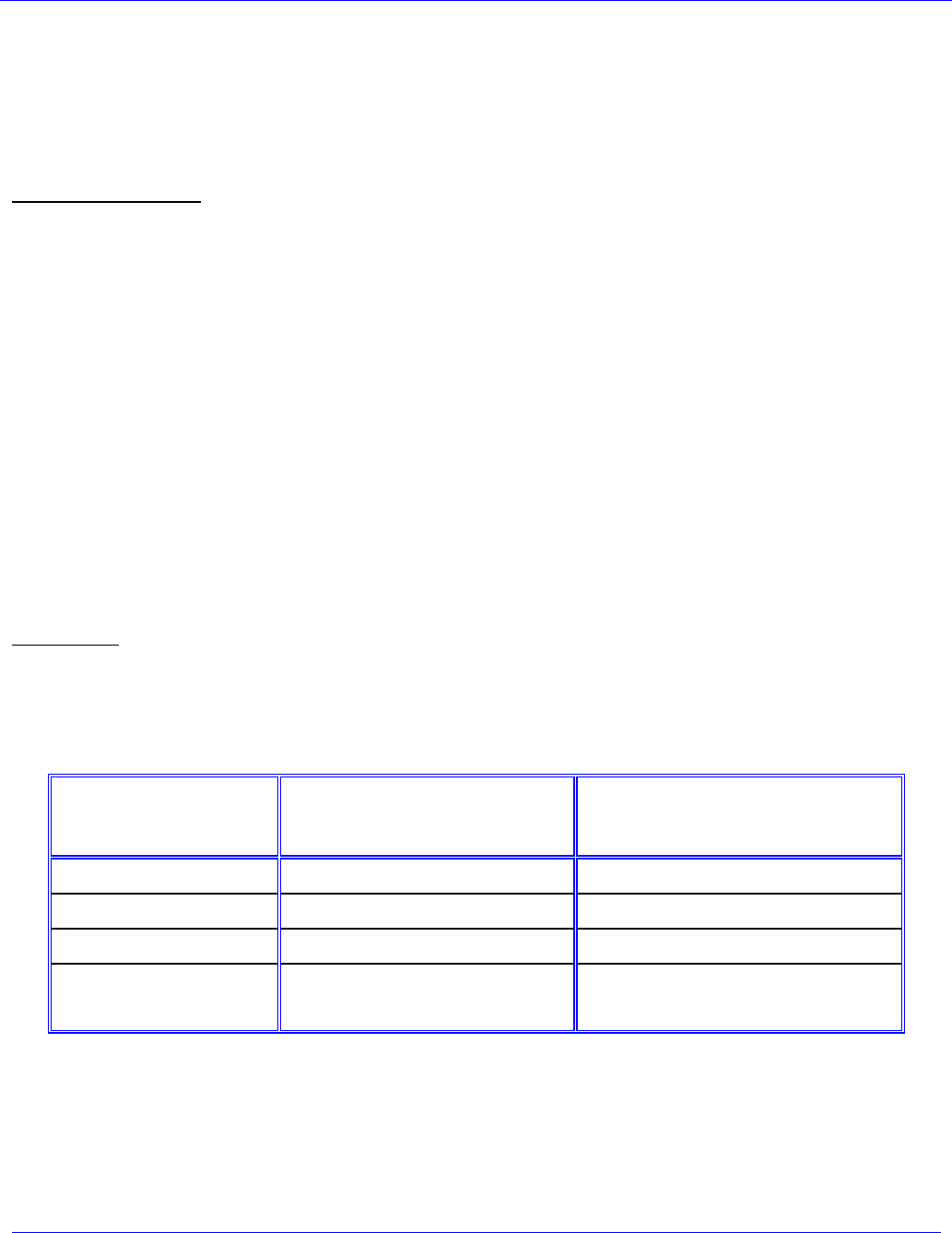
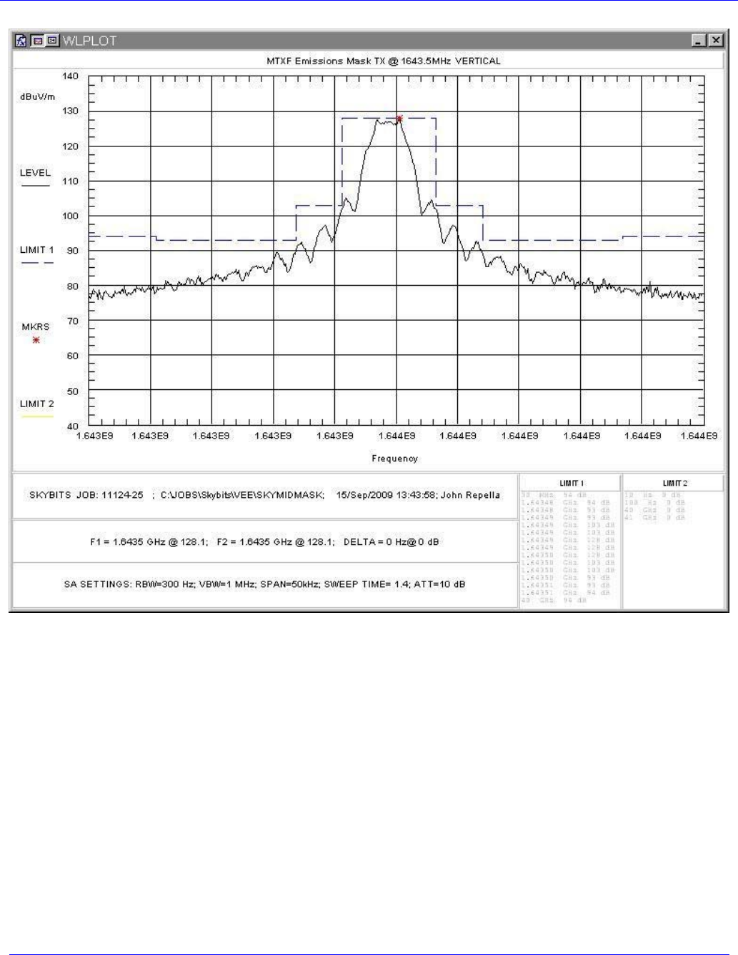
The EUT complies with the emissions mask requirements of FCC Part 25.202(f) and RSS-170 Annex
B. Figure 5 and Figure 6 contain the plots of the emissions mask for FCC Part 25.202(f). Figure 7,
Figure 8 and Figure 9 contain the plots of the emissions mask per RSS-170.
Skybitz Inc
MTXM
FCC/IC Test Report
November, 2009
WLL Report #11125-01 Rev. 3 - Page 15 of 40 - © 2009 Washington Laboratories, Ltd.
Figure 5: FCC Part 25.202(f) Emissions Mask, Vertical Polarity
Skybitz Inc
MTXM
FCC/IC Test Report
November, 2009
WLL Report #11125-01 Rev. 3 - Page 16 of 40 - © 2009 Washington Laboratories, Ltd.
Figure 6: FCC Part 25.202(f) Emissions Mask, Horizontal Polarity
Skybitz Inc
MTXM
FCC/IC Test Report
November, 2009
WLL Report #11125-01 Rev. 3 - Page 17 of 40 - © 2009 Washington Laboratories, Ltd.
Figure 7: Out-of-Band Emissions to Table B1
Skybitz Inc
MTXM
FCC/IC Test Report
November, 2009
WLL Report #11125-01 Rev. 3 - Page 18 of 40 - © 2009 Washington Laboratories, Ltd.
Figure 8: Spectrum Plot, Low Channel @ +/-250% of BW
Skybitz Inc
MTXM
FCC/IC Test Report
November, 2009
WLL Report #11125-01 Rev. 3 - Page 19 of 40 - © 2009 Washington Laboratories, Ltd.
Figure 9: Spectrum Plot, High Channel @ +/-250% of BW
Skybitz Inc
MTXM
FCC/IC Test Report
November, 2009
WLL Report #11125-01 Rev. 3 - Page 20 of 40 - © 2009 Washington Laboratories, Ltd.
4.4 Radiated Spurious Emissions: EIRP Data (FCC §25.202(f) and RSS-170,
Annex B3)
Radiated spurious emissions must comply with the requirements of §25.202 (f) of FCC. The limits for
the spurious emissions are as follows:
FCC Part 25.202(f):
Radiated spurious emissions must comply with the requirements of §25.202(f). The limits for the
spurious emissions are as follows:
The mean power of emissions shall be attenuated below the mean output power of the transmitter in
accordance with the following schedule:
(1) In any 4 kHz band, the center frequency of which is removed from the assigned frequency by more
than 50 percent up to and including 100 percent of the authorized bandwidth: 25 dB;
(2) In any 4 kHz band, the center frequency of which is removed from the assigned frequency by more
than 100 percent up to and including 250 percent of the authorized bandwidth: 35 dB;
(3) In any 4 kHz band, the center frequency of which is removed from the assigned frequency by more
than 250 percent of the authorized bandwidth: An amount equal to 43 dB plus 10 times the logarithm (to
the base 10) of the transmitter power in watts;
Based on the power measured, the limit for emissions removed from the center frequency by more than
250% of the authorized bandwidth will be:
Limit (dBm) = 34(dBm) – (43 + 10Log(2.51)) = -13dBm
RSS-170:
Spurious and harmonic emissions, excluding the frequency band of ±4 SR about the carrier frequency
(see Section 4.3) shall be attenuated below the transmitter output power TP in accordance with the
following Table from RSS-170 Annex B, when measured with a spectrum analyzer of 4 kHz
resolution bandwidth.
Frequency (MHz) Minimum Attenuation Relative to Tx Power in any 4 kHz
30-1559 83 dB or (65 + 10 Log10TP) dB whichever is less stringent
above 1559 55 dB or (37 + 10 Log10TP) dB whichever is less stringent
The limit for RSS-170 is therefore calculated as:
For 30-1559 MHz: 33dBm – (65+10Log(2W)) = -35dBm
Above 1559MHz: 33dBm – (37+10Log(2W)) = -7dBm

Skybitz Inc
MTXM
FCC/IC Test Report
November, 2009
WLL Report #11125-01 Rev. 3 - Page 21 of 40 - © 2009 Washington Laboratories, Ltd.
This section covers emissions detected at more than 250% removed from the authorized bandwidth.
4.4.1 Test Procedure
The EUT was placed on motorized turntable for radiated testing on a 3-meter open field test site. The
emissions from the EUT were measured continuously at every azimuth by rotating the turntable.
Receiving antennas were mounted on an antenna mast to determine the height of maximum emissions.
The height of the antenna was varied between 1 and 4 meters. The peripherals were placed on the table
in accordance with ANSI C63.4-2003. Cables were varied in position to produce maximum emissions.
Both the horizontal and vertical field components were measured.
Where emissions were detected, the EIRP levels were determined using the method of signal
substitution. The measurement bandwidth used was set to 3kHz. A 1.3dB correction was added to the
spectrum analyzer signal level for referencing to the specification bandwidth of 4kHz. The actual EIRP
level was calculated as follows.
EIRP (dBm) = Signal generator substitution level (dBm) + Antenna Gain (dBi)
4.4.2 Test Results
The frequency range of 30 MHz to 16.5 GHz was measured and the data presented below.
Table 6: Radiated Emissions
Frequency
(MHz)
Polarity Azimuth Ant.
Height
(m)
Spurious
Level
(dBuV)
Sub. Sig.
Gen.
Level
(dBm)
Sub.
Power
Level
(dBm)
Sub. Ant.
Factor
(dB)
Sub. Ant.
Gain
(dB)
EIRP
Level
(dBm)
Limit
(dBm)
Margin
(dB)
168.77 V 270.0 1.0 10.4 -64.8 -68.2 12.5 2.3 -65.9 -35.0 -30.9
238.317 V 0.0 1.4 4.7 -69.7 -73.0 15.7 2.1 -70.9 -35.0 -35.9
258.45 V 0.0 1.6 7.5 -64.3 -67.5 16.5 2.0 -65.5 -35.0 -30.5
350.34 V 0.0 2.2 3.5 -67.2 -70.6 16.6 4.5 -66.1 -35.0 -31.1
517.24 V 180.0 2.0 3.8 -62.5 -66.3 19.6 4.9 -61.4 -35.0 -26.4
168.77 H 315.0 1.4 8.6 -68.1 -71.4 12.5 2.3 -69.1 -35.0 -34.1
238.325 H 0.0 2.3 4.6 -68.3 -71.5 15.7 2.1 -69.4 -35.0 -34.4
258.45 H 0.0 2.5 4.3 -70.2 -73.4 16.5 2.0 -71.4 -35.0 -36.4
350.36 H 0.0 3.0 5.4 -72.1 -75.6 16.6 4.5 -71.1 -35.0 -36.1
517.24 H 225.0 3.0 3.6 -72.5 -76.3 19.6 4.9 -71.4 -35.0 -36.4

Skybitz Inc
MTXM
FCC/IC Test Report
November, 2009
WLL Report #11125-01 Rev. 3 - Page 22 of 40 - © 2009 Washington Laboratories, Ltd.
Frequency
(MHz)
Polarity Azimuth Ant.
Height
(m)
Spurious
Level
(dBuV)
Sub. Sig.
Gen.
Level
(dBm)
Sub.
Power
Level
(dBm)
Sub. Ant.
Factor
(dB)
Sub. Ant.
Gain
(dB)
EIRP
Level
(dBm)
Limit
(dBm)
Margin
(dB)
1357.037 V 0.0 1.0 22.80 -63.30 -64.7 27.1 5.8 -58.9 -13.0 -45.9
1621.522 V 0.0 1.0 48.80 -33.30 -34.9 28.7 5.7 -29.2 -13.0 -16.2
1623.278 V 0.0 1.0 42.70 -39.40 -41.0 28.7 5.7 -35.3 -13.0 -22.3
1627.628 V 0.0 1.0 52.10 -29.60 -31.2 28.8 5.7 -25.5 -13.0 -12.5
1630.469 V 0.0 1.0 58.50 -23.00 -24.6 28.8 5.7 -18.9 -13.0 -5.9
1635.808 V 0.0 1.0 52.30 -30.20 -31.8 28.8 5.7 -26.1 -13.0 -13.1
1641.602 V 0.0 1.0 44.30 -39.80 -41.4 28.8 5.7 -35.7 -13.0 -22.7
1644.405 V 0.0 1.0 45.70 -39.40 -41.0 28.9 5.7 -35.3 -13.0 -22.3
1645.552 V 0.0 1.0 45.70 -38.90 -40.5 28.9 5.7 -34.8 -13.0 -21.8
1647.103 V 0.0 1.0 49.00 -35.70 -37.3 28.9 5.7 -31.6 -13.0 -18.6
1649.414 V 0.0 1.0 44.00 -40.60 -42.2 28.9 5.7 -36.5 -13.0 -23.5
1650.189 V 0.0 1.0 54.00 -30.40 -32.0 28.9 5.7 -26.3 -13.0 -13.3
1655.530 V 0.0 1.0 61.50 -23.50 -25.1 28.9 5.7 -19.4 -13.0 -6.4
1658.371 V 0.0 1.0 56.60 -27.80 -29.4 28.9 5.7 -23.7 -13.0 -10.7
1664.491 V 0.0 1.0 50.90 -33.60 -35.3 29.0 5.7 -29.6 -13.0 -16.6
1928.509 V 0.0 1.0 42.60 -40.60 -42.5 30.5 5.5 -37.0 -13.0 -24.0
1928.951 V 0.0 1.0 43.10 -40.10 -42.0 30.5 5.5 -36.5 -13.0 -23.5
3287.000 V 0.0 1.0 57.90 -20.30 -22.6 35.4 5.2 -17.4 -13.0 -4.4
3857.901 V 0.0 1.0 46.40 -54.30 -56.9 36.1 5.9 -51.0 -13.0 -38.0
4143.853 V 0.0 1.0 35.80 -67.80 -70.5 36.5 6.1 -64.4 -13.0 -51.4
4930.500 V 0.0 1.0 69.30 -32.80 -36.3 36.7 7.4 -28.9 -13.0 -15.9
6072.804 V 0.0 1.0 43.70 -53.30 -57.5 39.5 6.4 -51.1 -13.0 -38.1
6574.000 V 0.0 1.0 62.90 -31.30 -36.5 39.2 7.4 -29.1 -13.0 -16.1
8217.500 V 0.0 1.0 60.50 -31.80 -38.1 43.1 5.5 -32.6 -13.0 -19.6
11504.50 V 0.0 1.0 45.90 -39.30 -47.3 47.6 3.8 -43.5 -13.0 -30.5
1357.037 H 0.0 1.0 28.4 -56.60 -58.0 27.1 5.8 -52.2 -13.0 -39.2
1621.522 H 0.0 1.0 47.7 -34.30 -35.9 28.7 5.7 -30.2 -13.0 -17.2
1623.278 H 0.0 1.0 43.5 -38.00 -39.6 28.7 5.7 -33.9 -13.0 -20.9
1627.628 H 0.0 1.0 52.7 -28.40 -30.0 28.8 5.7 -24.3 -13.0 -11.3
1630.469 H 0.0 1.0 57.7 -23.60 -25.2 28.8 5.7 -19.5 -13.0 -6.5
1635.808 H 0.0 1.0 50 -32.50 -34.1 28.8 5.7 -28.4 -13.0 -15.4
1641.602 H 0.0 1.0 41.3 -42.40 -44.0 28.8 5.7 -38.3 -13.0 -25.3
1644.405 H 0.0 1.0 41.9 -42.10 -43.7 28.9 5.7 -38.0 -13.0 -25.0
1645.552 H 0.0 1.0 40.6 -43.40 -45.0 28.9 5.7 -39.3 -13.0 -26.3
1647.103 H 0.0 1.0 41.3 -42.20 -43.8 28.9 5.7 -38.1 -13.0 -25.1
1649.414 H 0.0 1.0 38.6 -45.90 -47.5 28.9 5.7 -41.8 -13.0 -28.8
1650.189 H 0.0 1.0 46.7 -38.00 -39.6 28.9 5.7 -33.9 -13.0 -20.9
1655.530 H 0.0 1.0 50.4 -34.30 -35.9 28.9 5.7 -30.2 -13.0 -17.2
1658.371 H 0.0 1.0 44.9 -39.70 -41.3 28.9 5.7 -35.6 -13.0 -22.6
1664.491 H 0.0 1.0 38.7 -46.20 -47.9 29.0 5.7 -42.2 -13.0 -29.2
1928.509 H 0.0 1.0 46.8 -36.30 -38.2 30.5 5.5 -32.7 -13.0 -19.7
1928.951 H 0.0 1.0 53.3 -24.00 -25.9 30.5 5.5 -20.4 -13.0 -7.4
3287.000 H 315.0 1.0 52.9 -38.10 -40.4 35.4 5.2 -35.2 -13.0 -22.2
3857.901 H 0.0 1.0 27.3 -73.60 -76.2 36.1 5.9 -70.3 -13.0 -57.3
4143.853 H 0.0 1.0 67.9 -33.60 -36.3 36.5 6.1 -30.2 -13.0 -17.2
4930.500 H 315.0 1.0 42 -56.60 -60.1 36.7 7.4 -52.7 -13.0 -39.7
Skybitz Inc
MTXM
FCC/IC Test Report
November, 2009
WLL Report #11125-01 Rev. 3 - Page 23 of 40 - © 2009 Washington Laboratories, Ltd.
Frequency
(MHz)
Polarity Azimuth Ant.
Height
(m)
Spurious
Level
(dBuV)
Sub. Sig.
Gen.
Level
(dBm)
Sub.
Power
Level
(dBm)
Sub. Ant.
Factor
(dB)
Sub. Ant.
Gain
(dB)
EIRP
Level
(dBm)
Limit
(dBm)
Margin
(dB)
6072.804 H 0.0 1.0 67.7 -28.10 -32.3 39.5 6.4 -25.9 -13.0 -12.9
6574.000 H 315.0 1.0 61.3 -30.60 -35.8 39.2 7.4 -28.4 -13.0 -15.4
8217.500 H 315.0 1.0 28.9 -62.10 -68.4 43.1 5.5 -62.9 -13.0 -49.9
11504.50 H 315.0 1.0 39.1 -44.10 -52.1 47.6 3.8 -48.3 -13.0 -35.3
13148.00 H 315.0 1.0 45.3 -27.10 -34.6 48.1 4.5 -30.1 -13.0 -17.1
4.5 Receiver Spurious Emissions, RSS-170 Section 9.0
Spurious emissions related to the receiver were measured in accordance with RSS-170 Section 9.0.
Testing was performed at 3m test distance on an OATS. The emission scan was performed from
30MHz up to 5577MHz (3 times the highest LO).
Frequency
(MHz) Polarity
H/V Azimuth
(Degree) Ant.
Height (m) SA Level
(dBuV)
Corr
Factors
(dB)
Corr.
Level
(uV/m)
Limit
(uV/m) Margin
(dB)
41.06 V 180.00 1.00 7.80 14.3 12.7 100.0 -17.9
48.84 V 180.00 1.00 14.70 9.5 16.2 100.0 -15.8
111.09 V 0.00 1.00 14.30 13.6 24.7 150.0 -15.7
138.74 V 0.00 1.00 3.60 13.8 7.4 150.0 -26.1
228.87 V 0.00 1.00 5.40 12.4 7.8 200.0 -28.2
400.51 V 0.00 1.00 3.00 17.8 11.0 200.0 -25.2
569.24 V 0.00 1.00 6.20 20.3 21.1 200.0 -19.5
773.89 V 0.00 1.00 7.70 22.8 33.7 200.0 -15.5
928.92 V 0.00 1.00 6.00 26.0 39.6 200.0 -14.1
1647.24 V 180.00 1.00 38.20 -8.1 31.9 500.0 -23.9
1859.00 V 0.00 1.00 38.40 -6.5 39.3 500.0 -22.1
5577.00 V 0.00 1.00 32.60 0.6 45.5 500.0 -20.8
41.06 H 0.00 0.00 0.00 14.3 5.2 100.0 -25.7
48.84 H 180.00 3.00 3.80 9.5 4.6 100.0 -26.7
53.31 H 0.00 3.00 4.90 8.1 4.5 100.0 -27.0
111.09 H 0.00 3.00 7.80 13.6 11.7 150.0 -22.2
138.74 H 0.00 3.00 2.20 13.8 6.3 150.0 -27.5
228.87 H 0.00 3.00 5.70 12.4 8.1 200.0 -27.9
569.24 H 0.00 3.50 4.20 20.3 16.7 200.0 -21.5
773.89 H 0.00 3.50 3.90 22.8 21.7 200.0 -19.3
928.92 H 0.00 3.50 3.30 26.0 29.0 200.0 -16.8
1647.24 H 180.00 2.75 37.90 -8.1 30.8 500.0 -24.2
1859.00 H 0.00 3.00 36.80 -6.5 32.7 500.0 -23.7
5577.00 H 0.00 3.00 33.20 0.6 48.7 500.0 -20.2

Skybitz Inc
MTXM
FCC/IC Test Report
November, 2009
WLL Report #11125-01 Rev. 3 - Page 24 of 40 - © 2009 Washington Laboratories, Ltd.
4.6 Spurious Emissions per FCC §25.216
FCC Part 25 limits the emissions from mobile earth stations for the protection of aeronautical radio
navigation-satellite service. The EIRP density of spurious emissions which fall within the frequency
range of 1559M to 1610MHz were measured in accordance with §25.216.
In accordance with §25.216(c) the EIRP density of emissions from mobile earth stations operating
between 1610MHz and 1660.5MHz shall not exceed -70dBW/MHz, averaged over any 2ms active
transmission interval, in the band 1559M – 1605MHz. The EIRP of discrete emissions of less than 700
Hz bandwidth from such stations shall not exceed -80 dBW, averaged over any 2ms active transmission
interval, in the 1559M – 1605MHz band.
In accordance with §25.216(h) mobile earth stations manufactured more than six months after Federal
Register publication of the rule changes adopted in FCC 03-283 with assigned uplink frequencies in the
1626.5-1660.5 MHz band shall suppress the power density of emissions in the 1605-1610 MHz band-
segment to an extent determined by linear interpolation from -70 dBW/MHz at 1605 MHz to -46
dBW/MHz at 1610 MHz, averaged over any 2 millisecond active transmission interval. The e.i.r.p of
discrete emissions of less than 700 Hz bandwidth from such stations shall not exceed a level determined
by linear interpolation from -80 dBW at 1605 MHz to -56 dBW at 1610 MHz, averaged over any 2
millisecond active transmission interval.
In accordance with §25.216(i) the peak e.i.r.p density of carrier-off state emissions from mobile earth
stations manufactured more than six months after Federal Register publication of the rule changes
adopted in FCC 03–283 with assigned uplink frequencies between 1 and 3 GHz shall not exceed -80
dBW/MHz in the 1559– 1610 MHz band averaged over any 2 millisecond active transmission interval.
4.6.1 Test Procedure
The output of the EUT was connected to the input of measurement receiver with a RMS detector and the
capability of performing the measurements as specified in §25.216 (h). The following was used to
calculate the limit and the corrected emissions levels for obtaining the plots shown in Figure 10 through
Figure 22.
For emissions from 1559M – 1605MHz:
Limit = -70dBW/MHz = -40dBm/MHz
For discrete emissions with bandwidths less than 700Hz from 1559M – 1605MHz
Limit = -80dBW = -50dBm
For emissions from 1605M – 1610MHz:
Limit = -70dBW/MHz (-40dBm/MHz) to -46dBW/MHz (-16dBm/MHz)
For discrete emissions with bandwidths less than 700Hz from 1605M – 1610MHz
Limit = -80dBW/MHz (-50dBm/MHz) to -56dBW/MHz (-26dBm/MHz)

Skybitz Inc
MTXM
FCC/IC Test Report
November, 2009
WLL Report #11125-01 Rev. 3 - Page 25 of 40 - © 2009 Washington Laboratories, Ltd.
For emissions in the Carrier –Off State from 1559M – 1610MHz
Limit = -80dBW/MHz (-50dBm/MHz)
The receiver emissions levels were adjusted for correction factors as follows:
Emission Level = RXL + ATT+CBL+ANT
Where: RXL = Raw received level
ATT = Attenuator = 20dB
CBL=Cable loss=1.0
ANT= Tri-Band Antenna Gain=2.85dBi (5dBiC)
These correction factors were entered into the receiver as an offset so the obtained plots would display
corrected data for comparison to the limit.
Skybitz Inc
MTXM
FCC/IC Test Report
November, 2009
WLL Report #11125-01 Rev. 3 - Page 26 of 40 - © 2009 Washington Laboratories, Ltd.
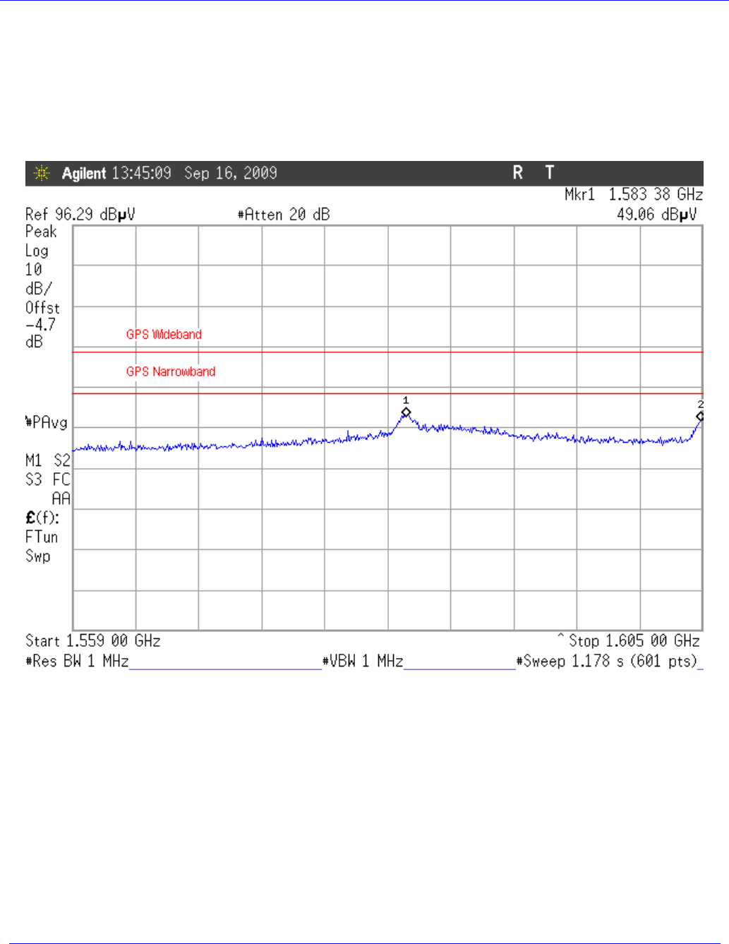
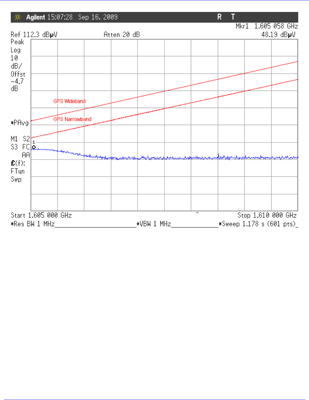
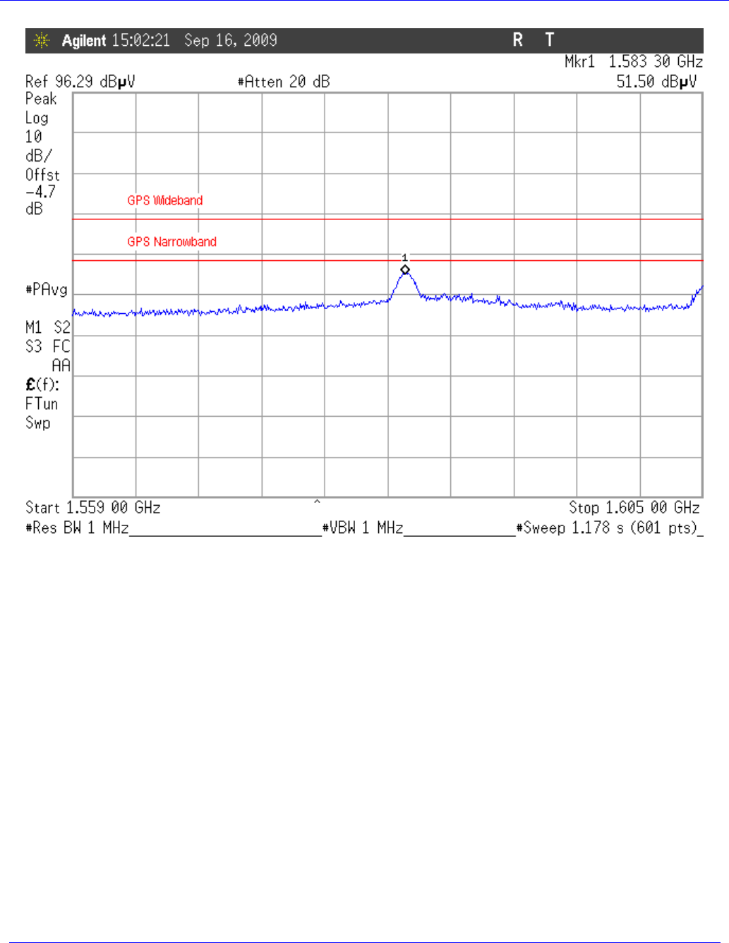
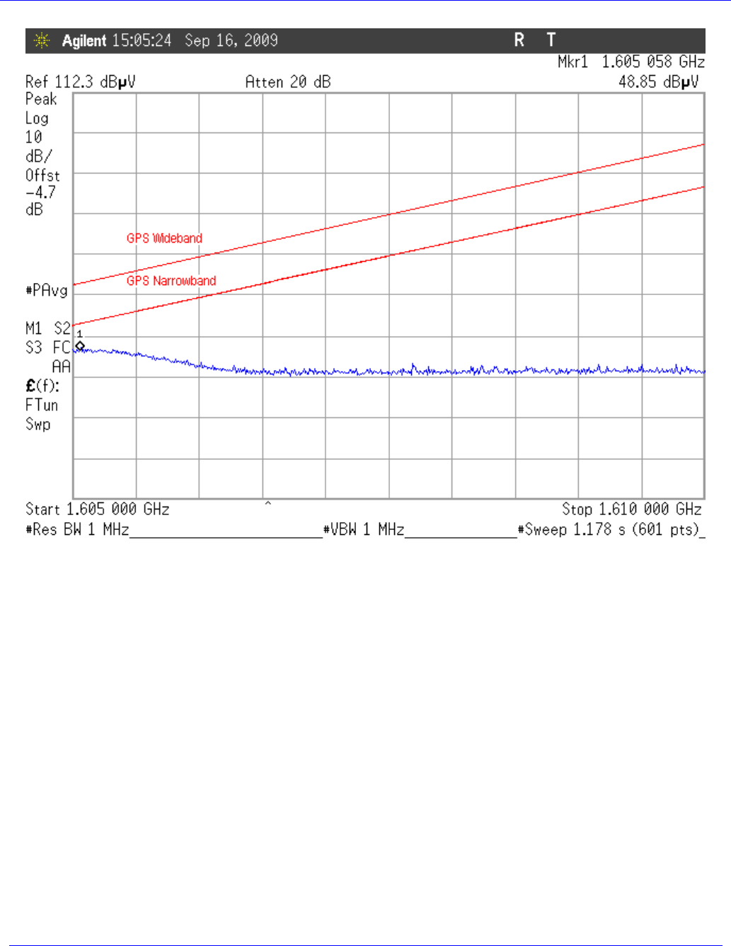
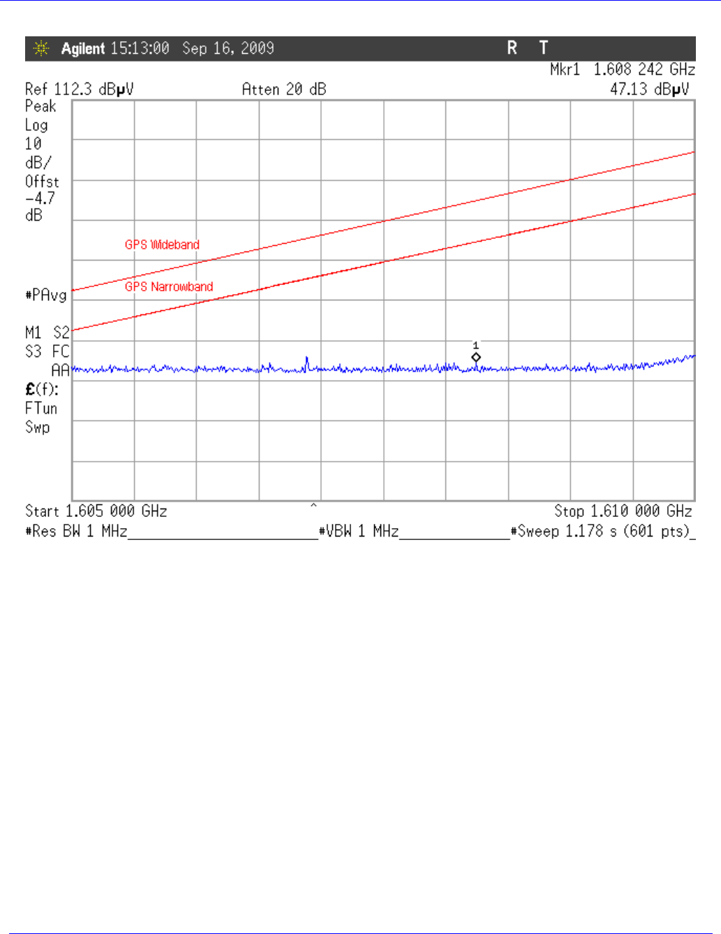
4.6.2 Test Results
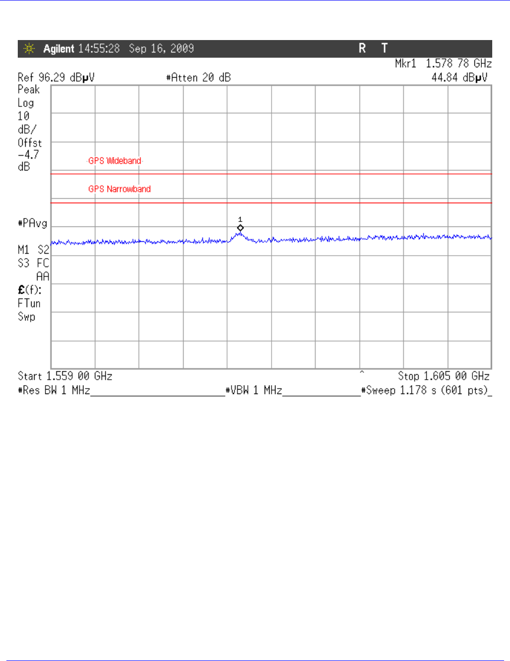
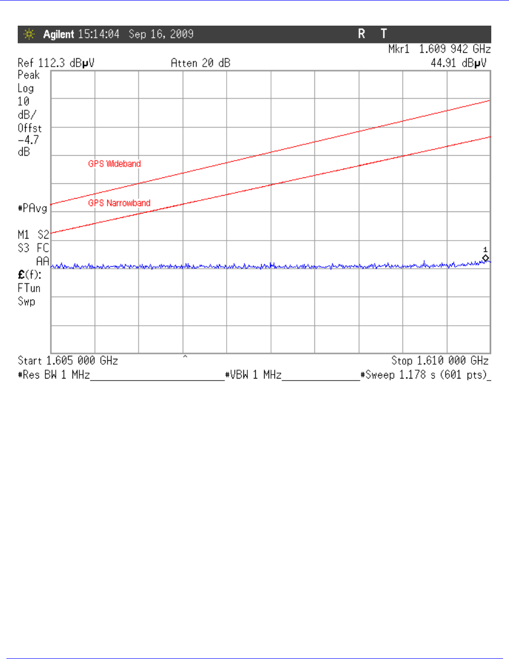
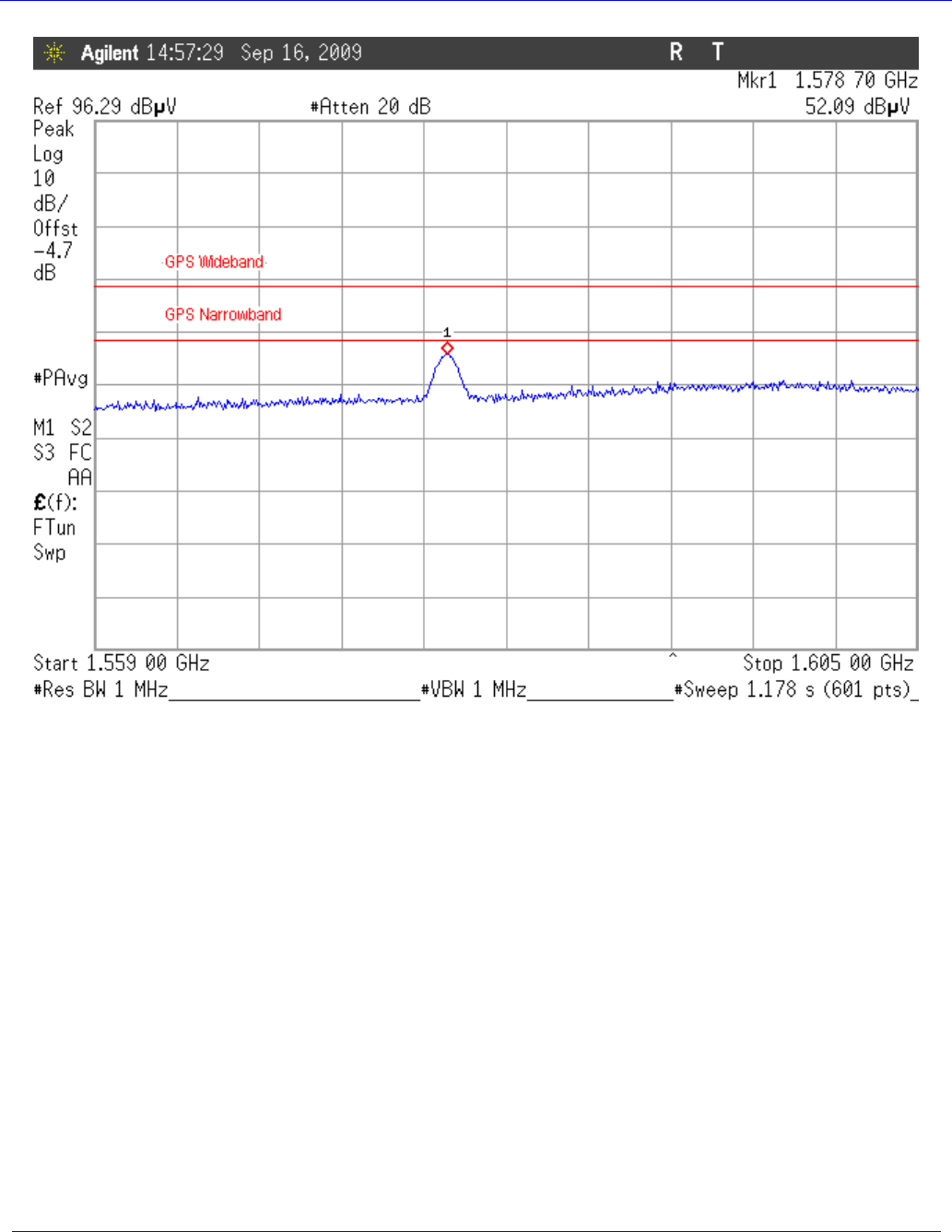
The following plot shows the maximum emissions detected with the band of 1559M – 1610MHz in both
a standby and operating mode and vertical and horizontal antenna polarity.
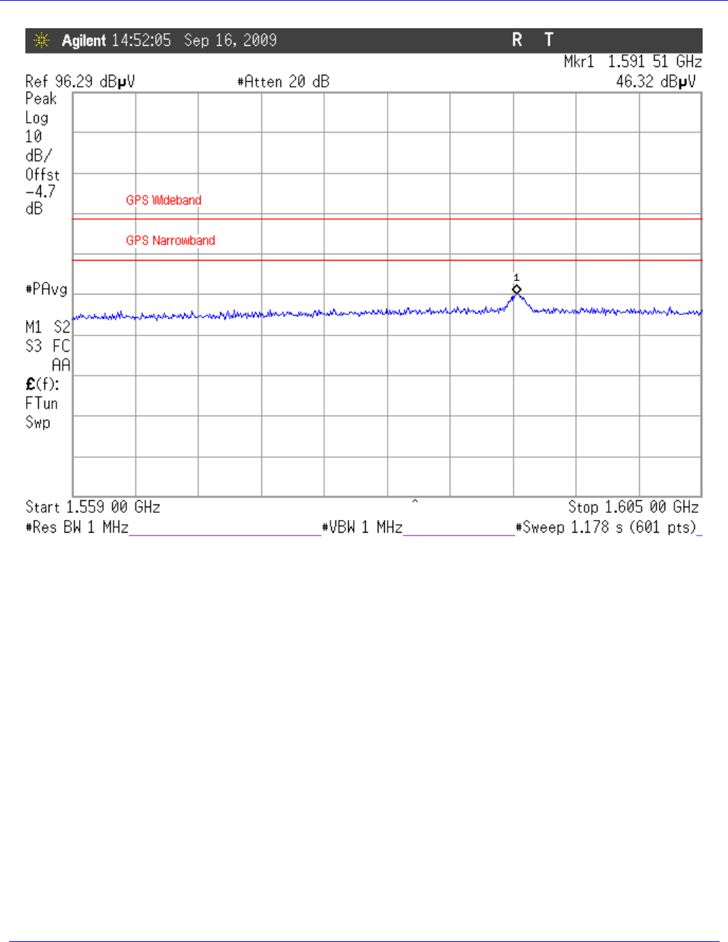
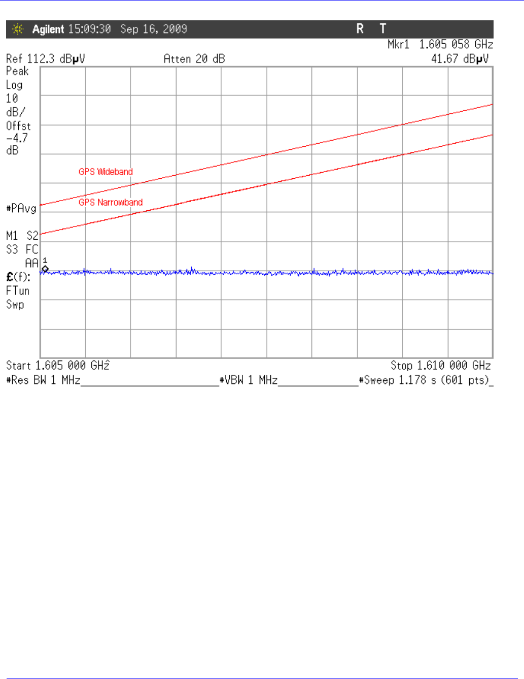
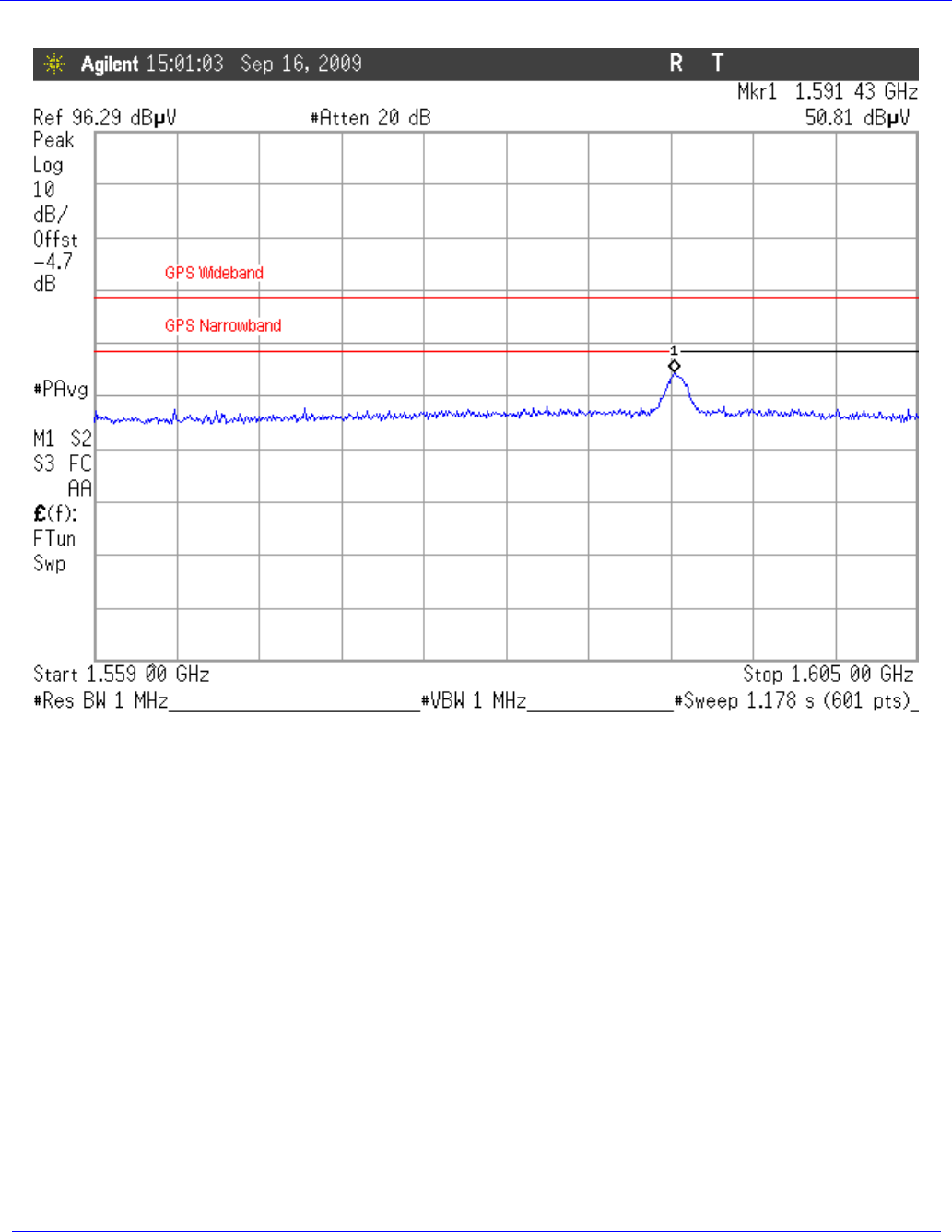
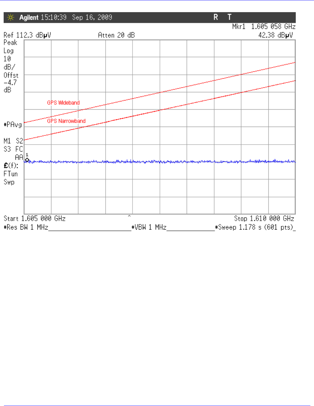
Figure 10: GPS Band Emissions Low Channel, 1559 – 1605MHz Vertical Antenna Polarity
Skybitz Inc
MTXM
FCC/IC Test Report
November, 2009
WLL Report #11125-01 Rev. 3 - Page 27 of 40 - © 2009 Washington Laboratories, Ltd.
Figure 11: GPS Band Emissions Low Channel, 1605 – 1610MHz Vertical Antenna Polarity
Skybitz Inc
MTXM
FCC/IC Test Report
November, 2009
WLL Report #11125-01 Rev. 3 - Page 28 of 40 - © 2009 Washington Laboratories, Ltd.
Figure 12: GPS Band Emissions Low Channel, 1559 – 1605MHz Horizontal Antenna Polarity
Skybitz Inc
MTXM
FCC/IC Test Report
November, 2009
WLL Report #11125-01 Rev. 3 - Page 29 of 40 - © 2009 Washington Laboratories, Ltd.
Figure 13: GPS Band Emissions Low Channel, 1605 – 1610MHz Horizontal Antenna Polarity
Skybitz Inc
MTXM
FCC/IC Test Report
November, 2009
WLL Report #11125-01 Rev. 3 - Page 30 of 40 - © 2009 Washington Laboratories, Ltd.
Figure 14: GPS Band Emissions Middle Channel, 1559 – 1605MHz, Vertical Antenna Polarity
Skybitz Inc
MTXM
FCC/IC Test Report
November, 2009
WLL Report #11125-01 Rev. 3 - Page 31 of 40 - © 2009 Washington Laboratories, Ltd.
Figure 15: GPS Band Emissions Middle Channel, 1605 – 1610MHz, Vertical Antenna Polarity
Skybitz Inc
MTXM
FCC/IC Test Report
November, 2009
WLL Report #11125-01 Rev. 3 - Page 32 of 40 - © 2009 Washington Laboratories, Ltd.
Figure 16: GPS Band Emissions Middle Channel, 1559 – 1605MHz, Horizontal Antenna Polarity
Skybitz Inc
MTXM
FCC/IC Test Report
November, 2009
WLL Report #11125-01 Rev. 3 - Page 33 of 40 - © 2009 Washington Laboratories, Ltd.
Figure 17: GPS Band Emissions Middle Channel, 1605 – 1610MHz, Horizontal Antenna Polarity
Skybitz Inc
MTXM
FCC/IC Test Report
November, 2009
WLL Report #11125-01 Rev. 3 - Page 34 of 40 - © 2009 Washington Laboratories, Ltd.
Figure 18: GPS Band Emission, Carrier Off, Mid Channel, 1559 – 1610MHz
Skybitz Inc
MTXM
FCC/IC Test Report
November, 2009
WLL Report #11125-01 Rev. 3 - Page 35 of 40 - © 2009 Washington Laboratories, Ltd.
Figure 19: GPS Band Emissions High Channel, 1559 – 1605MHz Vertical Antenna Polarity
Skybitz Inc
MTXM
FCC/IC Test Report
November, 2009
WLL Report #11125-01 Rev. 3 - Page 36 of 40 - © 2009 Washington Laboratories, Ltd.
Figure 20: GPS Band Emissions High Channel, 1605 – 1610MHz Vertical Antenna Polarity
Skybitz Inc
MTXM
FCC/IC Test Report
November, 2009
WLL Report #11125-01 Rev. 3 - Page 37 of 40 - © 2009 Washington Laboratories, Ltd.
Figure 21: GPS Band Emissions High Channel, 1559 – 1605MHz Horizontal Antenna Polarity
Skybitz Inc
MTXM
FCC/IC Test Report
November, 2009
WLL Report #11125-01 Rev. 3 - Page 38 of 40 - © 2009 Washington Laboratories, Ltd.
Figure 22: GPS Band Emissions High Channel, 1605 – 1610MHz Horizontal Antenna Polarity

Skybitz Inc
MTXM
FCC/IC Test Report
November, 2009
WLL Report #11125-01 Rev. 3 - Page 39 of 40 - © 2009 Washington Laboratories, Ltd.
4.7 Frequency Stability: (FCC Part §2.1055)
Frequency as a function of temperature and voltage variation shall be maintained within the FCC-
prescribed tolerances. Per §25.202(d) the frequency tolerance shall be maintained within 0.001% of the
reference frequency.
4.7.1 Test Procedure
The temperature stability was measured with the unit in an environmental chamber used to vary the
temperature of the sample. The sample was held at each temperature step to allow the temperature of the
sample to stabilize.
The frequency stability of the transmitter was examined at the voltage extremes and for the temperature
range of -30°C to +50°C. The carrier frequency was measured while the EUT was in the temperature
chamber. The reference frequency of the EUT was measured at the ambient room temperature with the
frequency counter.
The frequency stabilities can be maintained to a lesser temperature range provided that the transmitter is
automatically inhibited from operating outside the lesser temperature range.
The RF carrier frequency shall not depart from the reference frequency (reference frequency is the
frequency at 20ºC and rated supply voltage) in excess of .001%.
The EUT is powered by a 6 VDC voltage supplied via an external DC power supply.
4.7.2 Test Results
The EUT complies with the temperature stability requirements of FCC §25.202 and RSS-170. Test
results are given in Table 7.
Skybitz Inc
MTXM
FCC/IC Test Report
November, 2009
WLL Report #11125-01 Rev. 3 - Page 40 of 40 - © 2009 Washington Laboratories, Ltd.
Table 7: Frequency Stability Test Data
Temperature
(Centigrade) Frequency
(MHz) Difference
(Hz) Deviation
(%) Difference +/- 320Hz
RSS-170 Limit
Ambient 1643.499989 0.0 0
-30 1643.499950 -39.0 0.000002 Pass
-20 1643.4999210 -68.0 0.000004 Pass
-10 1643.4999110 -78.0 0.000005 Pass
0 1643.4999030 -86.0 0.000005 Pass
10 1643.4999070 -82.0 0.000005 Pass
20 1643.4999210 -68.0 0.000004 Pass
30 1643.4998170 -172.0 0.000010 Pass
40 1643.4998870 -102.0 0.000006 Pass
50 1643.4999040 -85.0 0.000005 Pass
Voltage (Volts) Frequency
(MHz) Difference
(Hz) Deviation
(%) Voltage (Volts)
At rated 1643.499989 0 0.0 6.2
At 85% 1643.4999040 -17.0 0.000001 5.3
At 115% 1643.4999210 104.0 0.000006 7.1
The EUT cuts off below 5.2 VDC.