Transact Campus VR4101X008 Vending Card Reader User Manual VR4100 InstallGuide
Blackboard Inc. Vending Card Reader VR4100 InstallGuide
UserManual.wiki
>
Transact Campus
>
VR4101X008 User Manual
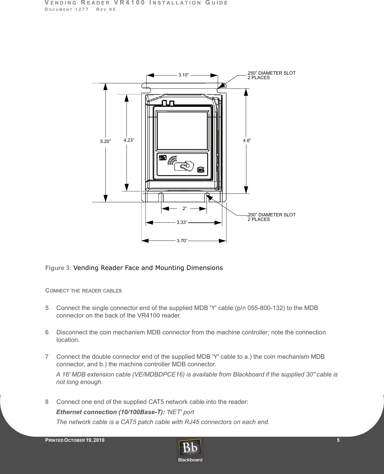
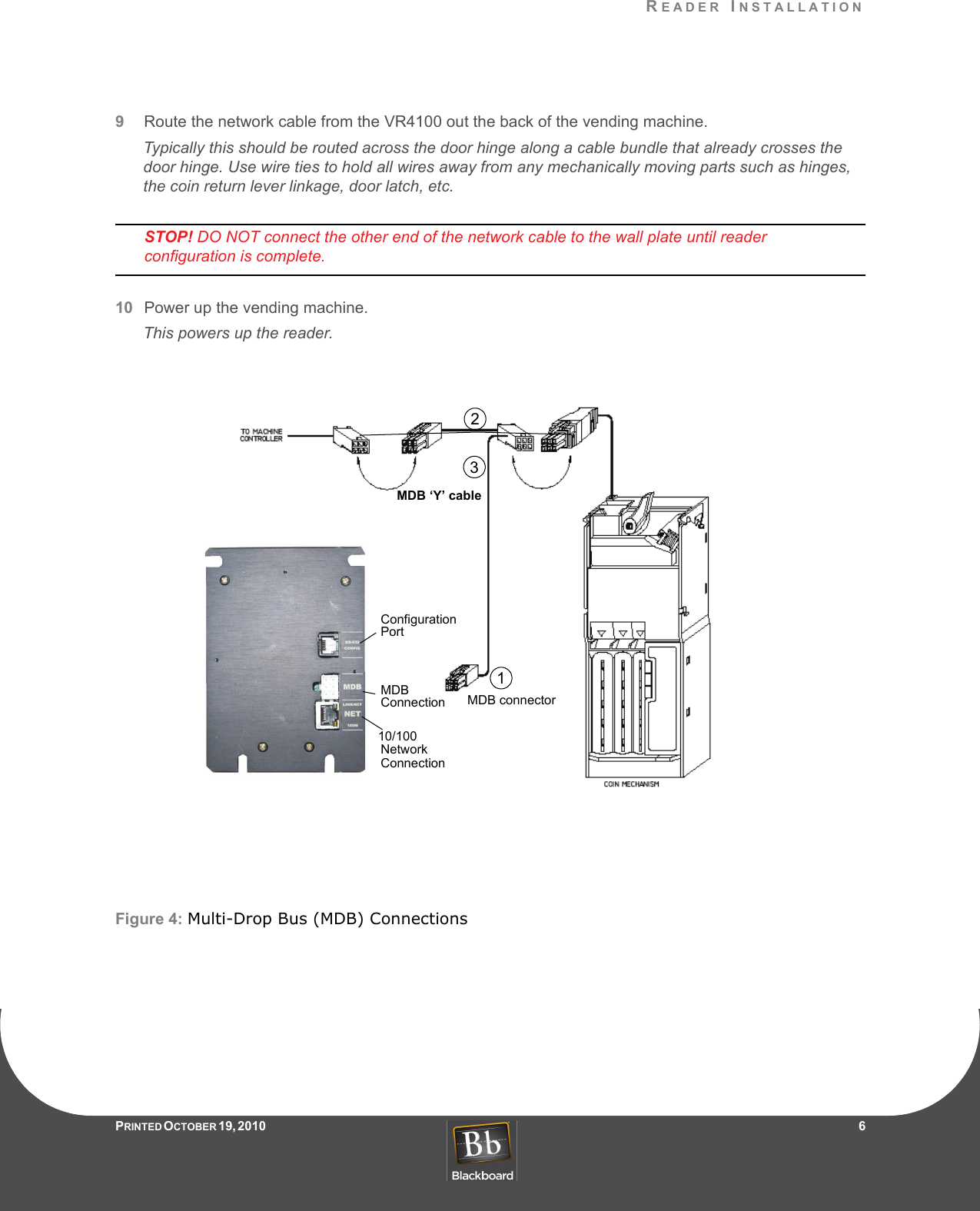
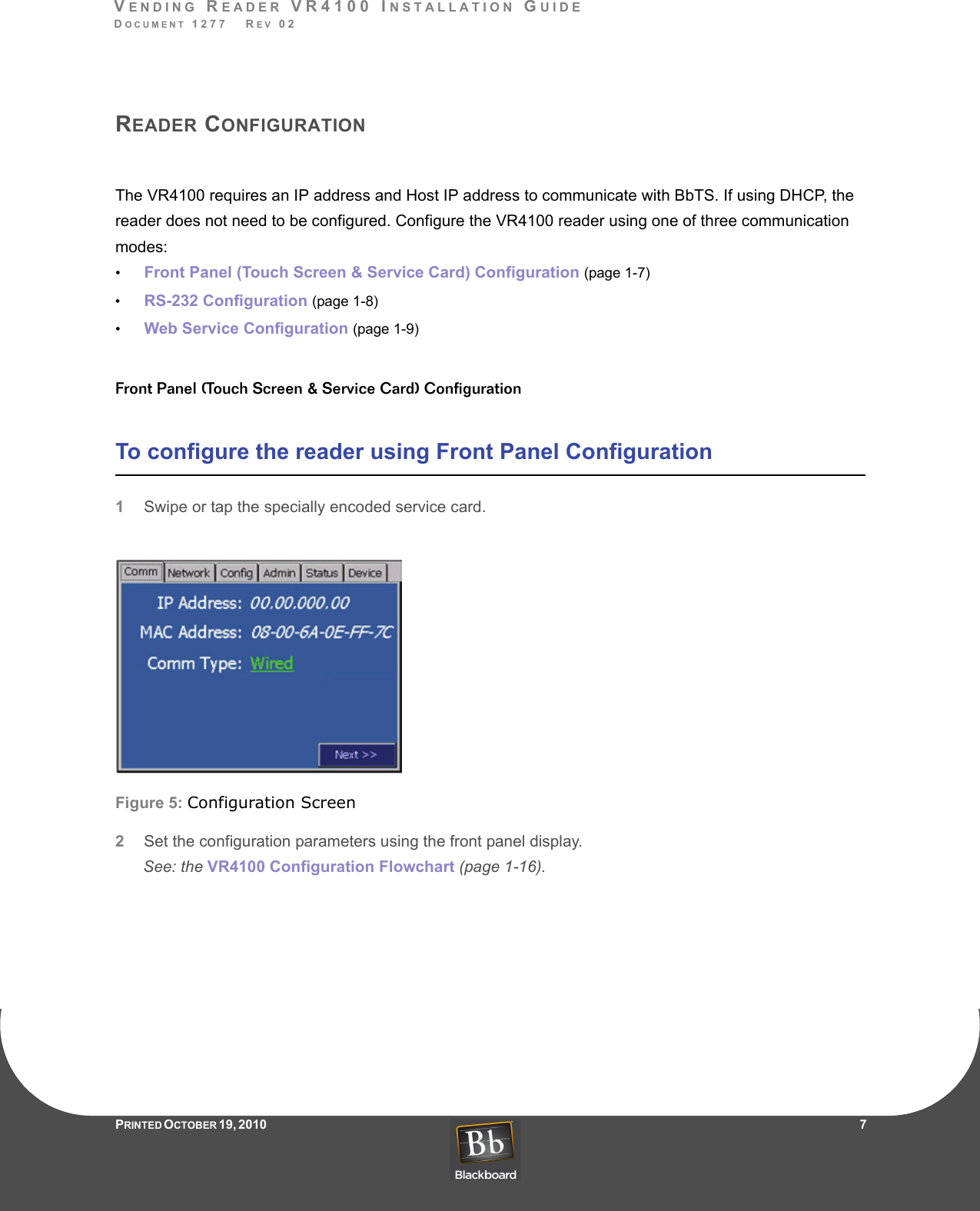
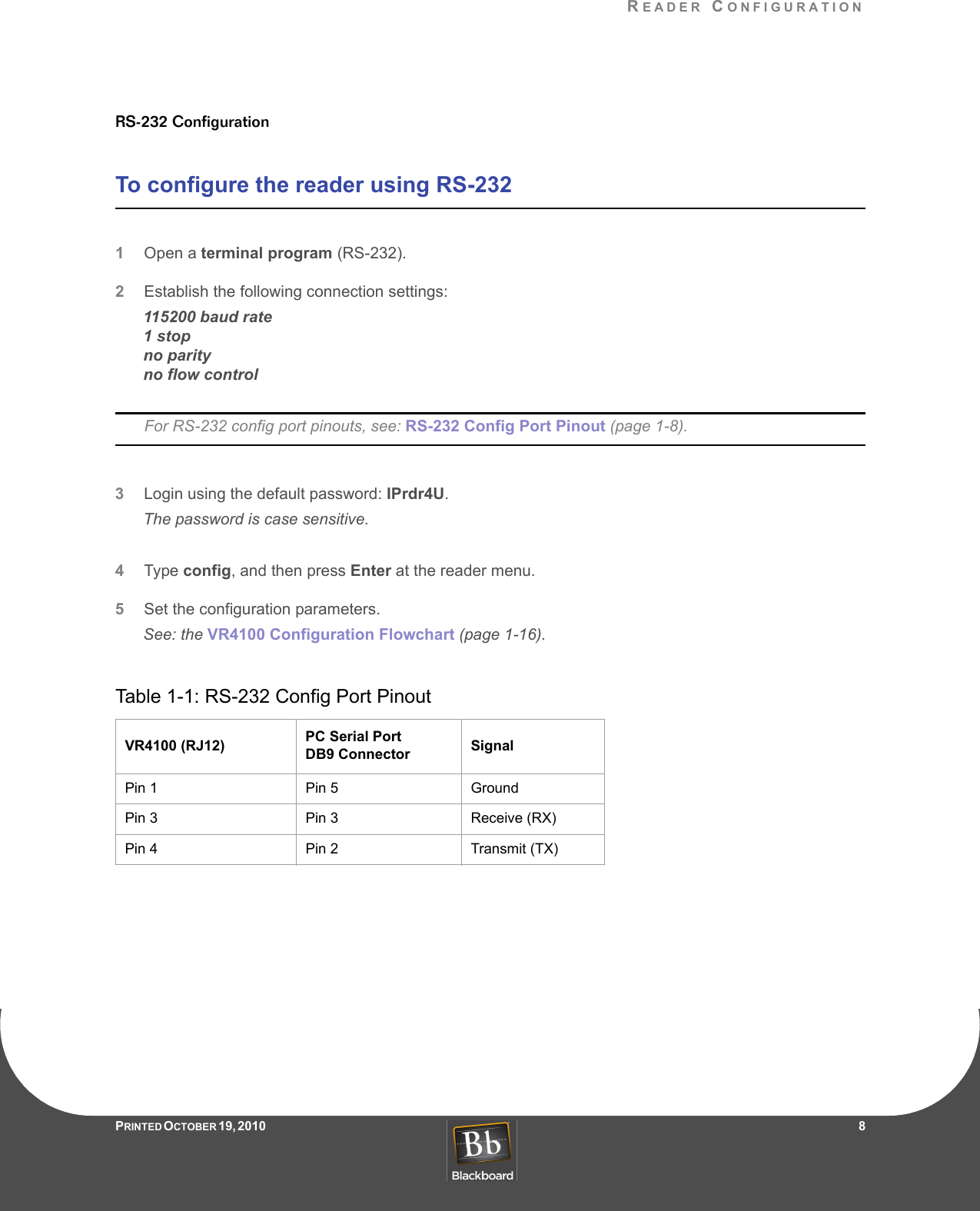
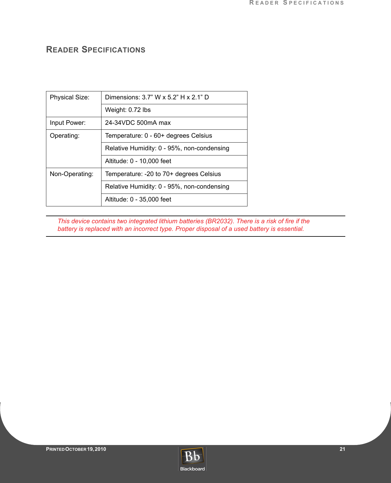
Installation Manual
Navigation menu
Upload a User Manual
Namespaces
Wiki Guide
HTML
PDF
Info
Views
User Manual
Discussion / Help
Navigation