Transact Campus VR4101X008 Vending Card Reader User Manual VR4100 InstallGuide
Blackboard Inc. Vending Card Reader VR4100 InstallGuide
Installation Manual
Vending Reader VR4100
Installation Guide

This device complies with Part 15 of the FCC Rules. Operation is subject to the following two conditions: (1) This
device may not cause harmful interference, and (2) this device must accept any interference received, including
interference that may cause undesired operation.
Part 15.21: Changes or modifications not expressly approved by the party responsible for compliance could void the user’s
authority to operate the equipment.
NOTE: The manufacturer is not responsible for any radio or TV interference caused by unauthorized modifications to this
equipment. Such modifications could void the user’s authority to operate the equipment.
This equipment complies with the FCC radiation exposure limits set forth for an uncontrolled environment. End users must
follow the specific operating instructions for satisfying RF exposure compliance. The antenna(s) used for this transmitter must
be installed to provide a separation distance of at least 20 cm from all persons and must not be co-located or operating in
conjunction with any other antenna or transmitter.
This Class B digital apparatus complies with
Canadian ICES-003
Cet appareill numérique de la classes B est conform
à la norme NMB-003 du Canada

CONTENTS
PRINTED O CTOBER 19, 2010 I
1VENDING READER VR4100 INSTALLATION GUIDE
1 Overview
4 Reader Installation
7 Reader Configuration
7 Front Panel (Touch Screen & Service Card) Configuration
8 RS-232 Configuration
9 Web Service Configuration
10 Setup
12 Monitor
14 Audit
15 Admin
17 Reader Test
18 Reader Audit
20 Reader Factory Default Settings
21 Reader Specifications

FIGURES
PRINTED O CTOBER 19, 2010 II
Figure 1: What’s included ..........................................................................................1
Figure 2: Setup Overview ..........................................................................................3
Figure 3: Vending Reader Face and Mounting Dimensions ......................................5
Figure 4: Multi-Drop Bus (MDB) Connections ...........................................................6
Figure 5: Configuration Screen..................................................................................7
Figure 6: Web Service Login Window .......................................................................9
Figure 7: Web Service Main Menu Options...............................................................9
Figure 8: Setup Menu Options Window...................................................................10
Figure 9: Setup Network Options Window...............................................................10
Figure 10: Setup Reader Options Window ................................................................11
Figure 11: Monitor Menu Options..............................................................................12
Figure 12: Log Detail .................................................................................................12
Figure 13: Network Status .........................................................................................13
Figure 14: System Status ..........................................................................................13
Figure 15: Status (reader status) ...............................................................................14
Figure 16: Reader Audit Window...............................................................................14
Figure 17: Admin Options Window ............................................................................15
Figure 18: VR4100 Configuration Flowchart .............................................................16
Figure 19: Audit Totals Main Screen..........................................................................18
Figure 20: Cumulative Totals Screen.........................................................................18
Figure 21: Interval Totals Screen...............................................................................19
VENDING READER VR4100 INSTALLATION GUIDE
DOCUMENT 1277 REV 02
PRINTED O CTOBER 19, 2010 1
VENDING READER VR4100 INSTALLATION GUIDE
OVERVIEW
The Blackboard VR4100 Vending Reader supports both swipe and contactless card technology. The
vending reader allows MDB vending machines to be used with Blackboard Transaction System (BbTS),
and uses an ethernet connection to communicate to the host server. Communication of host downloads
and reader transactions use a maintained Transport Layer Security (TLS) Secure Communication Channel
to meet PCI Compliance.
The VR4100 Vending Reader can be used in any vending machine that complies with the National
Automated Merchandising Association Multi-Drop Bus (NAMA MDB) interface specification. Many vending
machines manufactured today support this interface.
A specially encoded service card is required to configure the VR4100 reader. Service cards
are ordered separately.
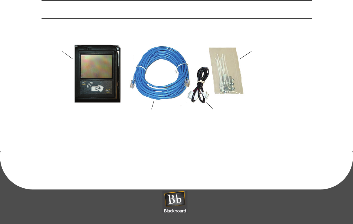
Figure 1: What’s included
CAT5 Cable (25’)
Hardware Kit
MDB Y-Cable
Nuts, Washers,
Wires ties & Standoffs
VR4100
Reader

OVERVIEW
PRINTED O CTOBER 19, 2010 2
READER FEATURES
• The reader works with a Microsoft Windows based Transaction System
• Configuration accessible via front panel (Touch Screen), CONFIG port or Web Service
• Stores up to 2500 off-line transactions
• Allows mixed card and cash vends (if supported by machine controller software)
• Interfaces to all NAMA MDB compliant vending machines
• Mounts easily in bill acceptor or comparable sized opening
• Reduces interference problems with limited size inside machine
• Two simple connections: machine controller/coin mechanism and network
• Volume can be set to off, quiet or loud
• Front panel (Touch Screen) and Web Service access can be disabled for added security
• All IP communications encrypted and authenticated for data security
• Tracks cash sales (if supported by machine controller software)
• Displays balance, account warnings, and other messages following vend
• Wireless 802.11b/g with WPA2 security (AES-CCMP encryption, PSK authentication)
For specifications, see: Reader Specifications (Page: 21).
OBJECTIVES
After reading this guide you can:
• Install the vending reader • Configure the vending reader
• Test the vending reader • Reset reader factory defaults
VENDING READER VR4100 INSTALLATION GUIDE
DOCUMENT 1277 REV 02
PRINTED O CTOBER 19, 2010 3
SETUP OVERVIEW
Figure 2: Setup Overview
1. Configure the reader in BbTS.
See: the Transaction System Administration Guide
2. Reader Installation (page 1-4).
3. Reader Configuration (page 1-7).
4. Reader Test (page 1-17).
READER INSTALLATION
PRINTED O CTOBER 19, 2010 4
READER INSTALLATION
All wiring should be completed by a trained electronic technician.
To install the reader
1Power down the vending machine.
Refer to the vending machine operation manual.
2Prepare a 3.3" x 4.2" cut-out (slightly larger allows reader to fit easily), and then drill four
3/16" holes for mounting studs in the center locations of the slots.
See: the Vending Reader Face and Mounting Dimensions (page 1-5).
If replacing an existing bill acceptor, remove the bill acceptor.
If installing in a pre-cut opening, remove the filler plate.
3Slide the face of the reader through the opening from the inside of the machine.
If using a mounting plate, slide it over the face of the reader from the outside of the machine.
4Install four flat washers and four nuts or threaded standoffs onto the threaded studs to secure the
reader.
If installing in a non-conductive panel in the vending machine (such as a plastic front panel), a
customer supplied ground wire should be connected from one of the mounting studs to a grounded
metal part inside the machine.
Data cables are susceptible to electrical noise that can corrupt data. Avoid routing cables near
electrical equipment, including fluorescent lights, compressors, and motors.
VENDING READER VR4100 INSTALLATION GUIDE
DOCUMENT 1277 REV 02
PRINTED O CTOBER 19, 2010 5
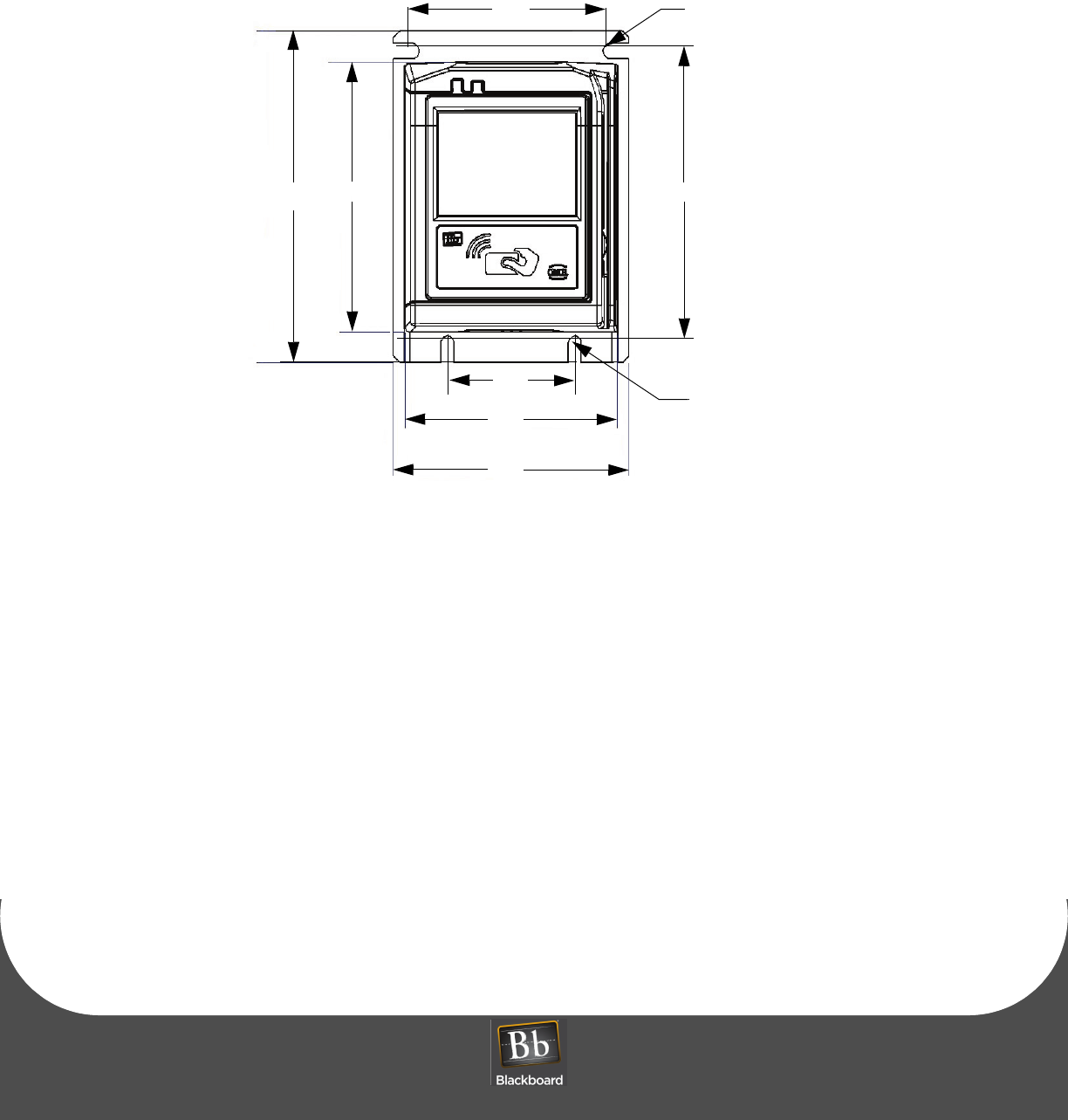
Figure 3: Vending Reader Face and Mounting Dimensions
CONNECT THE READER CABLES
5Connect the single connector end of the supplied MDB 'Y' cable (p/n 055-800-132) to the MDB
connector on the back of the VR4100 reader.
6Disconnect the coin mechanism MDB connector from the machine controller; note the connection
location.
7Connect the double connector end of the supplied MDB 'Y' cable to a.) the coin mechanism MDB
connector, and b.) the machine controller MDB connector.
A 16' MDB extension cable (VE/MDBDPCE16) is available from Blackboard if the supplied 30" cable is
not long enough.
8Connect one end of the supplied CAT5 network cable into the reader:
Ethernet connection (10/100Base-T): 'NET' port
The network cable is a CAT5 patch cable with RJ45 connectors on each end.
3.10”
2”
4.6”
.250” DIAMETER SLOT
2 PLACES
.200” DIAMETER SLOT
2 PLACES
4.23”
5.20”
3.33”
3.70”
READER INSTALLATION
PRINTED O CTOBER 19, 2010 6
9Route the network cable from the VR4100 out the back of the vending machine.
Typically this should be routed across the door hinge along a cable bundle that already crosses the
door hinge. Use wire ties to hold all wires away from any mechanically moving parts such as hinges,
the coin return lever linkage, door latch, etc.
STOP! DO NOT connect the other end of the network cable to the wall plate until reader
configuration is complete.
10 Power up the vending machine.
This powers up the reader.
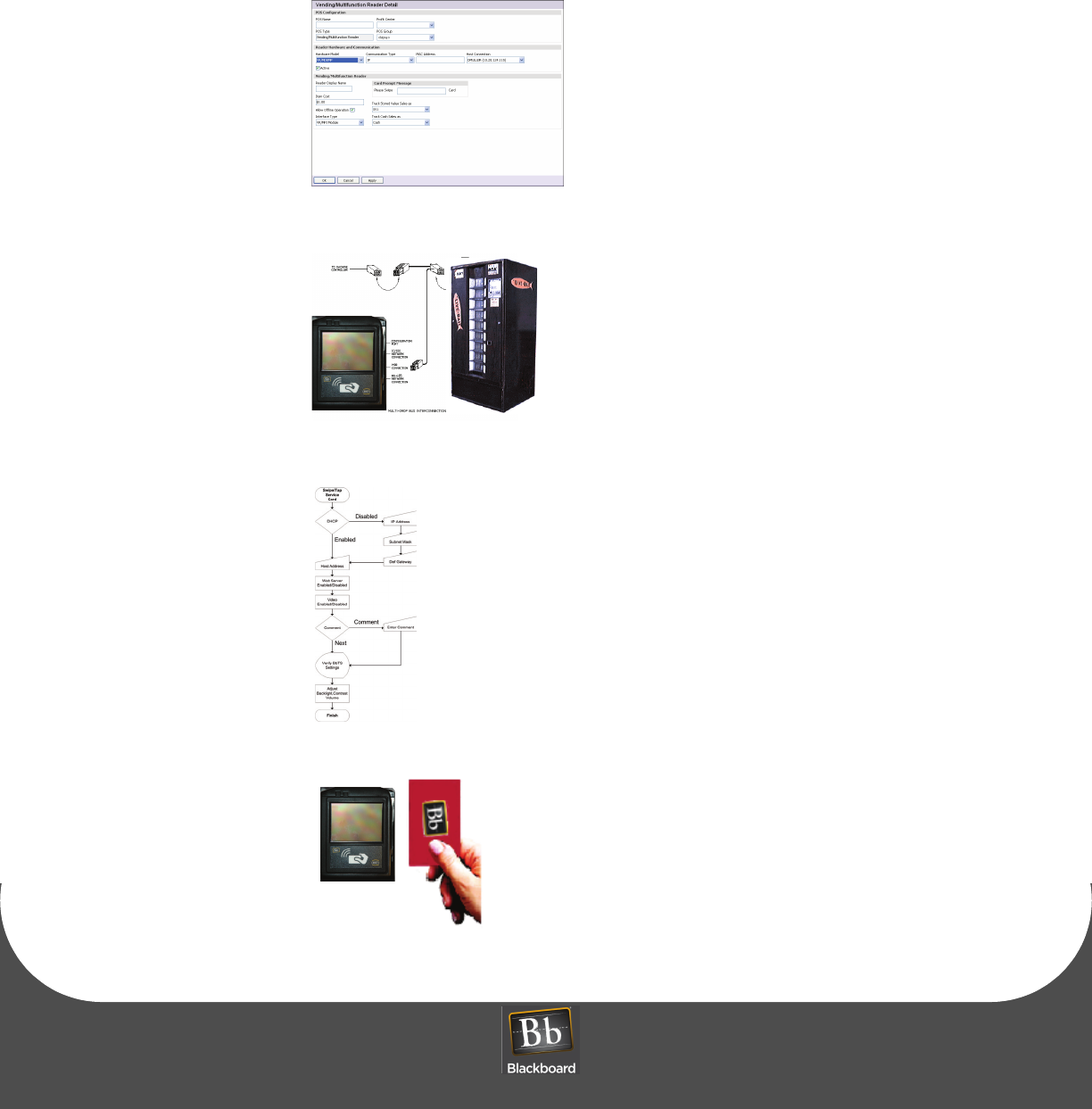
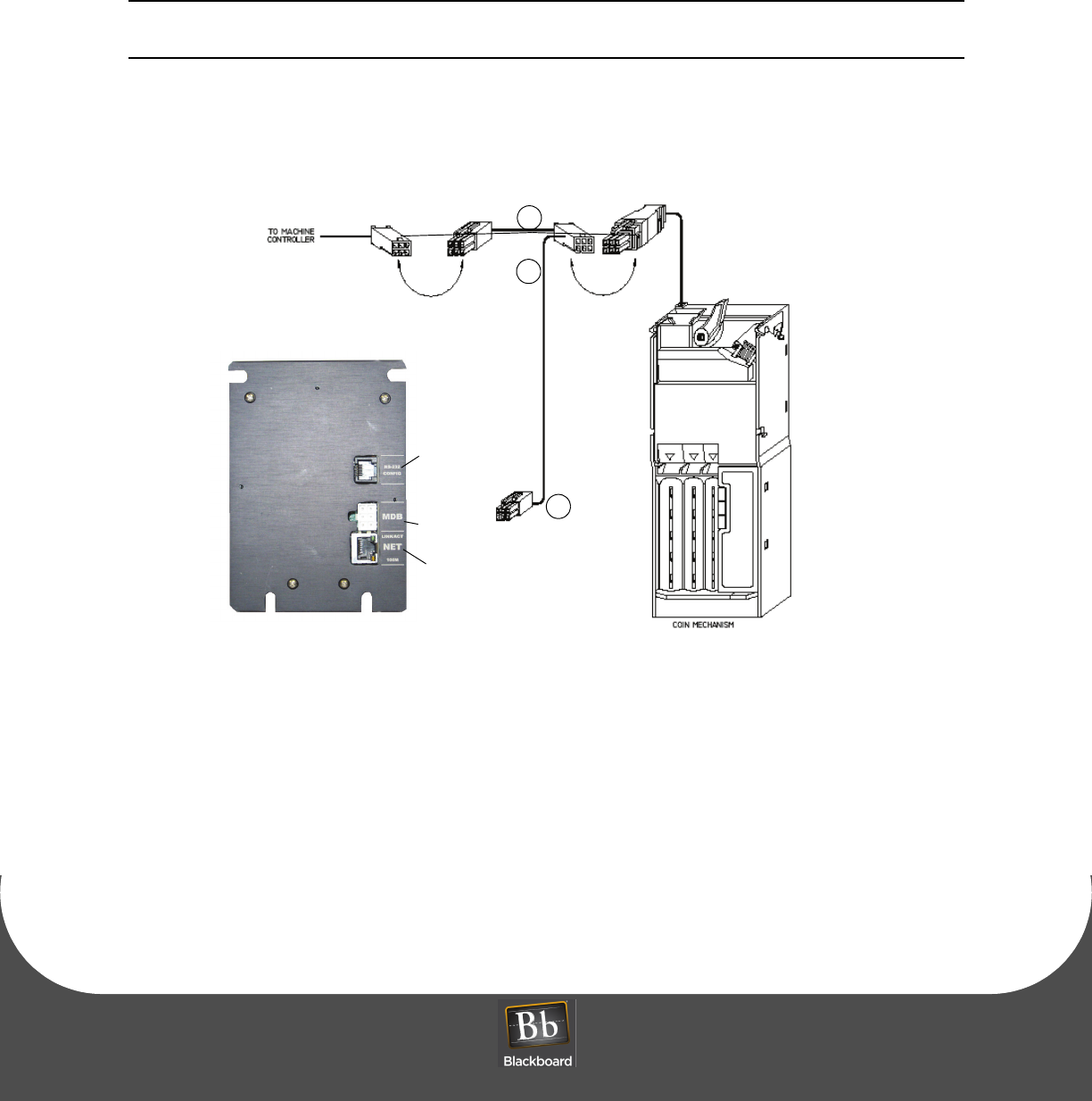
Figure 4: Multi-Drop Bus (MDB) Connections
MDB ‘Y’ cable
MDB connector
1
2
3
Configuration
Port
10/100
Network
Connection
MDB
Connection
4
VENDING READER VR4100 INSTALLATION GUIDE
DOCUMENT 1277 REV 02
PRINTED O CTOBER 19, 2010 7
READER CONFIGURATION
The VR4100 requires an IP address and Host IP address to communicate with BbTS. If using DHCP, the
reader does not need to be configured. Configure the VR4100 reader using one of three communication
modes:
•Front Panel (Touch Screen & Service Card) Configuration (page 1-7)
•RS-232 Configuration (page 1-8)
•Web Service Configuration (page 1-9)
Front Panel (Touch Screen & Service Card) Configuration
To configure the reader using Front Panel Configuration
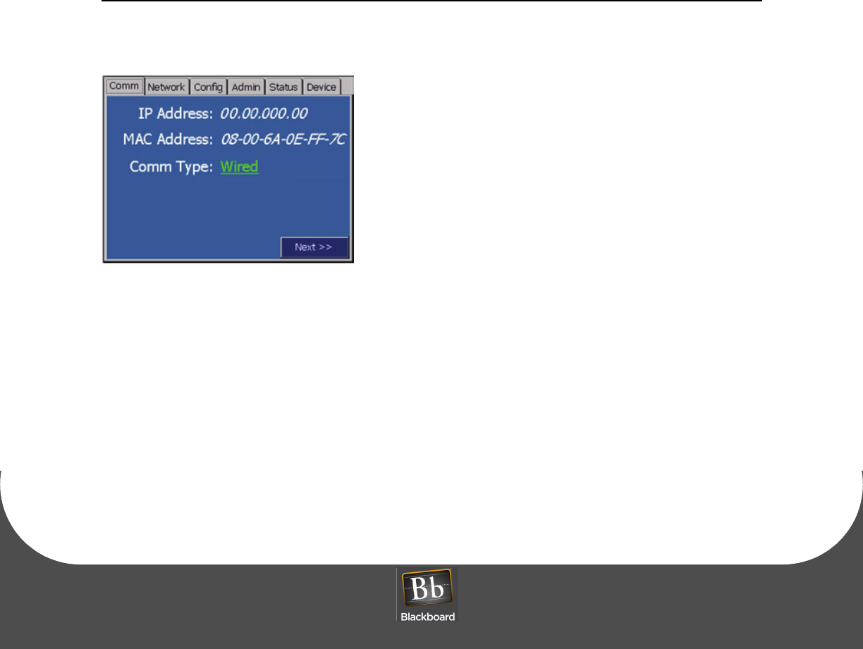
1Swipe or tap the specially encoded service card.
Figure 5: Configuration Screen
2Set the configuration parameters using the front panel display.
See: the VR4100 Configuration Flowchart (page 1-16).
READER CONFIGURATION
PRINTED O CTOBER 19, 2010 8
RS-232 Configuration
To configure the reader using RS-232
1Open a terminal program (RS-232).
2Establish the following connection settings:
115200 baud rate
1 stop
no parity
no flow control
For RS-232 config port pinouts, see: RS-232 Config Port Pinout (page 1-8).
3Login using the default password: IPrdr4U.
The password is case sensitive.
4Type config, and then press Enter at the reader menu.
5Set the configuration parameters.
See: the VR4100 Configuration Flowchart (page 1-16).
Table 1-1: RS-232 Config Port Pinout
VR4100 (RJ12) PC Serial Port
DB9 Connector Signal
Pin 1 Pin 5 Ground
Pin 3 Pin 3 Receive (RX)
Pin 4 Pin 2 Transmit (TX)
VENDING READER VR4100 INSTALLATION GUIDE
DOCUMENT 1277 REV 02
PRINTED O CTOBER 19, 2010 9
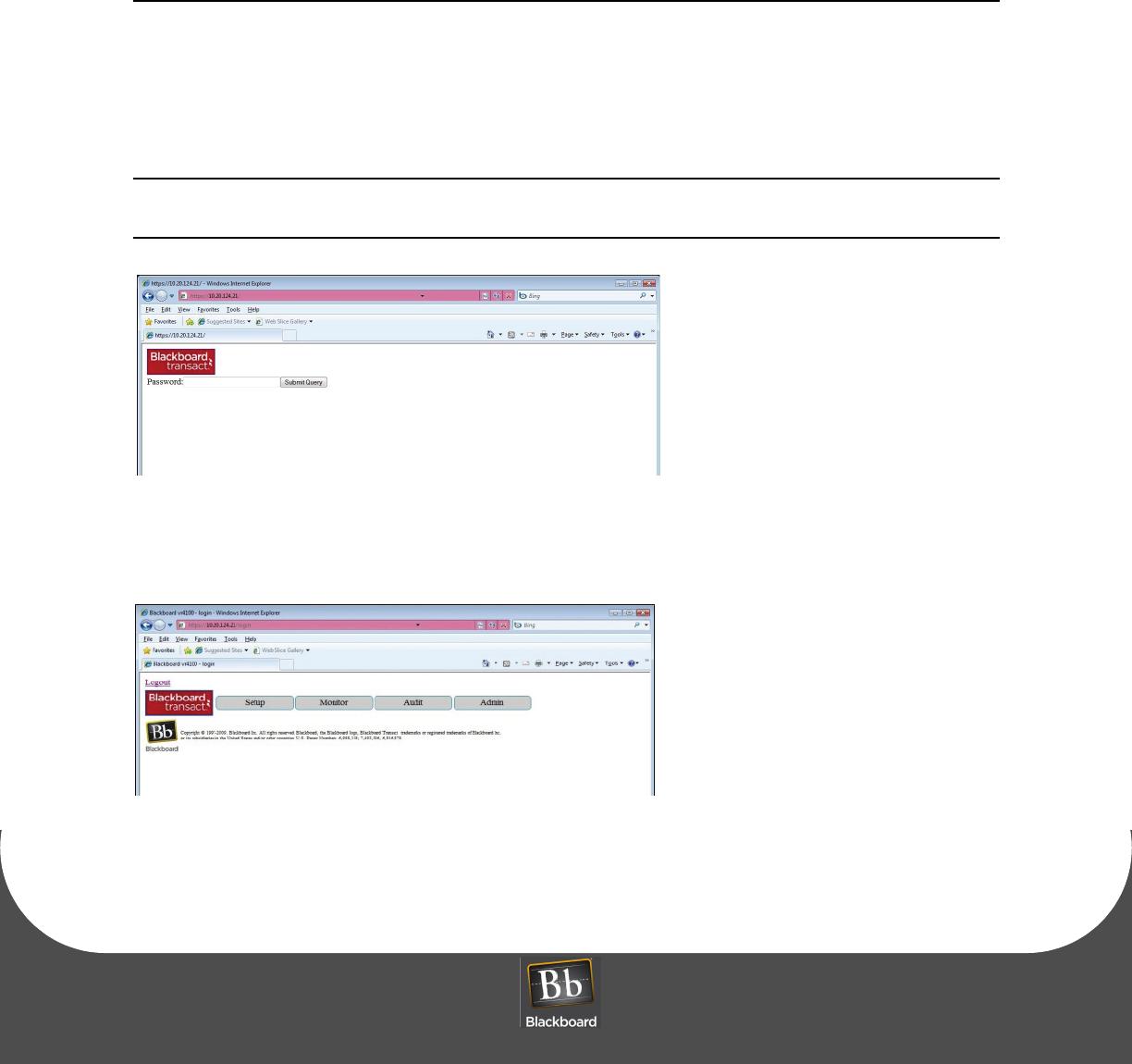
Web Service Configuration
The web server is a secure server that requires Hypertext Transfer Protocol Secure (HTTPS) connections.
When connecting to the web server, in the address bar, replace HTTP:// with HTTPS:// before entering the
IP address.
To configure the reader using web service
1Connect the VR4100 Reader to the network.
2Open a web browser, and then enter the reader’s IP address in the address bar.
Press Enter.
The web server has a self-signed certificate that is not a trusted CA Root certificate. This
causes the browser to report a certificate error, click continue to this website.
Figure 6: Web Service Login Window
3Login using the default password: IPrdr4U.
The password is case sensitive.
Figure 7: Web Service Main Menu Options
READER CONFIGURATION
PRINTED O CTOBER 19, 2010 10
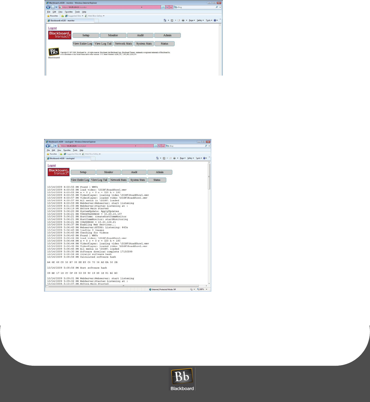
4Choose one of the following menu options:
Setup (Page: 10)
Monitor (Page: 12)
Audit (Page: 14)
Admin (Page: 15)
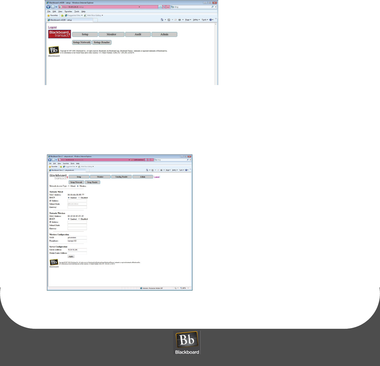
Setup
Figure 8: Setup Menu Options Window
5Choose to:
Setup Network (Page: 10).
Setup Reader (Page: 11).
SETUP NETWORK
Figure 9: Setup Network Options Window
VENDING READER VR4100 INSTALLATION GUIDE
DOCUMENT 1277 REV 02
PRINTED O CTOBER 19, 2010 11
6For a wired network, choose Network Wired.
For a wireless network, choose Network Wireless.
Before configuring the reader (wired or wireless mode), ensure that the VR4100 reader is NOT
connected via a CAT5 network port such as a switch.
7Enter the Network Information.
IP Address
Subnet Mask
Gateway
8For wireless setup, enter Wireless Configuration.
SSID (the name of the wireless local area network)
Passphrase (must match the wireless access point Passphrase)
9Enter the Server Configuration information.
10 Click Apply, and then reboot the reader.
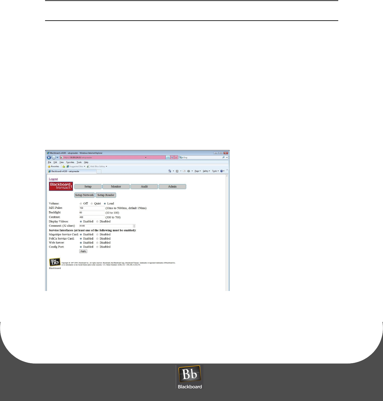
SETUP READER
Figure 10: Setup Reader Options Window
11 Configure the Reader Setup Options, and then click Apply.
VENDING READER VR4100 INSTALLATION GUIDE
DOCUMENT 1277 REV 02
PRINTED O CTOBER 19, 2010 13
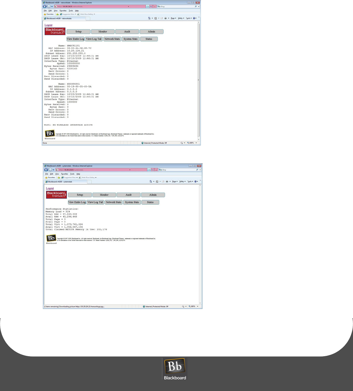
Figure 13: Network Status
Figure 14: System Status
READER CONFIGURATION
PRINTED O CTOBER 19, 2010 14
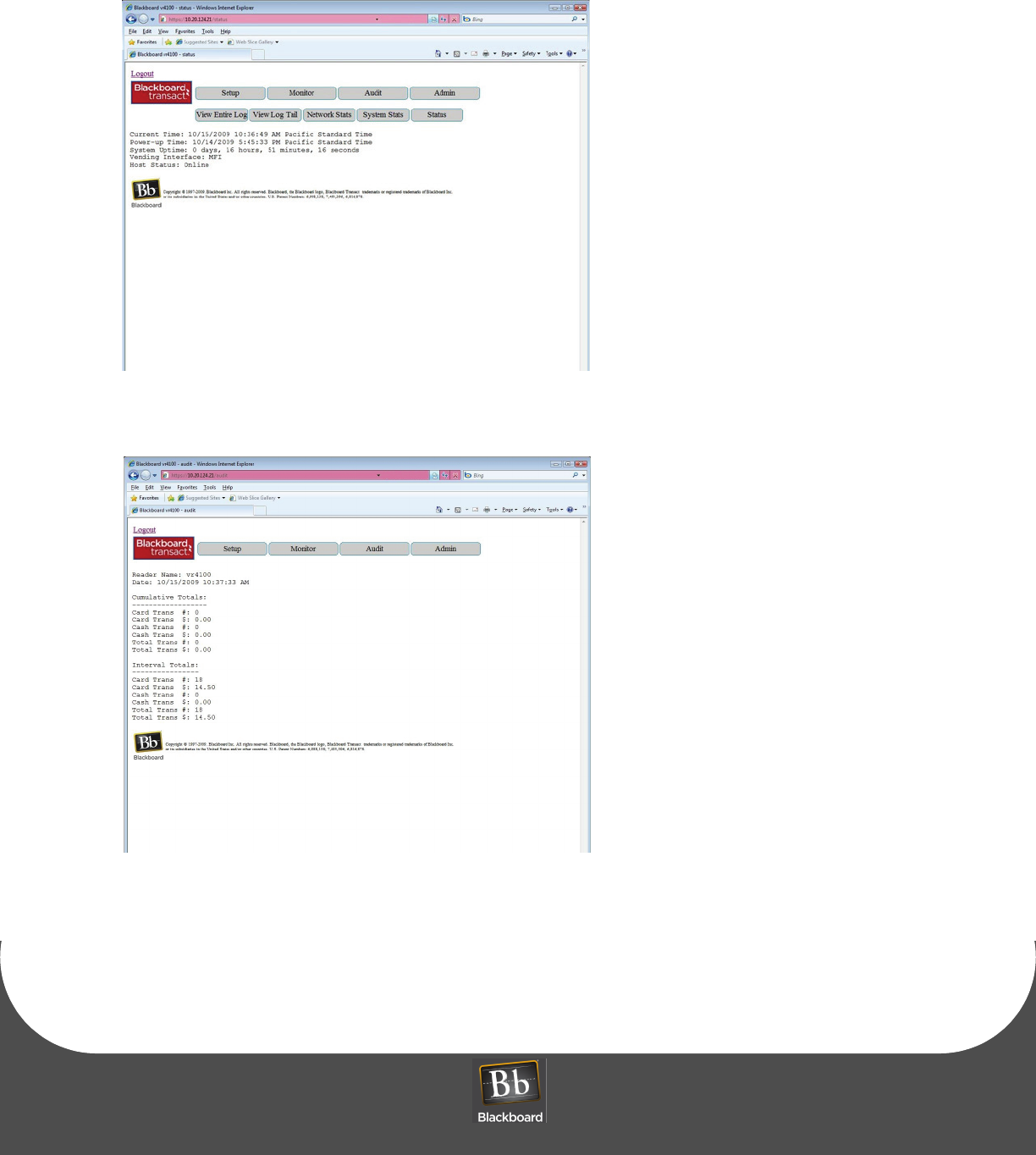
Figure 15: Status (reader status)
Audit
Figure 16: Reader Audit Window
READER CONFIGURATION
PRINTED O CTOBER 19, 2010 15
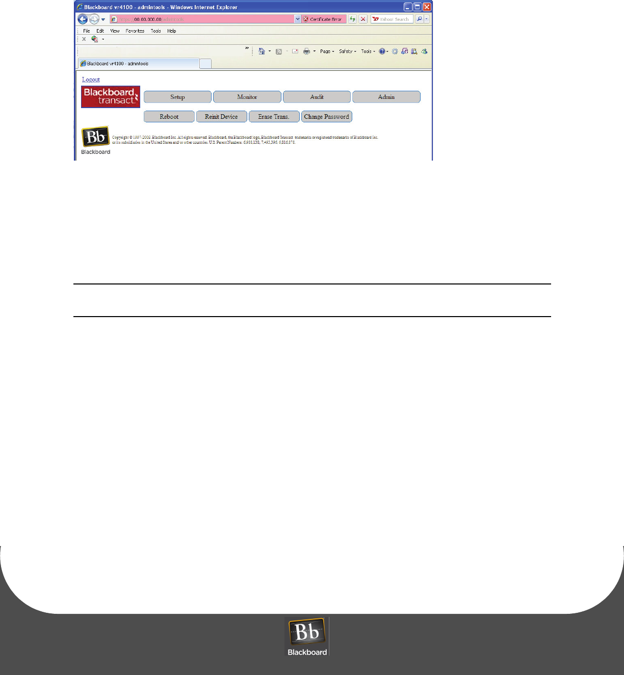
Admin
Figure 17: Admin Options Window
13 Choose to:
Reboot
Reinit Device (clears the reader’s memory)
Erase Trans. (erase transactions)
Change Password
CAUTION!: After a Reinit of the VR4100 Reader with the intention of configuring as wireless
after reboot, ensure that a CAT5 cable is NOT connected to the network.
READER CONFIGURATION
PRINTED O CTOBER 19, 2010 16
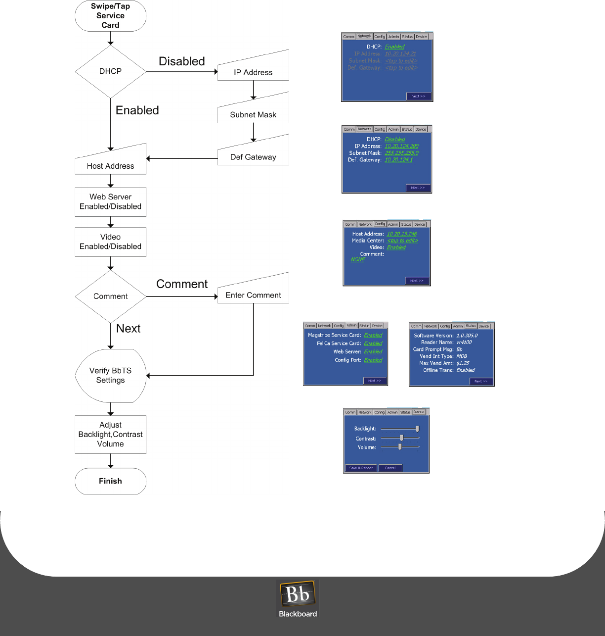
Figure 18: VR4100 Configuration Flowchart
DHCP Enabled
screen
DHCP Disabled
screen
Host/Media/Web/
Video/Comment
screen
BbTS
Verify
Back Light/Contrast/
Volume screen
screens
12
READER TEST
PRINTED O CTOBER 19, 2010 17
READER TEST
To test the reader
1After configuring the reader, connect the other end of the CAT5 network cable into a 10/100 Base-T
network jack.
If 'Out of Service 100' displays, see the vending machine manufacturer for configuring the
machine to support MDB card readers, or to configure the machine to send cash audit
messages to the card reader.
1Swipe or tap a card, and then press CANCEL.
Verify the reader returns to the idle display (Please Swipe or tap xxxxxxxxx Card).
2Insert coins, and then press the coin return lever on the vending machine.
Verify the reader returns to the idle display.
3Insert money (coins or bills), and then select a product that costs less than the amount inserted.
Verify the reader displays the proper amount and returns to the idle display.
4Insert money (coins or bills), and then select a product that costs the exact amount inserted.
Verify the reader displays the proper amount and returns to the idle display.
5Swipe or tap a card, and then select a product that costs less than the maximum credit amount set in
BbTS.
Verify the reader displays the proper amount and returns to the idle display.
6Swipe or tap a card, and then select a product that costs exactly the maximum credit amount set in
BbTS.
Verify the reader displays the proper amount and returns to the idle display.
7In BbTS, verify the test transactions posted properly for each test case.
READER AUDIT
PRINTED O CTOBER 19, 2010 18
READER AUDIT
Reader Audits are implemented at cash collections for reporting collections to the Transaction System. The Audit is
initiated with a Manager Card swipe or tap. The Manager Card provides management and reporting capabilities on
specific remote unattended reader devices. To add a Manager Card, see: the Transaction System Administration
Guide. The reader displays Audit messages at a slow rate for manually recording, about 10 seconds per message.
Once the entire message cycle is complete, the reader reports the date, manager, and amount of cash transactions to
Transaction System and resets interval totals to zero. Amounts are reported on the Net Sales By Location Report.
A Manager Card must be swiped to initialize audit counts.
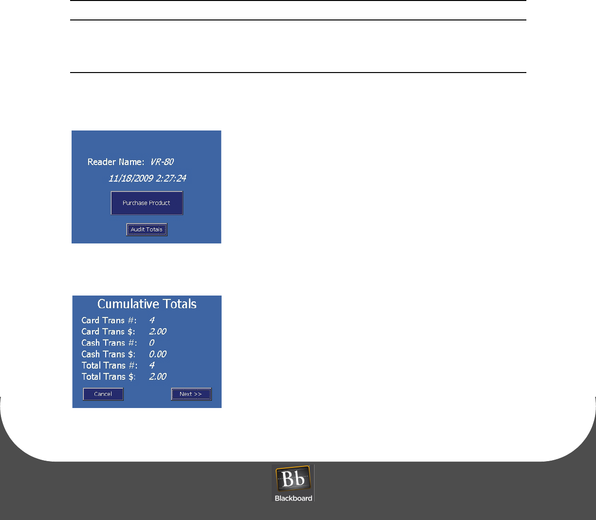
To view audit totals
1Swipe the Manager Card.
2Click Audit Totals.
Figure 19: Audit Totals Main Screen
3Click Cancel to exit, or Next to view the next screen.
Figure 20: Cumulative Totals Screen
READER AUDIT
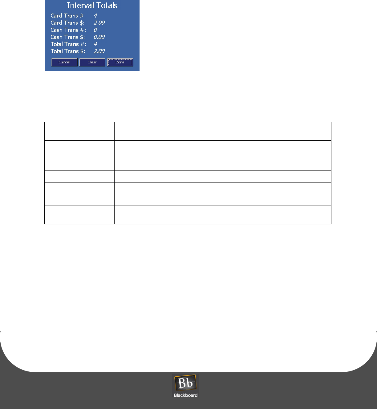
PRINTED O CTOBER 19, 2010 19
4Click to Cancel, Clear or Done to exit.
Figure 21: Interval Totals Screen
Table 1-2: VR4100 Reader Status Messages
Out of Srvc 001 Complete configuration not received by the TS host. Check reader setup and resend
download.
Out of Srvc 002 Off-line transaction storage is full. Bring the reader on-line.
Out of Srvc 100 Complete configuration not received from vending machine Controller. Power cycle
vending machine. Verify Controller supports MDB reader.
Out of Srvc 999 Hardware error. Return reader to Blackboard for service.
Reader Disabled Controller disabled or the machine is out of product.
Card Use Disabled Reader is off-line and off-line transactions are disabled.
Please Swipe or tap
xxxxxxxx card
Reader is ready for use. (xxxxxxxx is the configured TS card name).
READER FACTORY DEFAULT SETTINGS
PRINTED O CTOBER 19, 2010 20
READER FACTORY DEFAULT SETTINGS
Resetting the reader’s default settings restores the original password. This is established by connecting to
the reader’s CONFIG port, or via web server.
To restore factory default settings using the reader’s CONFIG port
1Connect a computer to the reader’s CONFIG port, and then unplug the MDB cable from the reader.
Disconnecting the MDB cable powers down the reader.
2Reconnect the MDB cable, and immediately type a minimum of five ASCII x characters.
Typing ‘xxxxx’ within 3 seconds of the reader boot process will reset to the default settings.
Press the ‘x’ key multiple times, or if the Keyboard Auto-repeat is enabled, hold it down to
accommodate this device’s longer boot time.
To restore factory default settings via web server
1Open a web browser, and then log into the reader.
See: Web Service Configuration (Page: 9).
2Choose Admin, and then Reinit Device.
CAUTION!: After a Reinit of the VR4100 Reader with the intention of configuring as wireless
after reboot, ensure that a CAT5 cable is NOT connected to the network.
READER SPECIFICATIONS
PRINTED O CTOBER 19, 2010 21
READER SPECIFICATIONS
This device contains two integrated lithium batteries (BR2032). There is a risk of fire if the
battery is replaced with an incorrect type. Proper disposal of a used battery is essential.
Physical Size: Dimensions: 3.7” W x 5.2” H x 2.1” D
Weight: 0.72 lbs
Input Power: 24-34VDC 500mA max
Operating: Temperature: 0 - 60+ degrees Celsius
Relative Humidity: 0 - 95%, non-condensing
Altitude: 0 - 10,000 feet
Non-Operating: Temperature: -20 to 70+ degrees Celsius
Relative Humidity: 0 - 95%, non-condensing
Altitude: 0 - 35,000 feet