Trilliant Networks 5G1100 Wireless Mesh WAN Backhaul User Manual SecureMesh Extender Bridge Installation Guide
Trilliant Networks, Inc. Wireless Mesh WAN Backhaul SecureMesh Extender Bridge Installation Guide
UserManual.wiki
>
Trilliant Networks
>
5G1100 User Manual
>
User Manual
Contents
1.
Manual 1
2.
Manual 2
3.
Manual 3
4.
Manual 4
5.
Manual
6.
Instalation Guide
7.
User Manual
User Manual
Navigation menu
Upload a User Manual
Namespaces
Wiki Guide
HTML
PDF
Info
Views
User Manual
Discussion / Help
Navigation

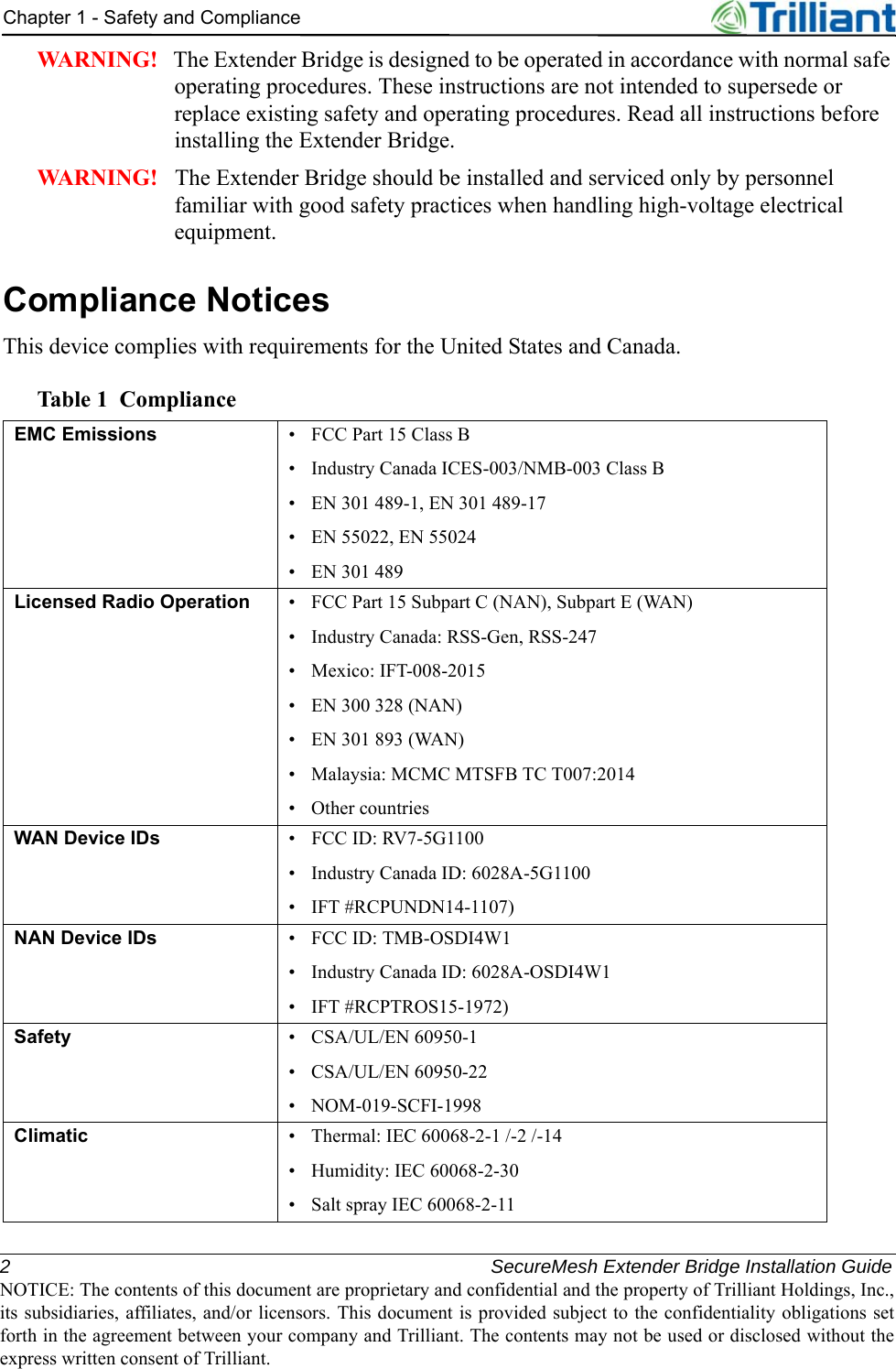

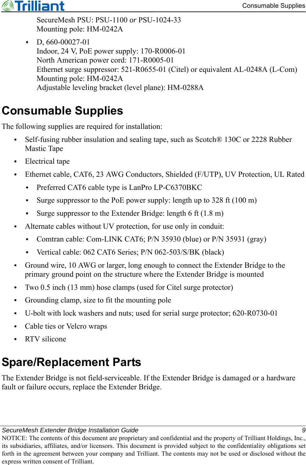
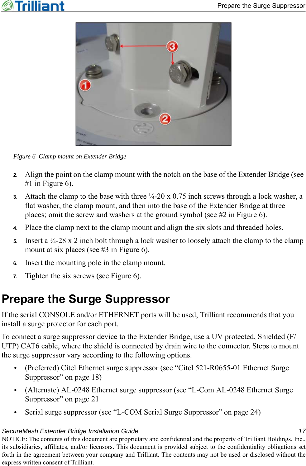
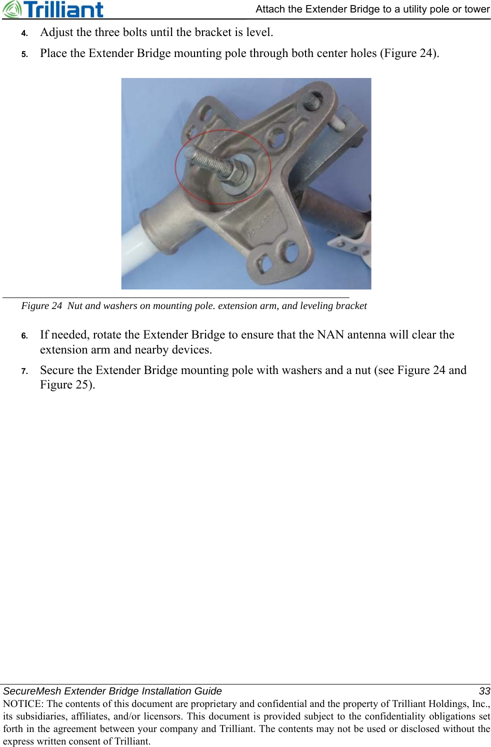
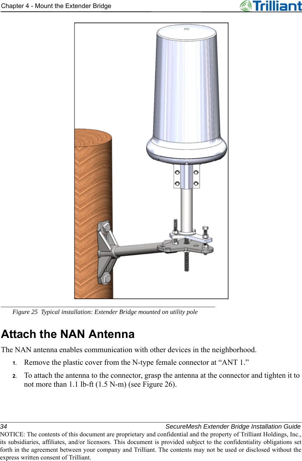
![SecureMesh Extender Bridge Installation Guide 7NOTICE: The contents of this document are proprietary and confidential and the property of Trilliant Holdings, Inc.,its subsidiaries, affiliates, and/or licensors. This document is provided subject to the confidentiality obligations setforth in the agreement between your company and Trilliant. The contents may not be used or disclosed without theexpress written consent of Trilliant.2OverviewThis chapter provides information about the kits, parts, and supplies needed to install the Extender Bridge.Figure 1 Assembled and installed Extender Bridge with Citel surge suppressorThe SecureMesh Extender Bridge combines the functions of an Extender (a SecureMesh Wide Area Network [WAN] relay node) and a Collector (a SecureMesh Neighborhood Area Network](https://usermanual.wiki/Trilliant-Networks/5G1100.User-Manual/User-Guide-3743091-Page-11.png)
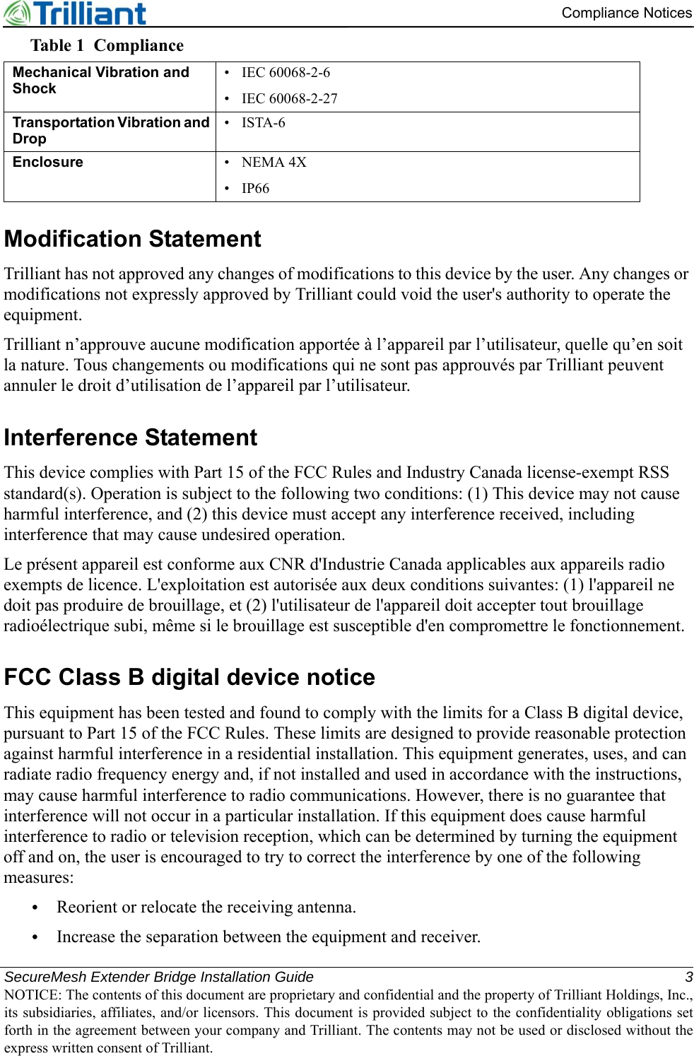
![8 SecureMesh Extender Bridge Installation GuideNOTICE: The contents of this document are proprietary and confidential and the property of Trilliant Holdings, Inc.,its subsidiaries, affiliates, and/or licensors. This document is provided subject to the confidentiality obligations setforth in the agreement between your company and Trilliant. The contents may not be used or disclosed without theexpress written consent of Trilliant.Chapter 2 - Overview[NAN] access point). It routes NAN traffic to and from the UnitySuite Head-End Software (HES) through the WAN.•Extender (WAN) FunctionThe Extender function includes a 5 GHz WAN radio. The radio uses an array of eight, beam-switched, directional antennas to provide full 360° coverage with extended range. It acts as a relay node within the WAN network.The Extender function includes an Ethernet port for WAN client devices. A single client device can connect directly to the WAN, or many client devices can connect through an external IP router or Ethernet switch. If the Extender Bridge uses a SecureMesh Power Service Unit (PSU), the PSU port provides an Ethernet port for WAN client devices.•Collector (NAN) FunctionThe Collector function includes a 2.4 GHz NAN radio with an omnidirectional dipole antenna that provides an access point for other SecureMesh NAN devices.The Collector function supports NAN devices, including electric meters, gas meters, and load control switches, to create a wireless mesh sub-network of the NAN. The Extender Bridge synchronizes time and coordinates the NAN sub-network. The Extender Bridge requires 24 VDC input. Use either a Power over Ethernet (PoE) injector or a PSU.Kits and PartsThe following list includes model numbers for parts and kits.•Extender Bridge: XBRG-1100•Vertical pole mounting bracket: DK-0029A•Mounting pole: HM-00242A•Adjustable leveling bracket: HM-0288A•Ethernet surge suppressor: 521-R0655-01 (Citel) or equivalent AL-0248A (L-Com)•Serial surge suppressor: 620-R0729-01 (use with mounting bracket, 620-R0730-01)•SecureMesh Power Service Unit: PSU-1024-33, PSU-1100, or an uninteruptible power supply (UPS)•Deployment kit for vertical applications; use one of the following:•A, 660-00024-01Indoor, 24 V, PoE power supply: 170-R0006-01North American power cord: 171-R0005-01Ethernet surge suppressor: 521-R0655-01 (Citel) or equivalent AL-0248A (L-Com)•B, 660-00026-01Ethernet surge suppressor: 521-R0655-01 (Citel) or equivalent AL-0248A (L-Com)](https://usermanual.wiki/Trilliant-Networks/5G1100.User-Manual/User-Guide-3743091-Page-12.png)