Trilliant Networks 5G1100 Wireless Mesh WAN Backhaul User Manual SecureMesh Extender Bridge Installation Guide
Trilliant Networks, Inc. Wireless Mesh WAN Backhaul SecureMesh Extender Bridge Installation Guide
Contents
User Manual

NOTICE: The contents of this document are proprietary and confidential and the property of Trilliant Holdings, Inc.,
its subsidiaries, affiliates, and/or licensors. This document is provided subject to the confidentiality obligations set
forth in the agreement between your company and Trilliant. The contents may not be used or disclosed without the
express written consent of Trilliant.
Trilliant Holdings, Inc.
401 Harrison Oaks Blvd.
Cary, NC 27513
SecureMesh Extender
Bridge Installation Guide
For XBRG-1140
Part Number: PL-0066A
Revision: 2.0

i SecureMesh Extender Bridge Installation Guide
NOTICE: The contents of this document are proprietary and confidential and the property of Trilliant Holdings, Inc.,
its subsidiaries, affiliates, and/or licensors. This document is provided subject to the confidentiality obligations set
forth in the agreement between your company and Trilliant. The contents may not be used or disclosed without the
express written consent of Trilliant.
Proprietary Notice
Copyright © Trilliant Holdings, Inc. 2004 – 2018. All rights reserved.
This document describes products, software and services (“Products”) of Trilliant Holdings Inc.,
its subsidiaries, affiliates (collectively, “Trilliant”) and/or its licensors. This document is licensed,
not sold. Except as set out in the License or other written agreement between Trilliant and your
company: (1) the purchase or use of a Product from Trilliant does not convey a license under any
patent rights, copyrights, trademark rights, or any other of the intellectual property rights of
Trilliant or third parties; (2) Trilliant does not assume any responsibility or liability arising out of
the use of this document or any Product it describes; and (3) no part of the document may be
disclosed in any form to any third party.
Trilliant reserves the right to make changes to this document or to any Products it describes at any
time with or without notice.
Use, duplication, or disclosure by the U.S. Government is subject to restrictions of FAR 52.227-
14 (g) (2) (6/87) and FAR 52.227-19 (6/87), or DFAR 252.227-7015 (b) (6/95) and DFAR
227.7202-3 (a).
Trilliant®, SecureMesh®, and UnitySuite® are registered trademarks of Trilliant. Any third-party
name or mark mentioned in this document may be a trademark of its owners.
February 6, 2018

SecureMesh Extender Bridge Installation Guide ii
NOTICE: The contents of this document are proprietary and confidential and the property of Trilliant Holdings, Inc.,
its subsidiaries, affiliates, and/or licensors. This document is provided subject to the confidentiality obligations set
forth in the agreement between your company and Trilliant. The contents may not be used or disclosed without the
express written consent of Trilliant.
Table of Contents
Chapter 1 - Safety and Compliance ........................................................................................................... 1
Safety Information .................................................................................................................................. 1
Compliance Notices ................................................................................................................................ 2
Modification Statement .................................................................................................................... 3
Interference Statement...................................................................................................................... 3
FCC Class B digital device notice.................................................................................................... 3
Wireless notice.................................................................................................................................. 4
WEEE: Waste Electrical and Electronic Equipment Directive ........................................................ 4
Information for Users on Collection and Disposal of Old Equipment ...................................... 4
Information on Disposal in Other Countries Outside the European Union ............................... 4
European Union and European Free Trade Association (EU & EFTA) Compliance Notices ......... 5
Chapter 2 - Overview .................................................................................................................................. 7
Kits and Parts .......................................................................................................................................... 8
Consumable Supplies.............................................................................................................................. 9
Spare/Replacement Parts......................................................................................................................... 9
How to Contact Trilliant ....................................................................................................................... 10
Chapter 3 - Prepare for Installation ........................................................................................................ 11
Tools...................................................................................................................................................... 11
Location Requirements ......................................................................................................................... 11
Grounding Requirements ...................................................................................................................... 12
Grounding Guidelines..................................................................................................................... 12
Grounding Checklist....................................................................................................................... 13
Extender Bridge Components ............................................................................................................... 14
Prepare the Extender Bridge ................................................................................................................. 16
Prepare the Surge Suppressor................................................................................................................ 17
Citel 521-R0655-01 Ethernet Surge Suppressor ............................................................................ 18
L-Com AL-0248 Ethernet Surge Suppressor ................................................................................. 21
L-COM Serial Surge Suppressor.................................................................................................... 24
Set Software Values............................................................................................................................... 27
Extender Parameters ....................................................................................................................... 29
Collector Parameters....................................................................................................................... 29
Chapter 4 - Mount the Extender Bridge.................................................................................................. 31
Attach the Extender Bridge to a utility pole or tower ........................................................................... 31
Attach the NAN Antenna...................................................................................................................... 34
Chapter 5 - Commissioning the Extender Bridge................................................................................... 37
Power and Ground for the Extender Bridge.......................................................................................... 37
Power-up Test........................................................................................................................................ 38
Configuration and Startup ..................................................................................................................... 40
Chapter 6 - Specifications and Pinouts.................................................................................................... 41
Specifications ........................................................................................................................................ 41
Pinouts................................................................................................................................................... 41

iii SecureMesh Extender Bridge Installation Guide
NOTICE: The contents of this document are proprietary and confidential and the property of Trilliant Holdings, Inc.,
its subsidiaries, affiliates, and/or licensors. This document is provided subject to the confidentiality obligations set
forth in the agreement between your company and Trilliant. The contents may not be used or disclosed without the
express written consent of Trilliant.

SecureMesh Extender Bridge Installation Guide 1
NOTICE: The contents of this document are proprietary and confidential and the property of Trilliant Holdings, Inc.,
its subsidiaries, affiliates, and/or licensors. This document is provided subject to the confidentiality obligations set
forth in the agreement between your company and Trilliant. The contents may not be used or disclosed without the
express written consent of Trilliant.
1
Safety and Compliance
This chapter provides safety and compliance information for installers. Before installing the
Extender Bridge, read this whole document.
Safety Information
The caution statements, warning conventions, and warning messages in this section apply to this
product and manual.
Trilliant strongly urges that you always follow all locally-approved safety procedures and safety
instructions when working around high voltage lines and equipment.
The instructions in this manual are not intended as a substitute for proper training in or adequate
experience with safely operating the described equipment. Only competent technicians who are
familiar with this equipment should install or service it. A competent technician:
•Is thoroughly familiar with these instructions
•Is trained in industry-accepted high- and low-voltage safe operating practices and
procedures
•Is trained and authorized to energize, de-energize, clear, and ground power distribution
equipment
•Is trained in the care and use of protective equipment such as flash clothing, safety glasses,
face shields, hardhats, rubber gloves, hotsticks, etc.
The following are important safety instructions. To safely install and operate this equipment, be
sure to read, understand, and follow all caution and warning notices and instructions marked on
the product or included in the documentation.
WARNING! Hazardous voltage. Contact with hazardous voltage will cause death or severe
personal injury. Follow all locally approved safety procedures when working
around high- and low-voltage lines and equipment.

2 SecureMesh Extender Bridge Installation Guide
NOTICE: The contents of this document are proprietary and confidential and the property of Trilliant Holdings, Inc.,
its subsidiaries, affiliates, and/or licensors. This document is provided subject to the confidentiality obligations set
forth in the agreement between your company and Trilliant. The contents may not be used or disclosed without the
express written consent of Trilliant.
Chapter 1 - Safety and Compliance
WARNING! The Extender Bridge is designed to be operated in accordance with normal safe
operating procedures. These instructions are not intended to supersede or
replace existing safety and operating procedures. Read all instructions before
installing the Extender Bridge.
WARNING! The Extender Bridge should be installed and serviced only by personnel
familiar with good safety practices when handling high-voltage electrical
equipment.
Compliance Notices
This device complies with requirements for the United States and Canada.
Table 1 Compliance
EMC Emissions • FCC Part 15 Class B
• Industry Canada ICES-003/NMB-003 Class B
• EN 301 489-1, EN 301 489-17
• EN 55022, EN 55024
• EN 301 489
Licensed Radio Operation • FCC Part 15 Subpart C (NAN), Subpart E (WAN)
• Industry Canada: RSS-Gen, RSS-247
• Mexico: IFT-008-2015
• EN 300 328 (NAN)
• EN 301 893 (WAN)
• Malaysia: MCMC MTSFB TC T007:2014
• Other countries
WAN Device IDs • FCC ID: RV7-5G1100
• Industry Canada ID: 6028A-5G1100
• IFT #RCPUNDN14-1107)
NAN Device IDs • FCC ID: TMB-OSDI4W1
• Industry Canada ID: 6028A-OSDI4W1
• IFT #RCPTROS15-1972)
Safety • CSA/UL/EN 60950-1
• CSA/UL/EN 60950-22
• NOM-019-SCFI-1998
Climatic • Thermal: IEC 60068-2-1 /-2 /-14
• Humidity: IEC 60068-2-30
• Salt spray IEC 60068-2-11

SecureMesh Extender Bridge Installation Guide 3
NOTICE: The contents of this document are proprietary and confidential and the property of Trilliant Holdings, Inc.,
its subsidiaries, affiliates, and/or licensors. This document is provided subject to the confidentiality obligations set
forth in the agreement between your company and Trilliant. The contents may not be used or disclosed without the
express written consent of Trilliant.
Compliance Notices
Modification Statement
Trilliant has not approved any changes of modifications to this device by the user. Any changes or
modifications not expressly approved by Trilliant could void the user's authority to operate the
equipment.
Trilliant n’approuve aucune modification apportée à l’appareil par l’utilisateur, quelle qu’en soit
la nature. Tous changements ou modifications qui ne sont pas approuvés par Trilliant peuvent
annuler le droit d’utilisation de l’appareil par l’utilisateur.
Interference Statement
This device complies with Part 15 of the FCC Rules and Industry Canada license-exempt RSS
standard(s). Operation is subject to the following two conditions: (1) This device may not cause
harmful interference, and (2) this device must accept any interference received, including
interference that may cause undesired operation.
Le présent appareil est conforme aux CNR d'Industrie Canada applicables aux appareils radio
exempts de licence. L'exploitation est autorisée aux deux conditions suivantes: (1) l'appareil ne
doit pas produire de brouillage, et (2) l'utilisateur de l'appareil doit accepter tout brouillage
radioélectrique subi, même si le brouillage est susceptible d'en compromettre le fonctionnement.
FCC Class B digital device notice
This equipment has been tested and found to comply with the limits for a Class B digital device,
pursuant to Part 15 of the FCC Rules. These limits are designed to provide reasonable protection
against harmful interference in a residential installation. This equipment generates, uses, and can
radiate radio frequency energy and, if not installed and used in accordance with the instructions,
may cause harmful interference to radio communications. However, there is no guarantee that
interference will not occur in a particular installation. If this equipment does cause harmful
interference to radio or television reception, which can be determined by turning the equipment
off and on, the user is encouraged to try to correct the interference by one of the following
measures:
•Reorient or relocate the receiving antenna.
•Increase the separation between the equipment and receiver.
Mechanical Vibration and
Shock
• IEC 60068-2-6
• IEC 60068-2-27
Transportation Vibration and
Drop
• ISTA-6
Enclosure • NEMA 4X
• IP66
Table 1 Compliance

4 SecureMesh Extender Bridge Installation Guide
NOTICE: The contents of this document are proprietary and confidential and the property of Trilliant Holdings, Inc.,
its subsidiaries, affiliates, and/or licensors. This document is provided subject to the confidentiality obligations set
forth in the agreement between your company and Trilliant. The contents may not be used or disclosed without the
express written consent of Trilliant.
Chapter 1 - Safety and Compliance
•Connect the equipment into an outlet on a circuit different from that to which the receiver
is connected.
•Consult the dealer or an experienced radio/TV technician for help.
Wireless notice
To satisfy FCC and Industry Canada RF Exposure requirements for mobile and base station
transmission devices, a separation distance of 1 m (39.4 in) or more should be maintained
between the antenna of this device and persons during operation. To ensure compliance, operation
at closer than this distance is not recommended.
Pour satisfaire les requis d'Industrie Canada sur les expositions aux radiofréquences pour les
appareils mobiles et les stations de transmission, une distance de 1 m ou plus doit être maintenue
entre l'antenne de cet appareil et les personnes durant l'opération. Pour assurer la conformité, les
opérations à des distances inférieures ne sont pas recommandées.
WEEE: Waste Electrical and Electronic Equipment Directive
Information for Users on Collection and Disposal of Old Equipment
This symbol on the products, packaging, and/or accompanying documents means that used
electrical and electronic products should not be mixed with general household waste.
For proper treatment, recovery, and recycling of old products, please take them to applicable
collection points, in accordance with your national legislation and the Directives 2012/19/EU.
By disposing of these products correctly, you will help to save valuable resources and prevent any
potential negative effects on human health and the environment which could otherwise arise from
inappropriate waste handling.
For more information about collection and recycling of old products, please contact your local
municipality, your waste disposal service, or the point of sale where you purchased the items.
Information on Disposal in Other Countries Outside the European
Union
This symbol is only valid in the European Union. If you wish to discard these items, please
contact your local authorities or dealer and ask for the correct method of disposal.

SecureMesh Extender Bridge Installation Guide 5
NOTICE: The contents of this document are proprietary and confidential and the property of Trilliant Holdings, Inc.,
its subsidiaries, affiliates, and/or licensors. This document is provided subject to the confidentiality obligations set
forth in the agreement between your company and Trilliant. The contents may not be used or disclosed without the
express written consent of Trilliant.
Compliance Notices
European Union and European Free Trade Association (EU &
EFTA) Compliance Notices
This equipment may be operated in the countries that comprise the member countries of the
European Union and the European Free Trade Association. These countries, listed in the
following paragraph, are referred to as The European Community throughout this document:
AUSTRIA, BELGIUM, BULGARIA, CYPRUS, CZECH REPUBLIC, DENMARK, ESTONIA,
FINLAND, FRANCE, GERMANY, GREECE, HUNGARY, IRELAND, ITALY, LATVIA,
LITHUANIA, LUXEMBOURG, MALTA, NETHERLANDS, POLAND, PORTUGAL,
ROMANIA, SLOVAKIA, SLOVENIA, SPAIN, SWEDEN, UNITED KINGDOM, ICELAND,
LICHTENSTEIN, NORWAY, SWITZERLAND

6 SecureMesh Extender Bridge Installation Guide
NOTICE: The contents of this document are proprietary and confidential and the property of Trilliant Holdings, Inc.,
its subsidiaries, affiliates, and/or licensors. This document is provided subject to the confidentiality obligations set
forth in the agreement between your company and Trilliant. The contents may not be used or disclosed without the
express written consent of Trilliant.
Chapter 1 - Safety and Compliance
SecureMesh Extender Bridge Installation Guide 7
NOTICE: The contents of this document are proprietary and confidential and the property of Trilliant Holdings, Inc.,
its subsidiaries, affiliates, and/or licensors. This document is provided subject to the confidentiality obligations set
forth in the agreement between your company and Trilliant. The contents may not be used or disclosed without the
express written consent of Trilliant.
2
Overview
This chapter provides information about the kits, parts, and supplies needed to install the Extender
Bridge.
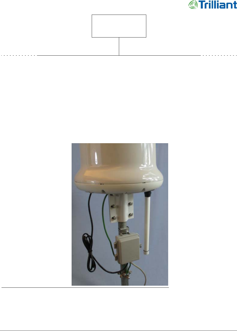
Figure 1 Assembled and installed Extender Bridge with Citel surge suppressor
The SecureMesh Extender Bridge combines the functions of an Extender (a SecureMesh Wide
Area Network [WAN] relay node) and a Collector (a SecureMesh Neighborhood Area Network

8 SecureMesh Extender Bridge Installation Guide
NOTICE: The contents of this document are proprietary and confidential and the property of Trilliant Holdings, Inc.,
its subsidiaries, affiliates, and/or licensors. This document is provided subject to the confidentiality obligations set
forth in the agreement between your company and Trilliant. The contents may not be used or disclosed without the
express written consent of Trilliant.
Chapter 2 - Overview
[NAN] access point). It routes NAN traffic to and from the UnitySuite Head-End Software (HES)
through the WAN.
•Extender (WAN) Function
The Extender function includes a 5 GHz WAN radio. The radio uses an array of eight,
beam-switched, directional antennas to provide full 360° coverage with extended range. It
acts as a relay node within the WAN network.
The Extender function includes an Ethernet port for WAN client devices. A single client
device can connect directly to the WAN, or many client devices can connect through an
external IP router or Ethernet switch. If the Extender Bridge uses a SecureMesh Power
Service Unit (PSU), the PSU port provides an Ethernet port for WAN client devices.
•Collector (NAN) Function
The Collector function includes a 2.4 GHz NAN radio with an omnidirectional dipole
antenna that provides an access point for other SecureMesh NAN devices.
The Collector function supports NAN devices, including electric meters, gas meters, and
load control switches, to create a wireless mesh sub-network of the NAN. The Extender
Bridge synchronizes time and coordinates the NAN sub-network.
The Extender Bridge requires 24 VDC input. Use either a Power over Ethernet (PoE) injector or a
PSU.
Kits and Parts
The following list includes model numbers for parts and kits.
•Extender Bridge: XBRG-1100
•Vertical pole mounting bracket: DK-0029A
•Mounting pole: HM-00242A
•Adjustable leveling bracket: HM-0288A
•Ethernet surge suppressor: 521-R0655-01 (Citel) or equivalent AL-0248A (L-Com)
•Serial surge suppressor: 620-R0729-01 (use with mounting bracket, 620-R0730-01)
•SecureMesh Power Service Unit: PSU-1024-33, PSU-1100, or an uninteruptible power
supply (UPS)
•Deployment kit for vertical applications; use one of the following:
•A, 660-00024-01
Indoor, 24 V, PoE power supply: 170-R0006-01
North American power cord: 171-R0005-01
Ethernet surge suppressor: 521-R0655-01 (Citel) or equivalent AL-0248A (L-Com)
•B, 660-00026-01
Ethernet surge suppressor: 521-R0655-01 (Citel) or equivalent AL-0248A (L-Com)

SecureMesh Extender Bridge Installation Guide 9
NOTICE: The contents of this document are proprietary and confidential and the property of Trilliant Holdings, Inc.,
its subsidiaries, affiliates, and/or licensors. This document is provided subject to the confidentiality obligations set
forth in the agreement between your company and Trilliant. The contents may not be used or disclosed without the
express written consent of Trilliant.
Consumable Supplies
SecureMesh PSU: PSU-1100 or PSU-1024-33
Mounting pole: HM-0242A
•D, 660-00027-01
Indoor, 24 V, PoE power supply: 170-R0006-01
North American power cord: 171-R0005-01
Ethernet surge suppressor: 521-R0655-01 (Citel) or equivalent AL-0248A (L-Com)
Mounting pole: HM-0242A
Adjustable leveling bracket (level plane): HM-0288A
Consumable Supplies
The following supplies are required for installation:
•Self-fusing rubber insulation and sealing tape, such as Scotch® 130C or 2228 Rubber
Mastic Tape
•Electrical tape
•Ethernet cable, CAT6, 23 AWG Conductors, Shielded (F/UTP), UV Protection, UL Rated
•Preferred CAT6 cable type is LanPro LP-C6370BKC
•Surge suppressor to the PoE power supply: length up to 328 ft (100 m)
•Surge suppressor to the Extender Bridge: length 6 ft (1.8 m)
•Alternate cables without UV protection, for use only in conduit:
•Comtran cable: Com-LINK CAT6; P/N 35930 (blue) or P/N 35931 (gray)
•Vertical cable: 062 CAT6 Series; P/N 062-503/S/BK (black)
•Ground wire, 10 AWG or larger, long enough to connect the Extender Bridge to the
primary ground point on the structure where the Extender Bridge is mounted
•Two 0.5 inch (13 mm) hose clamps (used for Citel surge protector)
•Grounding clamp, size to fit the mounting pole
•U-bolt with lock washers and nuts; used for serial surge protector; 620-R0730-01
•Cable ties or Velcro wraps
•RTV silicone
Spare/Replacement Parts
The Extender Bridge is not field-serviceable. If the Extender Bridge is damaged or a hardware
fault or failure occurs, replace the Extender Bridge.

10 SecureMesh Extender Bridge Installation Guide
NOTICE: The contents of this document are proprietary and confidential and the property of Trilliant Holdings, Inc.,
its subsidiaries, affiliates, and/or licensors. This document is provided subject to the confidentiality obligations set
forth in the agreement between your company and Trilliant. The contents may not be used or disclosed without the
express written consent of Trilliant.
Chapter 2 - Overview
How to Contact Trilliant
Use the following methods to contact Trilliant:
General Company and Solution Information: http://www.trilliantinc.com/
Trilliant Headquarters: Tel: 650.204.5050
Solution and Customer Support Portal: https://support.trilliantinc.com/
Note: Make all requests for Solution support or RMA processing through the web portal. If
you do not have a Support Portal login and password, or need your credentials reset,
contact Trilliant Support using the email address below.
E-mail: support@trilliantinc.com
Note: This email address is not a primary means of communicating with Customer Support.
Use it primarily to request access to the Support Portal (or to have access credentials
reset).

SecureMesh Extender Bridge Installation Guide 11
NOTICE: The contents of this document are proprietary and confidential and the property of Trilliant Holdings, Inc.,
its subsidiaries, affiliates, and/or licensors. This document is provided subject to the confidentiality obligations set
forth in the agreement between your company and Trilliant. The contents may not be used or disclosed without the
express written consent of Trilliant.
3
Prepare for Installation
This chapter provides information about the steps to prepare the site and the Extender Bridge for
installation.
Tools
Gather the following tools before starting to install the Extender Bridge:
•Magnetic level, such as McMaster-Carr Magnetic-backed bull’s eye level, part number
3329A31
•Screwdriver: Phillips head, #2 and #3
•Nut drivers: various sizes
•Open-end wrenches: various sizes
•For configuration: a computer with a serial port, a terminal emulation program, a network
interface card, and a Web browser (laptop recommended for convenience)
Location Requirements
Select a location that meets the following access guidelines:
•Conforms to all local electrical codes and ordinances
•Either owned by the utility or where the utility has access rights
•Able to provide adequate power
Note: The 24 V PSU requires 90-265 Vac 50/60 Hz power.
•At least 18 ft (5.5 m) above ground level, although radio performance and coverage
typically improve as the height increases
•If needed, space to use a bucket truck

12 SecureMesh Extender Bridge Installation Guide
NOTICE: The contents of this document are proprietary and confidential and the property of Trilliant Holdings, Inc.,
its subsidiaries, affiliates, and/or licensors. This document is provided subject to the confidentiality obligations set
forth in the agreement between your company and Trilliant. The contents may not be used or disclosed without the
express written consent of Trilliant.
Chapter 3 - Prepare for Installation
•Allows access for normal maintenance
Select a location that meets the following guidelines:
•The radio signals to and from the Extender Bridge within the Fresnel zone will not be not
obstructed.
•Nearby structures do not block line-of-sight radio coverage.
•Clear of thick trees or brush at installation and in the foreseeable future. Foliage in the line
of sight to other devices can degrade radio performance.
•An unobstructed view of the overhead sky for access to the strongest GPS signals. At
startup, the Extender Bridge searches for a GPS signal. If it cannot detect a signal, it
cannot complete startup. establish wireless connections with other SecureMesh WAN
devices, or establish time synchronization.
Grounding Requirements
Identify the primary ground point for the Extender Bridge location.
WARNING! A proper ground protects both the Extender Bridge and the equipment
connected to it. Ground protection is essential if the Extender Bridge is
installed on a tall structure or in an area where lightning occurs.
The techniques described here are general guidelines and do not constitute a comprehensive guide
covering all installation scenarios. For maximum protection, and if lightning is a threat in your
area, consult a specialist in lightning and transient protection who is familiar with your operating
environment.
Grounding Guidelines
To ensure optimal reliability, properly ground the metal base of the Extender Bridge. Use a
10 AWG or larger wire to connect it to the ground point on the structure. This ground point is
especially important if the structure is non-conductive, such as wood or concrete.The three most
common ground points include the following:
•The primary ground point or down lead provided by the existing ground system at the site,
such as a part of the tower structure (see Figure 2) or the AC electrical system for the
building.
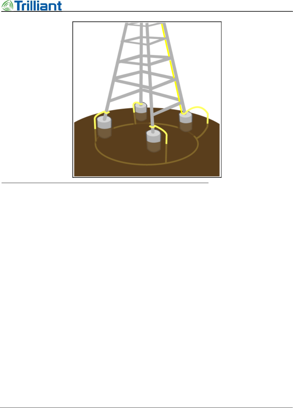
•A copper-clad ground rod, 10 ft (3 m) or longer, driven into the earth. At a tower with
multiple legs, there typically is one ground rod at each leg and a ground wire loop that
connects the rods.
•A cold-water pipe that is well-connected to earth.
SecureMesh Extender Bridge Installation Guide 13
NOTICE: The contents of this document are proprietary and confidential and the property of Trilliant Holdings, Inc.,
its subsidiaries, affiliates, and/or licensors. This document is provided subject to the confidentiality obligations set
forth in the agreement between your company and Trilliant. The contents may not be used or disclosed without the
express written consent of Trilliant.
Grounding Requirements
Figure 2 Tower ground system
In all cases, ensure that the connections can retain low resistance and integrity over time and with
exposure to the elements. Use an antioxidant compound and wrap all connections with a product
such as Scotch® 130C or 2228 Rubber Mastic Tape.
Grounding Checklist
To confirm that the Extender Bridge is adequately protected from power surges and lightning,
check the following items:
•Install all lightning and surge suppression devices in accordance with UL 96A installation
requirements for lightning protection systems and the NFPA 780 standard for lightning
protection.
•Verify that all points of the ground system are tied together with less than 5 Ω resistance
between any two points.
•Attach a ground wire from the Extender Bridge to the ground system on the utility pole,
tower, or building.
•When installing outdoor Ethernet cable, use UV protected, STP, CAT6 cable that includes
a drain wire. Attach the drain wire and the cable shield to the ground lug inside the surge
suppressor. Leave the end of the drain wire at the power source unattached.
•For towers and rooftops, follow these additional requirements:
14 SecureMesh Extender Bridge Installation Guide
NOTICE: The contents of this document are proprietary and confidential and the property of Trilliant Holdings, Inc.,
its subsidiaries, affiliates, and/or licensors. This document is provided subject to the confidentiality obligations set
forth in the agreement between your company and Trilliant. The contents may not be used or disclosed without the
express written consent of Trilliant.
Chapter 3 - Prepare for Installation
•To attach the Extender Bridge on a roof or tower to the ground system, use a 10 AWG
or larger down-lead.
•Route the CAT6 cable inside the tower and tie the cable to the tower leg at 4 ft (1.2 m)
intervals. For increased protection, run the CAT6 cable through metallic conduit
installed on the tower.
Extender Bridge Components
Figure 3 through Figure 5 show the parts of the Extender Bridge kit.
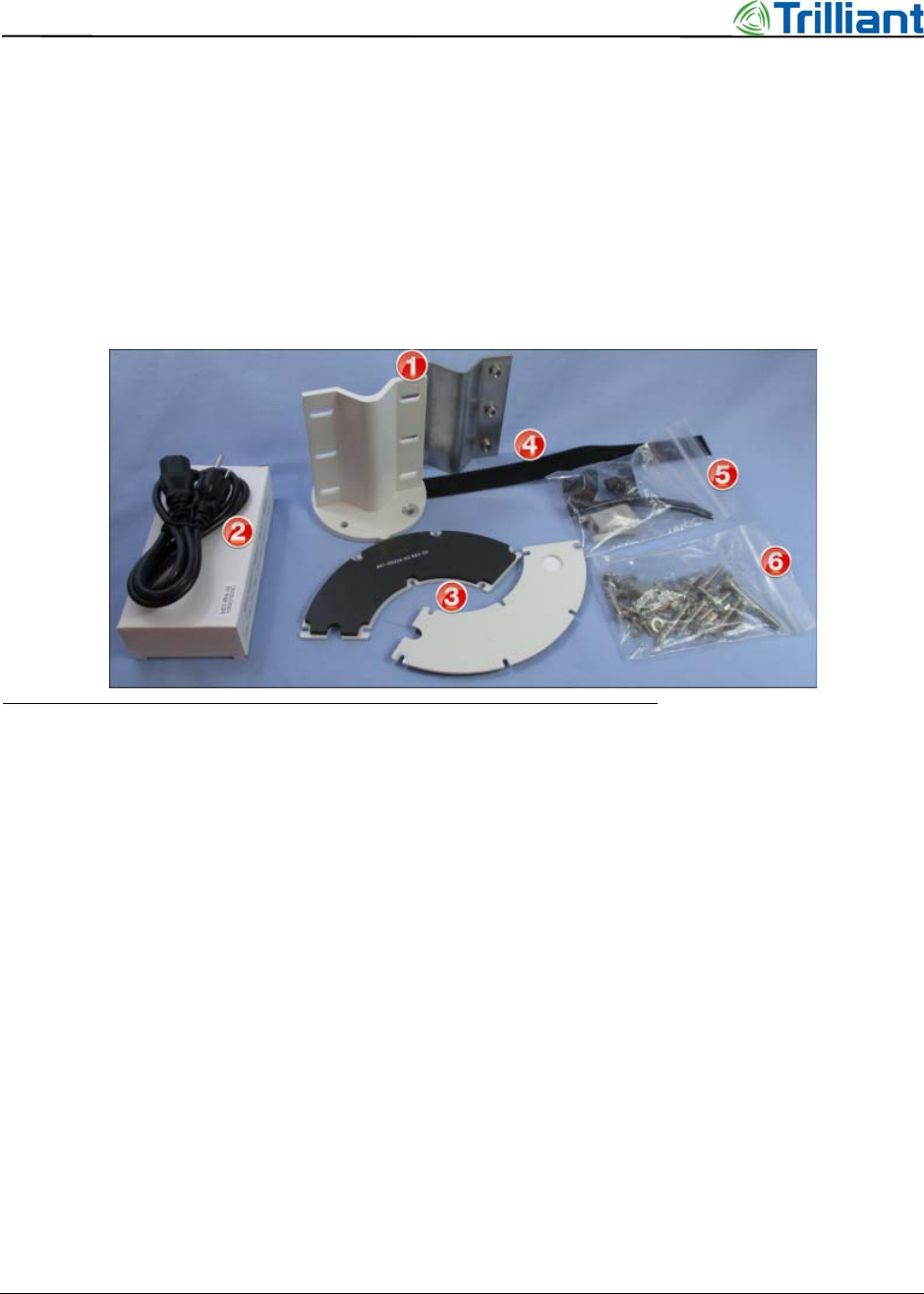
Figure 3 Extender Bridge accessory kit contents
Accessory kit parts:
1. Clamp and clamp mount
2. Power over Ethernet (PoE) injector and power cord
3. Interface door (kit includes one; photo shows both sides)
4. Velcro fastener
5. Accessory bag with miscellaneous parts
6. Accessory bag with screws, bolts, nuts and washers
SecureMesh Extender Bridge Installation Guide 15
NOTICE: The contents of this document are proprietary and confidential and the property of Trilliant Holdings, Inc.,
its subsidiaries, affiliates, and/or licensors. This document is provided subject to the confidentiality obligations set
forth in the agreement between your company and Trilliant. The contents may not be used or disclosed without the
express written consent of Trilliant.
Extender Bridge Components
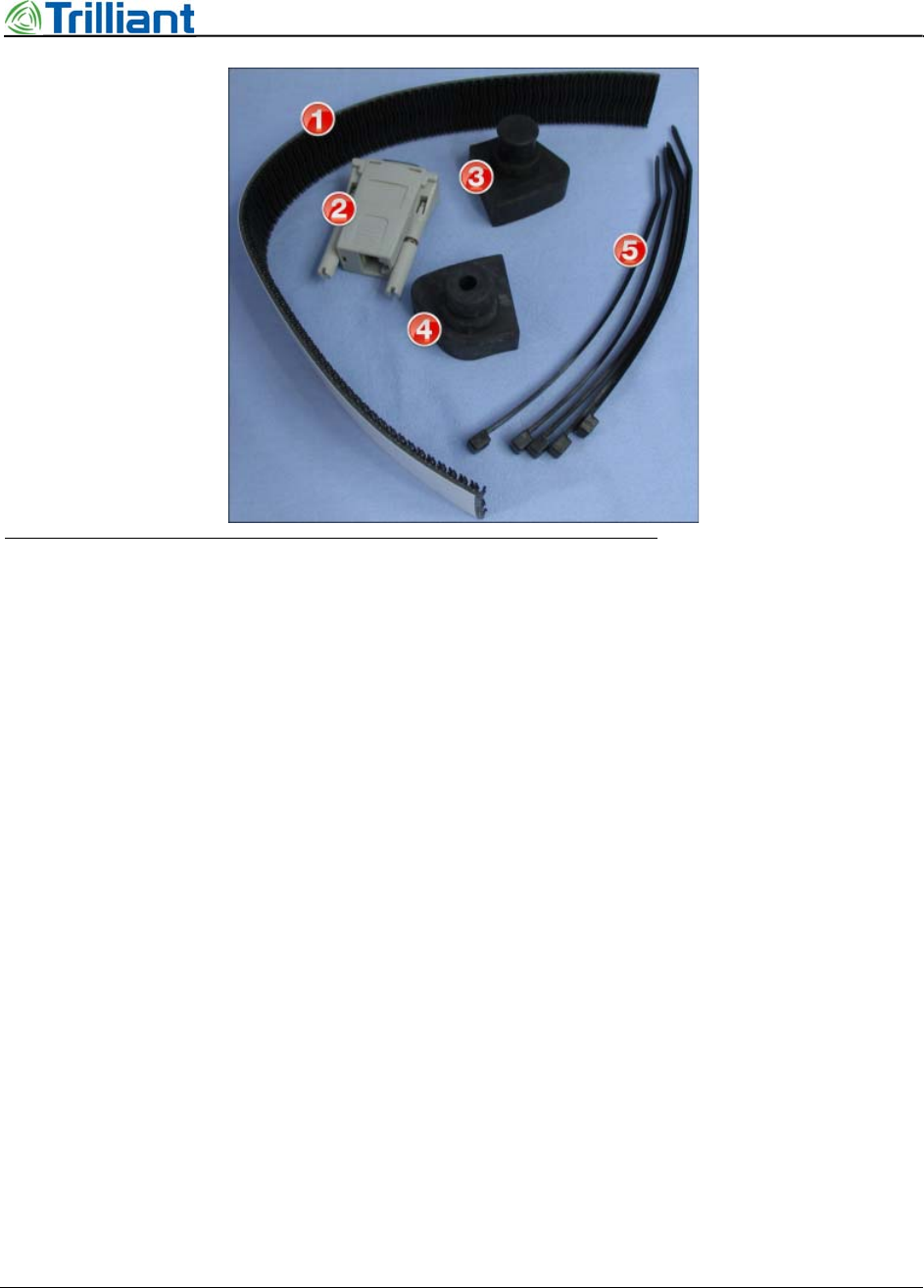
Figure 4 Accessory bag with miscellaneous parts
Miscellaneous parts:
1. Velcro strap
2. RJ-45 to DB-9 adapter
3. Interface door plug
4. Interface door cable seal; used with a serial cable
5. Tie wraps
16 SecureMesh Extender Bridge Installation Guide
NOTICE: The contents of this document are proprietary and confidential and the property of Trilliant Holdings, Inc.,
its subsidiaries, affiliates, and/or licensors. This document is provided subject to the confidentiality obligations set
forth in the agreement between your company and Trilliant. The contents may not be used or disclosed without the
express written consent of Trilliant.
Chapter 3 - Prepare for Installation
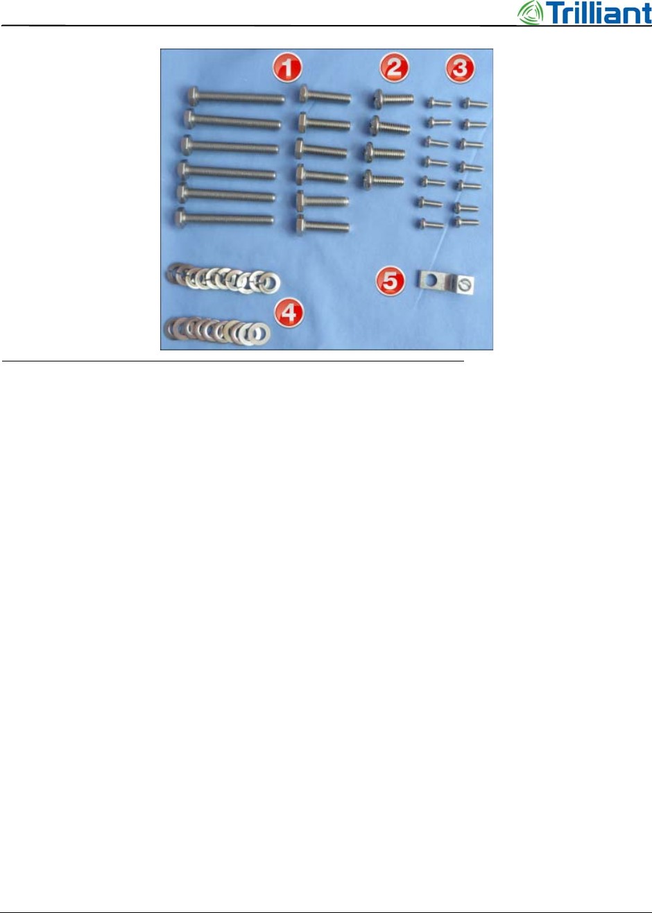
Figure 5 Accessory bag with screws, bolts, nuts and washers
Screws, bolts, nuts and washers:
1. 1/4-28 hex head bolts, 1 inch and 2 inch
2. 1/4-20 pan head screws, 0.75 inch
3. 6-32 pan head screws, 0.44 inch (seven are spares)
4. 1/4 inch lock washers and flat washers
5. Ground lug
Prepare the Extender Bridge
Follow the steps in this chapter to prepare the Extender Bridge and provision it. Complete the
steps in a lab or workshop before arriving at the permanent installation location.
1. Turn the Extender Bridge upside down to attach the clamp mount to the base of the
Extender Bridge (see Figure 6).
SecureMesh Extender Bridge Installation Guide 17
NOTICE: The contents of this document are proprietary and confidential and the property of Trilliant Holdings, Inc.,
its subsidiaries, affiliates, and/or licensors. This document is provided subject to the confidentiality obligations set
forth in the agreement between your company and Trilliant. The contents may not be used or disclosed without the
express written consent of Trilliant.
Prepare the Surge Suppressor
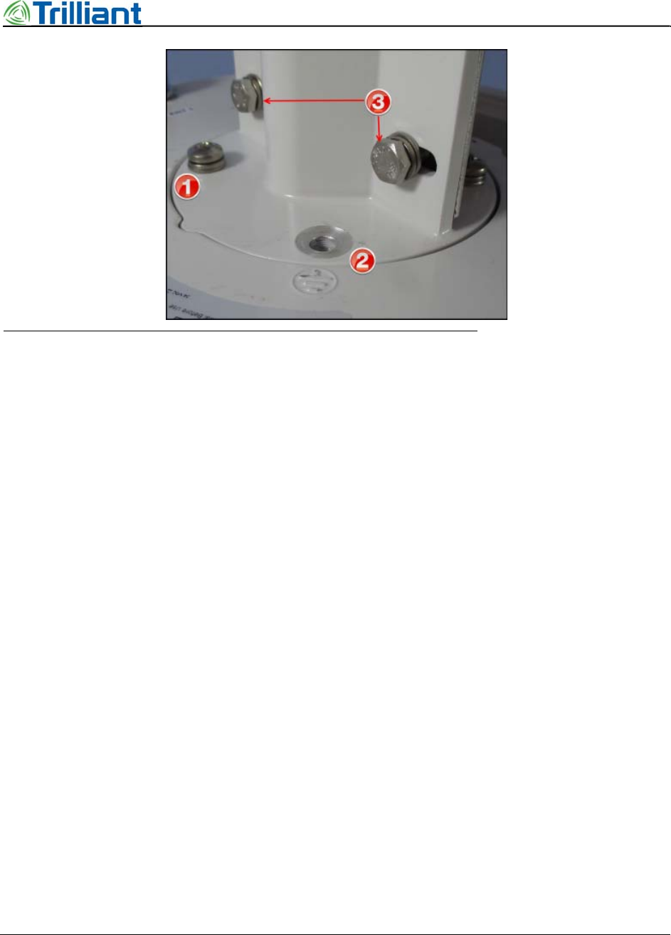
Figure 6 Clamp mount on Extender Bridge
2. Align the point on the clamp mount with the notch on the base of the Extender Bridge (see
#1 in Figure 6).
3. Attach the clamp to the base with three ¼-20 x 0.75 inch screws through a lock washer, a
flat washer, the clamp mount, and then into the base of the Extender Bridge at three
places; omit the screw and washers at the ground symbol (see #2 in Figure 6).
4. Place the clamp next to the clamp mount and align the six slots and threaded holes.
5. Insert a ¼-28 x 2 inch bolt through a lock washer to loosely attach the clamp to the clamp
mount at six places (see #3 in Figure 6).
6. Insert the mounting pole in the clamp mount.
7. Tighten the six screws (see Figure 6).
Prepare the Surge Suppressor
If the serial CONSOLE and/or ETHERNET ports will be used, Trilliant recommends that you
install a surge protector for each port.
To connect a surge suppressor device to the Extender Bridge, use a UV protected, Shielded (F/
UTP) CAT6 cable, where the shield is connected by drain wire to the connector. Steps to mount
the surge suppressor vary according to the following options.
•(Preferred) Citel Ethernet surge suppressor (see “Citel 521-R0655-01 Ethernet Surge
Suppressor” on page 18)
•(Alternate) AL-0248 Ethernet surge suppressor (see “L-Com AL-0248 Ethernet Surge
Suppressor” on page 21
•Serial surge suppressor (see “L-COM Serial Surge Suppressor” on page 24)
18 SecureMesh Extender Bridge Installation Guide
NOTICE: The contents of this document are proprietary and confidential and the property of Trilliant Holdings, Inc.,
its subsidiaries, affiliates, and/or licensors. This document is provided subject to the confidentiality obligations set
forth in the agreement between your company and Trilliant. The contents may not be used or disclosed without the
express written consent of Trilliant.
Chapter 3 - Prepare for Installation
Citel 521-R0655-01 Ethernet Surge Suppressor
The Citel surge suppressor includes one cable-seal gasket. One ground wire and two CAT 6 cables
are routed through the gasket. The 6 ft (1.8 m) cable plugs into the ETHERNET port on the
Extender Bridge. The other cable plugs into the PoE source.
1. Measure from the location where the Extender Bridge will be installed to the location of
the Power Service Unit (PSU), allow extra length for a service loop (depending on the
location), and obtain a CAT6 cable of the appropriate length.
Note: The maximum allowed cable length is 328 ft (100 m).
2. At the port on the surge protector, disassemble the gasket.
3. If a connector cover is present on the cable, remove it.
4. With a sharp tool such as an Exacto knife, make a small hole in the gasket on the surge
protector.
5. Route both CAT6 cables through the hole in the gasket.
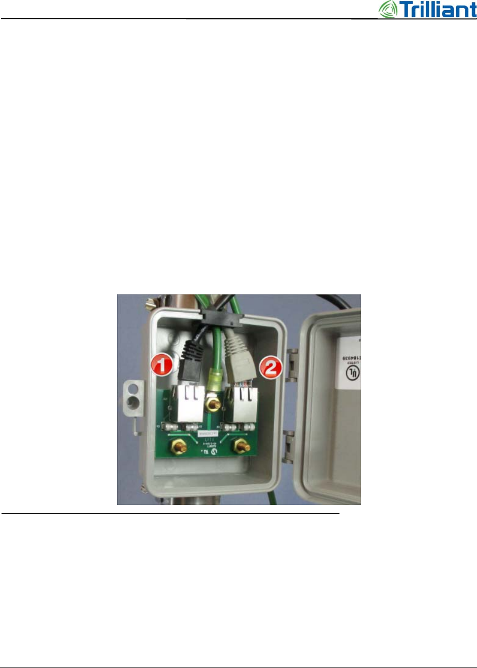
6. Plug the 6 ft (1.8 m) cable into JP2 (see #1 in Figure 7).
Figure 7 Citel surge suppressor with gasket and cables
7. Plug the other cable into JP1 (see #2 in Figure 7).
8. Use hose clamps to mount the surge suppressor on the pole, next to the Extender Bridge
(see Figure 8).
SecureMesh Extender Bridge Installation Guide 19
NOTICE: The contents of this document are proprietary and confidential and the property of Trilliant Holdings, Inc.,
its subsidiaries, affiliates, and/or licensors. This document is provided subject to the confidentiality obligations set
forth in the agreement between your company and Trilliant. The contents may not be used or disclosed without the
express written consent of Trilliant.
Prepare the Surge Suppressor
Figure 8 Hose clamps to mount Citel surge suppressor
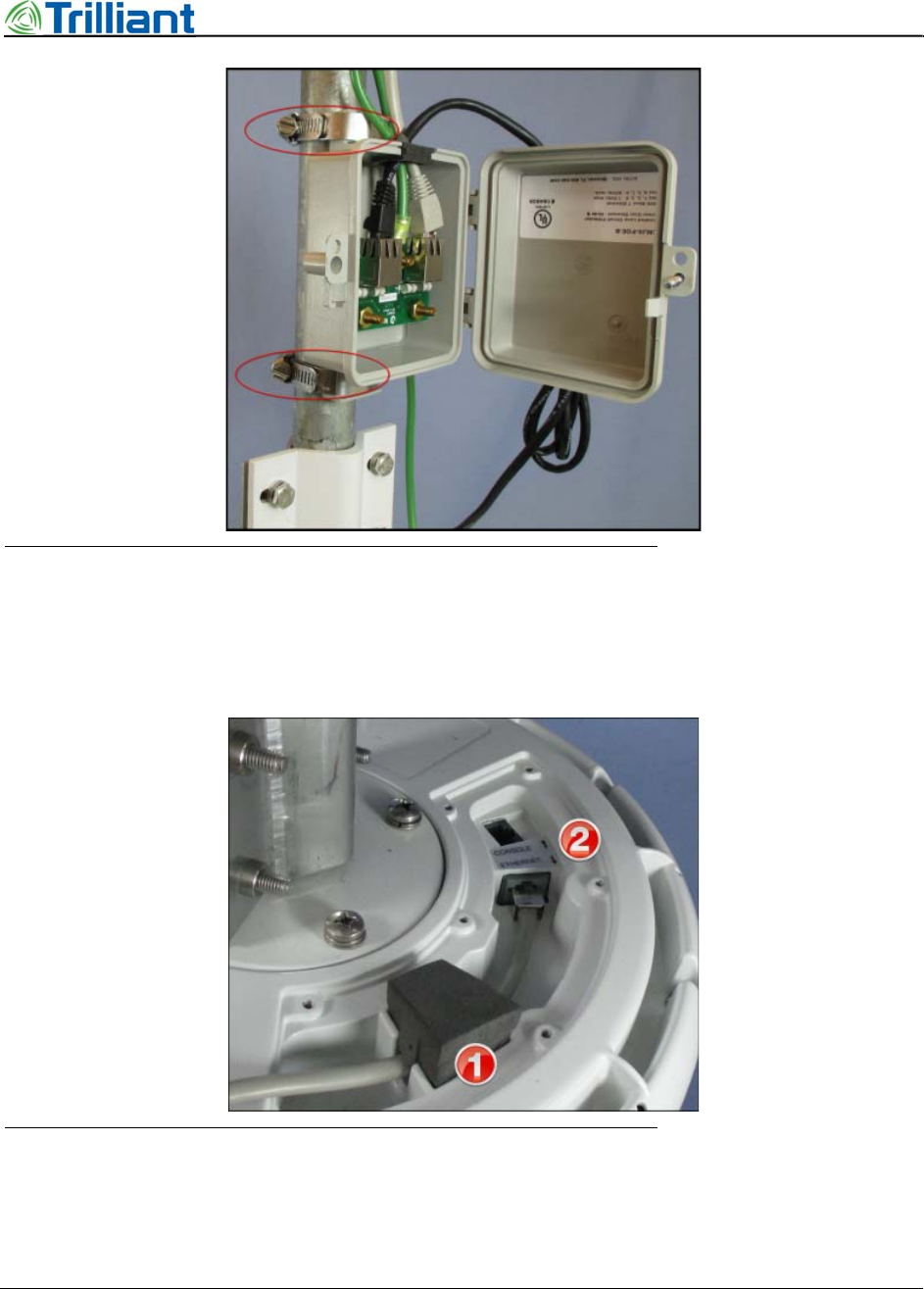
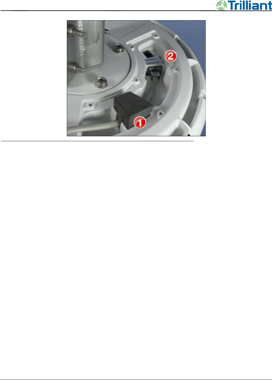
9. Route the 6 ft (1.8 m) Ethernet cable into the cavity in the base of the Extender Bridge,
through the foam gasket (see #1 in Figure 9), and then plug it into the ETHERNET port
(see #2 in Figure 9).
Figure 9 Ethernet cable in base
10. Bundle the excess cable length and secure it with tie wraps.
11. At the ground symbol on the base (see #2 in Figure 6), insert the ground screw through:
20 SecureMesh Extender Bridge Installation Guide
NOTICE: The contents of this document are proprietary and confidential and the property of Trilliant Holdings, Inc.,
its subsidiaries, affiliates, and/or licensors. This document is provided subject to the confidentiality obligations set
forth in the agreement between your company and Trilliant. The contents may not be used or disclosed without the
express written consent of Trilliant.
Chapter 3 - Prepare for Installation
a. the flat and lock washers
b. the lug on the green ground wire coming from the surge suppressor
c. the lug on the ground wire that extends to the site ground loop
d. the clamp mount
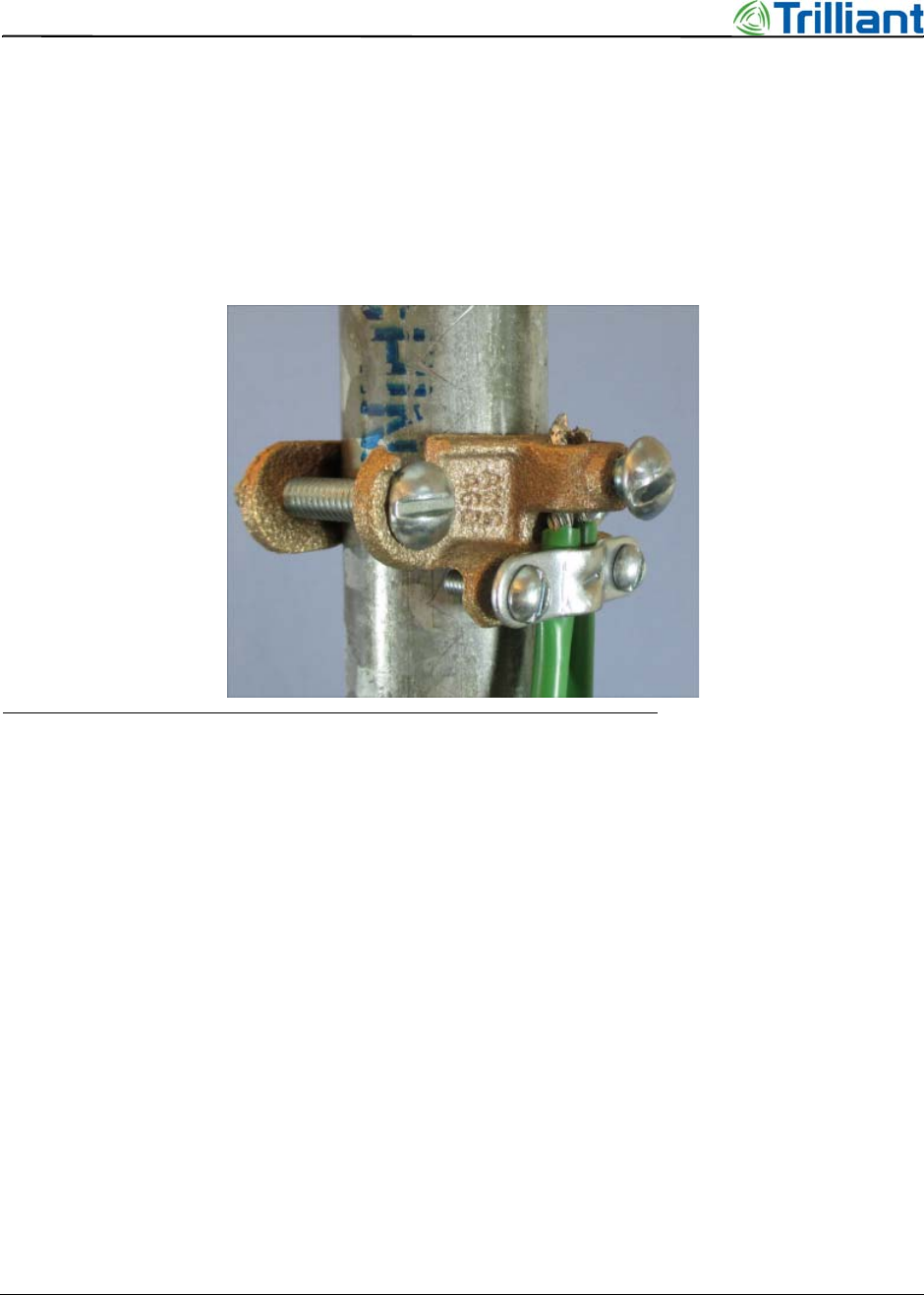
12. Turn the screw a few times so that it is attached, but still loose.
13. Mount a grounding clamp above the surge suppressor (see Figure 10).
Figure 10 Grounding clamp
14. Route the following ground wires into the grounding clamp:
•Ground wire from the base
•Ground wire from the surge suppressor
•Ground wire that will extend to the site ground point, if mounting on a non-conductive
utility pole; for guidelines for the site ground, see “Grounding Requirements” on
page 12
15. Secure the ground wires in the grounding clamp.
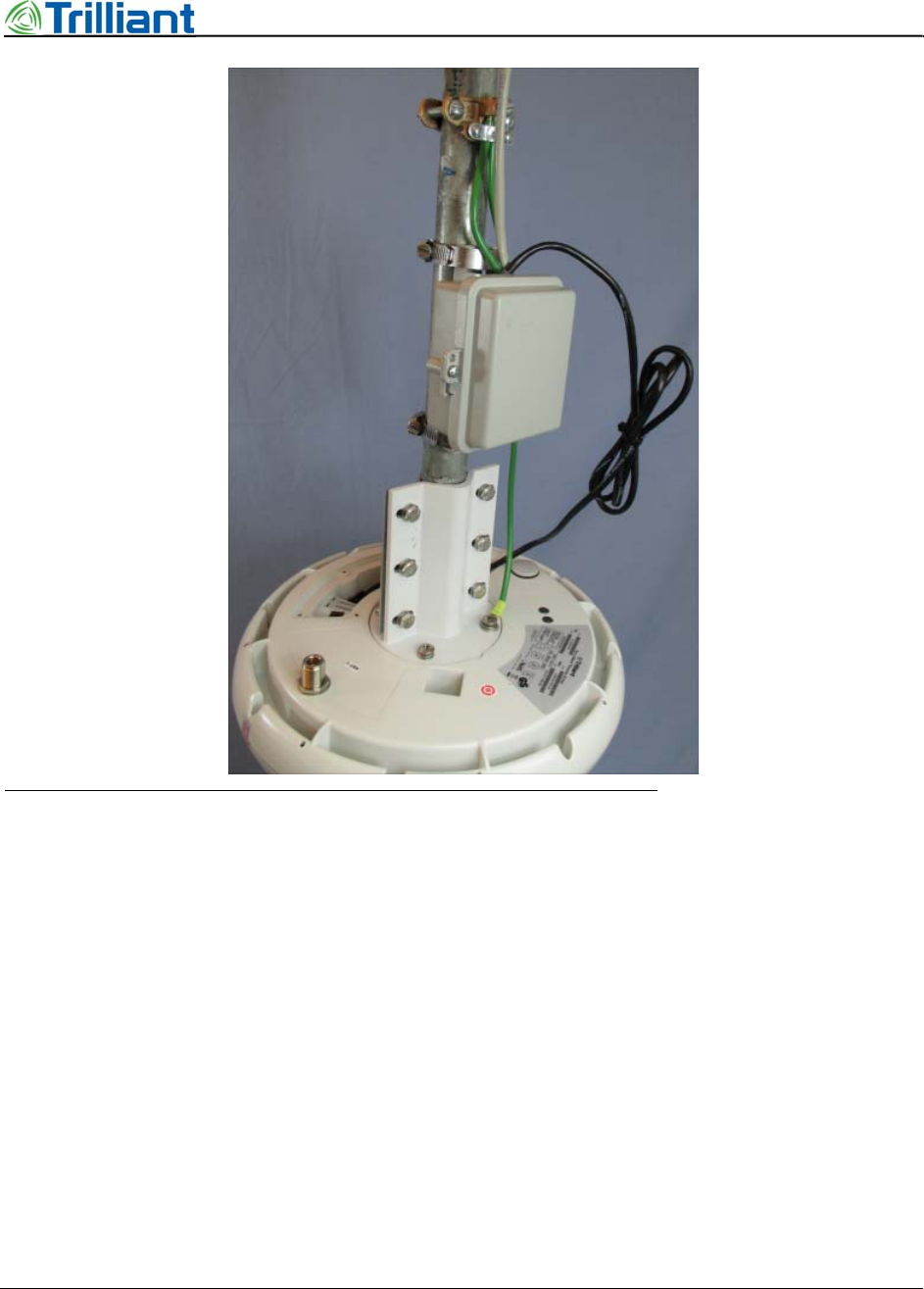
16. Secure the cover on the surge suppressor box.
Figure 11 shows a finished assembly.
SecureMesh Extender Bridge Installation Guide 21
NOTICE: The contents of this document are proprietary and confidential and the property of Trilliant Holdings, Inc.,
its subsidiaries, affiliates, and/or licensors. This document is provided subject to the confidentiality obligations set
forth in the agreement between your company and Trilliant. The contents may not be used or disclosed without the
express written consent of Trilliant.
Prepare the Surge Suppressor
Figure 11 Assembled and mounted Citel surge protector
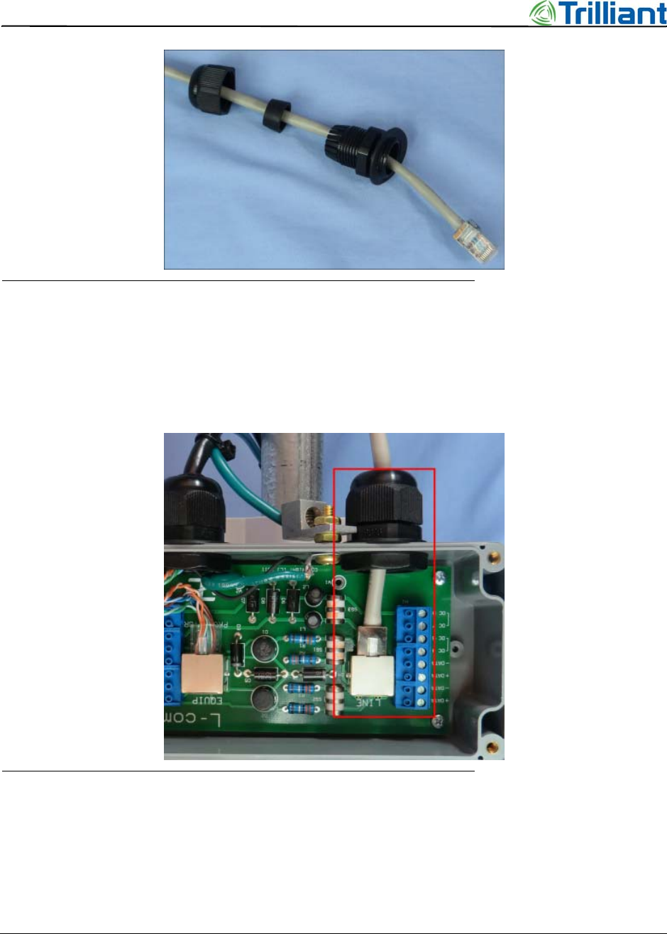
L-Com AL-0248 Ethernet Surge Suppressor
The AL-0248 surge suppressor includes two cable seal gaskets (glands) that are water-tight. The
CAT6 cable that plugs into the ETHERNET port on the Extender Bridge is pre-installed through
one gasket. Another outdoor CAT6 cable, which plugs into the PoE, must be routed through the
other gasket before the connector is attached.
1. Measure from the location where the Extender Bridge will be installed to the location of
the PSU, allow extra length for a service loop (depending on the location), and obtain a
CAT6 cable of the appropriate length.
Note: The maximum allowed cable length is 328 ft (100 m).
2. If a cover is present on the cable connector, remove it.
3. At the unused port on the surge protector, disassemble the gasket (see Figure 12).
22 SecureMesh Extender Bridge Installation Guide
NOTICE: The contents of this document are proprietary and confidential and the property of Trilliant Holdings, Inc.,
its subsidiaries, affiliates, and/or licensors. This document is provided subject to the confidentiality obligations set
forth in the agreement between your company and Trilliant. The contents may not be used or disclosed without the
express written consent of Trilliant.
Chapter 3 - Prepare for Installation
Figure 12 Disassembled gasket with CAT6 cable
4. Route the bare connector of the CAT6 cable through the external parts of the gasket (see
Figure 12).
5. Route the cable connector into the surge protector and plug it into the circuit card (see
Figure 13).
Figure 13 Assembled gasket and Cat6 cable
6. Tighten the gasket parts at the surge protector port (see Figure 13).
7. Loosen (but do not remove) the screw located on the Extender Bridge clamp mount at 90°
clockwise from the ground symbol (see #1 in Figure 6).
8. Slide the notched corner of the bracket under the washers on the loose screw (see #1 in
Figure 14).
SecureMesh Extender Bridge Installation Guide 23
NOTICE: The contents of this document are proprietary and confidential and the property of Trilliant Holdings, Inc.,
its subsidiaries, affiliates, and/or licensors. This document is provided subject to the confidentiality obligations set
forth in the agreement between your company and Trilliant. The contents may not be used or disclosed without the
express written consent of Trilliant.
Prepare the Surge Suppressor
Figure 14 Mounting bracket for L-com Ethernet surge suppressor
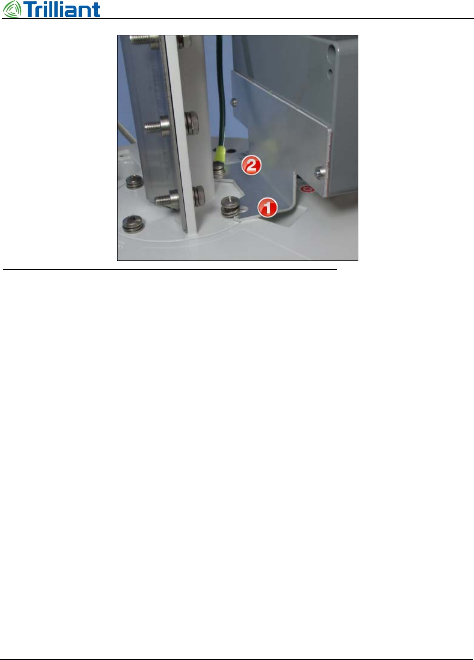
9. At the ground symbol on the base (see #2 in Figure 14), insert the ground screw through:
a. the flat and lock washers
b. the lug on the green ground wire coming from the surge suppressor
c. the lug on the ground wire that extends to the site ground loop
d. the hole in the surge suppressor bracket
e. the clamp mount
10. Turn the screw a few times so that it is attached, but still loose.
11. Tighten the screws at the clamp mount.
12. Secure the cover on the surge suppressor box.
13. Route the short CAT6 cable into the cavity in the base of the Extender Bridge, through the
foam gasket (see #1 in Figure 15), and plug it into the ETHERNET port (see #2 in
Figure 15).
24 SecureMesh Extender Bridge Installation Guide
NOTICE: The contents of this document are proprietary and confidential and the property of Trilliant Holdings, Inc.,
its subsidiaries, affiliates, and/or licensors. This document is provided subject to the confidentiality obligations set
forth in the agreement between your company and Trilliant. The contents may not be used or disclosed without the
express written consent of Trilliant.
Chapter 3 - Prepare for Installation
Figure 15 Ethernet cable for AL-0248 surge suppressor
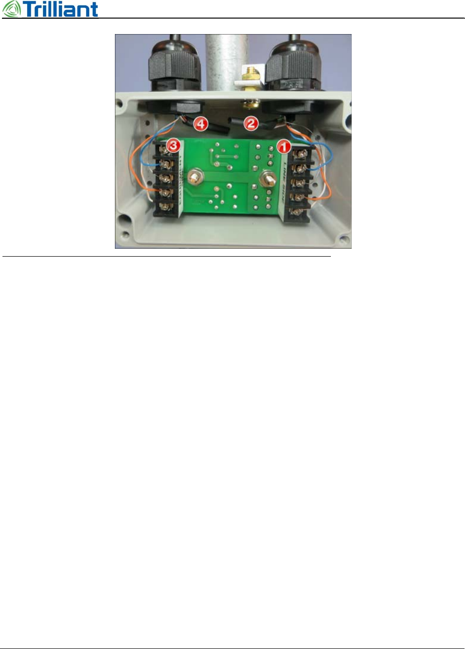
L-COM Serial Surge Suppressor
The L-Com serial surge suppressor includes two cable seal gaskets. The CAT6 cables must be
must be routed through the gaskets. The short cable is attached to the serial CONSOLE port on
the Extender Bridge. The long cable is attached to a serial port on a laptop or other equipment.
One ground wire must be attached to the terminal between the gaskets.
1. Measure from the location where the Extender Bridge will be installed to the location of
the terminal equipment, allow extra length for a service loop (depending on the location),
and obtain a CAT6 cable of the appropriate length (the long cable)
Note: The maximum allowed cable length is 328 ft (100 m).
2. If a connector is present on one end the long cable, remove it.
3. Loosen the outer nuts on both gaskets.
4. Route the bare end of the long cable through the gasket near the terminal block labeled
“LINE SIDE” (see #1 in Figure 16).
SecureMesh Extender Bridge Installation Guide 25
NOTICE: The contents of this document are proprietary and confidential and the property of Trilliant Holdings, Inc.,
its subsidiaries, affiliates, and/or licensors. This document is provided subject to the confidentiality obligations set
forth in the agreement between your company and Trilliant. The contents may not be used or disclosed without the
express written consent of Trilliant.
Prepare the Surge Suppressor
Figure 16 Serial Surge Suppressor Connections
5. Strip 1.5 inch (3.8 cm) of outer insulation from the CAT6 cable.
6. Identify the wires for the Ground, RxD, and TxD signals, and strip 0.2 inch (5.0 mm) of
insulation from them.
Note: The wire colors may not match those shown in Figure 16. If necessary, use an ohmmeter
to verify wires and signals.
7. At the LINE SIDE, attach the wires for the signals to the following screw posts, top to
bottom (see #1 in Figure 16):
•Ground: post 2
•Drain: post 3
•RxD: post 4
•TxD: post 5
8. Group the unused wires from the cable and wrap them with electrical tape or heat-shrink
tubing (see #2 in Figure 16) in order to prevent an electrical short.
9. Measure from the serial surge protector to the base of the Extender Bridge, and obtain a
CAT6 cable of the appropriate length (the “short” cable).
10. If a connector is present on one end of the short cable, remove it.
11. Route the bare end of the short cable through the gasket near the terminal block labeled
“EQUIPMENT SIDE” (see #3 in Figure 16.)
12. Strip 1.5 inch (3.8 mm) of outer insulation from the CAT6 cable.
26 SecureMesh Extender Bridge Installation Guide
NOTICE: The contents of this document are proprietary and confidential and the property of Trilliant Holdings, Inc.,
its subsidiaries, affiliates, and/or licensors. This document is provided subject to the confidentiality obligations set
forth in the agreement between your company and Trilliant. The contents may not be used or disclosed without the
express written consent of Trilliant.
Chapter 3 - Prepare for Installation
13. Identify the wires for the Ground, RxD, and TxD signals, and strip 0.2 inch (5.0 mm) of
insulation from them.
Note: The wire colors may not match those shown in Figure 16. If necessary, use an ohmmeter
to verify wires and signals.
14. At the EQUIPMENT SIDE, attach the wires to the following screw posts, top to bottom
(see #3 in Figure 16):
•Ground: post 2
•Drain: post 3
•RxD: post 4
•TxD: post 5
15. Group the unused wires from the cable and wrap them with electrical tape or heat-shrink
tubing (see #4 in Figure 16) in order to prevent an electrical short.
16. Tighten the outer nuts on both gaskets.
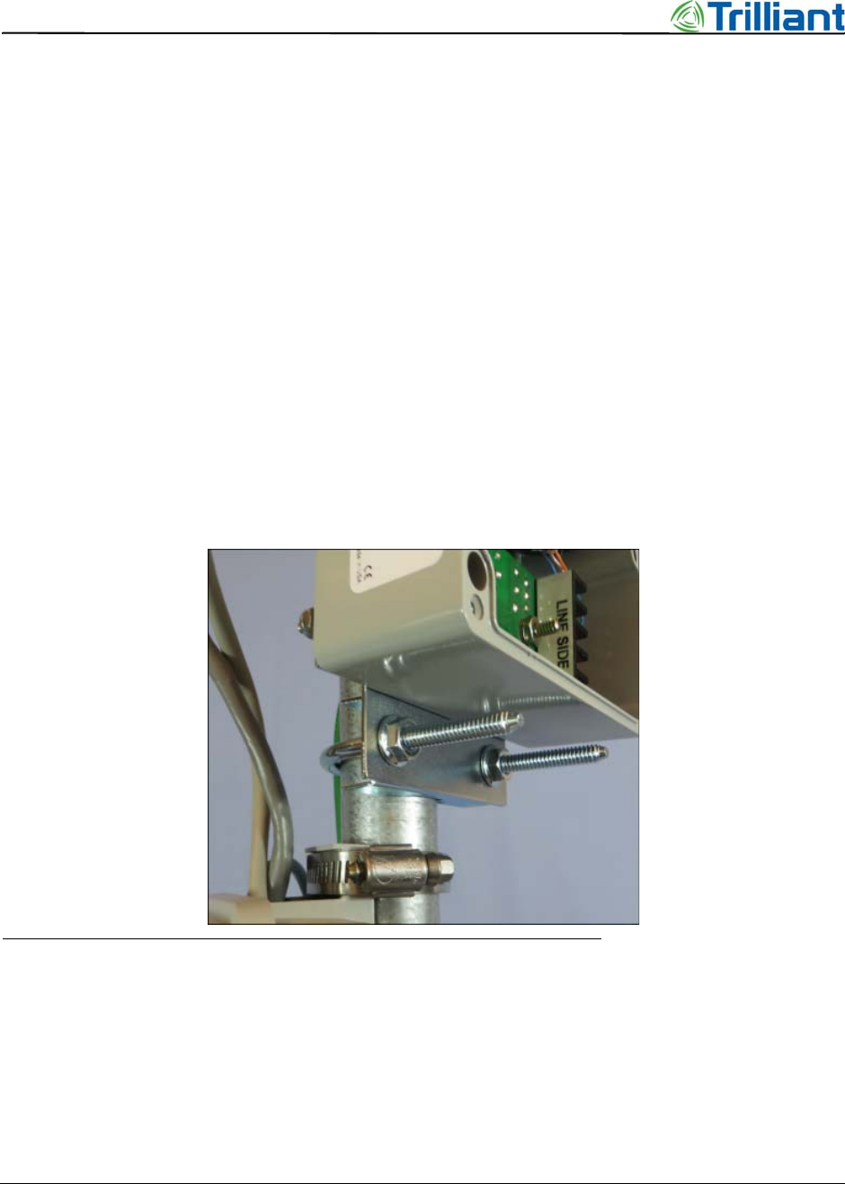
17. Use a U-bolt with lock washers and nuts to mount the surge suppressor on the pole,
adjacent to the Citel Ethernet surge suppressor, if present (see Figure 17).
Figure 17 L-com serial surge suppressor mounted with a U-bolt
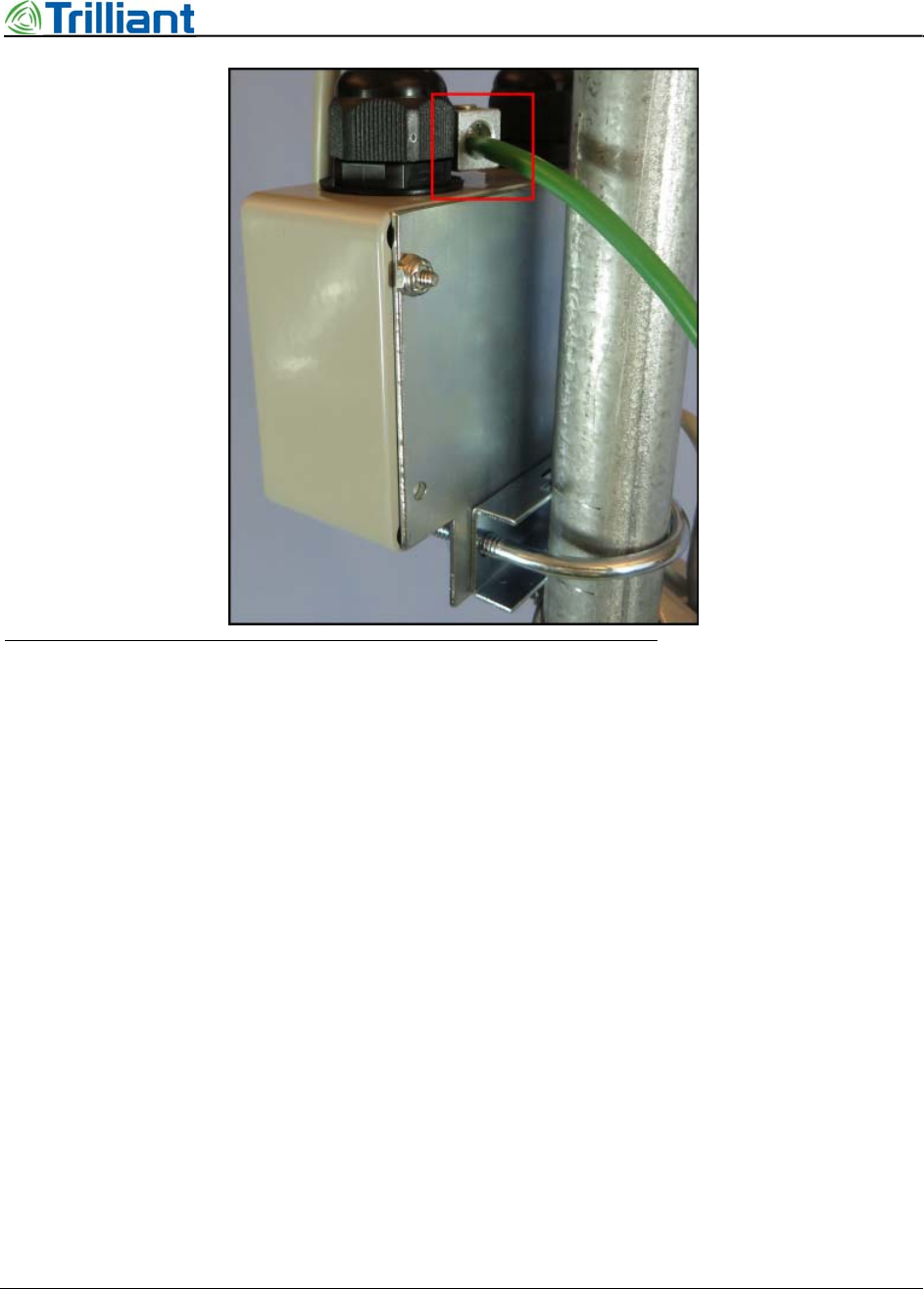
18. Measure from the ground lug located between the gaskets to the base of the Extender
Bridge, and obtain a 10 AWG ground wire of the appropriate length.
19. Attach the ground wire to the surge suppressor (see Figure 18).
SecureMesh Extender Bridge Installation Guide 27
NOTICE: The contents of this document are proprietary and confidential and the property of Trilliant Holdings, Inc.,
its subsidiaries, affiliates, and/or licensors. This document is provided subject to the confidentiality obligations set
forth in the agreement between your company and Trilliant. The contents may not be used or disclosed without the
express written consent of Trilliant.
Set Software Values
Figure 18 Ground wire on serial surge protector
20. At the ground symbol on the base (see #2 in Figure 6), insert the ground screw through:
a. the flat and lock washers
b. the lugs on the ground wires coming from both surge suppressors
c. the lug on the ground wire that extends to the site ground loop
d. the clamp mount
21. Tighten the ground screw.
22. Plug the short cable into the serial CONSOLE port in the base.
23. Secure the cover on the surge suppressor box.
Set Software Values
Each Extender Bridge is shipped from the factory with most utility-specific configuration items
already written into non-volatile memory. However, certain information must be configured prior
to installation. For details on parameters and setting the configuration, see the following
applications and manuals:
•Administrator Guide for SecureMesh WAN and NEMS
•Command Line Interface Reference
28 SecureMesh Extender Bridge Installation Guide
NOTICE: The contents of this document are proprietary and confidential and the property of Trilliant Holdings, Inc.,
its subsidiaries, affiliates, and/or licensors. This document is provided subject to the confidentiality obligations set
forth in the agreement between your company and Trilliant. The contents may not be used or disclosed without the
express written consent of Trilliant.
Chapter 3 - Prepare for Installation
•TstBench User Guide
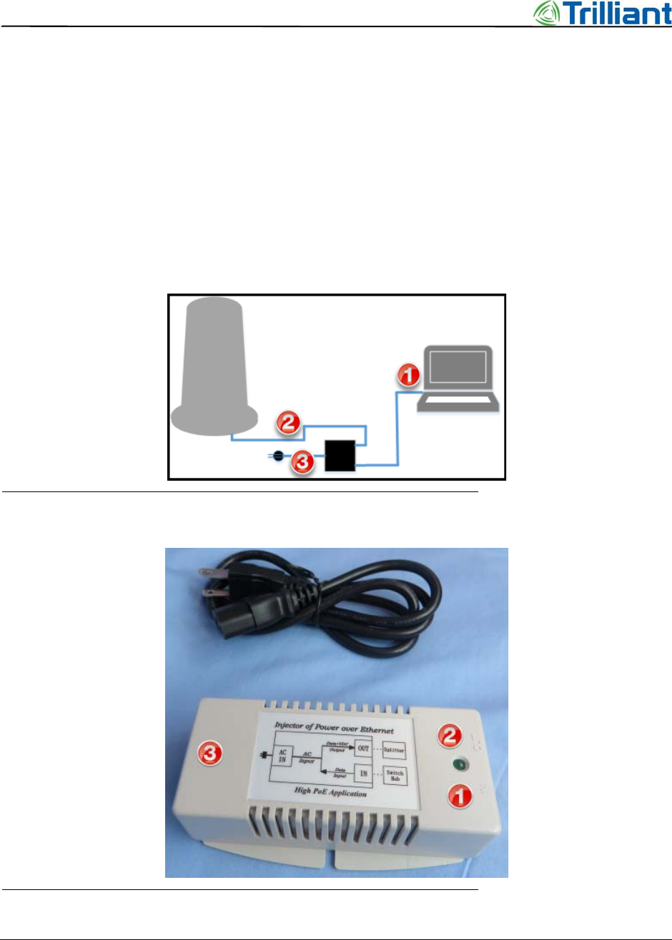
Provide power to the Extender Bridge, connect through the RS-232 serial Console, and then
configure parameters for both the Extender and Collector functions. See Figure 19 and Figure 20
and follow these steps:
1. Plug an Ethernet cable into the power injector (#1 in Figure 20) and the serial port on a
computer (#1 in Figure 19).
2. Plug an Ethernet cable into the power injector (#2 in Figure 20) and the ETHERNET port
on the Extender Bridge (#2 in Figure 19).
3. Plug the AC power cord into the power injector (#3 in Figure 20) and the wall socket (#3
in Figure 19).
Figure 19 Extender Bridge, power injector, and computer
Figure 20 Power over Ethernet detail

SecureMesh Extender Bridge Installation Guide 29
NOTICE: The contents of this document are proprietary and confidential and the property of Trilliant Holdings, Inc.,
its subsidiaries, affiliates, and/or licensors. This document is provided subject to the confidentiality obligations set
forth in the agreement between your company and Trilliant. The contents may not be used or disclosed without the
express written consent of Trilliant.
Set Software Values
Extender Parameters
1. To access the Extender functions, establish a Telnet session to IP address 192.168.0.2.
2. Use the command line interpreter (CLI) to set values for Extender parameters according to
your corporate standards and policy.
Note: Your company’s standards may include using a batch file to set values for the
parameters in order to prevent potential errors. If so, follow your company’s procedure.
The following parameters are typically required:
•Shared network key (netkey). The SecureMesh WAN uses the netkey to prove, by an
authentication handshake, that a node or device belongs to a specific network or operator.
The netkey is a string of 6 to 64 ASCII letters, numbers, and/or symbols.
Command: set netkey
•The VPN credentials, required for an IPsec VPN environment, include a shared secret
that allows a SecureMesh WAN management tunnel to be established to the VPN router.
All SecureMesh WAN nodes in a network must all use the same VPN shared secret. The
VPN shared secret is a string of up to 64 ASCII letters, numbers, and/or symbols.
Command: set prov vpnss
The following parameters are typically optional:
•The Country code, Region frequency, and Channel width values vary according to
the site and must match in order to ensure communication between devices.
Command: set prov freq; arguments: c, r, w
•The Primary frequency for the Extender Bridge should be the same as the center
frequency for the Gateway that the Extender Bridge will connect to.
Command: set prov freq; argument: p
•The Allowed frequencies set the range through which the Extender Bridge will “hunt” for
other SecureMesh WAN nodes and Gateways. Enter the frequency range as four-digit
numbers, such as “5745,” in MHz or as “all.”
Command: set prov freq; argument: a
•The IP address must be set manually if there is no DHCP server.
Command: set prov ip
Note: The Management VLAN runs on and is defined on the Gateway, not the Extender
Bridge.
Collector Parameters
1. To access the Collector functions, establish a TstBench session to IP address 192.168.0.3.
2. In TstBench, select Table ND05 74: SSH VPN Configuration, then set values for the
required and optional parameters according to your corporate standards and policy.
Typical parameters include the following:

30 SecureMesh Extender Bridge Installation Guide
NOTICE: The contents of this document are proprietary and confidential and the property of Trilliant Holdings, Inc.,
its subsidiaries, affiliates, and/or licensors. This document is provided subject to the confidentiality obligations set
forth in the agreement between your company and Trilliant. The contents may not be used or disclosed without the
express written consent of Trilliant.
Chapter 3 - Prepare for Installation
•The VPN credentials, required for an IPsec VPN environment, include a shared secret
that allows a SecureMesh NAN data tunnel to be established to the VPN router. The
VPN shared secret is a string of up to 64 ASCII letters, numbers, and/or symbols.
Note: In automatic provisioning mode, the IPsec VPN tunnel provides secure node
configuration. In order to establish the tunnel, the VPN credentials must be set before
deployment.
•Secure SHell is optional. Set the SSH username and password to ensure that only
authorized personnel can access the CLI. The username and password are ASCII strings
up to 32 bytes long.
SecureMesh Extender Bridge Installation Guide 31
NOTICE: The contents of this document are proprietary and confidential and the property of Trilliant Holdings, Inc.,
its subsidiaries, affiliates, and/or licensors. This document is provided subject to the confidentiality obligations set
forth in the agreement between your company and Trilliant. The contents may not be used or disclosed without the
express written consent of Trilliant.
4
Mount the Extender Bridge
This chapter describes the steps to mount the Extender Bridge on a pole or tower.
Attach the Extender Bridge to a utility pole or tower
Prepare the mounting location on the utility pole or tower, then mount the Extender Bridge.
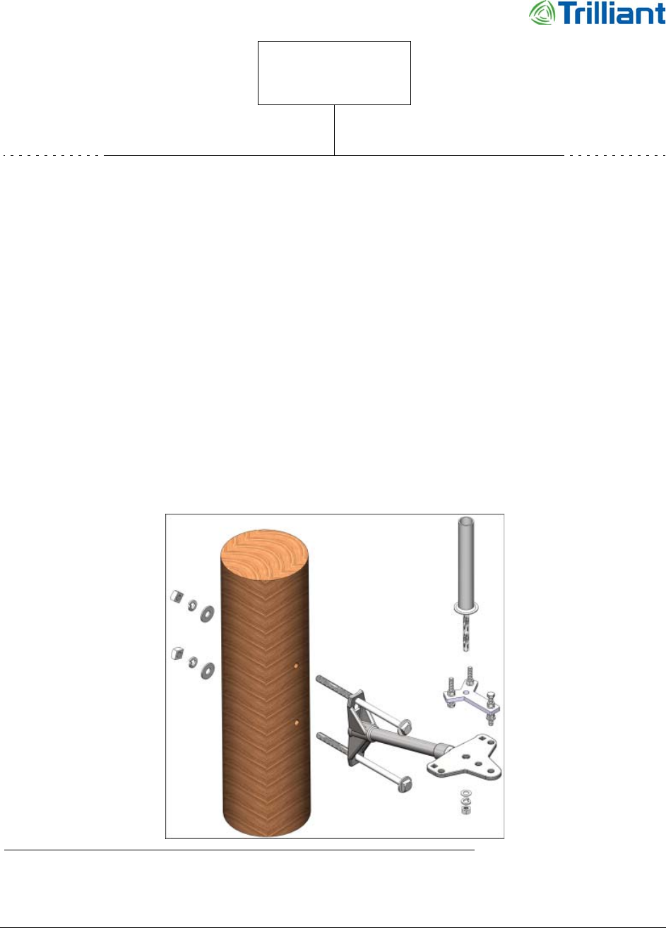
1. Mount the extension arm on the utility pole or tower with either bolts (see Figure 21) or
bands (for concrete poles). Follow the conventions for the site.
Figure 21 Typical hardware used to mount the Extender Bridge on a utility pole or tower
32 SecureMesh Extender Bridge Installation Guide
NOTICE: The contents of this document are proprietary and confidential and the property of Trilliant Holdings, Inc.,
its subsidiaries, affiliates, and/or licensors. This document is provided subject to the confidentiality obligations set
forth in the agreement between your company and Trilliant. The contents may not be used or disclosed without the
express written consent of Trilliant.
Chapter 4 - Mount the Extender Bridge
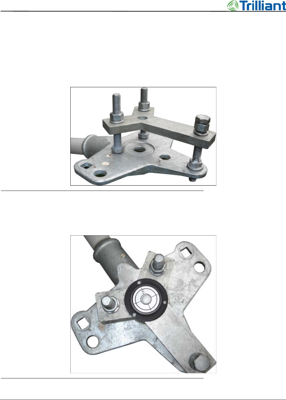
2. Place the Y-shaped, adjustable leveling bracket on the outer end of the extension arm (see
Figure 22).
•At the ends of the “Y,” place the heads of the bolts on the extension arm.
•Place the threaded end of the bolt with the solder nut through the outer-most hole in
the extension arm.
•Align the center holes for the mounting pole.
Figure 22 Leveling bracket on the extension arm
3. Place the magnetic level near the center hole on the adjustable leveling bracket (see
Figure 23).
Figure 23 Magnetic level on adjustable leveling bracket
SecureMesh Extender Bridge Installation Guide 33
NOTICE: The contents of this document are proprietary and confidential and the property of Trilliant Holdings, Inc.,
its subsidiaries, affiliates, and/or licensors. This document is provided subject to the confidentiality obligations set
forth in the agreement between your company and Trilliant. The contents may not be used or disclosed without the
express written consent of Trilliant.
Attach the Extender Bridge to a utility pole or tower
4. Adjust the three bolts until the bracket is level.
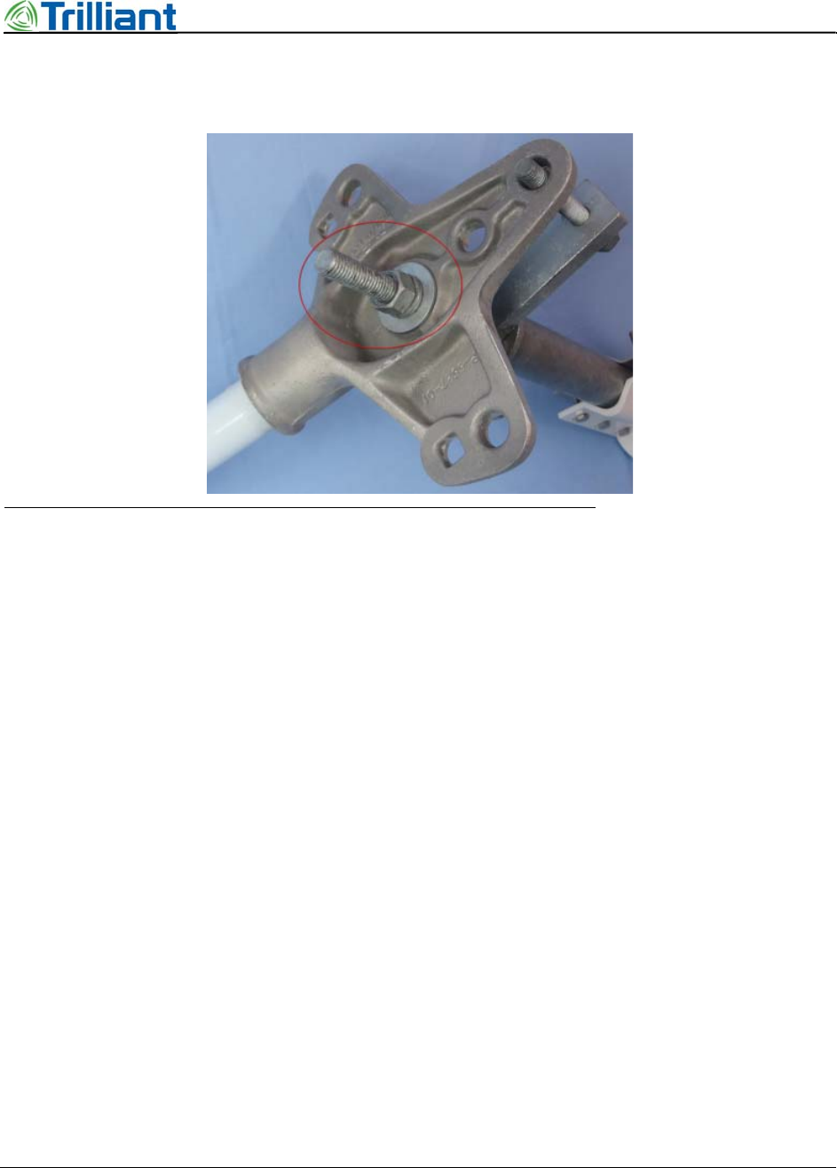
5. Place the Extender Bridge mounting pole through both center holes (Figure 24).
Figure 24 Nut and washers on mounting pole. extension arm, and leveling bracket
6. If needed, rotate the Extender Bridge to ensure that the NAN antenna will clear the
extension arm and nearby devices.
7. Secure the Extender Bridge mounting pole with washers and a nut (see Figure 24 and
Figure 25).
34 SecureMesh Extender Bridge Installation Guide
NOTICE: The contents of this document are proprietary and confidential and the property of Trilliant Holdings, Inc.,
its subsidiaries, affiliates, and/or licensors. This document is provided subject to the confidentiality obligations set
forth in the agreement between your company and Trilliant. The contents may not be used or disclosed without the
express written consent of Trilliant.
Chapter 4 - Mount the Extender Bridge
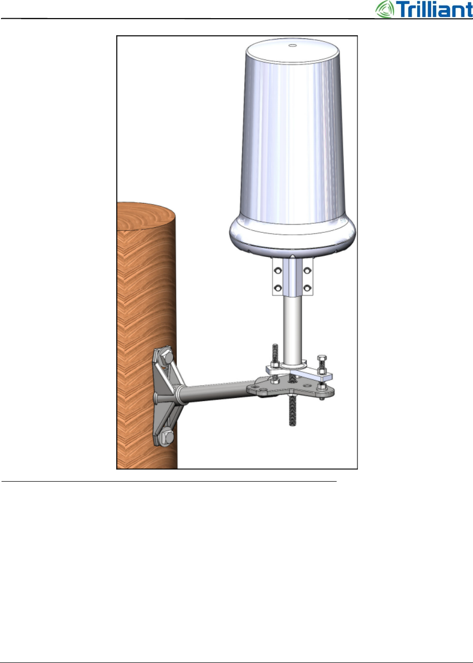
Figure 25 Typical installation: Extender Bridge mounted on utility pole
Attach the NAN Antenna
The NAN antenna enables communication with other devices in the neighborhood.
1. Remove the plastic cover from the N-type female connector at “ANT 1.”
2. To attach the antenna to the connector, grasp the antenna at the connector and tighten it to
not more than 1.1 lb-ft (1.5 N-m) (see Figure 26).
SecureMesh Extender Bridge Installation Guide 35
NOTICE: The contents of this document are proprietary and confidential and the property of Trilliant Holdings, Inc.,
its subsidiaries, affiliates, and/or licensors. This document is provided subject to the confidentiality obligations set
forth in the agreement between your company and Trilliant. The contents may not be used or disclosed without the
express written consent of Trilliant.
Attach the NAN Antenna
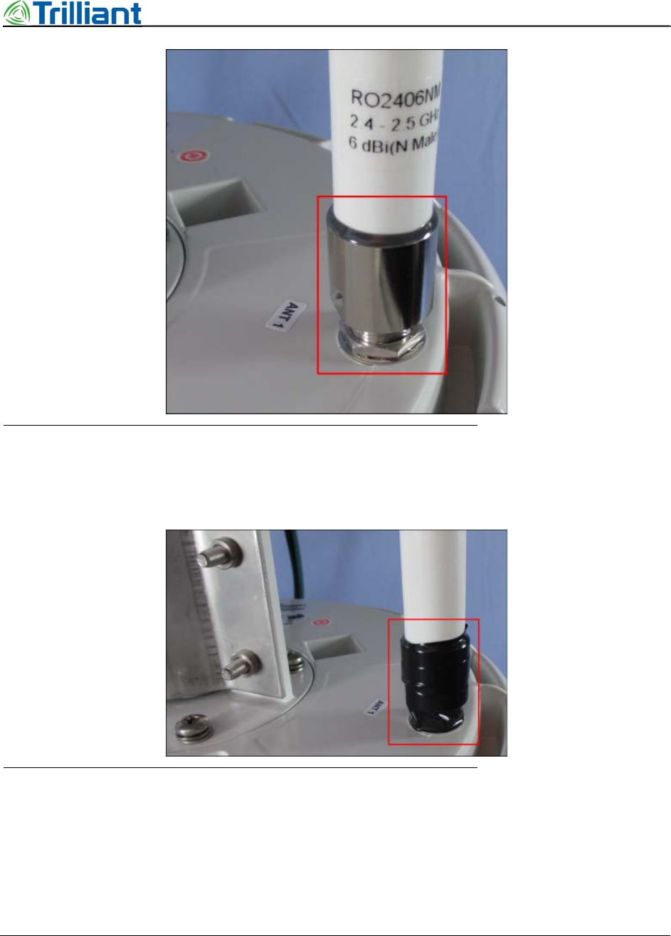
Figure 26 NAN Antenna mounted on base
3. Wrap the connector area with a single layer of electrical tape, about 6 in to 8 in (15 cm to
20 cm) long.
Figure 27 Inner layer of electrical tape on antenna connection
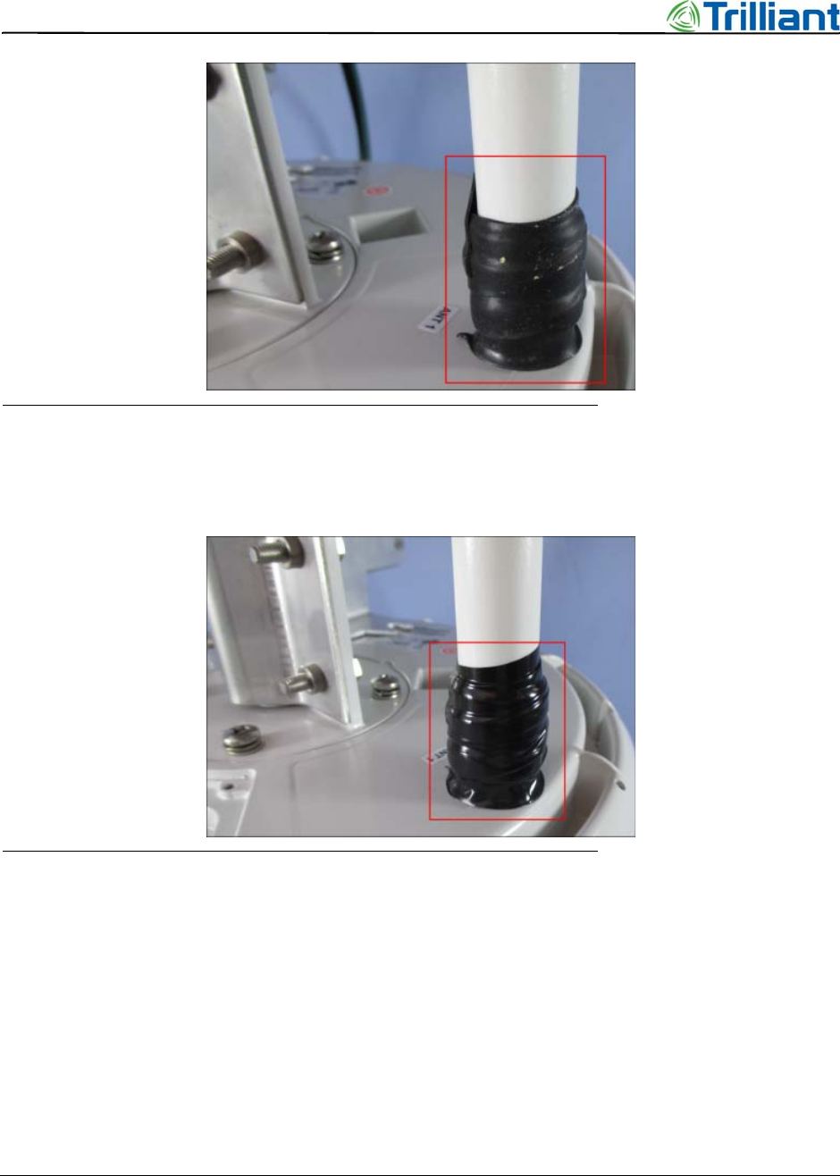
4. Cover the electrical tape with self-fusing rubber insulation, about 8 in to 10 in (20 cm to
25 cm) long, to seal and waterproof the connector.
36 SecureMesh Extender Bridge Installation Guide
NOTICE: The contents of this document are proprietary and confidential and the property of Trilliant Holdings, Inc.,
its subsidiaries, affiliates, and/or licensors. This document is provided subject to the confidentiality obligations set
forth in the agreement between your company and Trilliant. The contents may not be used or disclosed without the
express written consent of Trilliant.
Chapter 4 - Mount the Extender Bridge
Figure 28 Layer of rubber insulation on antenna connection
5. Cover the rubber insulation with electrical tape, about 10 in to 12 in (25 cm to 30 cm)
long, to prevent dust and dirt accumulating on the sticky rubber insulation.
Figure 29 Outer layer of tape on antenna connection
SecureMesh Extender Bridge Installation Guide 37
NOTICE: The contents of this document are proprietary and confidential and the property of Trilliant Holdings, Inc.,
its subsidiaries, affiliates, and/or licensors. This document is provided subject to the confidentiality obligations set
forth in the agreement between your company and Trilliant. The contents may not be used or disclosed without the
express written consent of Trilliant.
5
Commissioning the Extender
Bridge
This section provides the steps to connect power to the Extender Bridge and prepare it for normal
operation.
Power and Ground for the Extender Bridge
In order to start the Extender Bridge, it must have both ground and power.
1. One end of the ground wire is attached to the ground screw on the Extender Bridge base.
Attach the other end of the ground wire to the primary ground point.
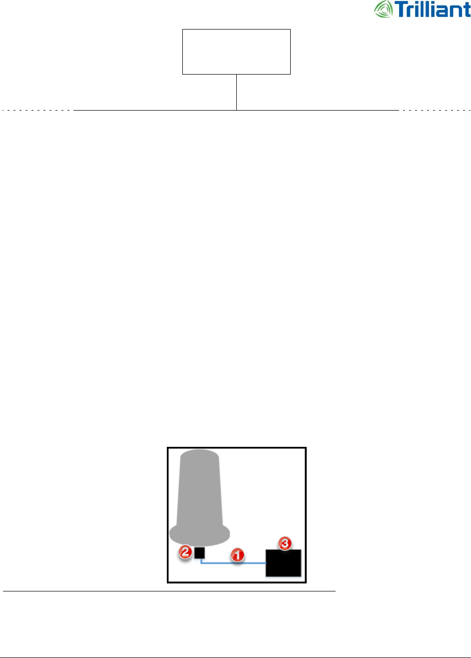
2. Route the PoE cable (see #1 in Figure 30) from the Ethernet surge suppressor (see #2 in
Figure 30) to the PSU (see #3 in Figure 30) and plug it into the WAN connector.
Note: For details about the PSU hardware, see the Installation Guide for the Secure Mesh
24V Power Service Unit.
Figure 30 Block diagram, PoE cable connections
3. Check all connections, including ground.
38 SecureMesh Extender Bridge Installation Guide
NOTICE: The contents of this document are proprietary and confidential and the property of Trilliant Holdings, Inc.,
its subsidiaries, affiliates, and/or licensors. This document is provided subject to the confidentiality obligations set
forth in the agreement between your company and Trilliant. The contents may not be used or disclosed without the
express written consent of Trilliant.
Chapter 5 - Commissioning the Extender Bridge
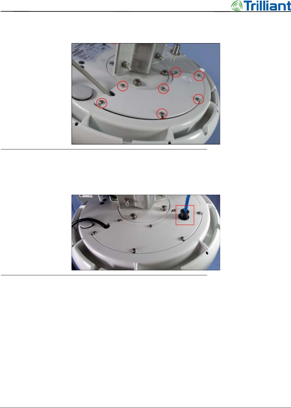
4. Replace the cover for the Ethernet connection on the base of the Extender Bridge. Tighten
the screws to 15 lb-ft (20 N-ms) of torque (see Figure 31).
Figure 31 Cover for Ethernet connection
Note: If the short CAT6 cable from the serial surge protector is plugged into the CONSOLE
port, route it through the cover and the cable seal (see Figure 32).
Figure 32 Cover and cable seal for serial surge suppressor cable
5. Use sturdy cable ties or Velcro wraps (this may require additional supplies) to secure all
the cables against strain, especially if the installation is subject to high winds.
6. Route the long CAT6 cable from the serial surge suppressor and plug it into customer
equipment.
Power-up Test
When the Extender Bridge receives power, the power-on sequence starts automatically. On the
base, the Link and Activity LEDs indicate the progress through the sequence.
In order to complete the power-on sequence and connect to the wireless network, the Extender
Bridge must have access to a GPS signal. The power-on sequence takes up to 15 minutes,

SecureMesh Extender Bridge Installation Guide 39
NOTICE: The contents of this document are proprietary and confidential and the property of Trilliant Holdings, Inc.,
its subsidiaries, affiliates, and/or licensors. This document is provided subject to the confidentiality obligations set
forth in the agreement between your company and Trilliant. The contents may not be used or disclosed without the
express written consent of Trilliant.
Power-up Test
depending on how quickly the device acquires the GPS signal and links to a parent device, such as
a Gateway.
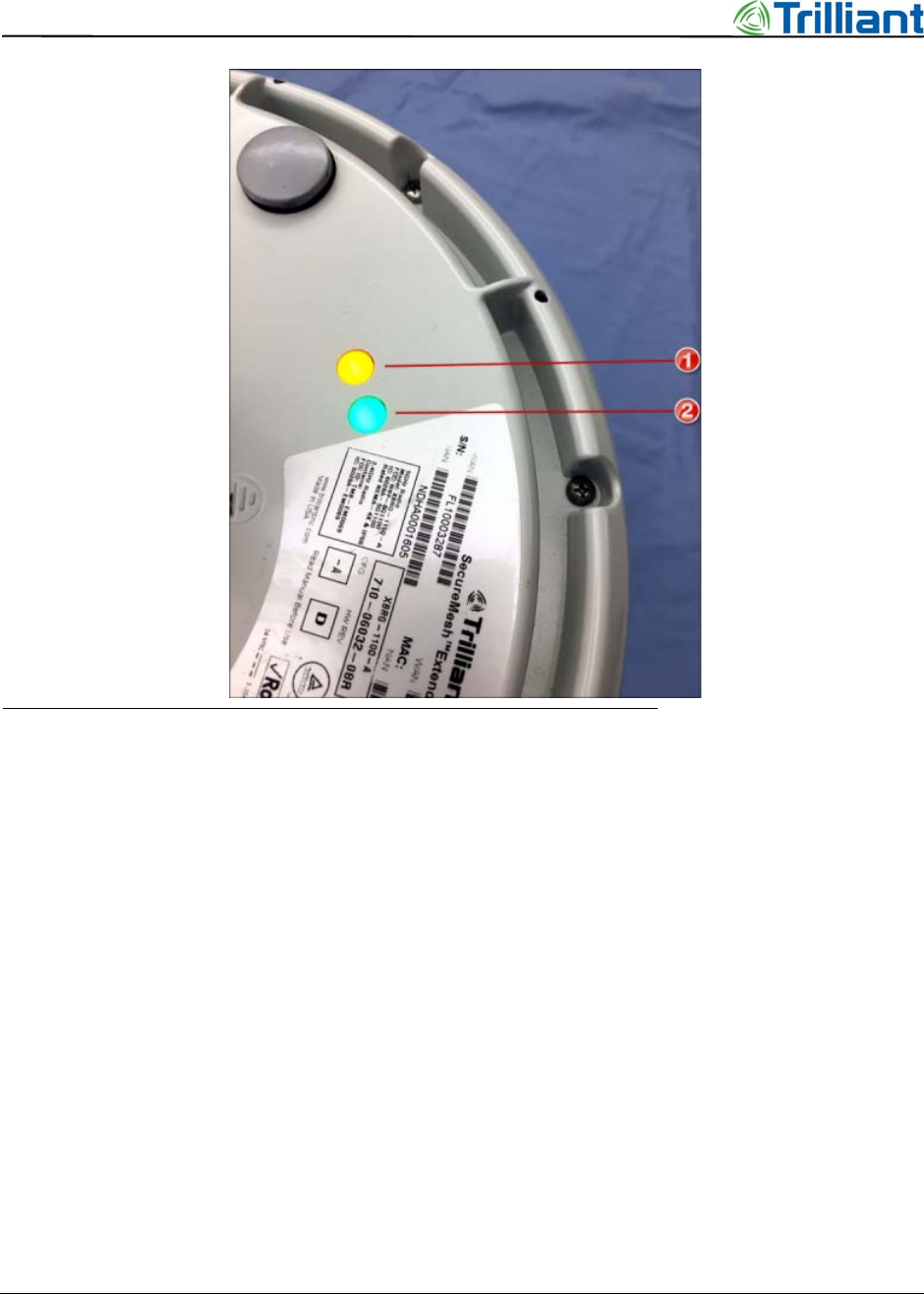
•When both LED lights are steady on, the Extender Bridge is successfully connected to the
wireless network and actively communicating. Table 2 provides details on the LEDs and
the device states. Figure 33 shows the LED location; #1 in the image is the Activity LED,
while #2 is the Link LED.
•If both LEDS immediately start to flash, you must configure the Extender Bridge for your
country location.
Note: For details about configuring the Extender Bridge for your country location, see the
Administrator Guide for SecureMesh WAN and NEMS.
Note: The startup sequence for the Link and Activity LEDs includes transient on, off, and
flash states.
Table 2 LEDs on the Extender Bridge
Activity (amber LED) Link (green LED) Device state
Off Off Power off
On Off Power on, in startup
Flash Flash Successful start: Linked to parent device; in standby mode
On On Successful start: Linked to parent device; in active mode
Off Steady flash Failure: Cannot link to a parent device
On, then to flash Off, then to flash Fault: Not configured for the specific country location
40 SecureMesh Extender Bridge Installation Guide
NOTICE: The contents of this document are proprietary and confidential and the property of Trilliant Holdings, Inc.,
its subsidiaries, affiliates, and/or licensors. This document is provided subject to the confidentiality obligations set
forth in the agreement between your company and Trilliant. The contents may not be used or disclosed without the
express written consent of Trilliant.
Chapter 5 - Commissioning the Extender Bridge
Figure 33 Link and Activity LEDs on base
Note: When power-up is complete, add RTV silicone to the Citel surge protector gasket for
additional weather protection.
Configuration and Startup
For details on how to automatically provision and then start the Extender Bridge, see the
Administrator Guide for SecureMesh WAN and NEMS.

SecureMesh Extender Bridge Installation Guide 41
NOTICE: The contents of this document are proprietary and confidential and the property of Trilliant Holdings, Inc.,
its subsidiaries, affiliates, and/or licensors. This document is provided subject to the confidentiality obligations set
forth in the agreement between your company and Trilliant. The contents may not be used or disclosed without the
express written consent of Trilliant.
6
Specifications and Pinouts
This section provides reference information for the Extender Bridge.
Specifications
When planning for installation, use the following specifications:
•Dimensions: 33.0 inch (83.8 cm) H x 12.2 in ch(31.0 cm) diameter
•Weight: 15.0 lb (6.8 kg)
Pinouts
Table 3 lists the signals and pins for an RJ-45 connector. Table 4 lists the signals and pins for the
adapter between the Extender Bridge Console port (RJ-45 connector) and a standard serial port
(DB-9 connector) on a computer.
Table 3 RJ-45 pins and/or signals
Pin Assignment
1 Ethernet data
2 Ethernet data
3 Ethernet data
4Power (+)
5Power (+)
6 Ethernet data
7Power (-)
8Power (-)

42 SecureMesh Extender Bridge Installation Guide
NOTICE: The contents of this document are proprietary and confidential and the property of Trilliant Holdings, Inc.,
its subsidiaries, affiliates, and/or licensors. This document is provided subject to the confidentiality obligations set
forth in the agreement between your company and Trilliant. The contents may not be used or disclosed without the
express written consent of Trilliant.
Chapter 6 - Specifications and Pinouts
Table 4 RJ-45 to DB-9 adapter pins and signals
RJ-45 (Extender Bridge
CONSOLE port) DB-9 (Computer serial port)
Signal Pin Pin Signal
TxD32RxD
Gnd45Gnd
RxD63TxD