Trilliant Networks CONN Wireless Mesh Wide Area Network CPE User Manual Installation Guide
Trilliant Networks, Inc. Wireless Mesh Wide Area Network CPE Installation Guide
Contents
- 1. Manual Appen B
- 2. Manual
- 3. Extender
- 4. Gateway
- 5. Extender Bridge
Extender Bridge
PL-0039A__1_1_Installation_Guide_SecureMesh_Extender_Bridge_rev1 PL-0039A
SecureMesh™ Extender Bridge
INSTALLATION GUIDE
SecureMeshTM Extender Bridge Installation Guide
Trilliant Incorporated page 2 of 26
Contents
INTRODUCTION ................................................................................................................................................................................ 4
SECUREMESH EXTENDER BRIDGE COMPONENTS ............................................................................................................................................... 5
ACCESSORIES ............................................................................................................................................................................................. 7
PREPARING FOR INSTALLATION ........................................................................................................................................................ 8
REQUIRED PRE-PROVISIONING EQUIPMENT ..................................................................................................................................................... 8
REQUIRED OUTDOOR EQUIPMENT ................................................................................................................................................................. 8
INSTALLATION LOCATION.............................................................................................................................................................................. 8
PRE-PROVISIONING ..................................................................................................................................................................................... 9
Extender Parameters ......................................................................................................................................................................... 9
Collector Parameters ....................................................................................................................................................................... 10
INSTALLING THE EXTENDER BRIDGE ............................................................................................................................................... 11
UTILITY POLE INSTALLATION ....................................................................................................................................................................... 12
Mounting the Device ....................................................................................................................................................................... 12
Grounding and Protecting the Device ............................................................................................................................................. 13
Attaching the NAN Antenna ............................................................................................................................................................ 14
Connecting the Device to a Source of Power ................................................................................................................................... 15
Completing the installation ............................................................................................................................................................. 16
STREETLIGHT POLE MOUNTING AND GROUNDING ........................................................................................................................................... 17
Mounting the Device ....................................................................................................................................................................... 17
Attaching the NAN Antenna ............................................................................................................................................................ 19
Connecting the Device to a Source of Power ................................................................................................................................... 20
Completing the Installation ............................................................................................................................................................. 21
COMMISSIONING THE EXTENDER BRIDGE ...................................................................................................................................... 22
CONFIGURING THE SECUREMESH EXTENDER BRIDGE ....................................................................................................................................... 22
MONITORING THE POWER-ON SEQUENCE ..................................................................................................................................................... 22
APPENDIX ....................................................................................................................................................................................... 23
GROUNDING GUIDELINES ........................................................................................................................................................................... 23
APPENDIX B .................................................................................................................................................................................... 25
REGULATORY INFORMATION ....................................................................................................................................................................... 25
SecureMeshTM Extender Bridge Installation Guide
Trilliant Incorporated page 3 of 26
SAFETY INFORMATION
Hazard Warning!
High Voltage. This situation or condition can cause injury due to electric shock.
Warnung!
Lesen und befolgen Sie die Warnhinweise und Anweisungen, die auf dem Produkt angebracht oder in der
Dokumentation enthalten sind.
Warning!
Read and follow all warning notices and instructions marked on the product or included in the
documentation.
Warnung!
Lesen und befolgen Sie die Warnhinweise und Anweisungen, die auf dem Produkt angebracht oder in der
Dokumentation enthalten sind.
Warning!
Only use attachments and accessories specified and/or sold by the manufacturer.
Warnung!
Verwenden Sie nur Zusatzgeräte und Zubehör angegeben und / oder verkauft wurde durch den Hersteller.
Warning!
Refer all servicing to qualified service personnel. Servicing is required when the device has been damaged
in any way, such as power-supply cord or plug is damaged, liquid has been spilled or objects have fallen into
the device, the device has been exposed to rain or moisture, does not operate normally, or has been
dropped.
Warnung!
Das Gerät sollte nur von qualifizierten Fachkräften gewartet werden. Eine Wartung ist fällig, wenn das Gerät
in irgendeiner Weise beschädigt wurde, wie bei beschädigtem Netzkabel oder Netzstecker, falls
Flüssigkeiten oder Objekte in das Gerät gelangen, das Gerät Regen oder Feuchtigkeit ausgesetzt wurde,
nicht ordnungsgemäß funktioniert oder fallen gelassen wurde.
Warning!
Do not open the chassis. There are no user-serviceable parts inside. Opening the chassis will void the
warranty unless performed by an Trilliant service center or licensed facility.
Warnung!
Öffnen Sie das Gehäuse nicht. Keine der Geräteteile können vom Benutzer gewartet werden. Durch das
Öffnen des Gehäuses wird die Garantie hinfällig, es sei denn, solche Wartungsarbeiten werden in einem
Trilliant-Service-Center oder einem lizenzierten Betrieb vorgenommen.
SecureMeshTM Extender Bridge Installation Guide
Trilliant Incorporated page 4 of 26
INTRODUCTION
The SecureMesh™ Extender Bridge combines the functionality of a SecureMesh Wide Area Network (WAN)
relay node and a SecureMesh Neighborhood Area Network (NAN) access point to create an integrated
product.
Each SecureMesh Extender Bridge employs a 5 GHz SecureMesh WAN radio with an array of 8 directional
antennas to interoperate as an element of the SecureMesh WAN and a 2.4 GHz SecureMesh NAN radio with
an omnidirectional dipole antenna to act as an access point for SecureMesh NAN devices. The Extender
Bridge uses the same enclosure as an Extender to house the WAN antenna array, the WAN Extender circuitry,
and optional 802.11b/g 2.4 GHz Wi-Fi access point circuitry as well as the NAN Collector circuitry.
Extender Functionality
The Extender Bridge’s 5 GHz SecureMesh WAN radio uses its array of eight, beam-switched, directional
antennas to provide extended range and full 360° coverage and acts as a relay node within the SecureMesh
WAN network.
The Extender Bridge offers an Ethernet port for WAN client devices, allowing a single client device or, by using
an external IP router or Ethernet switch, many client devices to connect to the WAN. If deployed using a
SecureMesh Power Service Unit (PSU), the Ethernet port for WAN client devices is made available through the
PSU’s port.
Collector Functionality
The Extender Bridge provides the functionality of a 2.4 GHz SecureMesh NAN Collector, supporting
SecureMesh electric meters, gas meters, load control switches, and other SecureMesh NAN devices to create
a wireless mesh subnetwork of the SecureMesh Neighborhood Area Network. The Extender Bridge
establishes time synchronization and coordinates overall operation of the NAN subnetwork defined by its
associated nodes and then routes NAN traffic to/from the UnitySuite Head-End Software via the SecureMesh
WAN.
SecureMeshTM Extender Bridge Installation Guide
Trilliant Incorporated page 5 of 26
SecureMesh Extender Bridge Components
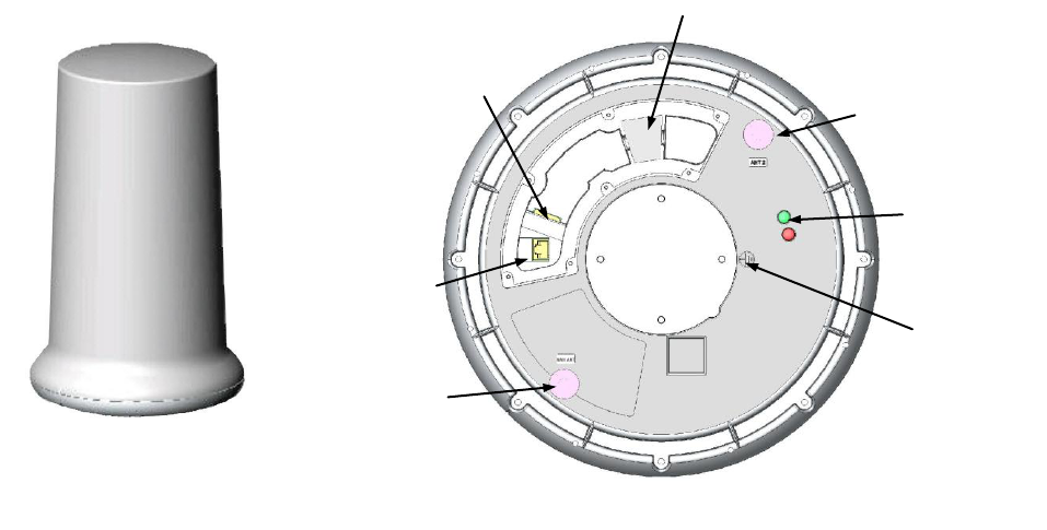
The following diagram shows the major components of the SecureMesh Extender Bridge.
side view
Ethernet, 8P8C
data and power
serial, 8P8C
NAN
antenna bulkhead
connector
water intrusion gasket
status lights
optional: Wi-Fi
access point bulkhead
connector
bottom view
grounding lug
SecureMeshTM Extender Bridge Installation Guide
Trilliant Incorporated page 6 of 26
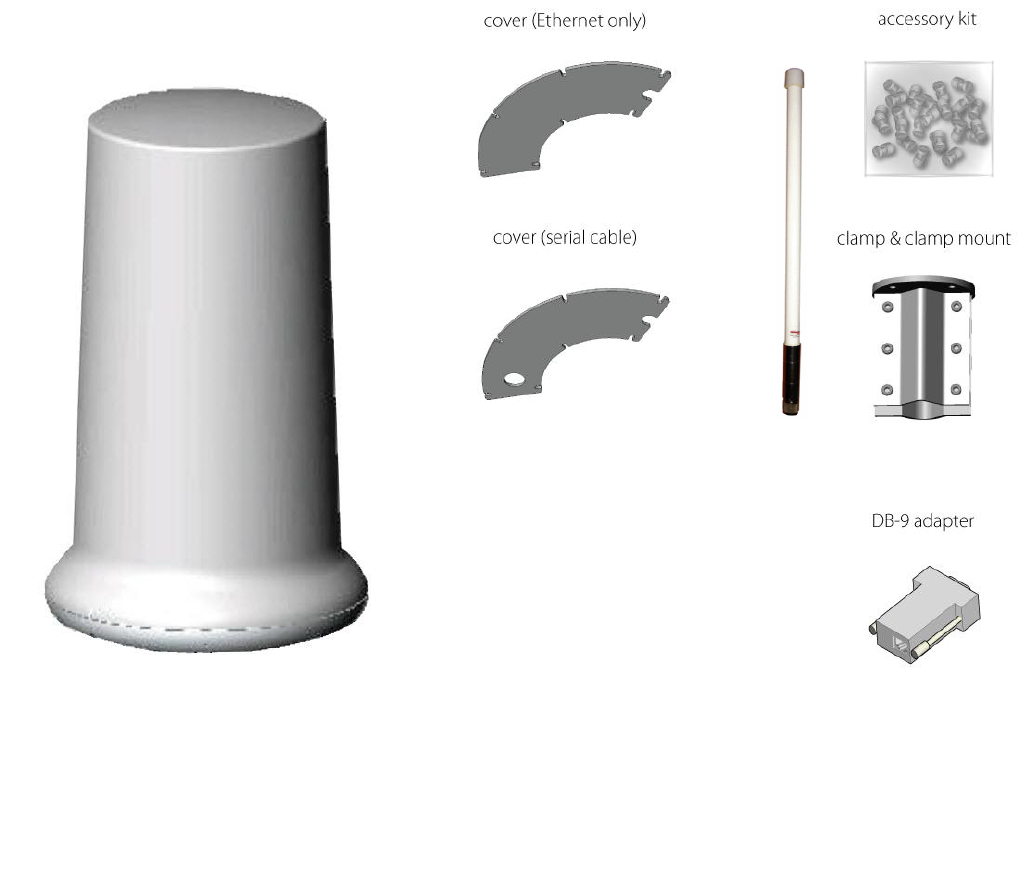
The following diagram shows the SecureMesh Extender Bridge package contents.
NAN antenna
SecureMesh Extender Bridge
SecureMeshTM Extender Bridge Installation Guide
Trilliant Incorporated page 7 of 26
Accessories
product number
description
Surge Suppressor
620-00705-01
required unless provided by customer
Horizontal
Pole Mounting Bracket
620-R0007-01
for horizontal pole mounting only (e.g., streetlight cantilevers)
Vertical
Pole Mounting Bracket
DK-0029A
for vertical pole mounting only (e.g., utility poles)
One of the following power supplies is required:
24V Power Service Unit
PSU-1024-33
recommended outdoor power supply and backup battery
24V PoE connection to SecureMesh Extender Bridge
Standard 802.3at 48V PoE connection to client device
(without battery backup)
33 Amp-hour backup battery (>8 hours backup at 68ºF /
20ºC)
not needed if site location provides an Uninterruptible Power
Supply
Indoor Power Supply
w/ PoE Injector
170-R0006-01
optional indoor power supply
100-240 VAC, 24 VDC, 1.3A
power cord sold separately (see below)
Streetlight
Power Supply
optional outdoor power supply
no battery backup capability
620-R0005-01
20-foot / 6-meter cable to photoelectric tap
620-R0005-02
3-foot / 1-meter cable to photoelectric tap
Streetlight
Installation Kit –
including Power Supply
optional horizontal pole installation kit
includes mounting bracket, streetlight power supply, and surge suppressor
620-00708-01
horizontal pole mount with 20-foot / 6-meter cable to
photoelectric tap
620-00708-02
horizontal pole mount with 3-foot / 1-meter cable to
photoelectric tap
Power Cord
to be purchased for use with Indoor Power Supply w/ PoE Injector
171-R0005-01
IEC320-C13 plug for Americas
171-R0005-02
IEC320-C13 plug for UK
171-R0005-03
IEC320-C13 plug for Europe
171-R0005-05
IEC320-C13 plug for Australia
171-R0005-06
IEC320-C13 plug for Latin America
SecureMeshTM Extender Bridge Installation Guide
Trilliant Incorporated page 8 of 26
PREPARING FOR INSTALLATION
Required Pre-Provisioning Equipment
The following equipment is required to support pre-provisioning of the Extender Bridge, typically in a lab
environment:
A PC with Trilliant’s TstBench software installed and connected to the same Ethernet network as the
SecureMesh Extender Bridge. The Extender Bridge’s default IP address for Extender functionality is
192.168.0.2; the default IP address for Collector functionality is 192.168.0.3.
A power supply, typically one of the power supplies listed as an Extender Bridge accessory.
A CAT5e, Ethernet cable for connecting the Extender Bridge’s Surge Protector to a 24V PoE power
supply and the site’s Ethernet network
Required Outdoor Equipment
The following equipment is required to support field installation of the Extender Bridge:
A power supply, typically one of the power supplies listed as an Extender Bridge accessory. For all
outdoor installations, the PSU-1024-33 SecureMesh Power Service Unit is recommended unless an
Uninterruptible Power Supply is available.
A CAT5e, UV-protected, Shielded-Twisted Pair (STP) Ethernet cable with ground wire for connecting
the Extender Bridge’s Surge Protector to the PoE power supply.
One of the accessory mounting brackets listed above or a similar mounting bracket providing a vertical
pole with a 1.25‖ to 2‖ diameter that is a minimum of 18‖ from any structure to the side of the Extender
Bridge. The vertical pole must extend a minimum of 5‖ above the horizontal surface of the bracket.
A 10 AWG (or larger) ground wire of sufficient length to connect the Extender Bridge to the primary
grounding point of the utility structure to which the Extender Bridge will be mounted.
A magnetic level to ensure the Extender Bridge is plumb.
Self-fusing rubber insulation and sealing tape such as Scotch® 130C or 2228 Rubber Mastic Tape
Installation Location
In general, a SecureMesh Extender Bridge should be installed in a location that will not obstruct the radio
signals to and from the SecureMesh Extender Bridge. The SecureMesh Extender Bridge should be installed in
a location that meets all of the following guidelines:
Installation and wiring of the SecureMesh Extender Bridge must conform to all local electrical codes
and ordinances.
The installation location must be either owned by the utility or the utility must have access rights to the
location.
The installation location must be able to provide adequate power. Note that the 24V Power Service
Unit requires 90-265 VAC 50/60 Hz power.
SecureMeshTM Extender Bridge Installation Guide
Trilliant Incorporated page 9 of 26
The Extender Bridge enclosure must be mounted at least 18 feet (5.5 meters) above ground level,
although radio performance and coverage will generally improve as the mounting height is increased.
The installation location must not obstruct radio communications. For example:
— The mounting structure should not block radio coverage or be adjacent to structures that block
radio coverage).
— The installation location must be clear of thick trees or brush growth upon installation and in the
foreseeable future. Foliage in the line of sight with other communicating devices can
detrimentally affect radio performance.
— The Extender Bridge should have an unobstructed view of the sky overhead. The Extender
Bridge relies upon GPS (Global Positioning System) signals to establish time synchronization,
and the strongest GPS signals are available if the device has an unobstructed view of the sky.
Upon startup, the Extender Bridge searches for a GPS signal. If the device cannot detect a
signal, it will be unable to complete startup and will not establish wireless connections with other
SecureMesh WAN devices.
As necessary, adequate space must be available to use a bucket truck.
The installation location must not impede normal maintenance activities (for example, access to the
Extender Bridge’s associated Power Service Unit to replace the battery).
If choosing a streetlight pole installation, make sure the streetlight is providing constant power.
Pre-Provisioning
In general, each Extender Bridge is shipped from the factory with most utility-specific configuration items
already written into non-volatile memory. However, certain information must still be configured prior to
installation.
Provide power to the Extender Bridge, and then configure parameters associated with both Extender and
Collector functionality.
Extender Parameters
To configure the Extender Bridge’s Extender parameters, connect the Extender Bridge to an Ethernet network,
establish a Telnet session to IP address 192.168.0.2 to access the Extender Bridge’s Extender functionality,
and invoke the command line interpreter. Please refer to the ―SecureMesh™ WAN Command-Line Interface‖
(Trilliant document number DP-0985) for complete information.
The following Extender parameter must be configured:
Shared network key (“netkey”) — the shared network key is used by a SecureMesh WAN node to
prove (via an authentication handshake) that the node belongs to a particular network or operator; i.e.,
the shared network key is used to authenticate the SecureMesh WAN node to the SecureMesh WAN
and, reciprocally, authenticate the SecureMesh WAN to the SecureMesh WAN node. The netkey is a
string of 6 to 64 ASCII letters, numbers, or symbols.
If IPsec VPNs are being used (and Trilliant strongly recommends their use), the following Extender parameter
must also be configured:
VPN credentials — the VPN shared secret allows a SecureMesh WAN management tunnel to be
established to the VPN router (note that in automatic provisioning mode, node configuration is provided
SecureMeshTM Extender Bridge Installation Guide
Trilliant Incorporated page 10 of 26
in a secure manner over the IPsec VPN tunnel, requiring the VPN credentials in order to establish the
tunnel and thus necessitating that they be configured before deployment). Because a SecureMesh
WAN node’s IP address may be dynamic (for instance, a node may connect to different IP subnets
through different SecureMesh WAN Gateways), a VPN router will be unable to differentiate between
different VPN clients, and the SecureMesh WAN nodes in a network must all employ the same VPN
shared secret. The VPN shared secret is any ACSII string up to 64 bytes in length, using any
combination of letters, numbers, or symbols.
As an option, Trilliant recommends that the following Extender parameters be configured in order to speed up
the time required for an Extender Bridge to discover other SecureMesh WAN nodes and become part of the
network:
primary frequency – the primary frequency should be configured to be the same center frequency
value as configured for the Gateway to which the Extender Bridge is expected to connect. Specify the
primary frequency in MHz as a four digit number (e.g. 5745).
allowed frequencies – the allowed frequencies defines the various frequencies which the Extender
Bridge will ―hunt‖ for other SecureMesh WAN nodes and Gateways. The range of frequencies should
be configured to the range that will be used by other SecureMesh WAN nodes in this specific
deployment. The range may be specified as ―all‖ or a group of specific frequencies. When specifying a
group, enter each value separately as a 4 digit number (MHz), evenly divisible by 5.
Collector Parameters
To configure the Extender Bridge’s Collector parameters, connect the Extender Bridge to an Ethernet network,
invoke the TstBench software, and establish connectivity with IP address 192.168.0.3 to access the Extender
Bridge’s Collector functionality. The parameters listed below are in Table ND05 74: SSH VPN Configuration.
The following Collector parameter must be configured to enable IPsec VPN:
VPN credentials — the shared secret allowing a SecureMesh NAN data tunnel to be established to the
VPN router (note that in automatic provisioning mode, node configuration is provided in a secure
manner over the IPsec VPN tunnel, requiring the VPN credentials in order to establish the tunnel and
thus necessitating that they be configured before deployment)..The VPN shared secret is an ASCII
string up to 64 bytes in length.
The following Collector parameters may be configured to provide additional security:
Secure SHell security — Secure SHell (SSH) is used to authenticate users and encrypt messages
between the Command-Line Interface (CLI) of the Extender Bridge’s Collector the user’s computer.
The SSH username and password insure that only authorized personnel can access the CLI. Both the
username and password are ASCII strings up to 32 bytes in length.
SecureMeshTM Extender Bridge Installation Guide
Trilliant Incorporated page 11 of 26
INSTALLING THE EXTENDER BRIDGE
Physically installing the SecureMesh Extender Bridge involves:
Mounting the device
Grounding and protecting the device
Attaching the antenna
Connecting to a source of power
Completing the installation
Installation of the Extender Bridge on either a utility pole or streetlight is discussed in the following subsections.
SecureMeshTM Extender Bridge Installation Guide
Trilliant Incorporated page 12 of 26
Utility Pole Installation
To install an Extender Bridge on a utility pole, observe the following procedures:
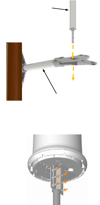
Mounting the Device
Mount the Bracket
The DK-0029A vertical pole mounting bracket has an
extension arm and a mounting pole as shown on the
right.
Mount the equipment extension arm to the utility pole
using bolts or bands.
Attach a steel mounting pole through the end of the
extension arm using the 5/8‖ attached bolt on the bottom
of the pole mount. Firmly tighten.
Attach The Extender Bridge to the Bracket
Use the provided mounting bracket and appropriate length
¼―diameter screws that are provided in the accessory kit to
attach the SecureMesh Extender Bridge to the mounting pole
(see the figure on the right).
Note that screws 1" in length can accommodate a pole
diameter up to 1½" while screws 2" in length accommodate a
pole diameter of 2-1/8‖.
The screws should be tightened to 20 foot-pounds (27
Newton-meters) of torque.
equipment
extension arm
utility pole
mounting pole
SecureMeshTM Extender Bridge Installation Guide
Trilliant Incorporated page 13 of 26
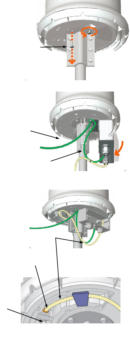
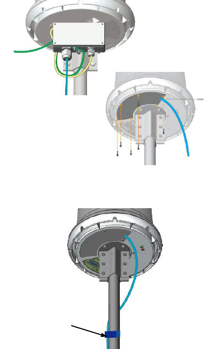
Grounding and Protecting the Device
The surge protector box should be attached to the
bottom of the Extender Bridge. The surge protector will
be attached using the ground screw as a pivot point
then the box will be swung into place against a mounting
bracket screw.
Remove the ground screw from the base of the
device, and then loosen (but do not remove) the
screw on the same side of the bracket as the
ground screw
Run the ground screw through the lug of the green
ground wire coming from the surge protector and
the hole in the surge protector bracket.
Before tightening the ground screw, remove a
section of the insulation on the ground wire which
will attach to the ground point on the mounting
structure and wrap this section around the ground
screw.
Pivot the box into place such that the other end of
the surge protector’s mounting bracket touches the
loosened screw. Tighten both screws.
Be sure to connect the ground wire to the
grounding point on the mounting structure.
Run the CAT5e cable under the gasket and plug it
into the Ethernet port in the cavity on the device
base (see the diagram to the right)
.
CAT5e
Ethernet Cable
8P8C Ethernet
Port
8P8C serial
port
View of underside with cover plate removed
ground wire
ground wire to
mounting
structure
ground screw
SecureMeshTM Extender Bridge Installation Guide
Trilliant Incorporated page 14 of 26
Attaching the NAN Antenna
Attach the 2.4 GHz NAN antenna to the N-type female
connector as shown in to the right. There are two N-
type connectors at the base of the Extender Bridge:
one N-type connector is open (exposed), and the other
is capped. Use the open connector.
Hand tighten or, equivalently, tighten the antenna using
a torque-limiting tool tighten it to 14 inch-pounds (1.5
Newton-meters), where 14 inch-pounds is
approximately the torque a person can achieve using
one hand.
Use self-fusing rubber insulation and sealing tape to
wrap the antenna bulkhead connector and the antenna
to avoid water penetration of any kind.
SecureMeshTM Extender Bridge Installation Guide
Trilliant Incorporated page 15 of 26
Connecting the Device to a Source of Power
The Power Service Unit can be used to provide PoE power and battery backup for the Extender Bridge.
Please refer to the Power Service Unit Installation Guide for more information (Trilliant document PL-0042A,
Installation Guide, SecureMesh 24V PSU). Alternatively, the site may have its own Uninterruptible Power
System that can be used along with a PoE injector to provide 24V power and data over an Ethernet cable;
terminating in an 8P8C connector as per TIA/EIA-568-B.
Connect the Power over Ethernet (PoE) injector to the Surge Protector
Both power and data are provided over the Ethernet cable connection to the Extender Bridge.
Always use CAT5e (outdoor CAT5) cable that is shielded (Shielded Twisted Pair – STP), UV protected, with a
drain-wire. The Extender Bridge has an auto-sensing Ethernet port and therefore, either a straight through or a
cross-connect cable may be used.
The cable seal gasket (glands) is water-tight and will not allow terminated cables to be passed through. The
cable will have to be re-terminated. Therefore, it may be best to perform the termination on the ground before
beginning the installation.
A sufficient portion of the cable shielding must be available to be connected to the ground bolt.
Run an un-terminated CAT5e cable through the open glands on the surge protector.
Strip the protective coating from the outside of the CAT5e cable to a sufficient length that the shield of the
cable may be connected to the ground lug of the surge protector and the twisted pairs may be connected
to the RJ45 or the connector block. Connect the cable shield (drain wire) to the internal ground lug.
Either terminate the cable from the PoE using an RJ45 connector or terminate all eight cables to the
terminator block. The screw down terminator block is removable from the base board of the surge
protector to ease connections. Please note that the pin-outs of the RJ45 are standard TIA/EIA-568-B. The
screw down terminal block wiring diagram is listed on the main board.
drain wire
crimp lug
grounding connection
inside surge protector
ground bolt
unprotected
CAT5e
Ethernet cable
from PoE power
source
watertight glands
PoE cable ↓
protected CAT5e
Ethernet cable provides PoE
power to Extender Bridge
SecureMeshTM Extender Bridge Installation Guide
Trilliant Incorporated page 16 of 26
Completing the installation
Check the connections and close the device
Check to ensure all connections and grounding are
proper, and replace the surge protector’s cover and the
Ethernet connection cover on the base of the Extender
Bridge. These screws should be tightened to 15 foot-
pounds (20 Newton-meters) of torque.
Secure the Cabling
Use sturdy cable ties or Velcro wraps (not included) to
secure all the cabling against strain, especially if the
installation is subject to high winds.
sturdy cable ties or
Velcro wraps
SecureMeshTM Extender Bridge Installation Guide
Trilliant Incorporated page 17 of 26
Streetlight Pole Mounting and Grounding
To install an Extender Bridge on a streetlight, observe the following procedures:
Mounting the Device
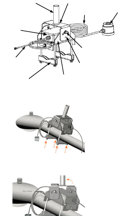
Mount the Bracket
Chose one of the two available Streetlight Installation
Kits from the Extender Bridge accessory list. The kits
vary only in the length of the cable to attach to the
streetlight photo cell.
If the clamp is not already separate from the main
bracket, remove the nuts from the bolts and separate
the clamp from the main bracket.
Place the main bracket over the light pole’s horizontal
extension arm. Place the clamp on the bolts and
secure with the nuts provided as shown on the right.
Hand tighten the nuts.
Make the mounting pipe plumb (straight) by moving the
main bracket from side to side and moving the plumb
adjustment bracket forward and backward. The
accuracy should be checked using a magnetic level.
When the mounting pipe is plumb, tighten all nuts.
photo cell tap
AC input
excess wire storage
clamp
Ethernet
PoE cable
power supply and
surge protection
plumb adjustment bracket
main bracket
mounting pipe
plumb adjustment screw
SecureMeshTM Extender Bridge Installation Guide
Trilliant Incorporated page 18 of 26
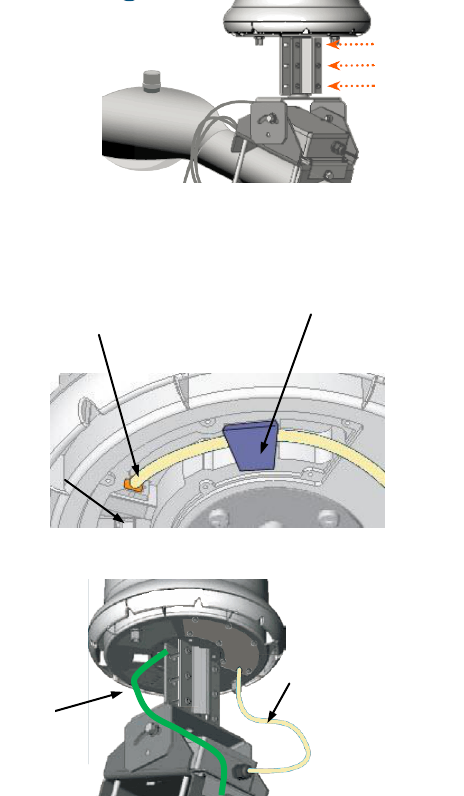
Attach The Extender Bridge to the Bracket
Use the provided mounting bracket and appropriate length
¼―diameter screws that are provided in the accessory kit to
attach the SecureMesh Extender Bridge to the mounting pole
(see the figure on the right).
Before tightening, rotate the device to ensure there is ample
room for the omnidirectional antennas to clear the mount
stand and streetlight pole.
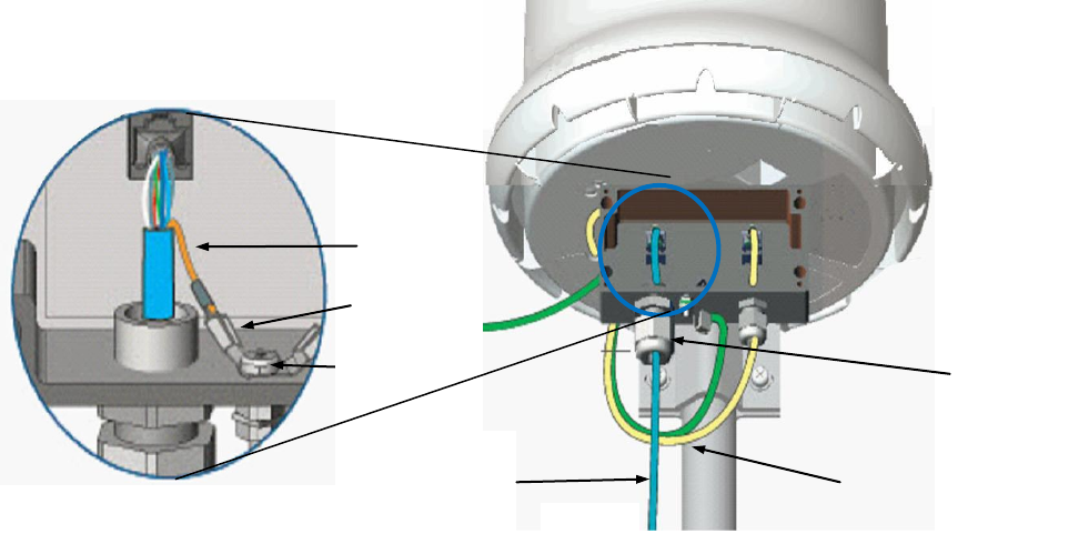
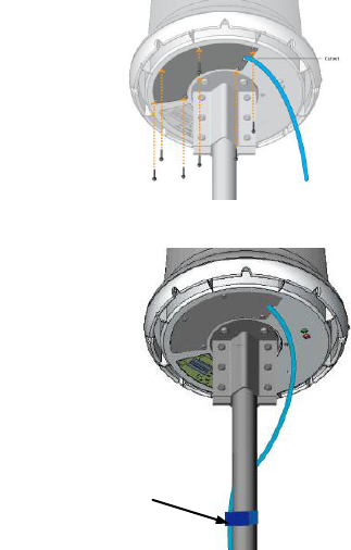
Attach the Ground Wire
Connect the Ethernet PoE cable to the Ethernet port at
the base of the Extender Bridge, pushing the 8P8C into
the socket on the bottom of the Extender Bridge until it
locks into place (as shown on the right). The Ethernet
PoE cable should be routed through the water protection
gasket.
Loosen the ground screw at the base of the Extender
Bridge. Remove a section of the insulation on the ground
wire that will attach to the ground point on the streetlight,
and wrap this section around the ground screw and
tighten the screw.
If the streetlight is completely metal, attach the other end
of the ground wire to the mounting hardware. If the
streetlight is a metal arm attached to a wooden pole the
ground wire must extend to a proper ground location.
Ethernet PoE cable
ground
wire
8P8C Ethernet
socket
8P8C
serial port
View of underside with cover plate removed
water intrusion
gasket

SecureMeshTM Extender Bridge Installation Guide
Trilliant Incorporated page 19 of 26
Attaching the NAN Antenna
Attach the Antenna
Attach the 2.4 GHz NAN antenna to the N-type female
connector as shown in to the right. There are two N-
type connectors at the base of the Extender Bridge:
one N-type connector is open (exposed), and the other
is capped. Use the open connector.
Hand tighten.
If you prefer to tighten the antenna using a
torque-limiting tool tighten it to 14 inch-
pounds (1.5 Newton-meters). 14 inch-
pounds is basically the torque a person can
achieve using one hand.
Use self-fusing rubber insulation and sealing tape to
wrap the antenna bulkhead connector and the antenna
to avoid water penetration of any kind.
SecureMeshTM Extender Bridge Installation Guide
Trilliant Incorporated page 20 of 26
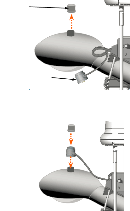
Connecting the Device to a Source of Power
The Streetlight Installation Kit is to be used with constantly powered streetlights that use standard photocell
adapters. The Streetlight Installation Kit is complete with an A/C to D/C power supply that also provides surge
protection.
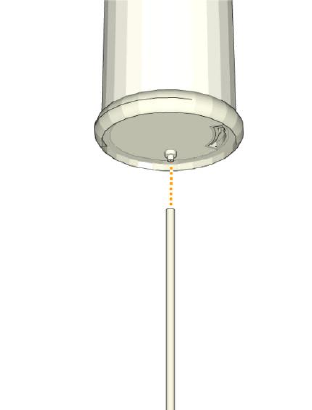
Connect to Streetlight AC Power
Locate the photocell on the light pole (usually located
on top of the street lamp) and remove it; twisting it
counter-clockwise and lifting it from the socket.
Connect the photocell adapter (power tap) to the
photocell socket; twisting clockwise until hand tight.
Replace the photocell on top of the photocell
adapter; twisting clockwise until hand tight.
Coil any excess cable. Place it in the space provided
under the mount stand and secure it.
photocell
photocell adapter /
power tap
SecureMeshTM Extender Bridge Installation Guide
Trilliant Incorporated page 21 of 26
Completing the Installation
Check the connections and close the device
Check to ensure all connections and grounding are
proper and replace the surge protection box cover and
the Ethernet cover to the base of the Extender Bridge.
These screws should be tightened to 15 foot-pounds
(20 Newton-meters) of torque.
Secure the Cabling
Use sturdy cable ties or Velcro wraps (not included) to
secure all the cabling against strain, especially if the
installation is subject to high winds.
sturdy cable ties or
Velcro wraps
SecureMeshTM Extender Bridge Installation Guide
Trilliant Incorporated page 22 of 26
COMMISSIONING THE EXTENDER BRIDGE
Configuring the SecureMesh Extender Bridge
Assuming the Extender Bridge is properly pre-provisioned, use of automatic provisioning as described in the
―Trilliant Network Element Management System (NEMS) Administration Guide‖ (Trilliant document number
TLT-CS-ADM-94) recommended.
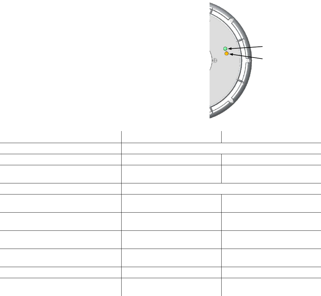
Monitoring the Power-On Sequence
When power is supplied to the SecureMesh Extender Bridge, it
starts a power-on sequence that can be monitored by observing
the pair of LED lights on the underside of the device.
The SecureMesh Extender Bridge must have access to a GPS
signal to complete its power-on sequence and start making
wireless network connections. The power-on sequence takes
up to 15 minutes, depending on how quickly the device can
acquire a GPS signal.
The tables that follow provide detailed descriptions of device
states indicated by the LED lights. When both LED lights are
illuminated and steady, the Extender Bridge has successfully
connected to the wireless network.
Device State
Link LED (Green)
Activity LED (Amber)
startup in progress
slow staggered blinking of both LEDs
startup failure
off
on
initializing processor (and acquiring GPS
signal)
blinks 4 times; repeats cycle
blinks 4 times; repeats cycle
initialization failure
fast, synchronized blinking of both LEDs
successful initialization, but failure to
locate hello
on
off
successful initialization; heard hello
off
blinking based upon RSSI signal
level
successful initialization; link is not
optimized, or is in pre-authorization
slow blink
blinking based upon RSSI signal
level
successful initialization; link is in standby
state on RSSI
fast blink
blinking based upon RSSI signal
level
WAN connected – NAN radio operational
on
on
WAN connected – NAN radio not
operational
on
blinks 4 times; repeats cycle
Link LED (Green)
Activity LED (Amber)
SecureMeshTM Extender Bridge Installation Guide
Trilliant Incorporated page 23 of 26
APPENDIX
Grounding Guidelines
Proper grounding protects both your SecureMesh device and any equipment connected to it. For the surge
protection circuitry built into the SecureMesh equipment to be effective, proper grounding of the unit is
necessary. Protection is essential if the unit is installed on tall structures or in areas subject to lightning.
Note that the techniques described in this appendix are intended as general guidelines and do not constitute a
comprehensive guide covering all installation scenarios. For maximum protection, contact a qualified
installation specialist who is familiar with your operating environments. If lightning is a threat in your area,
consider a consultation with a lightning and transient protection specialist.
General Grounding Strategy
To ensure optimal reliability, properly ground the metal base of the SecureMesh device. The most efficient
way to ground the device is to use a 10 AWG or larger wire to connect it to a ground point on the structure or
tower.
The three most common grounding points are:
The primary grounding point or the down lead
provided by an existing grounding system at the
installation site. For example, the grounding
system may be provided by a building's AC
electrical system, a streetlight’s power system,
or as part of a tower structure.
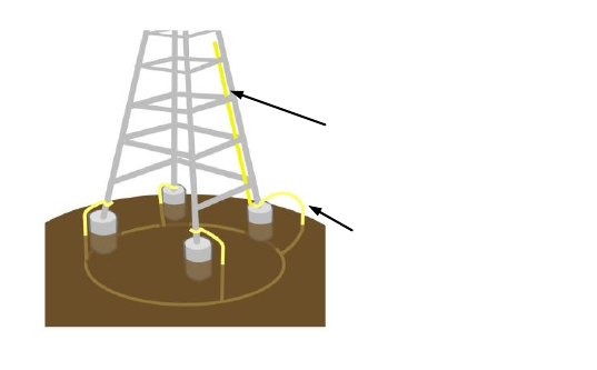
A 10-foot or longer copper-clad ground rod
driven into the earth. At a tower with multiple
legs, there will typically be one ground rod per
leg and a ground wire loop connecting each of
the rods as shown in the accompanying picture.
A cold-water pipe. Make sure it is well
connected to earth.
tower grounding at each leg
wired together underground
down lead tied to tower
grounding system
conventional tower grounding
SecureMeshTM Extender Bridge Installation Guide
Trilliant Incorporated page 24 of 26
Making Robust and Lasting Connections
Regardless of the grounding point you use, make sure the connections are capable of retaining low resistance
and integrity over time and with exposure to the elements by use of an antioxidant compound. For protection
against corrosion and rust, wrap all connections with a product such as Scotch® 130C or 2228 Rubber Mastic
Tape.
Grounding Checklist
When grounding a SecureMesh WAN device, use the following checklist to confirm that your installation is
adequately protected from power surges and lightning.
Install all lightning and surge protection devices in accordance with UL 96A installation requirements for
lightning protection systems and the NFPA 780 standard for lightning protection.
Connect a ground wire from the SecureMesh WAN device to a ground system on the utility pole, tower,
or building.
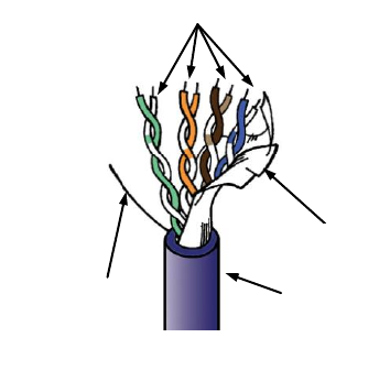
When using outdoor Ethernet cable, use UV protected,
Shielded Twisted Pair (STP) CAT5e cabling that includes a
drain wire. The drain wire and cable shield should be
connected to the appropriate ground location on the
SecureMesh WAN device; typically the ground lug inside the
surge protector or the ground point on the outside of the device.
Leave the other end of the drain wire at the power source
unconnected.
Use the proper size down lead to connect the SecureMesh
WAN device on a roof or tower to the ground system.
Whenever possible, verify that all points of the ground system
are tied together with less than 5 ohms resistance between any
two points.
For Towers and Rooftops
Use the proper size down lead to connect the SecureMesh WAN device on a roof or tower to the
ground system.
Run the CAT5e cable inside the tower structure, tying the cable to the tower leg at every 4 feet of
length. For increased protection, run the CAT5e cable through metallic conduit installed on the tower.
cable jacket
twisted pairs
drain wire
Shielded Twisted Pair (STP) Ethernet cable
with grounding drain wire
cable shield
SecureMeshTM Extender Bridge Installation Guide
Trilliant Incorporated page 25 of 26
APPENDIX B
Regulatory Information
Federal Communications Commission (FCC) compliance notices
This section includes the following FCC statements for the XBRG-1100-A and related SecureMesh™ Extender Bridges:
• FCC ID: RV7-5G1100 (Applies to XBRG-1100-A)
• Class A Interference Statement
• RF Radiation Exposure and Hazard Warning
• Non-Modification Statement
• Deployment Statement
Class A Interference Statement
This equipment has been tested and found to comply with the limits for a Class A digital device, pursuant to Part 15 of the FCC Rules.
These limits are designed to provide reasonable protection against harmful interference in a commercial installation. This equipment
generates, uses, and can radiate radio frequency energy and, if not installed and used in accordance with the instructions, may cause
harmful interference to radio communications. However, there is no guarantee that interference will not occur in a particular installation.
If this equipment does cause harmful interference to radio or television reception, which can be determined by turning the equipment off
and on, the user is encouraged to try to correct the interference by one or more of the following measures:
• Reorient or relocate the receiving antenna.
• Increase the separation between the equipment and receiver.
• Connect the equipment into an outlet on a circuit different from that to which the receiver is connected.
• Consult the dealer or an experienced radio/TV technician for help.
FCC Caution:
This device complies with Part 15 of the FCC Rules. Operation is subject to the following two conditions: (1) This device may not
cause harmful interference, and (2) this device must accept any interference received, including interference that may cause undesired
operation.
RF Radiation Exposure & Hazard Statement
To ensure compliance with FCC RF exposure requirements, this device must be installed in a location such that the antenna of the
device will be greater than 20 cm (8 in.) away from all persons. Using higher gain antennas and types of antennas not covered under
the FCC certification of this product is not allowed. Installers of the radio and end users of the product must adhere to the installation
instructions provided in this manual. This transmitter must not be co-located or operated in conjunction with any other antenna or
transmitter.
Non-Modification Statement
Use only the supplied internal antenna. Unauthorized antennas, modifications, or attachments could damage the XBRG-1100-A and
related SecureMesh™ products and violate FCC regulations. Any changes or modifications not expressly approved by the party
responsible for compliance could void the user's authority to operate this equipment.
Deployment Statement
This product is certified for indoor deployment only in the 5150 – 5250 MHz band. Do not install or use this product outdoors in that
frequency band in the United States.
Dynamic Frequency Selection (DFS) in the 5.0 GHz UNII bands
The XBRG-1100-A has been prohibited from operating in the 5600 to 5650 MHz frequency band for the US and Canada in order to
comply with the DFS requirements as outlined in the FCC Part 15, Subpart E rules.

SecureMeshTM Extender Bridge Installation Guide
Trilliant Incorporated page 26 of 26
Canadian IC Statements
IC: 6028A-5G1100 (Applies to XBRG-1100-A).
This device complies with ICES-003 and RSS-210 of Industry Canada.
Operation is subject to the following two conditions:
1. This device may not cause interference, and
2. This device must accept any interference, including interference that may cause undesired operation of the device.
Ce dispositif est conforme aux normes NMB003 et CNR-210 d’Industrie Canada.
1. L’utilisation de ce dispositif est autorisée seulement aux conditions suivantes :
2. il ne doit pas produire de brouillage et l’utilisateur du dispositif doit être prêt à accepter tout brouillage radioélectrique reçu, même si
ce brouillage est susceptible de compromettre le fonctionnement du dispositif.
RF Radiation Exposure & Hazard Statement
To ensure compliance with RSS-102 RF exposure requirements, this device must be installed in a location such that the antenna of the
device will be greater than 20 cm (8 in.) away from all persons. Using higher gain antennas and types of antennas not covered under
the IC certification of this product is not allowed. Installers of the radio and end users of the product must adhere to the installation
instructions provided in this manual. This transmitter must not be co-located or operated in conjunction with any other antenna or
transmitter.
Exposition aux radiations RF & Mention de danger
Pour assurer la conformité avec les exigences RSS-102 d'exposition aux RF (Radio Fréquences), cet appareil doit être installé dans un
endroit ou l'antenne de l'appareil sera située à une distance de plus de 20 cm (8 po) de toutes personnes. L’utilisation d'antennes à
gain plus élevé et les types d'antennes qui ne sont pas couverts en vertu de la certification IC de ce produit n'est pas autorisée. Les
installateurs de la radio et les utilisateurs du produit final doivent se conformer aux instructions d'installation fournies dans ce manuel.
Cet émetteur ne doit pas être co-implanté ou exploité en conjonction avec toute autre antenne ou transmetteur.
Deployment Statement
This product is certified for indoor deployment only in the 5150 – 5250 MHz band. Do not install or use this product outdoors in that
frequency band in Canada.
Déclaration de déploiement
Ce produit est certifié pour le déploiement à l'intérieur tout en rencontrant les limites de cette bande de fréquences: 5150 - 5250 MHz.
Ne pas installer ou utiliser ce produit à l'extérieur au Canada, si cette bande de fréquences ne peut ne peut être rencontrée.
Trilliant Incorporated
1100 Island Drive, Redwood City, CA 94065 USA
+1.650.204.5050
www.trilliantinc.com
Trilliant™, CellReader®, CellGateway™, SecureMesh™, SerViewCom®, UnitySuite™, SkyPilot®, SyncMesh™, the Trilliant logo, and the
SkyPilot logo are trademarks of Trilliant Incorporated and/or its subsidiaries. All other trademarks are the property of their respective owners.
This material is provided for informational purposes only; Trilliant assumes no liability related to its use and expressly disclaims any implied
warranties of merchantability or fitness for any particular purpose.
All specifications, descriptions, and information contained herein are subject to change without prior notice.
Copyright © 2010 Trilliant Incorporated. ALL RIGHTS RESERVED.