Trilliant Networks GW-SD1010 802.11 Based, Fixed Wireless Node User Manual gateway
Trilliant Networks, Inc. 802.11 Based, Fixed Wireless Node gateway
UserManual.wiki
>
Trilliant Networks
>
GW SD1010 User Manual
User Manual
Navigation menu
Upload a User Manual
Namespaces
Wiki Guide
HTML
PDF
Info
Views
User Manual
Discussion / Help
Navigation
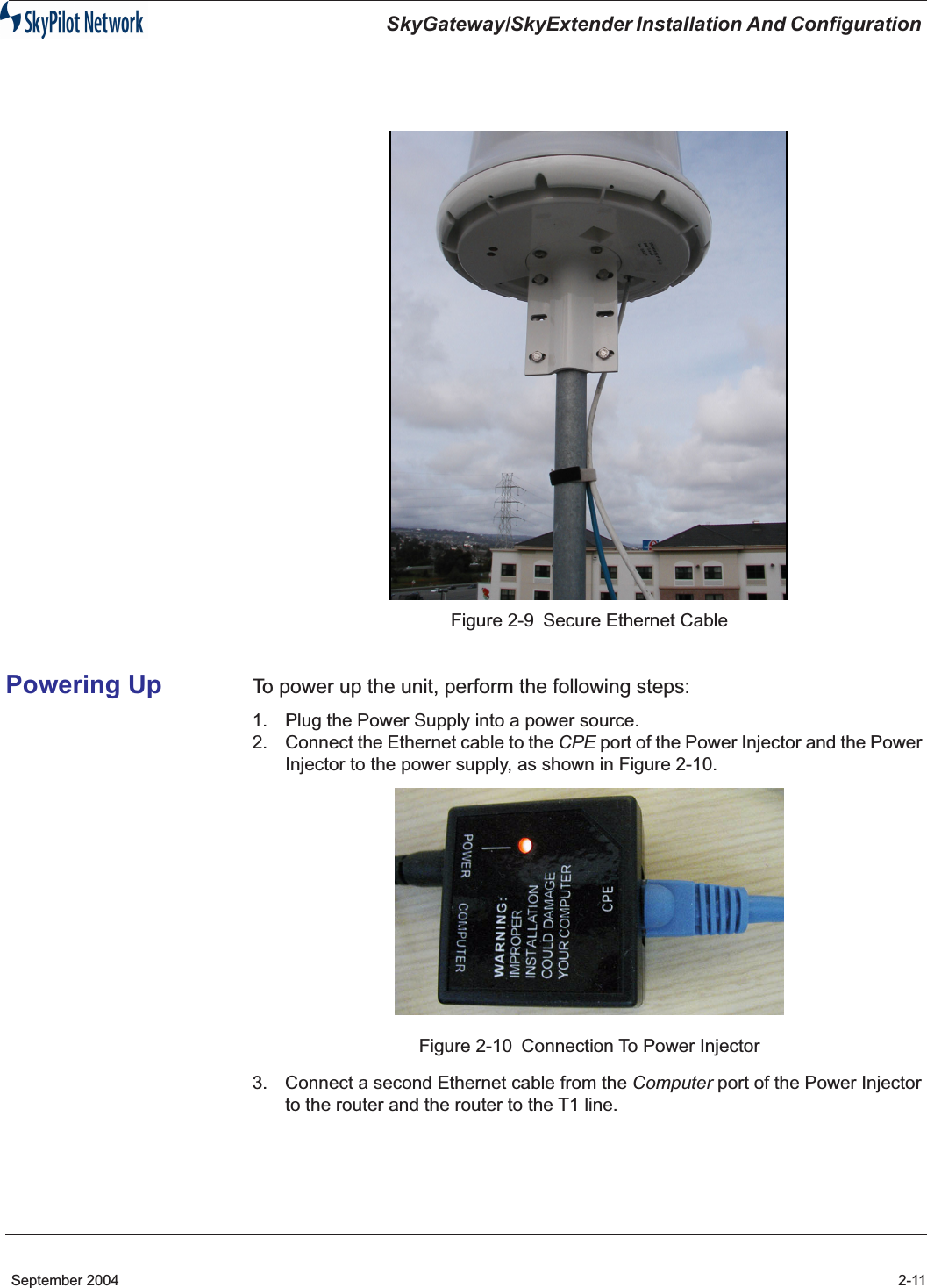
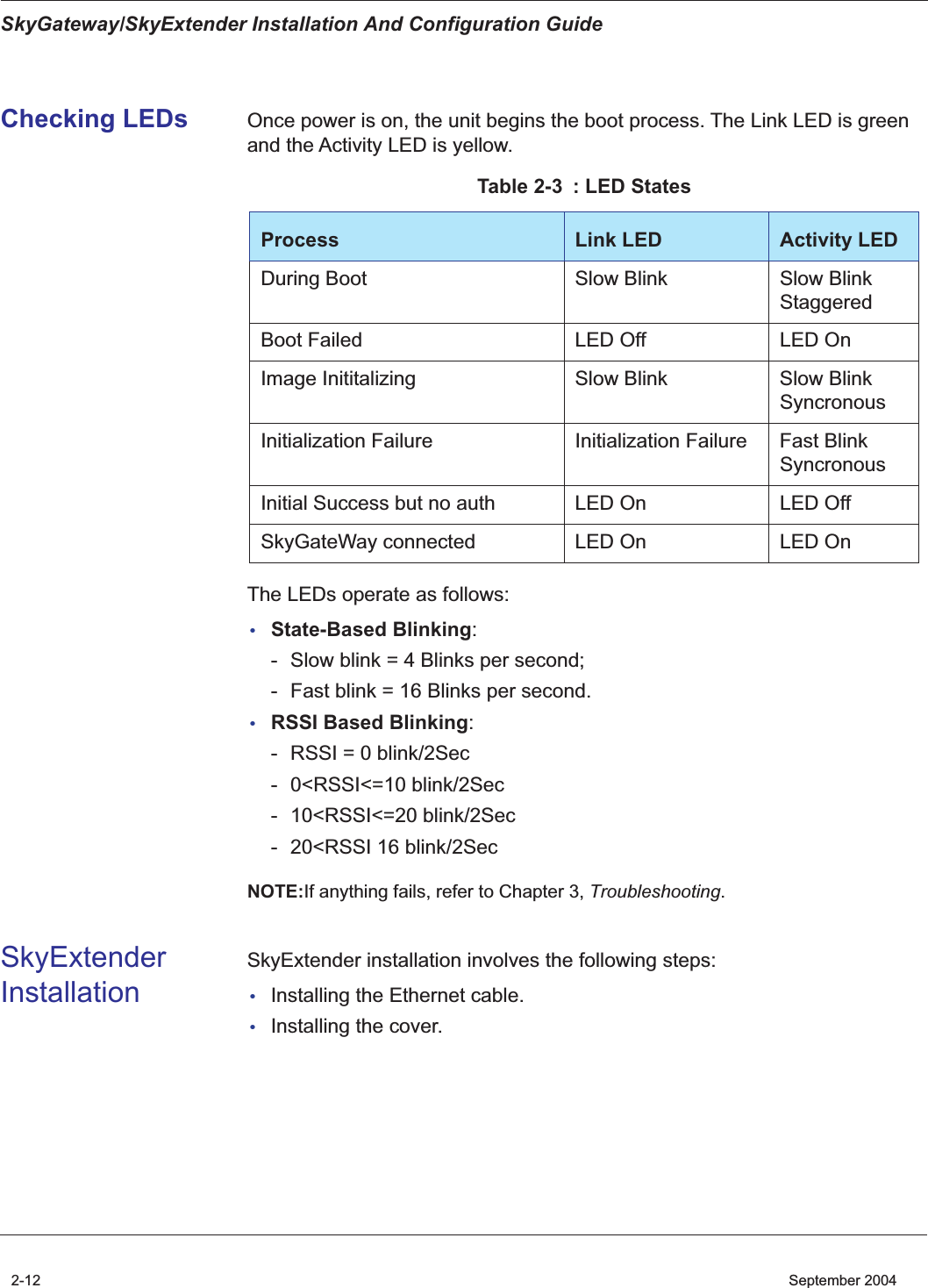
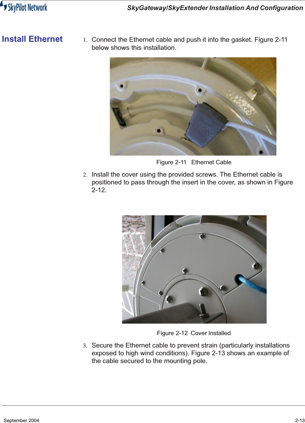
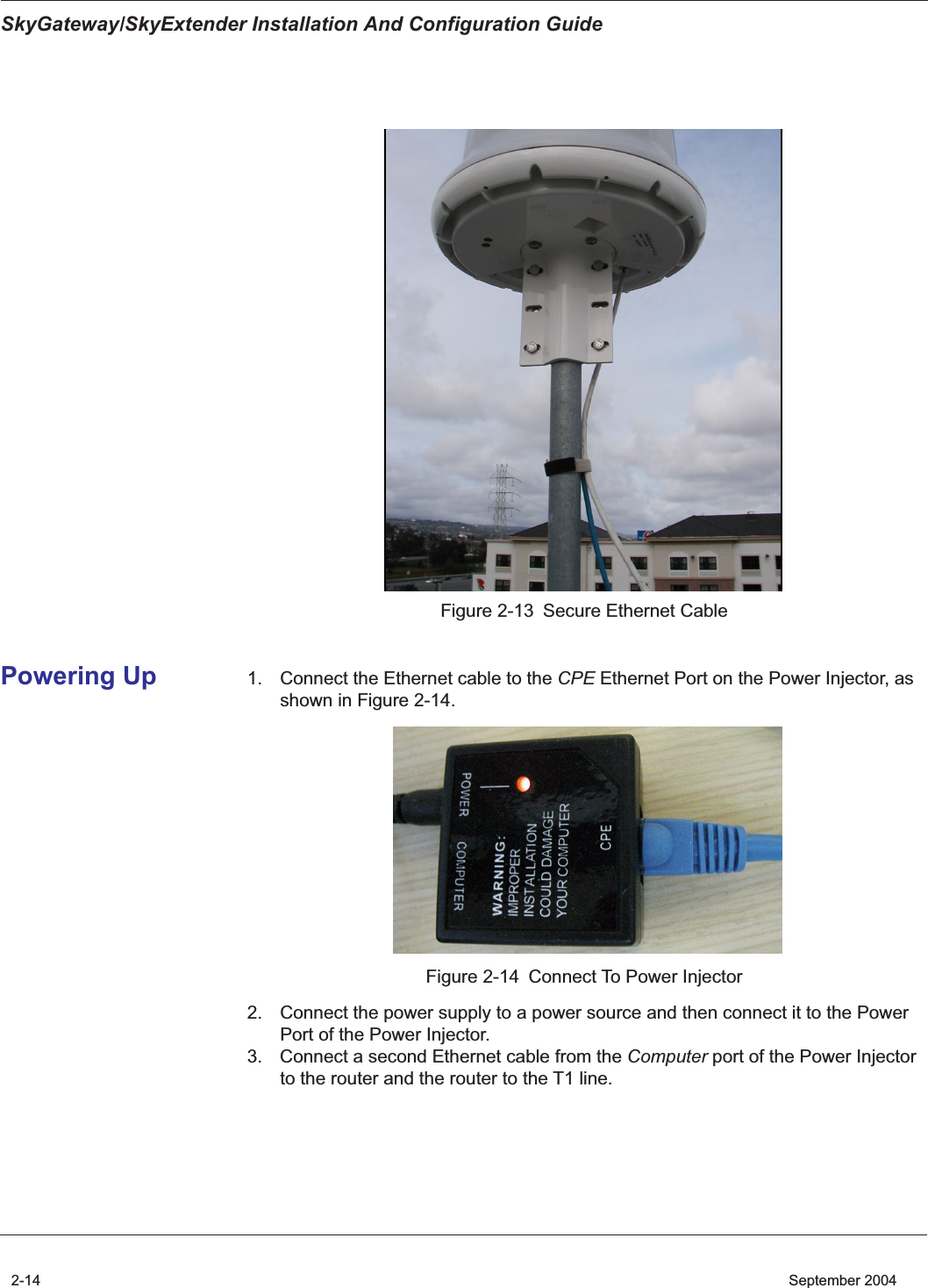
![Copyright Information© 2004 SkyPilot Network, Inc. All rights reserved. Broadband Without Limits, SkyConnector, SkyControl, SkyExtender, SkyGateWay, SkyPilot, SkyPilot Network, SkyProvision, the SkyPilot logo, and other designated trademarks, trade names, logos, and brands are the property of SkyPilot Network, Inc. or their respective owners.FCC Radio Frequency Interference StatementSkyGateWay/SkyExtender FCC Number: RV7-GW-SD1010This equipment has been tested and found to comply with the limits for the class B digital device, pursuant to part 15 of the FCC Rules. These limits are designed to provide reasonable protection against interference in a residential installation. This equipment generates, uses and can radiate radio frequency energy and if not installed, and used in accordance with the instructions, may cause harmful interference to radio communications. However, there is no guarantee that interference will not occur in a particular installation. If this equipment does cause harmful interference to radio or television reception, which can be determined by turning the equipment off and on, the user is encouraged to try and correct the interference by one or more of the following measures: This equipment has been certified to comply with the limits for a class B computing device, pursuant to FCC Rules. In order to maintain compliance with FCC regulations, shielded cables must be used with this equipment. Operation with non-approved equipment or unshielded cables is likely to result in interference to radio and TV reception. The user is cautioned that changes and modifications made to the equipment without the approval of manufacturer could void the user's authority to operate this equipment. Maximum Permissible Exposure In order to meet the FCC’s requirement of 1 mW/cm2 for Maximum Permissible Exposure (MPE) at 5.8 GHz, the SkyGateway/SkyExtender units must be located a minimum of 1 meter (39.4 inches) from all persons. This distance is determined based upon the aforementioned 1 mW/cm2 limit, measured data, and the far-field peak power density equation below: ()()[]SdGP 20/10282.0 += where: d = MPE distance in cm P = Power in dBm (peak) G = Antenna Gain in dBi S = Power Density Limit in mW/cm2 (1 mW/cm2) Certified laboratory measurements indicate that the FCC’s Power Density Limit of 1 mW/cm2 is met at a distance of 39 cm (15.4 inches). However a distance of 1 meter is recommended in order to introduce a margin of safety equivalent to 6.6 times the FCC’s Power Density Limit. This margin of safety compensates for the assumption of a point source antenna in the far-field equation. 1301 Shoreway Road, Suite 211Belmont, CA 94002-4106Phone 650-413-8000email: support@skypilot.comWeb: www.skypilot.com](https://usermanual.wiki/Trilliant-Networks/GW-SD1010/User-Guide-492725-Page-2.png)