Trilliant Networks GW-SD1010 802.11 Based, Fixed Wireless Node User Manual gateway
Trilliant Networks, Inc. 802.11 Based, Fixed Wireless Node gateway
User Manual

Installation And Configuration Manual
Revision:
1.0
S/W Version:
1.0
Date:
Septembert 2004
SkyGateway And
SkyExtender

Copyright Information
© 2004 SkyPilot Network, Inc. All rights reserved. Broadband Without Limits, SkyConnector, SkyControl,
SkyExtender, SkyGateWay, SkyPilot, SkyPilot Network, SkyProvision, the SkyPilot logo, and other designated
trademarks, trade names, logos, and brands are the property of SkyPilot Network, Inc. or their respective owners.
FCC Radio Frequency Interference Statement
SkyGateWay/SkyExtender FCC Number: RV7-GW-SD1010
T
his equipment has been tested and found to comply with the limits for the class B digital device, pursua
nt
t
o part 15 of the FCC Rules. These limits are designed to provide reasonable protection against i
n
terferen
ce
i
n a residential installation. This equipment generates, uses and can radiate radio frequency energy and
if
n
ot installed, and used in accordance with the instructions, may cause harmful interference to rad
io
c
ommunications. However, there is n
o
guarantee that interference will not occur in a particular installatio
n.
I
f this equipment does cause harmful interference to radio or television reception, which can be determin
ed
b
y turning the equipment off and on, the user is encouraged to try and
co
r
rect the interference by one
or
m
ore of the following measures:
T
his equipment has been certified to comply with the limits for a class B computing device, pursuant
to
F
CC Rules. In order to maintain compliance with FCC regulations, shielded cables mus
t
be used with th
is
e
quipment. Operation with non-
a
pproved equipment or unshielded cables is likely to result in interferen
ce
t
o radio and TV reception. The user is cautioned that changes and modifications made to the equipme
nt
w
ithout the approval of manufacturer could void the user's authority to operate this equipment.
Maximum Permissible Exposure
I
n order to meet the FCC’s requirement of 1 mW/cm2
for Maximum Permissible Exposure (MPE) at 5
.8
G
Hz, the SkyGateway/SkyExtender units must be located a min
i
mum of 1 meter (39.4 inches) from a
ll
p
ersons. This distance is determined based upon the aforementioned 1 mW/cm2
limit, measured data, a
nd
t
he far-field peak power density equation below:
()()
[]
S
dGP 20/
10282.0 +
=
w
here: d = MPE distance in cm
P = Power in dBm (peak)
G = Antenna Gain in dBi
S = Power Density Limit in mW/cm2 (1 mW/cm2)
C
ertified laboratory measurements indicate that the FCC’s Power Density Limit of 1 mW/cm2
is met at
a
d
istance of 39 cm (15.4 inches). However a distance o
f
1 meter is recommended in order to introduce
a
m
argin of safety equivalent to 6.6 times the FCC’s Power Density Limit. This margin of safe
ty
c
ompensates for the assumption of a point source antenna in the far-field equation.
1301 Shoreway Road, Suite 211
Belmont, CA 94002-4106
Phone 650-413-8000
email: support@skypilot.com
Web: www.skypilot.com

SkyGateway/SkyExtender Installation And Configuration
September 2004 iii
Table Of Contents
Introduction ................................................................................................. 1-1
System Overview ........................................................................................................... 1-2
Physical Specifications and Installation..................................................................... 1-2
Power ........................................................................................................................ 1-2
Antennas ................................................................................................................... 1-2
Modules ..................................................................................................................... 1-2
Connectors ................................................................................................................ 1-3
Network Architecture...................................................................................................... 1-4
Physical and Link Layers........................................................................................... 1-4
Routing ...................................................................................................................... 1-4
Scheduling and Bandwidth Management .................................................................. 1-5
Installation ................................................................................................... 2-1
Plan The Installation ...................................................................................................... 2-2
Site Survey ................................................................................................................ 2-2
Frequency.................................................................................................................. 2-2
Unpack The Equipment ................................................................................................. 2-3
Equipment Inventory.................................................................................................. 2-3
Wind Loading Requirements ..................................................................................... 2-5
Grounding.................................................................................................................. 2-5
Lightening .................................................................................................................. 2-5
Mount The Unit .............................................................................................................. 2-6
Install Cabling ................................................................................................................ 2-7
SkyGateWay Installation ........................................................................................... 2-8
Install Ethernet ...................................................................................................... 2-8
Installing Optional Serial Adapter Cover ............................................................... 2-9
Powering Up........................................................................................................ 2-11
Checking LEDs.................................................................................................... 2-12
SkyExtender Installation .......................................................................................... 2-12
Install Ethernet .................................................................................................... 2-13
Powering Up........................................................................................................ 2-14
Checking LEDs.................................................................................................... 2-15
RJ-45 Pins ............................................................................................................... 2-16
Serial Port Signaling and Cabling Using a DB-9 Adapter........................................ 2-16
Troubleshooting ......................................................................................... 3-1
Connecting Via a Serial Link.......................................................................................... 3-2
Troubleshooting Procedures.......................................................................................... 3-5
Specifications ............................................................................................. 4-1
Product Specifications ................................................................................................... 4-2

SkyGateway/SkyExtender Installation And Configuration Guide
iv September 2004

SkyGateway/SkyExtender Installation And Configuration
September 2004 1-1
C
HAPTER
1
I
NTRODUCTION
A SkyPilot System is made up of the following components:
SkyGateWay
. This network element provides an interface between the
network and the Internet or WAN via a 10/100BASE-T connector. A
minimum of one SkyGateway unit is required for a SkyPilot System;
additional units provide redundancy in case of a power failure or other
problem at the main gateway.
SkyExtender
. These nodes connect directly to a SkyGateway device, to
other SkyExtender nodes, and to SkyConnector Indoor and SkyConnector
Outdoor subscriber units. They provide the framework of the network. A
SkyExtender is typically installed on a roof, tower, light or utility pole, or
other fixed location. In a rooftop installation, a 10/100BASE-T Ethernet
connection is available for subscriber usage.
SkyConnector Indoor and SkyConnector Outdoor
. These units are
installed in subscribers’ homes or offices. A SkyConnector provides an
interface between the subscriber’s computer and the network. The
interface between the SkyConnector and the network is via a wireless
connection to a SkyExtender. The interface to the subscriber’s computer is
via an Ethernet cable. The outdoor unit typically provides greater range
than the indoor unit and is normally installed on an eave or roof. The
indoor unit is installed on a windowsill or in a window frame by the
subscriber without a truck roll and offers simple plug-and-play
configuration.
This manual provides instructions for installing and maintaining
SkyGateWays and Sky Extenders. See the
SkyConnector Indoor Unit
and
SkyConnector Outdoor Unit Installation Guides
for information about those
products.

SkyGateway/SkyExtender Installation And Configuration Guide
1-2 September 2004
System Overview
SkyGateWay basestations and SkyExtender nodes form the backbone of a SkyPilot
System.
Both devices feature:
•A compact, lightweight design that permits easy installation in a wide range of loca-
tions.
•High-power, 360° coverage.
•An efficient single connection for both power and data.
SkyGateWay and SkyExtender units are virtually identical, differing only in their soft-
ware. SkyGateWay basestations use a superset of the SkyExtender software that
includes the necessary programming to communicate with an external network.
The SkyExtender is comprised of five separate modules: baseband
motherboard, mPCI radio module, switchboard, and antenna array.
Physical
Specifications and
Installation
Each SkyGateWay or SkyExtender is only 18 inches high, 12 inches in
diameter, and 14 pounds in weight. The compact size and light weight mean
that these units can be installed on existing structures such as utility poles,
commercial buildings, homes, billboards, and water towers. Each unit
comes with a mounting bracket that fits over a standard 1.25-inch-diameter
pole. Operating temperatures can range from -40°C to 55°C (-40°F to
130°F).
Power
Because they use Power over Ethernet (PoE) and draw only about 10 watts,
the only cabling these units require is CAT-5 Ethernet cable. There is no
need to lease dedicated poles or run power cables, and no special tools are
required for installation.
Antennas
The eight antennas in a basestation or node provide sectorized 360°
coverage. Each antenna has a horizontal beamwidth of 45°, a vertical
beamwidth of 6.5°, and a gain of 18 dBi.
Modules
The motherboard has a PowerPC CPU, volatile and non-volatile memory, a
DC power interface, and interfaces to other system components.
An mPCI radio enables a SkyGateWay or SkyExtender to transmit and
receive in the 5.8GHz band using modulation rates of 6 to 54Mbps,
providing a peak EIRP of 44.5 dBm (28.2W). The radio currently supports a
range of center frequencies from 5745MHz-5805MHz. Each channel is
20MHz wide and can configured on 5MHz frequency granuality. Up to 4 non-

SkyGateway/SkyExtender Installation And Configuration
September 2004 1-3
overlapping channels can be supported. In an environment free from
significant interference in the UNII band, as many as four SkyGateWay or
SkyExtender units can be installed at a single location, each configured to
use a different channel.
The radio module also contains the wireless MAC and Physical Layer logic,
implementing the 802.11a hardware specification via an Atheros chipset.
The radio module connects to the motherboard for data and to the
switchboard for RF.
A switchboard provides the connection between the radio and the antenna
array. It provides antenna selection and amplifies the radio signal.
An integrated GPS receiver in both SkyGateWay and SkyExtender
basestations is used by SkyControl software to synchronize transmissions
within the network. It connects directly to the motherboard. The GPS
antenna is positioned on top of the antenna array assembly inside the
SkyGateWay enclosure.
Connectors
A RJ-45 jack enables a SkyGateWay to receive power and connect to an
external network. The same jack on the SkyExtender is normally only used
for power, but can also be used to connect directly to a subscriber’s network
or computer. (Both units come with a Power over Ethernet injector module
that combines incoming data and power onto one Ethernet jack that
connects to the SkyGateWay or SkyExtender device.)
An optional serial adapter (RJ-45 connector) permits local access to a
command-line interface (CLI) to change the unit’s settings.

SkyGateway/SkyExtender Installation And Configuration Guide
1-4 September 2004
Network Architecture
The SkyPilot system software manages communications protocols at all
levels, from RF to routing. It carefully manages SkyGateWay, SkyExtender,
and subscriber nodes to create the best possible network performance.
SkyProvision software is used to configure the system.
The SkyPilot System operates as a Layer 2 network. All subscriber traffic
goes to and from the network via an external switch or router attached to the
Ethernet bridge in a SkyGateWay basestation. Peer-to-peer communication
is not permitted within a SkyPilot System.
Physical and Link
Layers
Physical Layer
. At the RF layer, the components of a SkyPilot System use
standard 802.11a modulation operating in the 5.8GHz range. The Physical
Layer SkyPilot protocol conforms to the 802.11a specifications with the
addition of a synchronous one-second frame. The timing of this frame is
derived from a GPS receiver in each SkyGateWay and SkyExtender. The
frame’s signal is used to control transmission and reception in the network,
and also provides a reference for the “hello message” exchange (a beacon/
response sequence that allows nodes and gateways to establish
connections).
Data Link (MAC) Layer
. At the MAC layer, SkyPilot implements a
synchronization protocol that takes advantage of the one-second RF frame
to establish links and exchange secure, rate-controlled data between
devices.
Routing
Above the MAC layer, SkyControl brings into play a dynamic routing protocol
that ensures the most efficient utilization of network resources and provides
for rapid rerouting around link and device failures. SkyControl allows
SkyExtender nodes and SkyConnector subscriber units to join the network
automatically.
When a SkyExtender node connects to the network, it selects an optimum
route to a SkyGateWay. The route selection considers link capacity
(modulation rate), and the number of hops between the node and the
gateway. Once a route is selected, all user traffic is forwarded via this path
unless conditions change. Rerouting is necessary (and automatic) when a
link or node is lost. The SkyPilot system also automatically reroutes traffic
when it determines that a lower cost route is consistently available. (A
connection’s “cost” is determined by the number of hops it requires and the
modulation rates on each of the connection’s component links.)

SkyGateway/SkyExtender Installation And Configuration
September 2004 1-5
Scheduling and
Bandwidth
Management
As mentioned, the SkyPilot System supplements the 802.11 protocol with
sophisticated synchronization. By transmitting over different antennas in
different 100us mini-slots of the one-second synchronization frame, a
SkyPilot basestation or node provides 360° coverage through multiple high-
power point-to-point connections. In addition, highly accurate traffic rate
control and jitter control are enabled.
Bandwidth management within a network presents a particular challenge
due to the high number of interconnections, with each SkyExtender node
typically communicating with a multitude of others. The SkyPilot system
ensures that mini-slots are provided over each link, with the number of mini-
slots used by each pair of nodes varying as subscriber bandwidth demand
changes.
The SkyPilot system provides rate control for subscriber traffic both in the
downstream (SkyGateWay to SkyConnector) and upstream (SkyConnector
to SkyGateWay) directions. Maximum upstream and downstream rates can
be specified for each subscriber. In conditions of oversubscription, when the
overall bandwidth demand is higher than system capacity, the individual
subscriber data rates will be reduced proportionately.

SkyGateway/SkyExtender Installation And Configuration Guide
1-6 September 2004


SkyGateway/SkyExtender Installation And Configuration Guide
2-2 September 2004
Plan The Installation
Site Survey
In a typical wide-area wireless network utilizing SkyPilot units, the SkyGateWay is
installed on the roof of a tall building or tower. The direct coverage area of the
SkyGateWay is generally proportionate to the height of the installation.
A SkyGateWay may also be used in smaller scale networks. Examples include high-
capacity business or academic campus interconnection, or a localized access
network. In this case, the SkyGateWay could be installed on a local, medium height
building or utility pole.
The SkyExtender may be installed on home rooftops, tall buildings, or on light or
utility poles.
Refer to the
Site Planning
document for more information.
Frequency
SkyPilot recommends that an operator utilize a spectrum analyzer to scan the UNII
spectrum prior to installing one or more SkyGateWays. This information will be
necessary later when configuring the frequency. See the
SkyPilot Network
Management Guide
for more information about frequency
.
SkyGateway/SkyExtender Installation And Configuration
September 2004 2-3
Unpack The Equipment
The SkyGateWay and SkyExtender are each shipped separately. Each box
contains the installation kits described in the tables below. Prior to opening
the box(es), inspect the unit(s) for damage. If damage is present, contact the
shipping company immediately. Additionally, contact SkyPilot if an advanced
replacement is required. After the equipment is unpacked, it is
recommended that you keep the shipping box(es). This ensures proper
packaging of the equipment in the event that a unit must be returned to the
factory for any reason.
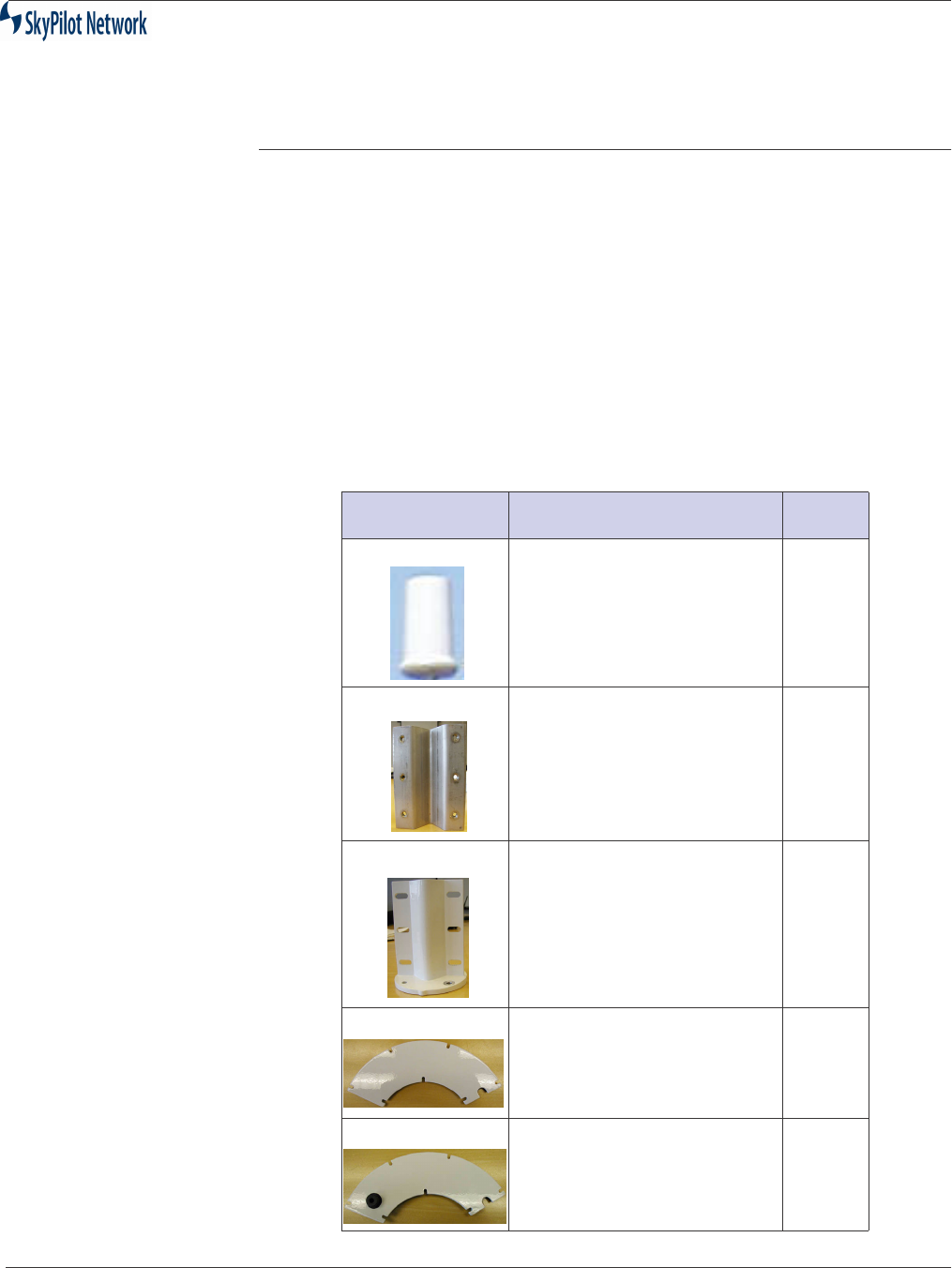
Equipment
Inventory:
SkyPilot is supplied with the following components:
Table 2-1 : Installation Kit
Part Description Qty
SkyGateWay Unit 1
Clamp Mount 1
Clamp 1
Cover 1
Cover With Serial Adapter
(SkyGateway Only; can be
purchased for SkyExtender)
1
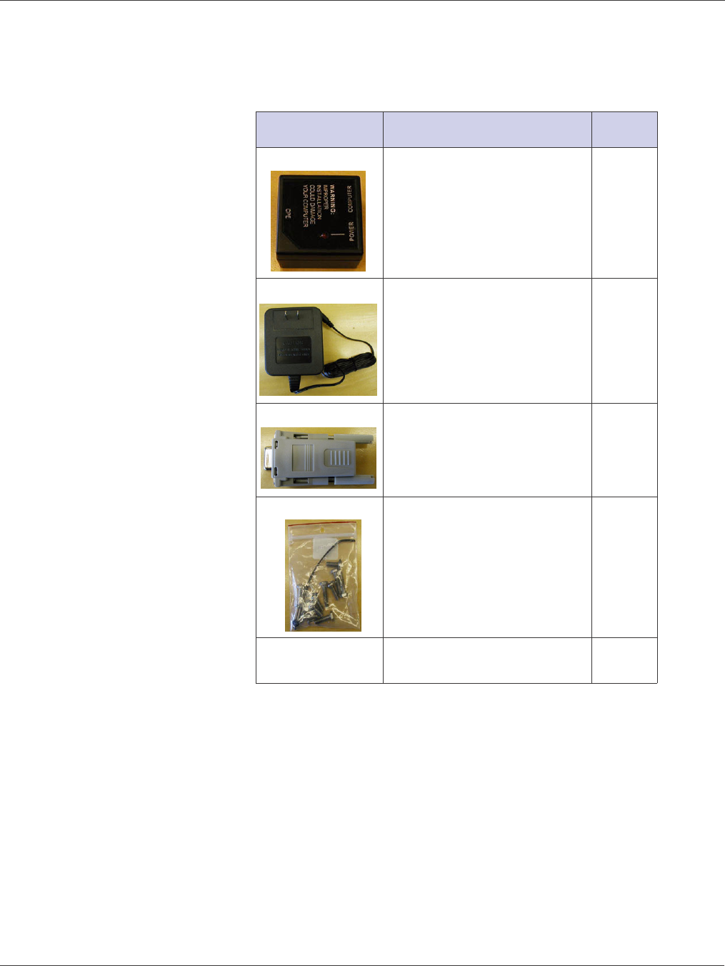
SkyGateway/SkyExtender Installation And Configuration Guide
2-4 September 2004
Power Injector 1
Power Supply 1
DB-9 Serial Adapter 1
Hardware Kit
CD with software and
product manuals
1
Table 2-1 : Installation Kit (Continued)
Part Description Qty
SkyGateway/SkyExtender Installation And Configuration
September 2004 2-5
.
Wind Loading
Requirements
The unit is designed to withstand wind speeds of up to 100mph while
mounted on up to a four-foot long 1.25 inch steel pole.
Grounding
In accordance with NEC (National Electric Code), the grounding conductor
must be a minimum wire gage of 10 AWG, Cu, solid.
Lightening
A primary lightening protector is not provided but is recommended.
Lightening protectors must be installed and grounded as set forth in the
NEC. If a primary protection is not used, the cabling is limited to 140 feet and
must be installed in accordance with NEC section 725-54 (c) and 800-30.
Table 2-2 : Tools Required For Installation
Tool Purpose
Magnetic Level Pole Mounting
1.25-inch Diameter Steel Pole Pole Mounting
7/16-inch combo wrench with open and close
ends
Unit Mounting
Phillips Screwdriver Unit Mounting
Spool of Category 5 cable Unit Configuration
RJ-45 Connectors: SkyPilot recommends using
CAT5 cables with RJ-45 connectors that do not
have a protective “boot” on the RJ-45 clip.
These booted connectors will fit in the RJ-45
ports (serial and ethernet/power), but the extra
plastic makes them difficult to remove.
Unit Configuration
RJ-45 Crimp Tool Unit Configuration
Laptop PC w/Terminal Emulator Software,
Network Interface Card, and Web Browser
Unit Configuration
WARNING
Failure to follow equipment installation instructions could damage the
assembly and render the unit inoperable. Read the entire procedure
before installing. Contact SkyPilot or your reseller with any technical
questions.
!
SkyGateway/SkyExtender Installation And Configuration Guide
2-6 September 2004
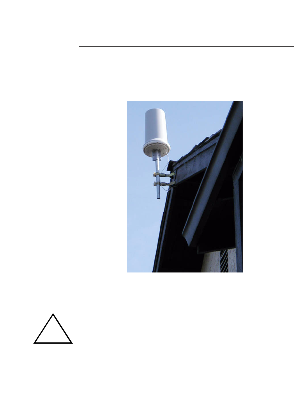
Mount The Unit
A mounting bracket is provided with the units. This bracket fastens to a standard
1.25-inch diameter steel pole. Any mounting system that meets local wind-loading
regulations and provides a 1.25-inch diameter by 5-inch long connecting surface will
be satisfactory. Attach the magnetic level to the pole to make sure the pole and unit
are aligned properly. The photograph below shows a possible unit installation.
Figure 2-1 Possible Unit Installation
.
WARNING
All bolts on the antenna assembly and mounting bracket must be
tightened to the proper torque specifications. The unsupported pole
length should be no greater than four feet.
!
SkyGateway/SkyExtender Installation And Configuration
September 2004 2-7
Install Cabling
NOTE:
Cables must be installed in accordance with NEC Article 725 and 800, and
all requirements must meet in relationship to clearances with power lines
and lighting conductors. All cabling must be category 5e per TIA/EIA-568-
B.2.
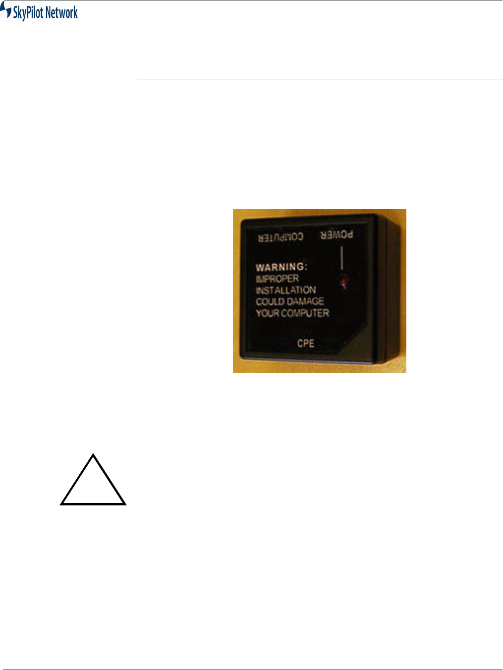
Both units support Power over Ethernet (PoE) utilizing the Power Injector provided,
as shown in Figure 2-2.
Figure 2-2 Power Injector
.
Both units provide a 10/100bT connector and the SkyGateWay provides a serial
interface. The 10/100bT Ethernet port provides interconnectivity for user and
network traffic, while the serial port is used for local access to the Command Line
Interface.
To install SkyGateWay, see “SkyGateWay Installation” on page 2-8.
To install SkyExtender. see “SkyExtender Installation” on page 2-12.
WARNING
The units should be installed with the
SkyPilot-provided Power Injector only
.
The use of other PoE Power Injectors could result in damage to the unit. Also
do not plug a computer, switch, etc. into the CPE connector on the PoE injector.
!
SkyGateway/SkyExtender Installation And Configuration Guide
2-8 September 2004
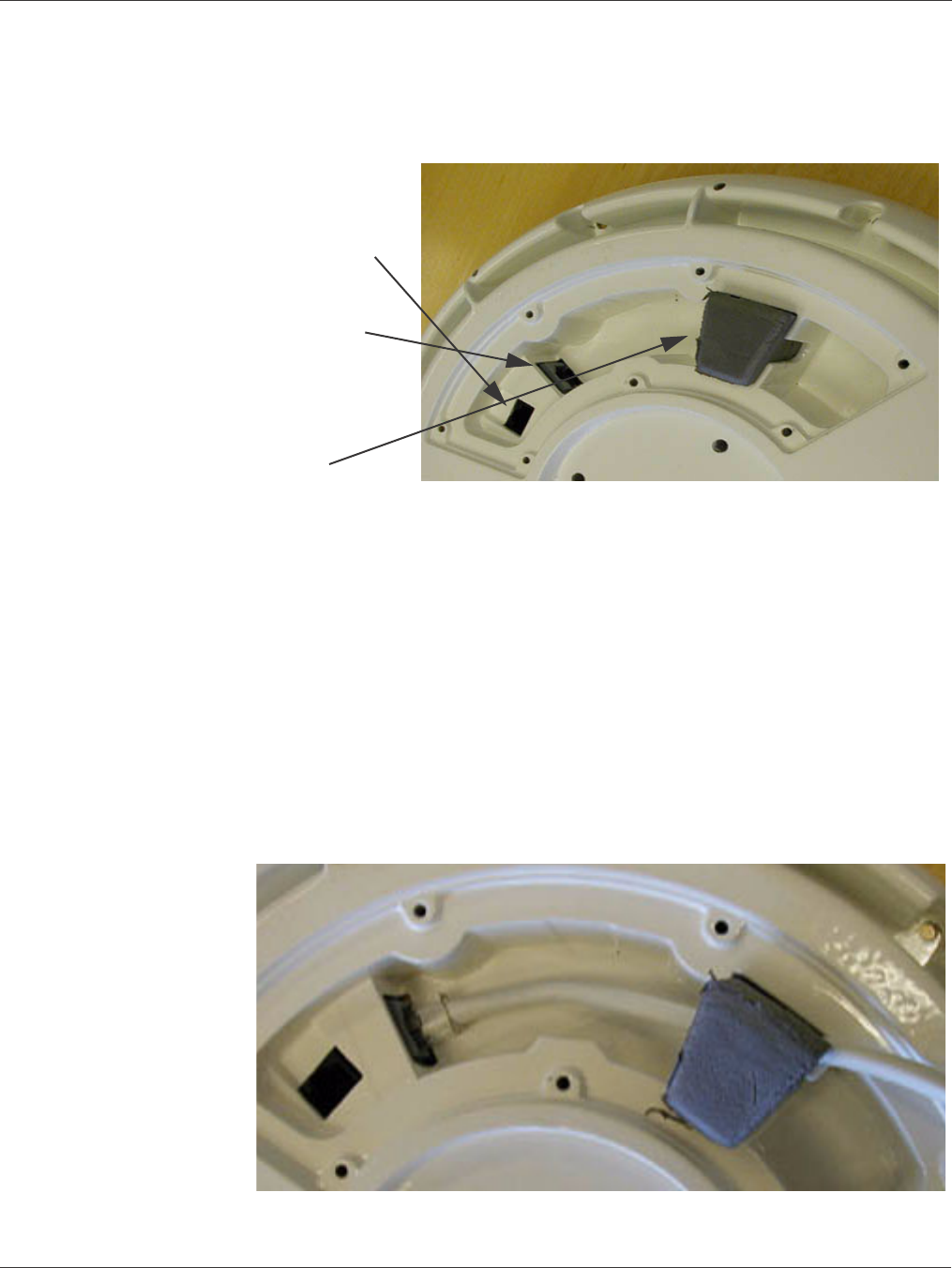
Figure 2-3 below shows the Ethernet port on the right and the serial port to
the left.
Figure 2-3 Ethernet and Serial Ports
SkyGateWay
Installation
SkyGateWay installation involves connecting the unit to the backhaul by
doing the following:
1.
Installing the Ethernet cable
2.
Installing the optional serial cable.
3.
Installing the optional serial cable adapter cover
4.
Connecting the unit to the backhaul
Install Ethernet
1.
Connect the Ethernet cable and push it into the gasket, as shown in
Figure 2-4.
Figure 2-4 Install Ethernet Cable
Serial Port
Ethernet Port
Gasket
(SkyGateWay)
SkyGateway/SkyExtender Installation And Configuration
September 2004 2-9
If you are not installing the optional serial connection, proceed to Step 5 and
then Step 9. If you are installing the optional serial connection, proceed to
Step 6.
5. Install the cover using the provided screws. The Ethernet cable is positioned to
pass through the insert in the cover, as shown in Figure 2-5.
Figure 2-5 Cover Installed
Installing Optional
Serial Adapter
Cover
If you are using a serial cable, do the following:
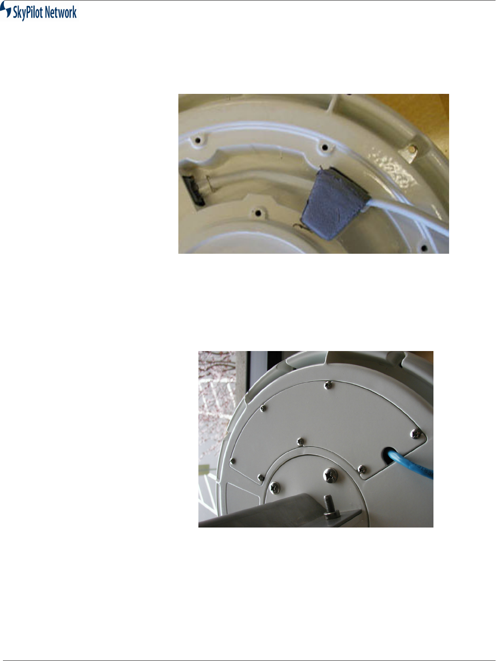
6. Thread the serial cable through the serial cable cover and slide the weather
gasket around the cable, as shown:
Figure 2-6 Connecting Serial Cable
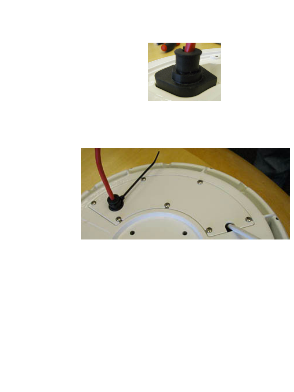
7. Fit the weather gasket down into the unit, securely surrounding the serial port,
as shown:
SkyGateway/SkyExtender Installation And Configuration Guide
2-10 September 2004
Figure 2-7 Serial Weather Gasket
8. Slide the cover down over the gasket and secure the cover using the screws
provided. Make sure the Ethernet cable passes through the insert in the cover
as shown in Figure 2-8. Use the ty-wrap to further weather-proof the gasket. Cut
the excess ty-wrap off.
Figure 2-8 Serial Adapter Cover Installation
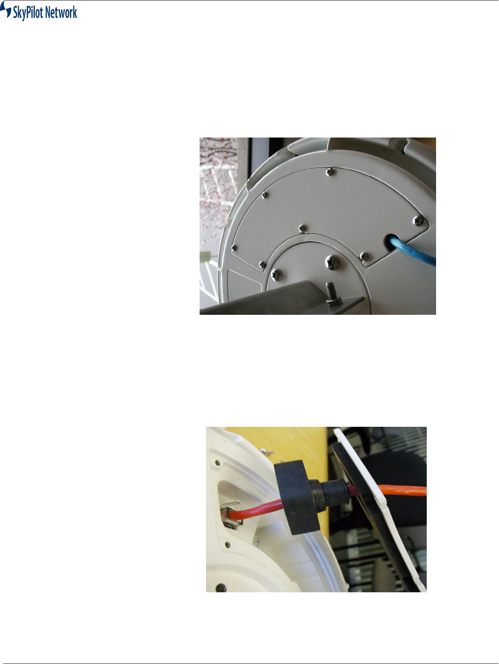
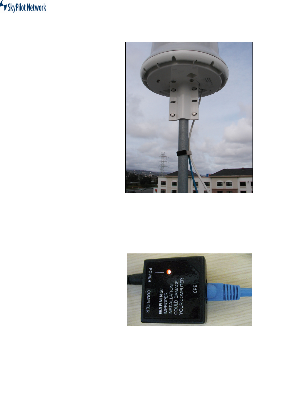
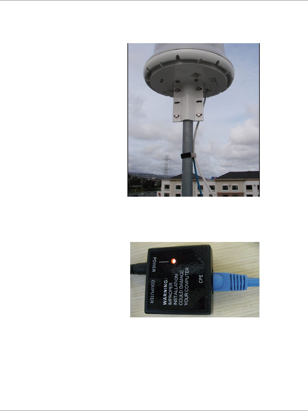
9. Secure the Ethernet cable and, if applicable, serial cable to prevent strain (par-
ticularly installations exposed to high wind conditions). Figure 2-9 shows an
example of the cable secured to the mounting pole.
SkyGateway/SkyExtender Installation And Configuration
September 2004 2-11
Figure 2-9 Secure Ethernet Cable
Powering Up
To power up the unit, perform the following steps:
1. Plug the Power Supply into a power source.
2. Connect the Ethernet cable to the
CPE
port of the Power Injector and the Power
Injector to the power supply, as shown in Figure 2-10.
Figure 2-10 Connection To Power Injector
3. Connect a second Ethernet cable from the
Computer
port of the Power Injector
to the router and the router to the T1 line.

SkyGateway/SkyExtender Installation And Configuration Guide
2-12 September 2004
Checking LEDs
Once power is on, the unit begins the boot process. The Link LED is green
and the Activity LED is yellow.
The LEDs operate as follows:
•State-Based Blinking:
- Slow blink = 4 Blinks per second;
- Fast blink = 16 Blinks per second.
•RSSI Based Blinking:
- RSSI = 0 blink/2Sec
- 0<RSSI<=10 blink/2Sec
- 10<RSSI<=20 blink/2Sec
- 20<RSSI 16 blink/2Sec
NOTE:If anything fails, refer to Chapter 3, Troubleshooting.
SkyExtender
Installation
SkyExtender installation involves the following steps:
•Installing the Ethernet cable.
•Installing the cover.
Table 2-3 : LED States
Process Link LED Activity LED
During Boot Slow Blink Slow Blink
Staggered
Boot Failed LED Off LED On
Image Inititalizing Slow Blink Slow Blink
Syncronous
Initialization Failure Initialization Failure Fast Blink
Syncronous
Initial Success but no auth LED On LED Off
SkyGateWay connected LED On LED On
SkyGateway/SkyExtender Installation And Configuration
September 2004 2-13
Install Ethernet 1. Connect the Ethernet cable and push it into the gasket. Figure 2-11
below shows this installation.
Figure 2-11 Ethernet Cable
2. Install the cover using the provided screws. The Ethernet cable is
positioned to pass through the insert in the cover, as shown in Figure
2-12.
Figure 2-12 Cover Installed
3. Secure the Ethernet cable to prevent strain (particularly installations
exposed to high wind conditions). Figure 2-13 shows an example of
the cable secured to the mounting pole.
SkyGateway/SkyExtender Installation And Configuration Guide
2-14 September 2004
Figure 2-13 Secure Ethernet Cable
Powering Up 1. Connect the Ethernet cable to the CPE Ethernet Port on the Power Injector, as
shown in Figure 2-14.
Figure 2-14 Connect To Power Injector
2. Connect the power supply to a power source and then connect it to the Power
Port of the Power Injector.
3. Connect a second Ethernet cable from the Computer port of the Power Injector
to the router and the router to the T1 line.

SkyGateway/SkyExtender Installation And Configuration
September 2004 2-15
Checking LEDs Once power is on, the unit begins the boot process. The Link LED is green
and the Activity LED is yellow.
The LEDs operate as follows:
•State-Based Blinking:
- Slow blink = 4 Blinks per second;
- Fast blink = 16 Blinks per second.
•RSSI Based Blinking:
- RSSI = 0 blink/2Sec
- 0<RSSI<=10 blink/2Sec
- 10<RSSI<=20 blink/2Sec
- 20<RSSI 16 blink/2Sec
NOTE:If anything fails, refer to Chapter 3, Troubleshooting.
Table 2-4 : LED States
Process Link LED Activity LED
During Boot Slow Blink Slow Blink
Staggered
Boot Failed LED Off LED On
Image Inititalizing Slow Blink Slow Blink
Syncronous
Initialization Failure Initialization Failure Fast Blink
Syncronous
Initial Success but no hello LED On LED Off
Heard Hello LED Off Blink Based
On RSSI
Link preauth, non-op, or op-link Slow Blink Blink Based
On RSSI
Link Standby Fast Blink Blink Based
On RSSI
SkyExtender connected LED On LED On

SkyGateway/SkyExtender Installation And Configuration Guide
2-16 September 2004
RJ-45 Pins
Serial Port
Signaling and
Cabling Using a
DB-9 Adapter
Table 2-6 shows the connecting pins for the SkyGateWay/SkyExtender’s
RJ-45 Serial Port and a standard PC Computer Serial Port.
Figure 2-15 shows the breakdown of the cabling connections.
Figure 2-15 RJ-45-to-DB-9
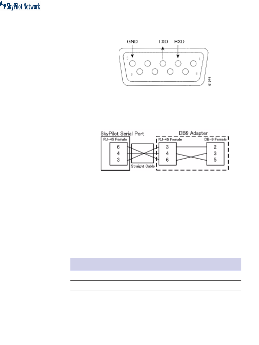
Figure 2-16 shows DB-9 pinouts.
Table 2-5 : RJ-45 Pin Assignment
Pin Assignment
1 Ethernet
2 Ethernet
3 Ethernet
4 Power
5 Power
6 Ethernet
7 Power
8 Power
Table 2-6 : RJ-45 Serial Port And PC Pins
SkyPilot SkyGateWay/
SkyExtender Console Port
PC Computer Serial Port
Signal RJ-45 Pin DB-9 Pin Signal
TxD 3 2 RxD
GND 4 5 GND
RxD 6 3 TxD
SkyGateway/SkyExtender Installation And Configuration
September 2004 2-17
Figure 2-16 DB-9 Pins
If using a straight-through cable, the connection can be visualized as
follows:
Figure 2-17 Straight-through Cabling
The key is to ensure that the colored wire inside the DB-9 adapter, which is
hard wired to Pin 3 on the RJ-45 side, is plugged into the #2 hole on the DB-
9 side, etc. SkyPilot has found that in general, the following colors in Table
2-7 can be used.
NOTE:You should verify that the wire color and connected RJ-45 pin are correct as
there is no official industry standard.
Table 2-7 : DB-9 Wire Colors
Color DB-9 Hole To Connect To
Black (Assuming RJ-45 Pin 3) 2
Yellow (Assuming RJ-45 Pin 6) 3
Red (Assuming RJ-45 Pin 4) 5

SkyGateway/SkyExtender Installation And Configuration Guide
2-18 September 2004

SkyGateway/SkyExtender/Installation And Configuration
September 2004 3-1
CHAPTER 3 TROUBLESHOOTING
This section covers problems encountered during installation and
configuration.

SkyGateway/SkyExtender/Installation And Configuration Guide
3-2 September 2004
Connecting Via a Serial Link
SkyGateway signals its presence through the use of a periodic beacon
message transmitted on the configured frequency. When a SkyExtender or
SkyConnector is installed, it listens for this network beacon message. When
a beacon is received, the SkyGateway responds and attempts to
establishment a link. In the event you need to troubleshoot the SkyGateway
from the console, perform the following steps.
1. Connect a DB-9 cable to the Serial Port.
2. Connect to a laptop.
3. Set baud settings at 38,400 and N81and run the terminal emulation
program. The unit will begin to search in a circular pattern for a nearby
SkyExtender or SkyGateway. This can take up to two minutes. Once the
unit has found a nearby SkyExtender or SkyGateway, text will starting
appearing on the screen as it outputs log messages, as shown in Figure
3-1.
Figure 3-1 Sample Screen Display
1. The main SkyPilot boot screen displays, as shown in Figure 3-2. Enter
your name and password.
sending ASB commands
asbClear: 49 unread bytes - hex dump: 31 31 31 31 31 31 31 31 31 31 31
31 31 31 31 31 31 31 31 31 31 31 31 31 31 31
31 31 31 31 31 31 31 31 31 31 31 31 31 31 31 31 31 31 31 31 31 31 31
asbClear: 1 unread bytes - hex dump: 01
0xeffdf8 (tRootTask): TS: 00:00:00:00
0xeffdf8 (tRootTask): asb.c:236 (SP_DRIVER_COMPONENT_ID)
asbSend: returned: 0xd
0xeffdf8 (tRootTask): TS: 00:00:00:00
0xeffdf8 (tRootTask): asb.c:238 (SP_DRIVER_COMPONENT_ID) 0: 0xff
0xeffdf8 (tRootTask): TS: 00:00:00:00

SkyGateway/SkyExtender/Installation And Configuration
September 2004 3-3
Figure 3-2 Login Screen Display
2. Continue installing the unit.
Welcome to SkyPilot Network, Inc.
Copyright (c) 2001, 2002, 2003 and beyond
SkyPilot login:
Password:

SkyGateway/SkyExtender/Installation And Configuration Guide
3-4 September 2004
Troubleshooting Procedures
Table 1: Troubleshooting
Problem Possible Cause Solution
LEDs do not turn on after power
connected
•No power at source
•Bad Cat5 Cable
•Bad Power Injector
•Bad Power Adapter
•Plugged into wrong port
•LEDs not functioning
•Bad unit
1) Check outlet to ensure
power
2) Double check Cat5 cable
pinout; recrimp connectors
3) Check for red LED on
Power Injector; if there is no
light, replace Power injector
4) Ensure adapter is
connected to Power Injector
and check for red LED on
Power Injector; if there is no
light, replace Power Adapter
5) Double check the Cat5
cable is connected into the
horizontal (Grey) RJ45 port; if
plugged into the vertical then
the unit has been damaged
and will need to be replaced
Double check Cat5 cable is
connected to RJ45 port on
Power Injector that is labeled
CPE and not Computer.
6) Connect straight through
Cat5 cable from Computer
port on Power Injector to
switch or hub. If you are using
a computer, connect it with an
Ethernet crossover cable;
verify Ethernet Link on switch/
hub or computer.
7) Replace unit via SkyPilot
support procedures.

SkyGateway/SkyExtender/Installation And Configuration
September 2004 3-5
SkyGateway LEDs indicate power-on
diagnostics failed (synchronous fast-
blinking LEDs)
•Diagnostics failing during
Boot process.
•Bad unit
1) Connect a PC/laptop to the
serial port and watch the unit
boot to determine at which
point unit ceases to boot;
contact SkyPilot support to
troubleshoot further.
2) Replace unit via SkyPilot
support procedures.
Cannot establish a link (Green LED
on, Yellow LED off)
•No signal reaching location
due to obstruction and/or
distance.
•Interference at similar
frequency too high in local
area and direction that unit
must be listed to receive
signal.
•Unit is in manual provision
mode and required
frequency is not in
allowable list.
•Bad unit
1) Move device to alternate
locations, changing both
elevation and position.
2) Confirm whether other
signals of similar frequencies
are present; consider
alternate frequencies if
possible.
3) Log into unit locally and
confirm frequency is in list;
add to list if missing.
4) Replace unit via SkyPilot
support procedures.
Cannot optimize a link (Greed LED off
or blinking slowly, but never begins to
blink fast)
•Insufficient signal reaching
the unit that the device is
attempting to optimize with.
•Interference at similar
frequency too high in local
area and direction of unit
that the device is
attempting to optimize with.
•Bad unit
1) Move device to alternate
locations, changing both
elevation and position.
2) Confirm whether other
signals of similar frequencies
are present at location of
remote unit; consider
alternate frequencies if
possible.
3) Replace unit via SkyPilot
support procedures.
Table 1: Troubleshooting (Continued)
Problem Possible Cause Solution

SkyGateway/SkyExtender/Installation And Configuration Guide
3-6 September 2004
Cannot authorize device (Green LED
off or blinking slowly, but never begins
to blink fast)
•Network keys are different.
•Device is set for manual
provisioning but not
configured properly.
•Device is set for auto
provisioning but is not
receiving an IP through
DHCP.
•Device is set for auto
provisioning but is not
receiving a configuration
file.
•No network connectivity to
provisioning server.
•Device is set for auto
provisioning but is
receiving incorrect
provisioning information
through its configuration
file.
•Bad unit
1) Verify Network Key on
remote unit and reset if
necessary. Configure correct
network key on device.
2) Verify needed configuration
and set through local
connection to device.
3) Verify DHCP configuration
exists and is correct. Verify
DHCP server is running.
4) Verify configuration file
exists for device and is
correct.
5) Verify requests are
reaching Provisioning Server
through log messages.
Troubleshoot network
connectivity.
6) Confirm that configuration
file contains correct settings,
such as Domain ID, allowed
frequencies, etc.
7) Replace unit via SkyPilot
support procedures.
Device is online and active in Network
but data cannot be passed from end-
user computer.
•Eth not enabled in
configuration.
•Problem with cable
between unit and end-
device
•Bad unit
1) Confirm eth state set up in
configuration.
2) Confirm there is a link on
device using show eth
command. Test cable on both
ends to confirm all copper
pairs are in place. Re-
terminate cable if needed.
3) Replace unit via SkyPilot
support procedures.
Device is active in network but cannot
be accessed
Access list on device not
configured to allow access
Confirm Access list in Node
Profile allows access from
source IP.
Table 1: Troubleshooting (Continued)
Problem Possible Cause Solution

SkyGateway/SkyExtender Installation And Configuration
September 2004 4-1
APPENDIX A SPECIFICATIONS

SkyGateway/SkyExtender Installation And Configuration Guide
4-2 September 2004
Product Specifications
Interface
Wireless 802.11a
LAN/Power RJ-45 (Power over Ethernet)
Console (SkyGateWay only) RJ-45 (RS-232 Serial Port)
Radio Characteristics
PHY standard IEEE 802.11
Operating Channels Four 20 MHz channels with 5-
MHz frequency control
WLAN Architecture SkyPilot enhanced 802.11
Media Access Control SkyPilot Synchronous Protocol
Wireless Medium 802.11a – Direct Sequence
Spread Spectrum (DSSS)
Frequency Band 5.725 - 5.825 GHz ISM
Modulation technique OFDM
Antenna Characteristics
Antenna 8 sector 16 dBi
Receive Sensitivity -90 dBm @ 6 Mbps modulation
Field of view SkyGateWay/SkyExtender/Roof
top:
8 x 45˚ horizontal x 12˚ vertical
SkyConnector Indoor/Outdoor:
30˚ horizontal x 12˚ vertical
Modulation 6-54 Mbps
EIRP 44.5 dBm
Hardware Specifications
Processor 266 MHz PowerPC
Memory 16 MB SDRAM,
16 MB Flash

SkyGateway/SkyExtender Installation And Configuration
September 2004 4-3
LEDs 2 LEDs: Wireless Activity, Wire-
less Link
Mounting tower, utility pole,
building, or other
infrastructure
Meshing yes
Antenna 360° (8 x 45∞) horizontal x 6∞
vertical, 18 dBi
Range LOS up to 20 miles (32 km)
Range near-LOS up to 4 miles (6.4 km)
Dimensions 25.0" (63.5 cm) H x 12.2" (31.0
cm) diameter (w/ mounting
bracket)
Weight 14.0 pounds (6.3 kg)
Operating temperature -40° to 131° F (-40° to 55° C)
Wind loading greater than 100 mph (161 km/h)
Enclosure/ humidity NEMA-4X
Power 24VDC; 10 Watts
Certifications FCC Part 15, FCC 47 CFR Part
15, Class B USA; compliance
with UL safety standards
EMI and susceptibility FCC Part 15.107 and 15.109
Warranty one-year limited warranty on
hardware; 90-day limited war-
ranty on software
Security
Authentication MD5-based certificates
Encryption AES
Filtering Based on protocol type, IP port
ID, and configurable IP address
list
Network Management
Command Line Interface Console via RS-232 Serial Port
or SSH

SkyGateway/SkyExtender Installation And Configuration Guide
4-4 September 2004
NMS Integration SNMP v2c
XML
GUI Configuration SkyProvision software
GUI EMS SkyControl software
IP Address DHCP or Static
Firmware Multiple versions of firmware
stored in non-volatile memory;
updated via FTP
Configuration File XML over HTTP
Quality Of Service
Prioritization 802.1p-based; also supports diff-
serv mechanism based on proto-
col type, IP port ID, and
configurable IP address list
Traffic Shaping Per-user rate limits upstream and
downstream
Monitoring & MIB Support
Supported MIBs MIB-II (RFC 1213); EtherLike
(RFC 2665); Bridge (RFC 1493);
SkyPilot private MIB
Local Management RS-232 Serial Console Port
Remote Management CLI via Telnet, SNMP 2c
Network Attributes
Architecture Layer 2
Interface Transparent bridge
802.1q VLANs
Topology
Mesh, point-to-multipoint, point-to-point