Triton Network Systems 28-ETP-FE 28 GHz Fast Ethernet Wireless Consecutive Point User Manual Installation Manual
Triton Network Systems, Inc. 28 GHz Fast Ethernet Wireless Consecutive Point Installation Manual
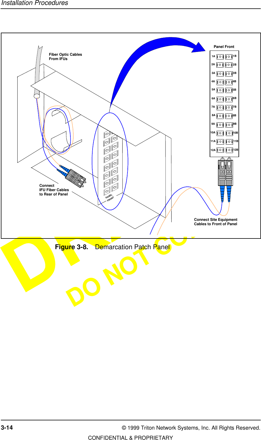
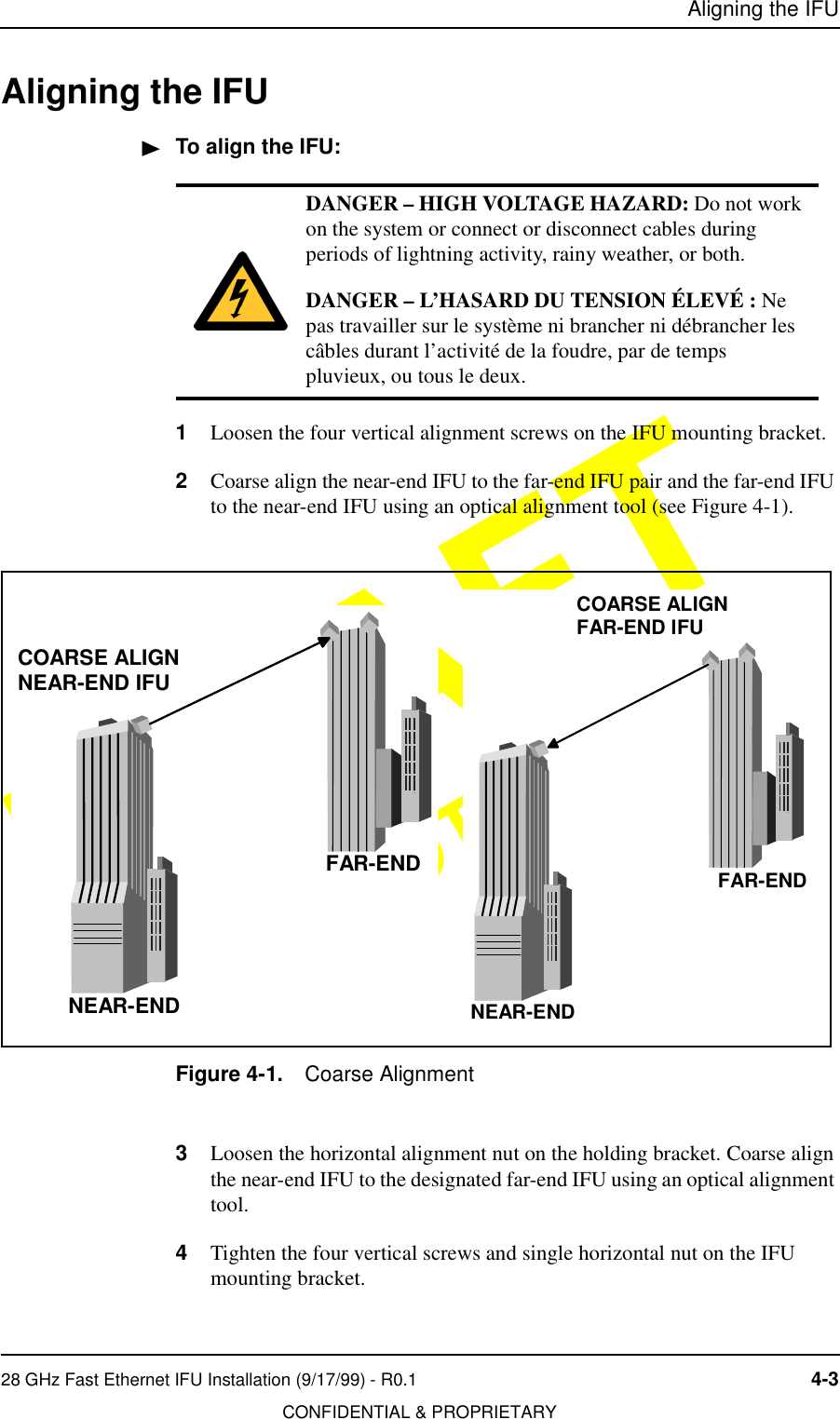
Contents
- 1. Operations Manual
- 2. Installation Manual
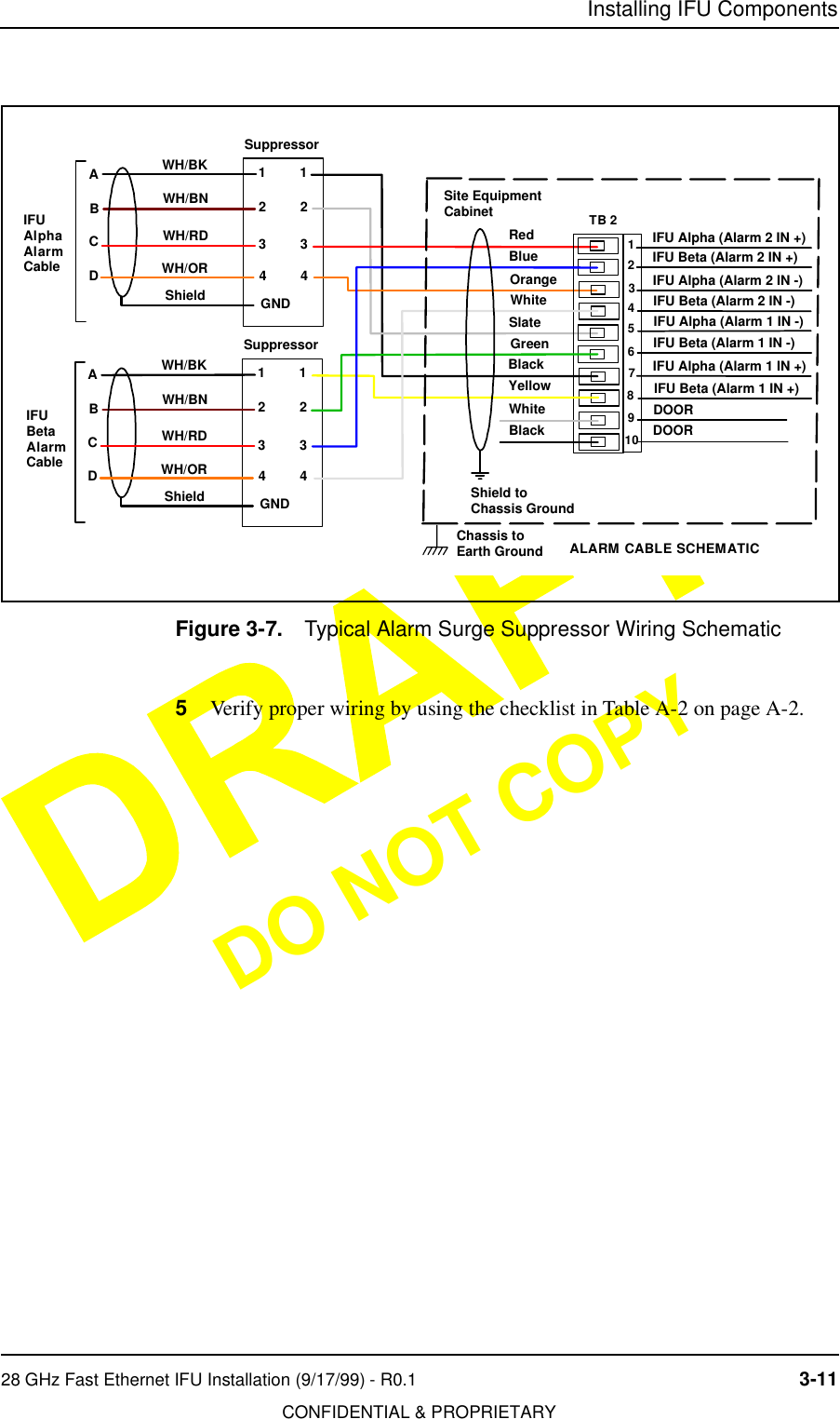
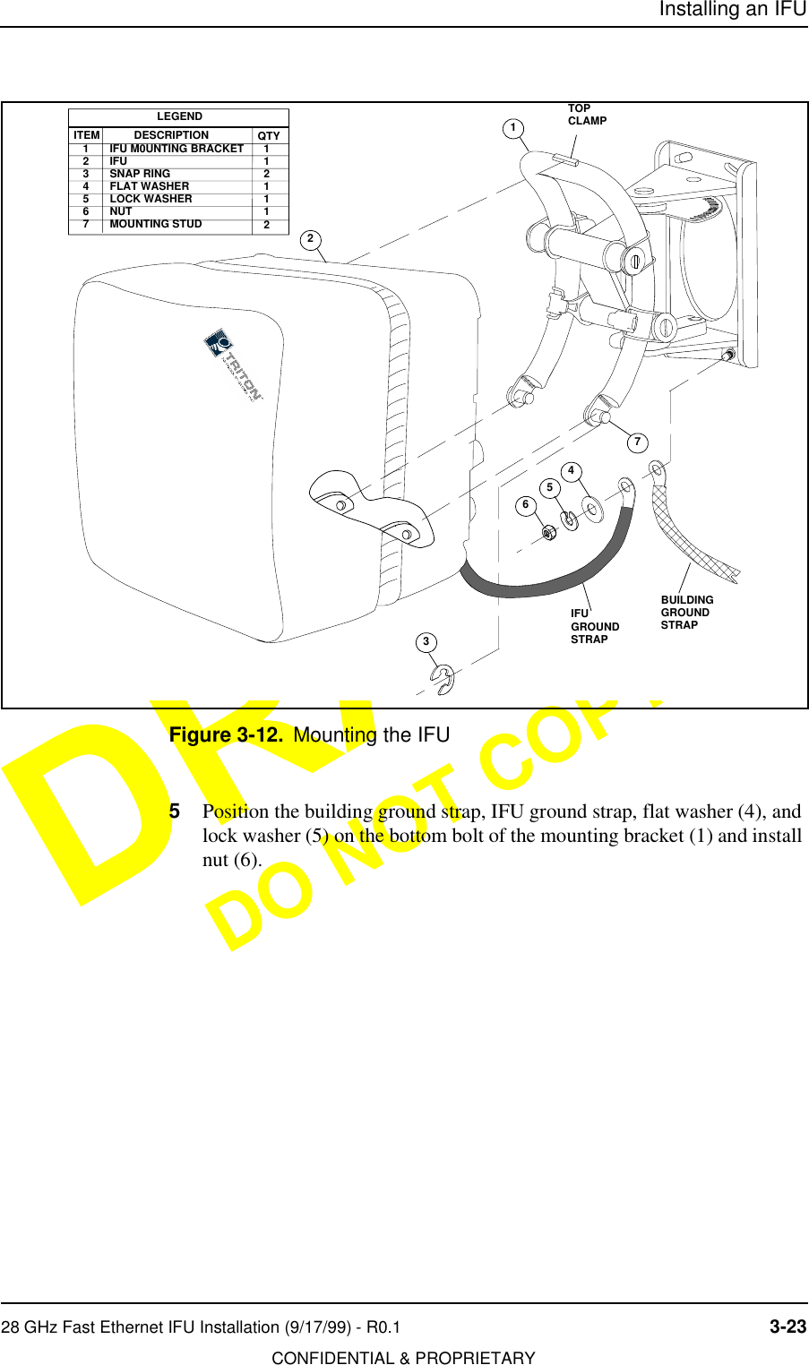
Installation Manual