Triton Network Systems 28-ETP-FE 28 GHz Fast Ethernet Wireless Consecutive Point User Manual Installation Manual
Triton Network Systems, Inc. 28 GHz Fast Ethernet Wireless Consecutive Point Installation Manual
Contents
- 1. Operations Manual
- 2. Installation Manual
Installation Manual

,QYLVLEOH)LEHU 8QLW
,QVWDOODWLRQ*XLGH

DO NOT COPY
© 1999 Triton Network Systems, Inc. All Rights Reserved.
This document and the information contained therein is the proprietary and confidential information of
Triton Network Systems, Inc. that is provided by Triton Network Systems exclusively for evaluating the
purchase of Triton Network Systems, Inc. technology and is protected by copyright and trade secret laws.
No part of this document may be disclosed, reproduced, or transmitted in any form or by any means,
electronic or mechanical, for any purpose without express written permission of Triton Network Systems,
Inc., 8529 SouthPark Circle, Orlando, FL 32819.
For permissions, contact marketing at +1-407-903-0975 or +1-407-903-0997 (FAX).
Notice of Disclaimer
The information and specifications provided in this document are subject to change without notice.
The Warranty(s) that accompany Triton Network Systems, Inc., products are set forth in the sales
agreement/contract between Triton Network Systems, Inc., and its customer. Please consult the sales
agreement for the terms and conditions of the Warranty(s) provided by Triton Network Systems, Inc.
To obtain a copy of the Warranty(s), contact Triton Network Systems, Inc., the Marketing Group at
+1-407-903-0975 or +1-407-903-0997 (FAX).
The information provided in this Triton Network Systems, Inc., document is provided “as is” without
warranty of any kind, either expressed or implied, including, but not limited to, the implied warranties of
merchantability, fitness for a particular purpose, or non-infringement. Some jurisdictions do not allow the
exclusion of implied warranties, so the above exclusion may not apply to you.
In no event shall any Triton Network Systems, Inc., company be liable for any damages whatsoever—
including special, indirect, consequential or incidental damages or damages for loss of profits, revenue,
use, or data whether brought in contract or tort, arising out of or connected with any Triton Network
Systems, Inc., Document or the use, reliance upon or performance of any material contained in or accessed
from this Triton Network Systems, Inc. document. Triton Network Systems’ license agreement may be
provided upon request. Additional Terms and Conditions will be finalized upon negotiation of a purchase.
Trademark Information
Invisible Fiber™ is a trademark of Triton Network Systems, Inc.
SmartBits™ and SmartApplication™ is a trademark of Netcom Systems Inc.
All other brand or product names are trademarks or registered trademarks of their respective companies or
organizations.
Part Number: 5035001-0002

28 GHz Fast Ethernet IFU Installation - R0.1 i
DO NOT COPY
Contents
List of Figures ......................................................................................v
List of Tables .................................................................................... vii
About This Book ............................................................................... ix
Purpose of This Book ....................................................................................ix
Intended Audience .........................................................................................ix
Format of This Book ....................................................................................... x
Conventions Used in This Book ..................................................................... x
Contacting Triton Network Systems, Inc. .....................................................xi
Warnings and Safety Guidelines ................................................... xiii
Conventions .................................................................................................xiii
Risk of Personal Injury from Electrical Shock ............................................xiv
Risk of Personal Injury from Fiber Optics ...................................................xiv
Risk of Personal Injury from Radio Frequency Energy Exposure ..............xiv
Other Risks of Personal Injury ......................................................................xv
Risk of Service Interruption .........................................................................xvi
Other Precautions ........................................................................................xvii
Avertissements et consignes de sécurité ........................................ xix
Conventions .................................................................................................xix
Risque de lésions corporelles provoquées par la décharge électrique .......... xx
Risque de lésions corporelles provoquées par les câbles à fibres
optiques ......................................................................................................... xx

ii © 1999 Triton Network Systems, Inc. All Rights Reserved.
DO NOT COPY
Risque de lésions corporelles provoquées par l’exposition de l’énergie
radiofréquences ............................................................................................xxi
Autres risques des lésions corporelles .........................................................xxi
Risque d’interruption de service .................................................................xxii
Autres mises en garde ................................................................................xxiii
Chapter 1 — Installation Overview .............................................. 1-1
Installation Overview ...................................................................................1-1
Site Engineering Folder .........................................................................1-1
IFU Link Manager .................................................................................1-2
Power Source ...............................................................................................1-2
Cabling .........................................................................................................1-2
Power Cable ..........................................................................................1-2
Alarm Cable ..........................................................................................1-2
Fiber Optic Cable ..................................................................................1-3
System Grounding and Surge Protection .....................................................1-3
Earth Ground .........................................................................................1-3
Surge Protection ....................................................................................1-3
Chapter 2 — Staging Procedure .................................................... 2-1
Configuring IFUs .........................................................................................2-1
Chapter 3 — Installation Procedures ........................................... 3-1
Setup ............................................................................................................3-2
Before Starting ......................................................................................3-2
Preparing for Installation .......................................................................3-2
Installing IFU Components ..........................................................................3-3
Mounting the IFU Bracket ....................................................................3-3
Installing Power Cables .........................................................................3-5
IFU Power Cable Test ...........................................................................3-7
Installing the Alarm Cable ....................................................................3-9
Installing the Fiber Optic Cable ..........................................................3-12
Fiber Optic Continuity Test .................................................................3-17
Installing an IFU ........................................................................................3-21

28 GHz Fast Ethernet IFU Installation - R0.1 iii
DO NOT COPY
Mounting the IFU ................................................................................3-22
Attaching IFU Cables ..........................................................................3-24
Chapter 4 — Commissioning Procedures .................................... 4-1
Setup ............................................................................................................4-2
Before Starting ......................................................................................4-2
Preparing for Installation .......................................................................4-2
Aligning the IFU ..........................................................................................4-3
Commissioning the IFU ...............................................................................4-6
Fast Ethernet Payload Test ..........................................................................4-9
Fast Ethernet Link Performance Test ........................................................4-11
Chapter 5 — Removing an IFU ..................................................... 5-1
Servicing an IFU ..........................................................................................5-2
Removing an IFU .........................................................................................5-2
Removing Cables ..................................................................................5-2
Removing an IFU from a Mounting Bracket ........................................5-4
Packing the IFU for Shipment .....................................................................5-5
Appendix A — IFU Test Results .................................................. A-1
Power Source Tests .....................................................................................A-1
Alarm Cable Verification ............................................................................A-2
Fast Ethernet Fiber Optic Test ....................................................................A-2
Far-End Test ...............................................................................................A-3
Near-End Test .............................................................................................A-3
Fast Ethernet Payload Test .........................................................................A-4
Fast Ethernet Link Performance Test .........................................................A-4
Invisible Fiber™ Product Glossary ...................................glossary-1
Index ..........................................................................................index-1

iv © 1999 Triton Network Systems, Inc. All Rights Reserved.
DO NOT COPY

28 GHz Fast Ethernet IFU Installation (9/17/99) - R0.1 v
CONFIDENTIAL & PROPRIETARY
DO NOT COPY
List of Figures
Figure 1-1. Fast Ethernet Fiber Optic Cable Configuration ...................1-4
Figure 2-1. IFU Lifting Guideline ..........................................................2-3
Figure 2-2. IFU Power Cable Hookup ...................................................2-4
Figure 2-3. Power Test Setup .................................................................2-4
Figure 2-4. IFU Configuration Setup .....................................................2-6
Figure 3-1. Example of IFU Bracket Attached to Wall ..........................3-3
Figure 3-2. Example of IFU Bracket Attached to Pole ..........................3-4
Figure 3-3. Typical Power Cable Wiring ...............................................3-6
Figure 3-4. Typical IFU Power Termination Wiring Schematic ............3-7
Figure 3-5. Power Test Setup .................................................................3-8
Figure 3-6. Typical Alarm Surge Suppressor Panel Wiring ...............3-10
Figure 3-7. Typical Alarm Surge Suppressor Wiring Schematic .........3-11
Figure 3-8. Demarcation Patch Panel ...................................................3-14
Figure 3-9. Fast Ethernet Demarcation Jumper Locations ...................3-16
Figure 3-10. Typical Fast Ethernet Site Schematic ................................3-17
Figure 3-11. Fast Ethernet Fiber Optic Continuity Test Setup ...............3-20
Figure 3-12. Mounting the IFU ..............................................................3-23
Figure 3-13. IFU Cable Connections .....................................................3-24
Figure 4-1. Coarse Alignment ................................................................4-3
Figure 4-2. Alignment Test Setup ..........................................................4-4
Figure 4-3. Fast Ethernet Payload Test Setup ........................................4-9
Figure 4-4. Fast Ethernet Link Test Setup ............................................4-11


28 GHz Fast Ethernet IFU Installation (9/17/99) - R0.1 vii
CONFIDENTIAL & PROPRIETARY
DO NOT COPY
List of Tables
Table 2-1. Typical IFU Configuration Parts List ..................................2-1
Table 3-1. Site Installation Tools ..........................................................3-2
Table 3-2. Site Installation Parts (for two IFUs) ...................................3-2
Table 3-3. Typical Power Cable Wiring ...............................................3-6
Table 3-4. Typical Alarm Surge Suppressor Panel Input Wiring .......3-10
Table 3-5. Typical Fast Ethernet Demarcation Panel Jumper
Inputs .................................................................................3-15
Table 3-6. Typical Fast Ethernet Demarcation Panel Jumper
Connections .......................................................................3-16
Table 3-7. Fast Ethernet Fiber Test Connections ................................3-21
Table 4-1. Site Commissioning Tools ...................................................4-2
Table A-1. Power Supply Test Results .................................................A-1
Table A-2. Alarm Cable Wiring Verification ........................................A-2
Table A-3. Fast Ethernet Fiber Optic Test Results ...............................A-2
Table A-4. Far-End Test Results #1 ......................................................A-3
Table A-5. Far-End Test Results #2 ......................................................A-3
Table A-6. Near-End Test Results #1 ...................................................A-3
Table A-7. Near-End Test Results #2 ...................................................A-3
Table A-8. Payload Test ........................................................................A-4
Table A-9. Link Performance Test ........................................................A-4

viii © 1999 Triton Network Systems, Inc. All Rights Reserved.
CONFIDENTIAL & PROPRIETARY
DO NOT COPY

28 GHz Fast Ethernet IFU Installation (9/17/99) - R0.1 ix
CONFIDENTIAL & PROPRIETARY
DO NOT COPY
About This Book
The Triton Network Systems, Inc., 28 GHz Invisible Fiber™ unit (IFU)
delivers high bandwidth, high-speed traffic through a wireless transport. IFUs
are configured at the factory to work with Fast Ethernet or SONET
applications. This book describes the SONET OC-3 application for the IFU.
Purpose of This Book
This book describes how to:
Configure IFUs
Perform preparatory (prior to installation) operations on an IFU, such
as downloading attributes.
Install IFUs
Install the brackets, mount the IFU, and run and connect cables.
Commission IFUs
Align IFUs and perform a series of tests to ensure proper operation.
Remove IFUs
Servicing and removing and IFU.
The procedures include required verification tests and appropriate warning
messages.
Intended Audience
This book is written specifically for installation and commissioning
technicians and network engineers. The book assumes that the reader has a
basic understanding of installing hardware.

x© 1999 Triton Network Systems, Inc. All Rights Reserved.
CONFIDENTIAL & PROPRIETARY
DO NOT COPY
Format of This Book
This book contains:
Conventions Used in This Book
This book uses the following conventions:
Italic - to indicate:
A book title
A heading or chapter title reference (for example, See
Conventions Used in This Book)
Word emphasis (for example, Do not turn on the power ....)
A Note: label to identify an informational note. For example:
NOTE: Refer to the previous chapter for more information.
For warning and safety precaution conventions, see Conventions on page xv
(English version) or Conventions on page xxi (French version).
Book Unit Description
Warnings and Safety
Guidelines on page xv
Provides a list of all warning, danger, and
caution messages related to working with IFUs.
Chapter 1, Installation
Overview Describes a typical IFU installation, the types of
cables used, and power requirements.
Chapter 2, Staging Procedure Provides the procedures to perform before
installing the IFU.
Chapter 3, Installation
Procedures
Provides the component installation procedures.
Chapter 4, Commissioning
Procedures
Provides alignment and test procedures to ensure
proper operation.
Chapter 5, Removing an IFU Provides the procedure to remove and replace an
IFU.
Appendix A, IFU Test Results Provides test forms.
Invisible Fiber™ Product
Glossary Provides descriptions of product terminology.
Index Provides an alphabetical list with the page
location of information included in this book.

28 GHz Fast Ethernet IFU Installation (9/17/99) - R0.1 xi
CONFIDENTIAL & PROPRIETARY
DO NOT COPY
Contacting Triton Network Systems, Inc.
Direct any questions to your project liaison or:
Triton Network Systems, Inc.
Technical Assistance Center (TAC)
8529 SouthPark Circle
Orlando, FL 32819
Telephone - Domestic, Toll-free: 1-877-6TRITON (1-877-687-4866)
Telephone - International: +1-407-903-2070
E-Mail: support@triton-network.com
FAX: +1-407-903-0995

xii © 1999 Triton Network Systems, Inc. All Rights Reserved.
CONFIDENTIAL & PROPRIETARY
DO NOT COPY

Warnings and Safety Guidelines (9/17/99) - R0.1 xv
CONFIDENTIAL & PROPRIETARY
DO NOT COPY
Warnings and Safety
Guidelines
Conventions
The following list identifies the warning and caution graphic symbols used in
this guide:
Risk of Personal Injury from Electrical Shock
This symbol indicates a risk of personal injury due to an
electrical shock.
Risk of Personal Injury from Fiber Optics
This symbol indicates a risk of personal injury from fiber optic
cable laser radiation.
Risk of Personal Injury from Radio Frequency Energy
Exposure
This symbol indicates a risk of personal injury due to radio
frequency energy exposure.
Other Risks of Personal Injury
This symbol indicates a risk of personal injury from a source
other than electrical shock, laser radiation, or radio frequency
energy exposure.
Risk of Service Interruption
This symbol indicates a risk of service interruption or equipment
damage.

xvi © 1999 Triton Network Systems, Inc. All Rights Reserved.
CONFIDENTIAL & PROPRIETARY
DO NOT COPY
Risk of Personal Injury from Electrical Shock
DANGER – HIGH CURRENT HAZARD: Do not turn on
power before reading the Triton Network Systems’ product
documentation. This device has a – 48 Vdc (4 amps operating
peak per feed) direct current input.
DANGER – HIGH CURRENT HAZARD: Ensure that the
– 48 Vdc power source is set to the OFF position before
beginning the installation procedures for the Invisible Fiber™
unit.
DANGER – HIGH VOLTAGE HAZARD: Do not work on
the system or connect or disconnect cables during periods of
lightning activity, rainy weather, or both.
WA RN IN G : Instructions for installing cables are intended for
licensed contractors or building maintenance personnel.
Risk of Personal Injury from Fiber Optics
DANGER: Invisible laser radiation. Avoid direct eye exposure
to the end of a fiber, fiber cord, or fiber pigtail. The infrared
light used in fiber optics systems is invisible, but can cause
serious injury to the eye.
WA RN IN G : Never touch exposed fiber with any part of your
body. Fiber fragments can enter the skin and are difficult to
detect and remove.
Risk of Personal Injury from Radio Frequency
Energy Exposure
WA RN IN G : Beware! Radio transmitter is ON when the red
light indicator on back side of Invisible Fiber™ unit is
illuminated. Observe all radio frequency energy exposure and
service interruption cautions.
WA RN IN G – RF EXPOSURE HAZARD: Ensure the safety
of all personnel. Do not stand in front of the Invisible Fiber™
unit (antenna) in order to avoid possible harmful radio
frequency energy exposure.

Other Risks of Personal Injury
Warnings and Safety Guidelines (9/17/99) - R0.1 xvii
CONFIDENTIAL & PROPRIETARY
DO NOT COPY
Other Risks of Personal Injury
NOTE: The following warning and cautions are for risk of injury
from sources other than electrical shock, fiber optics, or radio
frequency energy exposure.
WA RN IN G : This Invisible Fiber™ unit is designed to permit
the connection of the earthed conductor from the DC source
circuit to the earthing conductor at the Invisible Fiber™ unit. Do
not switch or disconnect devices in the earthed circuit conductor
between the DC source and point of connection of the earthing
electrode conductor.
WA RN IN G : Failure to follow operating instructions could
result in death or serious injury.
CAUTION: Instructions for installing cables are intended for
licensed contractors or building maintenance personnel.
CAUTION: Lifting hazard: Two people are required to lift the
Invisible Fiber™ unit. Grasp the Invisible Fiber™ unit
underneath the lower edge and lift with both hands. To prevent
injury, keep your back straight and lift with your legs, not your
back. To prevent damage to the Invisible Fiber™ unit and
components, never attempt to lift the radio by the attached
cables.
CAUTION: Keep tools and parts away from walkways. When
carrying large, heavy equipment (such as the Invisible Fiber™
unit), obstacles (such as hand tools, cables or components) may
not be easily visible and can cause accidents.

xviii © 1999 Triton Network Systems, Inc. All Rights Reserved.
CONFIDENTIAL & PROPRIETARY
DO NOT COPY
Risk of Service Interruption
CAUTION: Handle the Invisible Fiber™ unit with care to
avoid equipment damage.
CAUTION: Ensure the outside optical fiber connectors are
environmentally protected. Failure to do so may cause
contamination of the fiber surfaces.
CAUTION: The Invisible Fiber™ unit contains no owner or
user serviceable parts. Opening the radio unit or tampering with
any of its seals voids all warranties.
CAUTION: Prior to installing an Invisible Fiber™ unit, the
installation site must be surveyed to assess its appropriateness or
adequacy, system requirements, path analysis, signal path, and
power requirements.
CAUTION: Instructions for installing cables are intended for
licensed contractors or building maintenance personnel.
CAUTION: DO NOT lift the Invisible Fiber™ unit by the
Radome (front) Cover to avoid damaging the antenna.
CAUTION: Ensure the mounting bracket and Invisible Fiber™
unit are installed properly according to the instructions in the
Triton Network Systems’ product documentation.
CAUTION: Ensure that the – 48 Vdc power source is set to the
OFF position before attaching power cables to the Invisible
Fiber™ unit.
CAUTION: Do not block the front of the Invisible Fiber™ unit
to avoid possible radio service interruption.
CAUTION: To reduce the risk of fiber optic cable damage, use
the following bend radius guidelines for indoor/outdoor fiber
optic cable:
Long-term (installed): bend radius is equal to 10 times the
diameter of the cable.
Short-term (during installation): bend radius is equal to 20
times the diameter of the cable.

Other Precautions
Warnings and Safety Guidelines (9/17/99) - R0.1 xix
CONFIDENTIAL & PROPRIETARY
DO NOT COPY
Other Precautions
Failure to follow the installation procedure described in the Triton Network
Systems’ product documentation may result in damage to the Invisible
Fiber™ unit and render the unit unusable. If you have any questions, contact
your Triton Network Systems’ project liaison or the Technical Assistance
Center at:
Triton Network Systems, Inc.
8529 SouthPark Circle
Orlando, FL 32819
Telephone - Domestic, Toll-free: 1-877-6TRITON (1-877-687-4866)
Telephone - International: +1-407-903-2070
E-Mail: support@triton-network.com
FAX: +1-407-903-0995
The Invisible Fiber™ unit must be installed in accordance with wall-mount or
pole-mount specifications described in the Triton Network Systems’ product
documentation.
Observe all federal and local laws, regulations, electrical codes, building
codes, fire codes, and licensing agreements.
Ensure the safety of all personnel and bystanders from potential radio
frequency energy exposure hazards. Observe FCC 47 CFR 1.1307 for
environmental assessments, FCC 47 CFR 1.1310 for radio frequency
exposure limits, Health Canada Safety Code 6 for limits to exposure to RF
fields, and other relevant regulatory and safety compliance rules for proper
safety procedures, training, and assessment.
Ensure that appropriate warning signs are properly placed and posted at the
equipment site or access entry.
Changes or modifications to this unit not expressly approved by the party
responsible for compliance could void the user’s authority to operate the
equipment.
The equipment has been tested and found to comply with the limits for a
Class B digital device, pursuant to part 15 of the FCC rules. These limits are
designed to provide reasonable protection against harmful interference in
residential installations. This equipment generates, uses, and can radiate radio
frequency energy, and if not installed and used in accordance with the
instructions, may cause harmful interference to radio communications.
However, there is no guarantee that interference will not occur in a particular
installation. If this equipment does cause harmful interference to radio or
television reception, which can be determined by turning the equipment off
and on, the user is encouraged to try to correct the interference by performing

xx © 1999 Triton Network Systems, Inc. All Rights Reserved.
CONFIDENTIAL & PROPRIETARY
DO NOT COPY
one or more of the following measures on the radio or television antenna that
is affected by interference:
Reorient or relocate the receiving antenna.
Increase the separation between the equipment and the receiver.
Connect the equipment to an outlet on a different circuit than the
circuit the receiver is connected to.
Consult the dealer or an experienced radio or TV technician for help.
This device complies with RSS-191 of Industry Canada. Operation is subject
to the following two conditions:
This device may not cause interference
This device must accept any interference, including interference that
may cause undesired operation of the device.
This Class B digital apparatus complies with Canadian ICES-003.

Warnings and Safety Guidelines (9/17/99) - R0.1 xxi
CONFIDENTIAL & PROPRIETARY
DO NOT COPY
Avertissements et
consignes de sécurité
Conventions
La liste suivante explique les symboles d’avertissement et de mise en garde
utilisés dans ce guide:
Risque de lésions corporelles provoquées par la
décharge électrique
Ce symbole indique un risque de lésions corporelles provoquées
par la décharge électrique.
Risque de lésions corporelles provoquées par les
câbles à fibres optiques
Ce symbole indique un risque de lésions corporelles provoquées
par les câbles à fibres optiques.
Risque de lésions corporelles provoquées par
l’exposition de l’énergie radiofréquences
Ce symbole indique un risque de lésions corporelles provoquées
par l’exposition de l’énergie radiofréquences.
Autres risques de lésions corporelles
Ce symbole indique d’un risque de lésions corporelles (à part
celles provoquées par la décharge électrique, par la radiation du
laser, ou par l’exposition de l’énergie radiofréquences).
Risque d’interruption de service
Ce symbole indique un risque d’interruption de service ou de
dommage aux équipements.

xxii © 1999 Triton Network Systems, Inc. All Rights Reserved.
CONFIDENTIAL & PROPRIETARY
DO NOT COPY
Risque de lésions corporelles provoquées par la
décharge électrique
DANGER – L’HASARD DU COURANT ÉLEVÉ : Ne pas
mettre la tension avant de lire la documentation du produit
fournie par la société Triton Network Systems. Cet appareil a
une alimentation directe de – 48 V CC (courant de pointe de 4
ampères par ligne d’alimentation).
DANGER – L’HASARD DU COURANT ÉLEVÉ : S’assurer
que le bloc d’alimentation – 48 V CC est en position HORS
TENSION avant d’aborder les procédures pour l’installation de
l’unité Invisible FiberMD.
DANGER – L’HASARD DU TENSION ÉLEVÉ : Ne pas
travailler sur le système ni brancher ni débrancher les câbles
durant l’activité de la foudre, par de temps pluvieux, ou tous le
deux.
AVERTISSEMENT : Les instructions pour l’installation des
câbles sont destinées exclusivement aux entrepreneurs agréés et
aux préposés à l’entretien de l’immeuble.
Risque de lésions corporelles provoquées par les
câbles à fibres optiques
DANGER : Rayonnement laser invisible. Éviter l’exposition
directe des yeux à l’extrémité d’une fibre, d’un cordon à fibres
ou d’une fibre amorce. La lumière infrarouge utilisée dans les
systèmes à fibres optiques est invisible, mais peut provoquer des
lésions graves aux yeux.
AVERTISSEMENT : Ne jamais laisser une fibre nue entrer en
contact avec une partie quelconque du corps. Des fragments de
fibre peuvent entrer dans la peau, et sont difficiles à déceler et à
enlever.

Risque de lésions corporelles provoquées par l’exposition de l’énergie radiofréquences
Warnings and Safety Guidelines (9/17/99) - R0.1 xxiii
CONFIDENTIAL & PROPRIETARY
DO NOT COPY
Risque de lésions corporelles provoquées par
l’exposition de l’énergie radiofréquences
MISE EN GARDE : Attention ! Le poste émetteur est EN
MARCHE lorsque le témoin rouge sur le dos de l’unité Invisible
FiberMD est allumé. Respecter toutes les mises en garde
concernant l’exposition aux radiofréquences et l’interruption de
service.
MISE EN GARDE – RF EXPOSURE HAZARD : Assurer la
sécurité de tout le personnel. Ne pas rester debout devant l’unité
Invisible FiberMD (l’antenne) afin d’éviter toute exposition
dangereuse aux radiofréquences. Les lésions corporelles serieux
s’ensuivre.
Autres risques des lésions corporelles
Les mises en garde suivantes concernent les risques de lésions corporelles
attribuables à des causes autres que la décharge électrique, la radiation du
laser, ou l’exposition de l’énergie radiofréquences).
AVERTISSEMENT : Cette unité Invisible FiberMD permet la
connexion entre le conducteur de mise à la terre du circuit
d’alimentation CC et le conducteur de mise à la terre de l’unité
Invisible FiberMD. Ne pas changer ni débrancher les dispositifs
qui se trouvent dans le conducteur du circuit mis à la terre entre
la source de l’énergie CC et le point de connexion au conducteur
de l’électrode de prise de terre.
AVERTISSEMENT : Ne pas suivre les instructions
d’utilisation peut causer de sérieuses blessures et même la mort.
MISE EN GARDE : Les instructions pour l’installation des
câbles sont destinées exclusivement aux entrepreneurs agréés et
aux préposés à l’entretien de l’immeuble.
MISE EN GARDE : Danger de levage. Il faut deux personnes
pour soulever l’unité Invisible FiberMD. Saisir l’unité Invisible
FiberMD au-dessous du rebord inférieur, puis soulever l’unité
avec les deux mains. Pour éviter les lésions corporelles, garder
le dos en position verticale et soulever l’unité en utilisant les
jambes et non pas les reins. Pour éviter l’endommagement de
l’unité Invisible FiberMD et de ses composants, ne jamais essayer
de soulever la radio en tirant sur les câbles qui y sont attachés.

xxiv © 1999 Triton Network Systems, Inc. All Rights Reserved.
CONFIDENTIAL & PROPRIETARY
DO NOT COPY
MISE EN GARDE : Garder les outils et les pièces loin des
allées. Lorsqu’on transporte des équipements lourds et à grandes
dimensions (tels que l’unité Invisible FiberMD), les obstacles
(tels que les outils à main, les câbles ou les composants) sont
parfois difficiles à voir et peuvent causer des accidents.
Risque d’interruption de service
MISE EN GARDE : Manipuler l’unité Invisible FiberMD avec
soin pour éviter des dommages aux équipements.
MISE EN GARDE : S’assurer que les raccords extérieurs fibre
optique sont protégés contre l’environnement. L’absence d’une
telle protection peut entraîner la contamination des surfaces des
fibres.
MISE EN GARDE : L’unité Invisible FiberMD contient pas de
parts utilés par le propriétaire ou l’usager. Ouverture de l’unité
de la radio ou toucher aux scelles rend toute garantie nulle et
non avenue.
MISE EN GARDE : Avant d’installer une unité Invisible
FiberMD, il faut vérifier que les lieux de l’installation sont
convenables et adéquats, déterminer les besoins du système,
analyser les trajets, préciser le parcours du signal et déterminer
les exigences en matière d’énergie.
MISE EN GARDE : Les instructions pour l’installation des
câbles sont destinées exclusivement aux entrepreneurs agréés et
aux préposés à l’entretien de l’immeuble.
MISE EN GARDE : NE PAS soulever l’unité Invisible FiberMD
par le couvercle du radôme (couvercle avant), afin d’éviter
l’endommagement de l’antenne.
MISE EN GARDE : S’assurer que le support de montage et
l’unité Invisible FiberMD sont installés convenablement, selon
les instructions figurant dans la documentation du produit
fournie par la société Triton Network Systems.
MISE EN GARDE : S’assurer que le bloc d’alimentation
– 48 V CC est en position HORS TENSION avant d’attacher les
câbles d’alimentation à l’unité Invisible FiberMD.
MISE EN GARDE : Ne pas bloquer le devant de l’unité
Invisible FiberMD, pour éviter toute interruption éventuelle du
service de transmission radio.

Autres mises en garde
Warnings and Safety Guidelines (9/17/99) - R0.1 xxv
CONFIDENTIAL & PROPRIETARY
DO NOT COPY
MISE EN GARDE : Pour réduire le risque de dommage aux
câbles à fibres optiques, suivre les consignes suivantes en
matière de rayon de courbure des câbles à fibres optiques
extérieurs ou intérieurs :
Corbure à long terme (installée). Le rayon de courbure ne
doit pas dépasser 10 fois le diamètre du câble.
Courbure à court terme (pendant l’installation). Le rayon de
courbure ne doit pas dépasser 20 fois le diamètre du câble.
Autres mises en garde
L’inobservation de la procédure d’installation décrite dans la documentation
du produit fournie par la société Triton Network Systems peut endommager
l’unité Invisible FiberMD et la rendre inutilisable. Si vous avez des questions à
poser, veuillez communiquer avec votre agent de liaison des projets chez
Triton Network Systems, ou bien joindre notre Centre d’assistance technique
à l’adresse suivante :
Triton Network Systems, Inc.
8529 SouthPark Circle
Orlando, FL 32819
Téléphone - Aux États-Unis, sans frais : 1-877-6TRITON (1-877-687-4866)
Téléphone - Dans d’autres pays : +1-407-903-2070
Internet : support@triton-network.com
Télécopieur : +1-407-903-0995
Il faut installer l’unité Invisible FiberMD selon la spécification pour le montage
mural ou sur poteau, telle que précisée dans la documentation du produit
fournie par la société Triton Network Systems.
Il faut respecter l’ensemble des lois, règlements, codes d’électrique, codes du
bâtiment et codes des incendies du gouvernement fédéral et des municipalités
ainsi que tous les contrats de licence.
Assurez la sécurite de toute les personnels et les autres autour, contre l’hasard
d'exposition de l’énergie des radiofréquences. Observez FCC 47 CFR 1.1307
pour l’appréciation de l’environnement, FCC 47 CFR 1.1310 pour les
limitations d’exposition des radiofréquences, Code 6 de Sécurité de Santé
Canada pour la limite d’exposition aux champs RF, et les autre réglements
alliés et de complaisance de la sécurité pour les procédures appropriées de la
sécurité, de l’apprentissage, et de l’appréciation.
Assurez que le signals d’avertissement appropriés soivant placés
appropriatement et affichés dans la location d’équipment ou l’acces d’y
entrer.

xxvi © 1999 Triton Network Systems, Inc. All Rights Reserved.
CONFIDENTIAL & PROPRIETARY
DO NOT COPY
Cet appareil est conforme au RSS-191 de Industrie Canada. L’utilisation
dépend des deux conditions suivantes:
Cet appareil ne devrait pas causer d’interférence.
Cet appareil doit accepter toute interférence, y compris une
interférence pouvant causer une opération indésirable de l’appareil.
Cet appareil numerique de la classe B est conforme avec la norme NMB-003
du Canada.

28 GHz Fast Ethernet IFU Installation (9/17/99) - R0.1 1-1
CONFIDENTIAL & PROPRIETARY
DO NOT COPY
1Installation Overview
This chapter provides an overview of the installation procedure for the
Invisible Fiber™ unit (IFU). In addition, this chapter describes:
IFU Link Manager
Power source
Cables
System grounding and surge suppression
Installation Overview
IFUs are loaded with default system attributes at the factory. At the
customer’s designated staging area, the customer-specific attributes,
identified in the site database, are downloaded to the IFU, which is then ready
for installation. At the installation site, the IFU is installed on a mounting
bracket, aligned, and commissioned. When all installation tests are complete
and expected results are achieved on all IFU sites, the network is ready for
customer acceptance.
Site Engineering Folder
Before installing the IFU, the site must be prepared with the appropriate
cables, demarcation box, and any equipment as detailed in the site
engineering folder. (Refer to the Invisible Fiber™ Fast Ethernet Site
Evaluation Guide for details about the contents of the site engineering folder).
The site engineering folder is referenced throughout this document. Photos
and diagrams of the site are included in the folder.

Installation Overview
1-2 © 1999 Triton Network Systems, Inc. All Rights Reserved.
CONFIDENTIAL & PROPRIETARY
DO NOT COPY
IFU Link Manager
The IFU Link Manager is a local element management software application
that helps you configure and commission the IFU. You use this application to
complete the following procedures:
IFU configuration
Antenna alignment
Link commissioning tests
Power Source
The IFUs require a – 48 Vdc power source. The specifications of the power
source are defined in the site engineering folder.
Cabling
IFU installations require three types of cables:
Power
Connects the IFU to the – 48 Vdc power source.
Alarm
Connects the IFU to customer defined alarm points (customer
option).
Fiber Optic
Connects the IFU to the site equipment cabinet.
Power Cable
The power cable is outdoor/indoor rated. The power cable contains four 12
AWG conductors.
Alarm Cable
The alarm cable is outdoor/indoor rated. The alarm cable contains eight 20
AWG conductors.

System Grounding and Surge Protection
28 GHz Fast Ethernet IFU Installation (9/17/99) - R0.1 1-3
CONFIDENTIAL & PROPRIETARY
DO NOT COPY
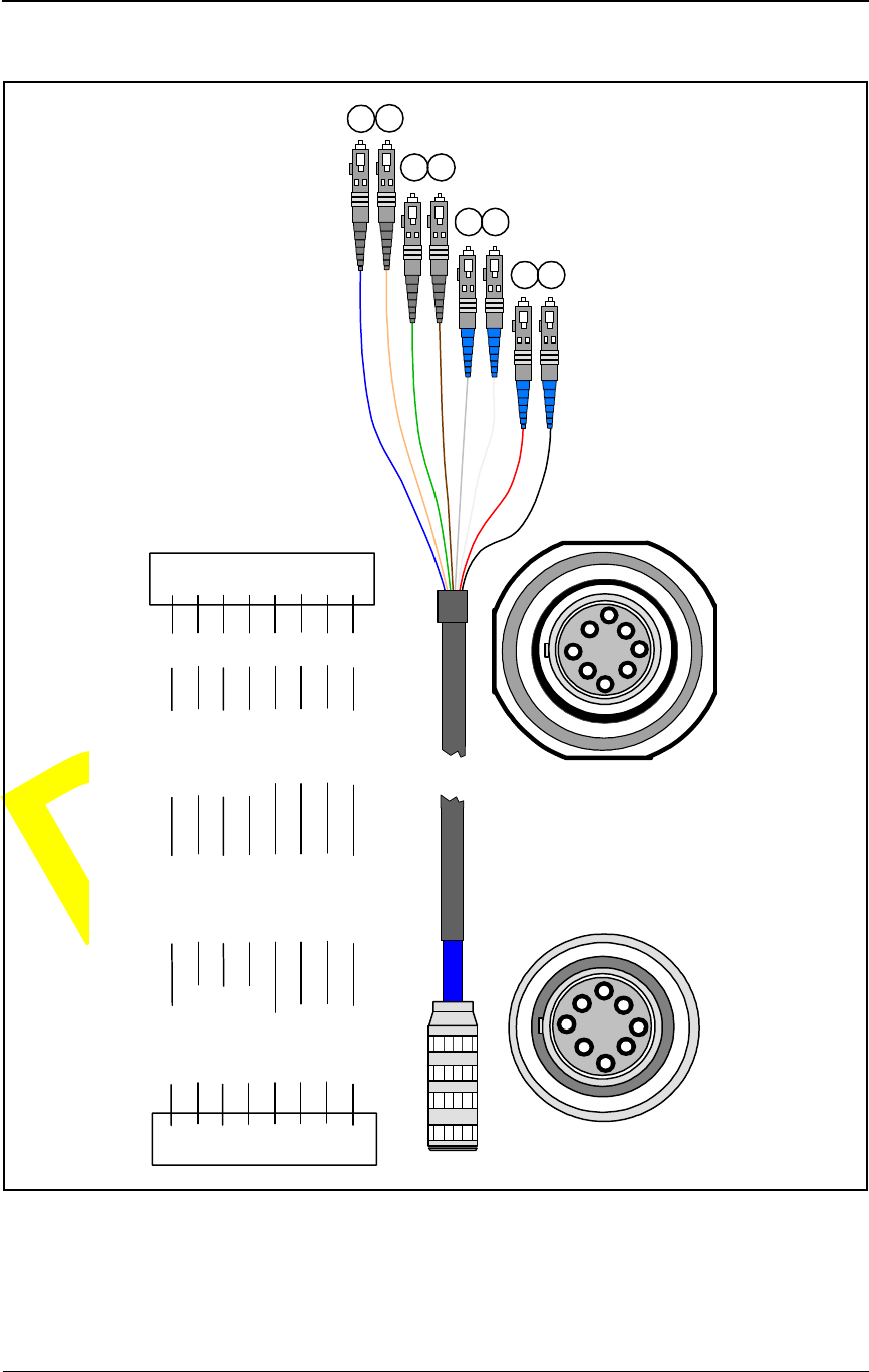
Fiber Optic Cable
For Fast Ethernet networks, the fiber optic cable (see Figure 1-1) consists of
eight multimode optical fibers. This cable connects the IFU to an indoor fiber
patch panel.
Breakout jackets provide strain relief. Each pair of fibers is connected
together from the breakout jacket to within three inches of the connector.
System Grounding and Surge Protection
The IFU grounding system has two conceptually distinct, but electrically
interconnected functional subsystems, for connection to “earth ground.” The
two functional subsystems are:
Earth ground (complies with the National Electrical Code (NEC) for
equipment grounding systems).
Surge protection.
Earth Ground
The IFU has an external electrical interconnection point for connecting the
IFU ground subsystems to earth ground.
Surge Protection
The sole purpose of surge protection is to transport lightning-related currents
to the earth ground. During site installation, surge suppression devices are
installed inline with the power and alarm conductors to assist in protecting
equipment.
Installation Overview
1-4 © 1999 Triton Network Systems, Inc. All Rights Reserved.
CONFIDENTIAL & PROPRIETARY
DO NOT COPY
Figure 1-1. Fast Ethernet Fiber Optic Cable Configuration
PLUG
CONNECTION BULKHEAD
CONNECTION
CABLE SCHEMATIC
TRITON NETWORK SYSTEMS
ETHERNET CABLE
BLUE62.5/1251310 nm
11
BLACK62.5/125 850 nm
88
ORANGE62.5/1251310 nm
22
GREEN62.5/1251310 nm
33
BROWN62.5/1251310 nm
44
SLATE62.5/125 850 nm
55
WHITE62.5/125 850 nm
66
RED62.5/125 850 nm
77
PLUGCOLORFIBER TYPEWAVE LENGTHSC
1
2
3
4
5
6
7
8
SIG
TX
TX
TX
TX
RX
RX
RX
RX
PAYLOAD
PAYLOAD
ADD/DROP
ADD/DROP
OAM&P
OAM&P
INTERCONNECT
INTERCONNECT
1
2
3
4
56
8
7
1
23
45
6
87

28 GHz Fast Ethernet IFU Installation (9/17/99) - R0.1 2-1
CONFIDENTIAL & PROPRIETARY
DO NOT COPY
2Staging Procedure
This chapter describes the IFU configuration procedure to be performed at the
designated staging area.
Configuring IFUs
IFUs are configured by using the IFU Link Manager to load the site-specific
attributes from the attributes table in the site engineering folder. Table 2-1
identifies the parts needed for configuring a typical IFU site.
Table 2-1. Typical IFU Configuration Parts List
Item
No. Description Qty.
1IFU 1
2 BNC to banana plug adapter 1
3 IFU Link Manager test cable 1
4 Laptop computer with IFU Link Manager installed 1
5 Power source (– 48 Vdc) 1
6 IFU power cable 1
7 Site engineering folder 1
8 Digital multimeter 1

Staging Procedure
2-2 © 1999 Triton Network Systems, Inc. All Rights Reserved.
CONFIDENTIAL & PROPRIETARY
DO NOT COPY
To configure each IFU, complete the following steps:
1Remove the IFU from the shipping carton and place it upright on a table
with the antenna radome cover facing away from you and the connectors
facing you. Verify that the part number on the IFU label matches the
attributes table in the site enginering folder.
22380PT-FA00 is a sample part number, where the letters are
variables defined as follows:
P = Protocol (1=SONET, 2=Ethernet)
T = Protocol type (1=OC-3, 2=OC-12, 1=Fast, 2=Gigabit)
F = Filter combination for transmit/receive (1/3=1, 2/4=2,
3/1=3, 4/2=4)
A = Antenna orientation (Vertical=1, Horizontal=2)
CAUTION: Lifting hazard: Two people are required to
lift the Invisible Fiber™ unit. Grasp the Invisible Fiber™
unit underneath the lower edge and lift with both hands.
To prevent injury, keep your back straight and lift with
your legs, not your back. To prevent damage to the
Invisible Fiber™ unit and components, never attempt to
lift the radio by the attached cables.
MISE EN GARDE : Danger de levage. Il faut deux
personnes pour soulever l’unité Invisible FiberMD. Saisir
l’unité Invisible FiberMD au-dessous du rebord inférieur,
puis soulever l’unité avec les deux mains. Pour éviter les
lésions corporelles, garder le dos en position verticale et
soulever l’unité en utilisant les jambes et non pas les reins.
Pour éviter l’endommagement de l’unité Invisible FiberMD
et de ses composants, ne jamais essayer de soulever la
radio en tirant sur les câbles qui y sont attachés.
2238011-1200
PRODUCT FREQUENCY
FILTER COMBINATION
PROTOCOL
ANTENNA ORIENTATION
PLACE HOLDER (Future)
PROTOCOL TYPE
PLACE HOLDER (Future)
PRODUCT BLOCK
Configuring IFUs
28 GHz Fast Ethernet IFU Installation (9/17/99) - R0.1 2-3
CONFIDENTIAL & PROPRIETARY
DO NOT COPY
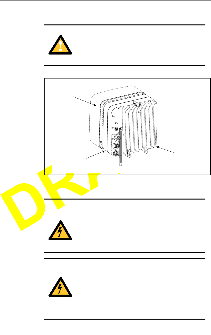
Figure 2-1. IFU Lifting Guideline
CAUTION: DO NOT lift the Invisible Fiber™ unit by the
Radome (front) Cover to avoid damaging the antenna.
MISE EN GARDE : NE PAS soulever l’unité Invisible
FiberMD par le couvercle du radôme (couvercle avant), afin
d’éviter l’endommagement de l’antenne.
DANGER – HIGH VOLTAGE HAZARD: Do not work
on the system or connect or disconnect cables during
periods of lightning activity, rainy weather, or both.
DANGER – L’HASARD DU TENSION ÉLEVÉ : Ne
pas travailler sur le système ni brancher ni débrancher les
câbles durant l’activité de la foudre, par de temps
pluvieux, ou tous le deux.
DANGER – HIGH CURRENT HAZARD: Ensure that
the – 48 Vdc power source is set to the OFF position
before beginning the installation procedures for the
Invisible Fiber™ unit.
DANGER – L’HASARD DU COURANT ÉLEVÉ :
S’assurer que le bloc d’alimentation – 48 V CC est en
position HORS TENSION avant d’aborder les procédures
pour l’installation de l’unité Invisible FiberMD.
34567
D
C
B
E
F
G
IFU
RADOME
COVER
LIFTING
AREA
LIFTING
AREA
Staging Procedure
2-4 © 1999 Triton Network Systems, Inc. All Rights Reserved.
CONFIDENTIAL & PROPRIETARY
DO NOT COPY
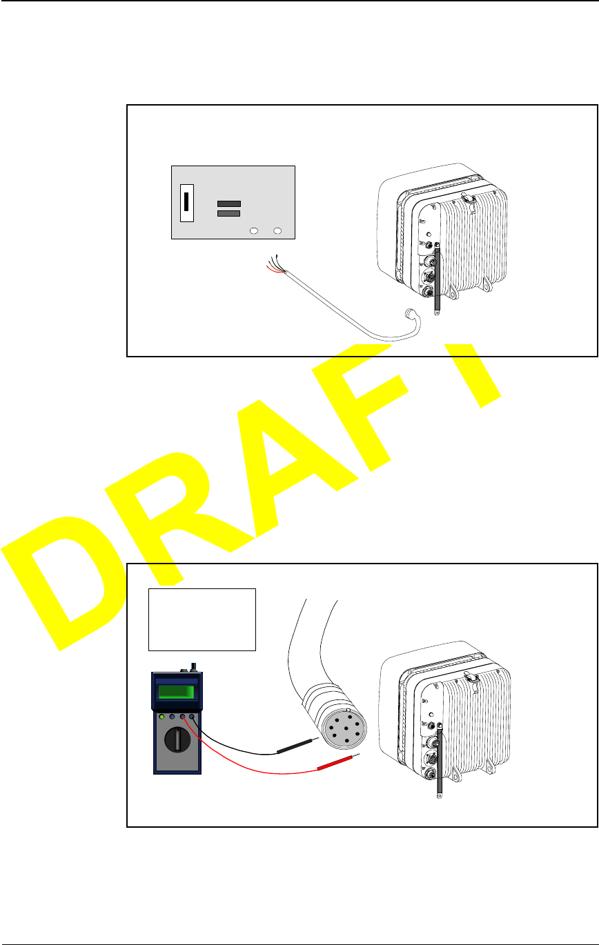
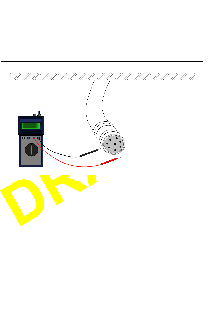
2Connect the IFU power cable to the – 48 Vdc power source as shown in
Figure 2-2.
Figure 2-2. IFU Power Cable Hookup
3Set the – 48 Vdc power source to ON.
4Set multimeter to DC voltage.
5Connect a black test lead from the negative input of the multimeter to
pin C on the IFU power cable (see Figure 2-3).
Figure 2-3. Power Test Setup
34567
D
C
B
E
F
G
IFU
POWER
CABLE
- 48 VDC POWER
SOURCE
- 48
RTN
RTN WHITE/RED (CABLE PIN C)
RTN WHITE (CABLE PIN H)
- 48 WHITE/BLACK (CABLE PIN A)
- 48 WHITE/BROWN (CABLE PIN B)
CABLE WIRE COLOR CODE
34
D
C
567
E
F
D
C
B
E
F
G
TEXT
TEXT
TEXT TE XT
TEXT TE XT
TEXT TE XT
TEXT TE XT
TEXT
TEXT
- 48
+-
MULTIMETER IFU
RTN CABLE PIN C
RTN CABLE PIN H
- 48 CABLE PIN A
- 48 CABLE PIN B
CABLE PIN ASSIGNMENT
IFU POWER
CABLE
A
E
D
C
BH
GF

Configuring IFUs
28 GHz Fast Ethernet IFU Installation (9/17/99) - R0.1 2-5
CONFIDENTIAL & PROPRIETARY
DO NOT COPY
6Connect a red test lead from the positive input of the multimeter to pin A
on the IFU power cable.
7Read the measurement on the multimeter. Passing criteria is – 46 Vdc to
– 56 Vdc.
8Connect a black test lead from the negative input of the multimeter to
pin H on the IFU power cable.
9Connect a red test lead from the positive input of the multimeter to pin B
on the IFU power cable.
10 Read the measurement on the multimeter. Passing criteria is – 46 Vdc to
– 56 Vdc.
11 Set the – 48 Vdc power source to OFF.
12 Connect – 48 Vdc power cable to the power connector on the IFU as
illustrated in Figure 2-4.
DANGER – HIGH CURRENT HAZARD: Do not turn
on power before reading the Triton Network Systems’
product documentation. This device has a – 48 Vdc
(4 amps operating peak per feed) direct current input.
DANGER – L’HASARD DU COURANT ÉLEVÉ : Ne
pas mettre la tension avant de lire la documentation du
produit fournie par la société Triton Network Systems. Cet
appareil a une alimentation directe de – 48 V CC (courant
de pointe de 4 ampères par ligne d’alimentation).
DANGER – HIGH CURRENT HAZARD: Ensure that
the – 48 Vdc power source is set to the OFF position
before beginning the installation procedures for the
Invisible Fiber™ Unit.
DANGER – L’HASARD DU COURANT ÉLEVÉ :
S’assurer que le bloc d’alimentation – 48 V CC est en
position HORS TENSION avant d’aborder les procédures
pour l’installation de l’unité Invisible FiberMD.
Staging Procedure
2-6 © 1999 Triton Network Systems, Inc. All Rights Reserved.
CONFIDENTIAL & PROPRIETARY
DO NOT COPY
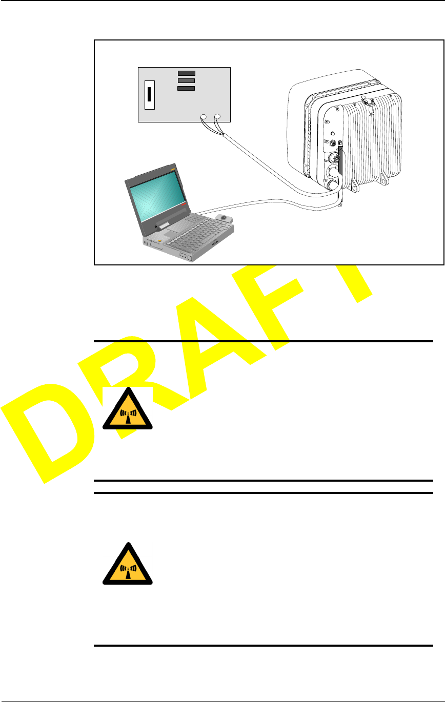
Figure 2-4. IFU Configuration Setup
13 Set the – 48 Vdc power source to ON.
WA RN IN G : Beware! Radio transmitter is ON when the
red light indicator on back side of Invisible Fiber™ unit is
illuminated. Observe all radio frequency energy exposure
and service interruption cautions.
MISE EN GARDE : Attention ! Le poste émetteur est EN
MARCHE lorsque le témoin rouge sur le dos de l’unité
Invisible FiberMD est allumé. Respecter toutes les mises en
garde concernant l’exposition aux radiofréquences et
l’interruption de service.
WA RN IN G – RF EXPOSURE HAZARD: Ensure the
safety of all personnel. Do not stand in front of the
Invisible Fiber™ unit (antenna) in order to avoid possible
harmful radio frequency energy exposure. Serious bodily
injury may result.
MISE EN GARDE – RF EXPOSURE HAZARD :
Assurer la sécurité de tout le personnel. Ne pas rester
debout devant l’unité Invisible FiberMD (l’antenne) afin
d’éviter toute exposition dangereuse aux radiofréquences.
Les lésions corporelles serieux s’ensuivre.
34567
IFU
POWER
CABLE
- 48 VDC POWER
SOURCE - 48
RTN
PC/LINK MANAGER
TEST
CABLE

Configuring IFUs
28 GHz Fast Ethernet IFU Installation (9/17/99) - R0.1 2-7
CONFIDENTIAL & PROPRIETARY
DO NOT COPY
14 Connect a laptop computer to the IFU as shown in Figure 2-4.
15 Enter the site attributes from the site database into the IFU Link Manager
program.
NOTE: Refer to IFU Link Manager help screens to enter the
required site database attributes.
16 Power down the IFU and remove the cables.
NOTE: If the staging site and the installation site are the
same place, continue with Chapter 3, Installation Procedures.
17 Confirm that the correct installation address is on the packing box and the
packing box label matches the IFU data plate, located on the back of the
IFU.
18 Use the original packing material to ship the IFU to the installation site.
Should the packing material not be available, contact Triton Network
Systems (see Contacting Triton Network Systems, Inc. on page xi) for
packing instructions.

Staging Procedure
2-8 © 1999 Triton Network Systems, Inc. All Rights Reserved.
CONFIDENTIAL & PROPRIETARY
DO NOT COPY

28 GHz Fast Ethernet IFU Installation (9/17/99) - R0.1 3-1
CONFIDENTIAL & PROPRIETARY
DO NOT COPY
3Installation Procedures
This chapter provides the procedures for installing IFU components and IFUs.
This chapter includes the following topics:
Setup
Installing IFU components
Installing an IFU
The instructions in this chapter describes the procedure for installing two
IFUs. Use the same process to install one IFU or many IFUs; the wiring
conventions are the same.
NOTE: Observe all federal and local laws, regulations,
electrical codes, building codes, fire codes, and licensing
agreements.
Il faut respecter l’ensemble des lois, règlements, codes du bâtiment
et codes des incendies du gouvernement fédéral et des municipalités
ainsi que tous les contrats de licence.
NOTE: Failure to follow the installation procedure described
in the Triton Network Systems’ product documentation may
result in damage to the Invisible Fiber™ unit and render the
unit unusable. Read through the entire installation procedure
before beginning installation.
L’inobservation de la procédure d’installation décrite dans la
documentation du produit fournie par la société Triton Network
Systems peut endommager l’unité Invisible FiberMD et la rendre
inutilisable.

Installation Procedures
3-2 © 1999 Triton Network Systems, Inc. All Rights Reserved.
CONFIDENTIAL & PROPRIETARY
DO NOT COPY
Setup
Before Starting
Before starting the procedures in this chapter, verify that all parts have been
received by checking the received items against the equipment and parts lists
in the site engineering folder.
Preparing for Installation
Table 3-1 identifies the special tools required for installation and Table 3-2
identifies the parts required.
Table 3-1. Site Installation Tools
Item
No. Description Qty.
1 Digital multimeter 1
2 Fiber cleaning kit (solution & air) 1
3 Fiber scope 1
4 Fiber tester transmitter 1
5 Fiber tester receiver 1
6 Fiber test adapter 2
7 Site engineering folder 1
8 Right-angled snap ring pliers (for external snap ring) 1
Table 3-2. Site Installation Parts (for two IFUs)
Item
No. Description Qty.
1IFU 2
2 IFU mounting bracket with snap ring kit 2
3 IFU power cable 2
4 IFU alarm cable (if specified) 2
5 Fiber optic cable 2
6 Tie-wraps, UV-rated A/R
Installing IFU Components
28 GHz Fast Ethernet IFU Installation (9/17/99) - R0.1 3-3
CONFIDENTIAL & PROPRIETARY
DO NOT COPY
Installing IFU Components
This section describes how to:
Mount the IFU bracket
Install the power cables
Install the alarm cables
Install fiber optic cables
Mounting the IFU Bracket
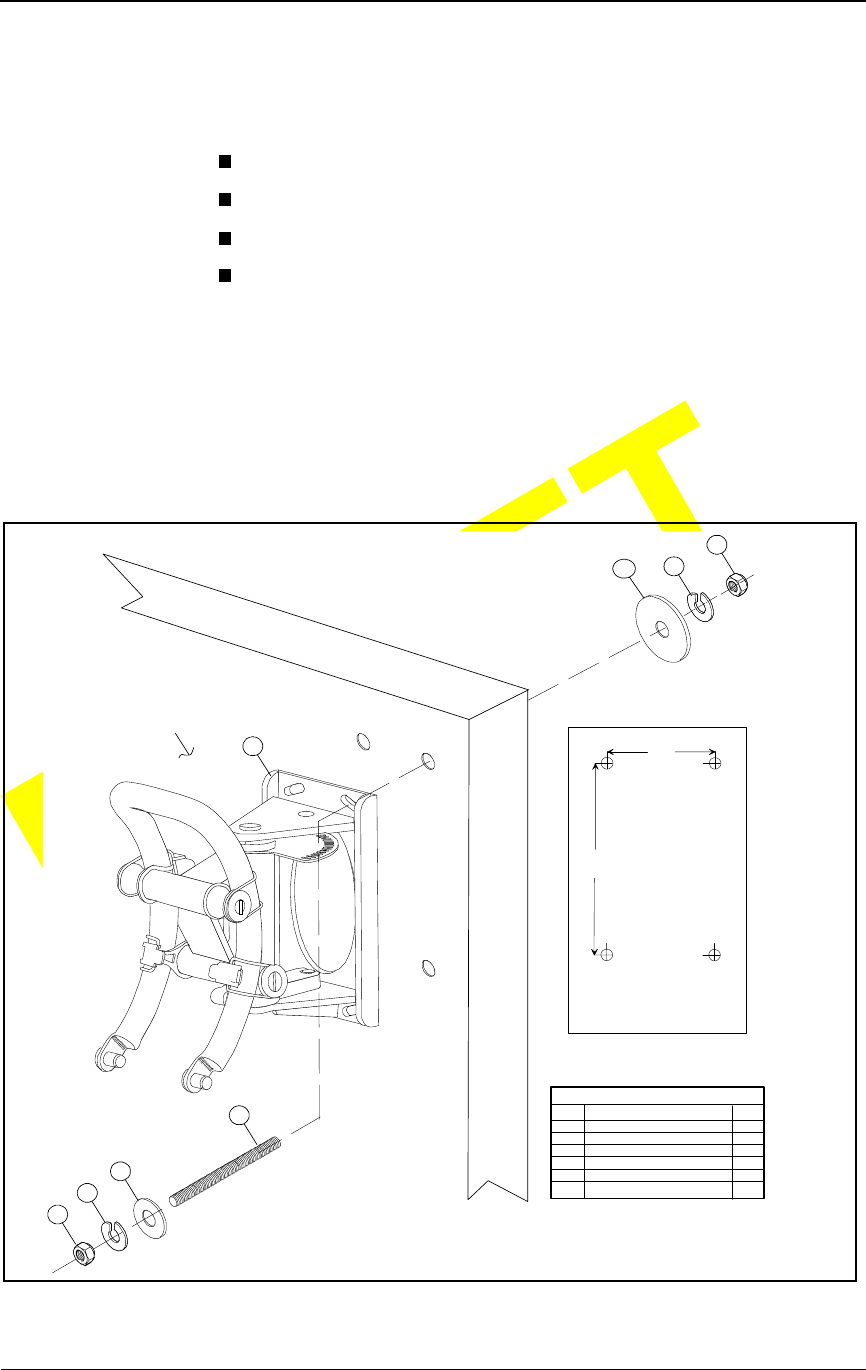
Using approved engineering methods, mount the IFU bracket in the location
specified in the site engineering folder (see Figure 3-1 for typical wall
mounting and Figure 3-2 for a typical pole mounting).
Figure 3-1. Example of IFU Bracket Attached to Wall
3
1
4
5
64
5
2
MOUNTING SURFACE
LEGEND
ITEM
1
2
3
4
5
6
DESCRIPTION
IFU M0UNTING BRACKET
THREADED ROD*
FLAT WASHER
SPLIT RING WASHER
NUT
LARGE FLATWASHER
QTY
1
4
4
8
8
4
* THREADED ROD LENGTH
IS DETERMINED BY WALL
THICKNESS PLUS 2.5 INCHES
102 MM
4.0 IN
276 MM
10.9 IN
BRACKET HOLE PATTERN
ALLOW 11MM/0.5 IN.
FOR CLEARANCE
(Not to Scale)
Installation Procedures
3-4 © 1999 Triton Network Systems, Inc. All Rights Reserved.
CONFIDENTIAL & PROPRIETARY
DO NOT COPY
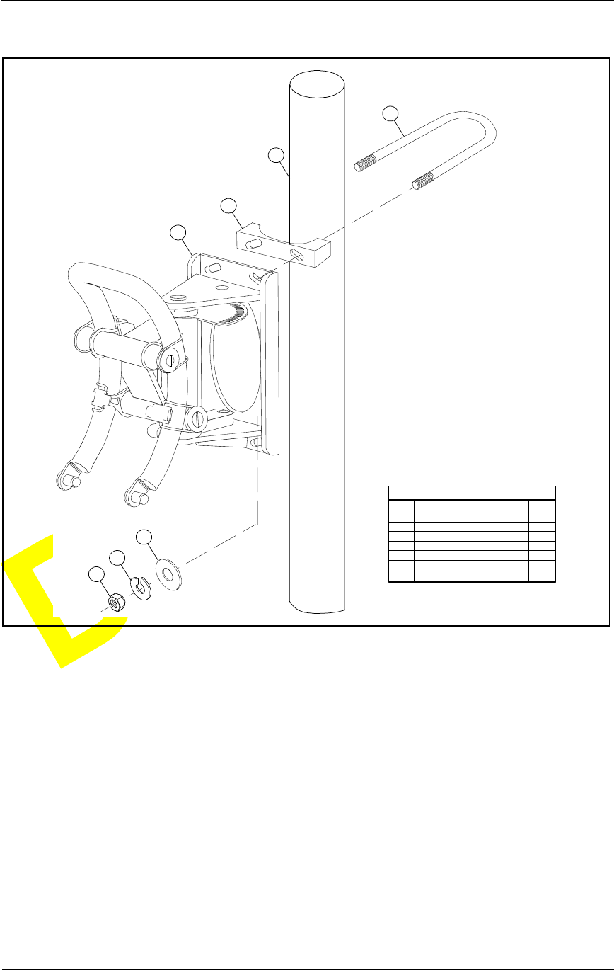
Figure 3-2. Example of IFU Bracket Attached to Pole
NOTE: Refer to the site engineering folder for location and
mount the bracket to the building or pole, using bolts as
indicated.
NOTE: Ensure the mounting bracket is mechanically stable,
plumb, and level.
LEGEND
ITEM
1
2
3
4
5
6
7
DESCRIPTION
IFU MOUNTING BRACKET
MOUNTING POLE
BRACKET
U-BOLT
FLATWASHER
LOCK WASHER
NUT
QTY
1
1
2
2
4
4
4
5
6
7
1
3
4
2

Installing IFU Components
28 GHz Fast Ethernet IFU Installation (9/17/99) - R0.1 3-5
CONFIDENTIAL & PROPRIETARY
DO NOT COPY
Installing Power Cables
There are two cable routes as follows:
The IFU Alpha power cable runs from the IFU mounting location to
the surge suppression assembly.
The IFU Beta power cable runs from the IFU mounting location to
the surge suppression assembly.
To install the IFU power cables:
1Route the IFU power cables to a surge suppression assembly according to
the site drawing.
NOTE: Allow an extra three-foot service loop at the IFU and
twelve inches at each surge suppressor. Use large radius
bends to avoid kinking the cables during the cable routing.
NOTE: Connect the cable shields to the suppressor
mounting panel. Trim the shield back to the cable breakout
and keep the shield as short as possible.
2Trim each cable to the appropriate length.
3Strip each cable wire to 3/8 inch and tin.
4Attach the IFU power cables to the surge suppressors as shown on
Figure 3-3, Figure 3-4, and Table 3-3.
DANGER – HIGH VOLTAGE HAZARD: Do not work
on the system or connect or disconnect cables during
periods of lightning activity, rainy weather, or both.
DANGER – L’HASARD DU TENSION ÉLEVÉ : Ne
pas travailler sur le système ni brancher ni débrancher les
câbles durant l’activité de la foudre, par de temps
pluvieux, ou tous le deux.
CAUTION: Instructions for installing cables are intended
for licensed contractors or building maintenance
personnel.
MISE EN GARDE : Les instructions pour l’installation
des câbles sont destinées exclusivement aux entrepreneurs
agréés et aux préposés à l’entretien de l’immeuble.
Installation Procedures
3-6 © 1999 Triton Network Systems, Inc. All Rights Reserved.
CONFIDENTIAL & PROPRIETARY
DO NOT COPY
Figure 3-3. Typical Power Cable Wiring
IFU Alpha
Suppressor
IFU Beta
Suppressor
IFU Beta Power Cable
White
(PB-2)
IFU Alpha Power Cable
White/Black
(PA-4)
White/Brown
(PA-3)
White/Red
(PA-1)
Protected
Shield
-+-+
White
(PA-2) White/Red
(PB-1)
White/Black
(PB-4)
White/Brown
(PB-3)
Shield
Protected
Surge Surge
Table 3-3. Typical Power Cable Wiring
IFU Alpha
Surge Input Wire Color/
Number IFU Beta
Surge Input Wire Color/
Number
RTN (+) White (PA-2),
White/Red (PA-1)
RTN (+) White (PB-2),
White/Red (PB-1)
– 48 (–) White/Black (PA-4),
White/Brown (PA-3)
– 48 (–) White/Black (PB-4),
White/Brown (PB-3)
Installing IFU Components
28 GHz Fast Ethernet IFU Installation (9/17/99) - R0.1 3-7
CONFIDENTIAL & PROPRIETARY
DO NOT COPY
Figure 3-4. Typical IFU Power Termination Wiring Schematic
IFU Power Cable Test
To ensure proper wiring, perform the input power test on both IFU power
cables prior to connecting to the IFU. This test ensures that the input power to
the IFU is between – 46 Vdc and – 56 Vdc.
To test the power cable:
RTN
WH (PA-2)
A
IFU
Alpha
Power
Cable
WH/BK (PA-4)
B
- 48
Vdc
WH/BN (PA-3)
CWH/RD (PA-1)
H
Suppressor
GND
Shield
RTN
IFU
Beta
Power
Cable - 48
Vdc
GND
Shield
F1 Conn
++
-
Power
Source
F1
Common Bar
F2
Common Bar
F2 Conn
Shield to
Chassis Ground
Site Equipment
Cabinet
Surge
Protected
Protected
Surge
+
+
+
+
--
--
-
-
-
White (PB-2)
Brown (PB-3)
Black (PA-4)
Red (PA-1)
White
Red
Brown
Black
++
A
B
C
HWH (PB-2)
WH/BK (PB-4)
WH/BN (PB-3)
WH/RD (PB-1)
Chassis to
Earth Ground
Panel to
Earth Ground
DANGER – HIGH VOLTAGE HAZARD: Do not work
on the system or connect or disconnect cables during
periods of lightning activity, rainy weather, or both.
DANGER – L’HASARD DU TENSION ÉLEVÉ : Ne
pas travailler sur le système ni brancher ni débrancher les
câbles durant l’activité de la foudre, par de temps
pluvieux, ou tous le deux.
Installation Procedures
3-8 © 1999 Triton Network Systems, Inc. All Rights Reserved.
CONFIDENTIAL & PROPRIETARY
DO NOT COPY
1Set the – 48 Vdc power source to ON.
2Set multimeter to DC voltage.
3At the mounting location, connect a black test lead from the negative
input of the multimeter to pin C on the power cable (see Figure 3-5).
Figure 3-5. Power Test Setup
4Connect a red test lead from the positive input of the multimeter to
pin A on the power cable. Record the results in Table A-1 on page A-1.
5Read the measurement on the multimeter. Passing criteria is – 46 Vdc to
– 56 Vdc. Record the results in Table A-1 on page A-1.
6Connect a black test lead from the negative input of the multimeter to
pin H on the power cable.
7Connect a red test lead from the positive input of the multimeter to pin B
on the power cable.
8Read the measurement on the multimeter. Passing criteria is – 46 Vdc to
– 56 Vdc. Record the results in Table A-1 on page A-1.
Repeat the above test for each IFU power cable.
OUTSIDE
INSIDE
IFU POWER
CABLE
RTN CABLE PIN C
RTN CABLE PIN H
- 48 CABLE PIN A
- 48 CABLE PIN B
CABLE PIN ASSIGNMENT
A
E
D
C
BH
GF
TEXT
TEXT
TEXT TEXT
TEXT TEXT
TEXT TEXT
TEXT TEXT
TEXT
TEXT
- 48
+-
MULTIMETER

Installing IFU Components
28 GHz Fast Ethernet IFU Installation (9/17/99) - R0.1 3-9
CONFIDENTIAL & PROPRIETARY
DO NOT COPY
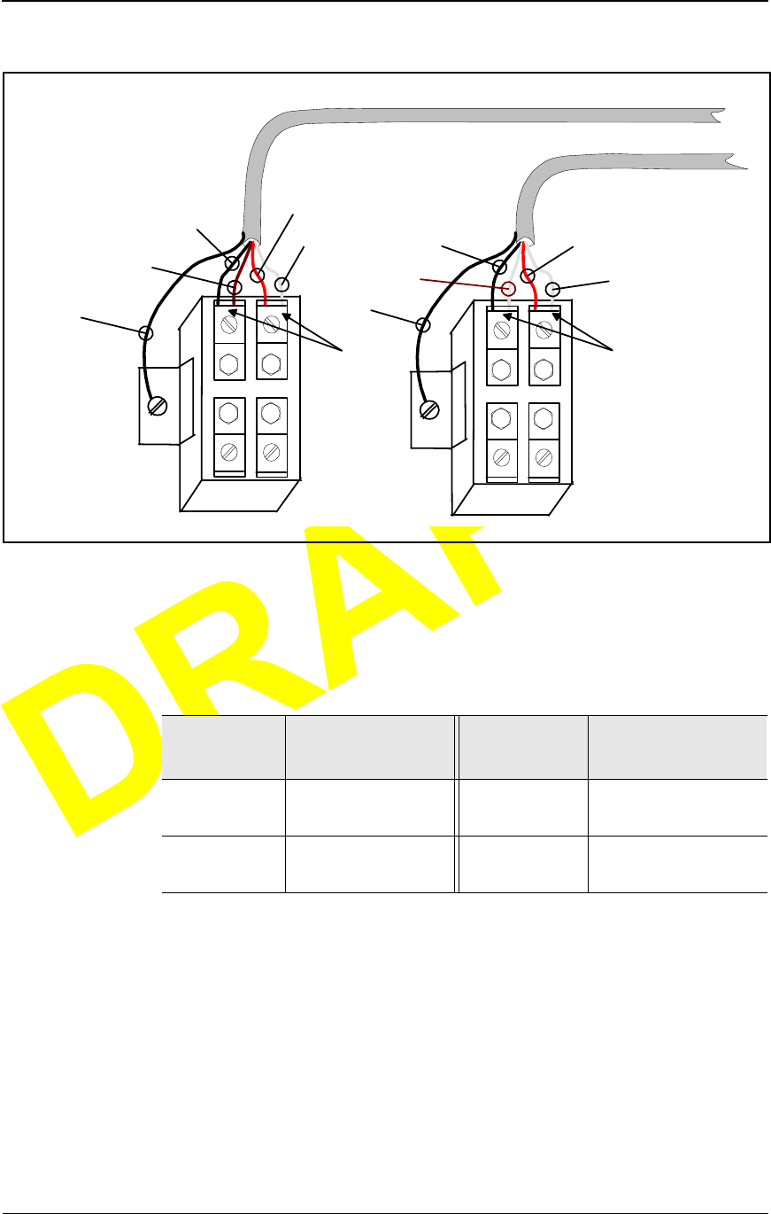
Installing the Alarm Cable
There are two cable routes as follows:
The IFU Alpha alarm cable runs from the IFU mounting location to
the surge suppression assembly.
The IFU Beta alarm cable runs from the IFU mounting location to the
surge suppression assembly.
To install the alarm cable:
1Route the IFU alarm cable to the alarm surge suppressors according to the
site drawing in the site engineering folder.
NOTE: Allow an extra three-foot service loop at IFU and
twelve inches at each surge suppressor. Use large radius
bends to avoid crimping and kinking the cables during the
cable routing.
NOTE: Connect the cable shield to the suppressor ground
lug. Trim the shield back to the cable breakout and keep the
shield as short as possible.
2Trim each cable to the appropriate length.
3Strip each cable wire to 3/8 inch and tin.
4Attach IFU alarm cables to the suppressors. Figure 3-6, Figure 3-7, and
Table 3-4 show a sample layout.
Installation Procedures
3-10 © 1999 Triton Network Systems, Inc. All Rights Reserved.
CONFIDENTIAL & PROPRIETARY
DO NOT COPY
Figure 3-6. Typical Alarm Surge Suppressor Panel Wiring
IFU Beta
Alarm Surge
Supperssor
1
11
1
2
22
23
3
33
4
4
4
4
IFU Beta Alarm Cable
WHITE/ORANGE
WHITE/BLACK
IFU Alpha Alarm Cable
WHITE/BLACK
WHITE/BROWN
WHITE/RED WHITE/BROWN
WHITE/RED
WHITE/ORANGE
SHIELD SHIELD
Lines
Equipment
Lines
Equipment
IFU Alpha
Alarm Surge
Supperssor
Table 3-4. Typical Alarm Surge Suppressor Panel Input Wiring
Alarm
Suppressor
IFU Alpha
Wire Color/
Connector Pin
Alarm
Suppressor
IFU Beta
Wire Color/
Connector Pin
1 (line) White/Black (A) 1 (line) White/Black (A)
2 (line) White/Brown (B) 2 (line) White/Brown (B)
3 (line) White/Red (C) 3 (line) White/Red (C)
4 (line) White/Orange (D) 4 (line) White/Orange (D)
Installing IFU Components
28 GHz Fast Ethernet IFU Installation (9/17/99) - R0.1 3-11
CONFIDENTIAL & PROPRIETARY
DO NOT COPY
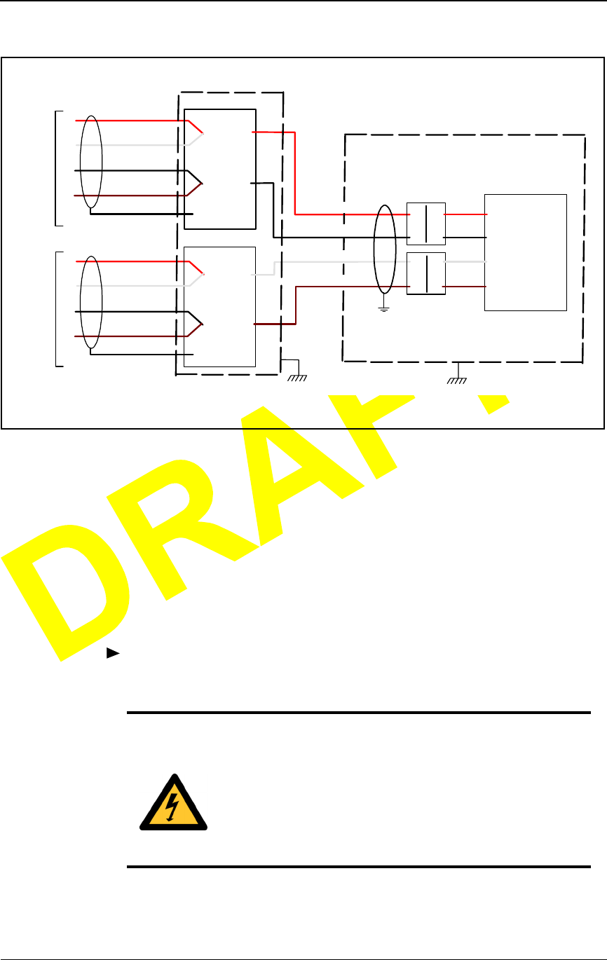
Figure 3-7. Typical Alarm Surge Suppressor Wiring Schematic
5Verify proper wiring by using the checklist in Table A-2 on page A-2.
A
IFU
Alpha
Alarm
Cable
WH/BK
BWH/BN
CWH/RD
D
Suppressor
GND
Shield
1
1
2
3
4
5
6
7
8
9
10
TB 2
1
22
33
44
WH/OR
A
IFU
Beta
Alarm
Cable
WH/BK
BWH/BN
CWH/RD
D
Suppressor
GND
Shield
1 1
22
33
44
WH/OR
IFU Alpha (Alarm 2 IN +)
IFU Beta (Alarm 2 IN +)
IFU Alpha (Alarm 2 IN -)
IFU Beta (Alarm 2 IN -)
IFU Alpha (Alarm 1 IN -)
IFU Beta (Alarm 1 IN -)
DOOR
ALARM CABLE SCHEMATIC
Shield to
Chassis Ground
Site Equipment
Cabinet
IFU Alpha (Alarm 1 IN +)
IFU Beta (Alarm 1 IN +)
DOOR
Chassis to
Earth Ground
Black
Yellow
Green
Slate
White
Orange
Red
Blue
White
Black

Installation Procedures
3-12 © 1999 Triton Network Systems, Inc. All Rights Reserved.
CONFIDENTIAL & PROPRIETARY
DO NOT COPY
Installing the Fiber Optic Cable
There are two fiber optic cable routes as follows:
The IFU Alpha fiber optic cable runs from the IFU mounting location
to the site equipment cabinet.
The IFU Beta fiber optic cable runs from the IFU mounting location
to the site equipment cabinet.
To install the fiber optic cable:
WA RN IN G : Never touch exposed fiber with any part of
your body. Fiber fragments can enter the skin and are
difficult to detect and remove.
AVERTISSEMENT : Ne jamais laisser une fibre nue
entrer en contact avec une partie quelconque du corps. Des
fragments de fibre peuvent entrer dans la peau, et sont
difficiles à déceler et à enlever.
DANGER: Invisible laser radiation. Avoid direct eye
exposure to the end of a fiber, fiber cord, or fiber pigtail.
The infrared light used in fiber optics systems is invisible,
but can cause serious injury to the eye.
AVERTISSEMENT : Rayonnement laser invisible.
Éviter l’exposition directe des yeux à l’extrémité d’une
fibre, d’un cordon à fibres ou d’une fibre amorce. La
lumière infrarouge utilisée dans les systèmes à fibres
optiques est invisible, mais peut provoquer des lésions
graves aux yeux.
CAUTION: Ensure the outside optical fiber connectors
are environmentally protected. Failure to do so may cause
contamination of the fiber surfaces.
MISE EN GARDE : S’assurer que les raccords extérieurs
fibre optique sont protégés contre l’environnement.
L’absence d’une telle protection peut entraîner la
contamination des surfaces des fibres.

Installing IFU Components
28 GHz Fast Ethernet IFU Installation (9/17/99) - R0.1 3-13
CONFIDENTIAL & PROPRIETARY
DO NOT COPY
1Route the IFU fiber optic cables from each of the IFU mounting locations
to the site equipment cabinet. Refer to the site drawing in the site
engineering folder for the specific route.
NOTE: Allow an extra three-foot service loop at both ends.
Use large radius bends to avoid crimping and kinking the
cables during the cable routing.
2Connect the IFU fiber optic cables to the rear side of the patch panel as
shown in Figure 3-8 and Table 3-5.
CAUTION: To reduce the risk of fiber optic cable
damage, use the following bend radius guidelines for
indoor/outdoor fiber optic cable:
Long-term (installed): bend radius is equal to 10 times
the diameter of the cable.
Short-term (during installation): bend radius is equal to
20 times the diameter of the cable.
MISE EN GARDE : Pour réduire le risque de dommage
aux câbles à fibres optiques, suivre les consignes suivantes
en matière de rayon de courbure des câbles à fibres
optiques extérieurs ou intérieurs :
Courbure à long terme (installée). Le rayon de courbure
ne doit pas dépasser 10 fois le diamètre du câble.
Courbure à court terme (pendant l’installation). Le
rayon de courbure ne doit pas dépasser 20 fois le
diamètre du câble.
Installation Procedures
3-14 © 1999 Triton Network Systems, Inc. All Rights Reserved.
CONFIDENTIAL & PROPRIETARY
DO NOT COPY
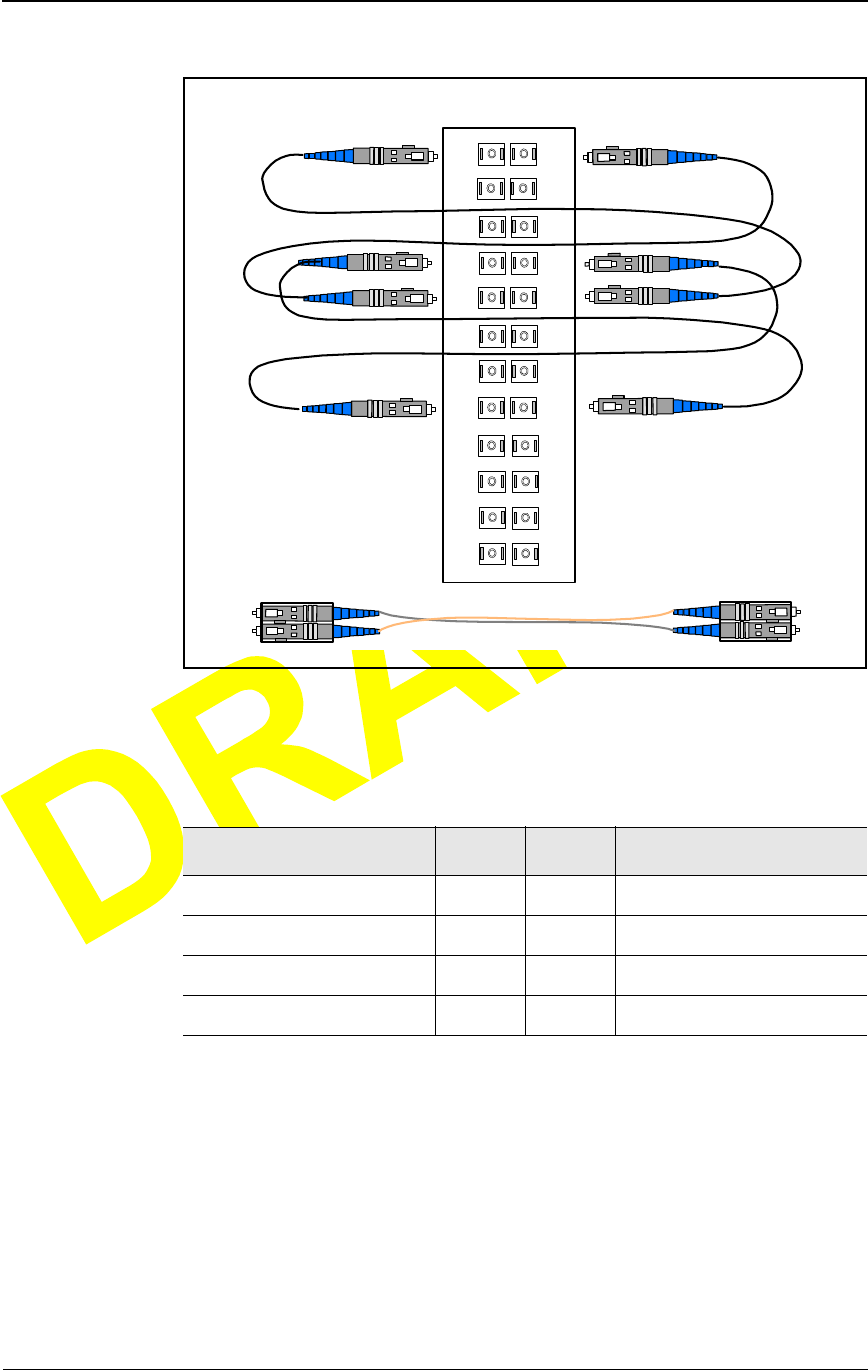
Figure 3-8. Demarcation Patch Panel
1A 1B
2A 2B
3A 3B
4A
5A
4B
5B
6A 6B
7A 7B
8A
9B
8B
9A
10A 10B
11A 11B
12A 12B
Fiber Optic Cables
From IFUs
Connect
IFU Fiber Cables
to Rear of Panel
Panel Front
Connect Site Equipment
Cables to Front of Panel
PANEL
FRONT

Installing IFU Components
28 GHz Fast Ethernet IFU Installation (9/17/99) - R0.1 3-15
CONFIDENTIAL & PROPRIETARY
DO NOT COPY
3Connect the jumpers to the front of the demarcation patch panel as shown
in Figure 3-9, Table 3-6, and Figure 3-10.
Table 3-5. Typical Fast Ethernet Demarcation Panel Jumper Inputs
Fiber Function Fiber
Color/Number
Rear of
Demarcation
Panel Fiber Type
IFU Alpha
Payload TX Blue (FA-1) 1A 100BaseFX
Payload RX Orange (FA-2) 1B 100BaseFX
Add/Drop TX Green (FA-3) 2A 100BaseFX
Add/Drop RX Brown (FA-4) 2B 100BaseFX
OAM&P TX Slate (FA-5) 3A 10BaseFL
OAM&P RX White (FA-6) 3B 10BaseFL
Interconnect TX Red (FA-7) 4A 10BaseFL
Interconnect RX Black (FA-8) 4B 10BaseFL
IFU Beta
Payload TX Blue (FB-1) 5A 100BaseFX
Payload RX Orange (FB-2) 5B 100BaseFX
Add/Drop TX Green (FB-3) 6A 100BaseFX
Add/Drop RX Brown (FB-4) 6B 100BaseFX
OAM&P TX Slate (FB-5) 7A 10BaseFL
OAM&P RX White (FB-6) 7B 10BaseFL
Interconnect TX Red (FB-7) 8A 10BaseFL
Interconnect RX Black (FB-8) 8B 10BaseFL
Installation Procedures
3-16 © 1999 Triton Network Systems, Inc. All Rights Reserved.
CONFIDENTIAL & PROPRIETARY
DO NOT COPY
Figure 3-9. Fast Ethernet Demarcation Jumper Locations
NOTE: *Jumpers not required for a gateway site.
Table 3-6. Typical Fast Ethernet Demarcation Panel Jumper
Connections
Fiber Function From* To* Fiber Function
IFU Alpha Payload TX 1A 5B IFU Beta Payload RX
IFU Alpha Payload RX 1B 5A IFU Beta Payload TX
IFU Alpha Interconnect TX 4A 8B IFU Beta Interconnect RX
IFU Alpha Interconnect RX 4B 8A IFU Beta Interconnect TX
Panel Front
Triton Supplied
Jumper Pairs are
Configured with
Crossover
Demarcation
1A 1B
2A 2B
3A 3B
4A
5A
4B
5B
6A 6B
7A 7B
8A
9B
8B
9A
10A 10B
11A 11B
12A 12B
Installing IFU Components
28 GHz Fast Ethernet IFU Installation (9/17/99) - R0.1 3-17
CONFIDENTIAL & PROPRIETARY
DO NOT COPY
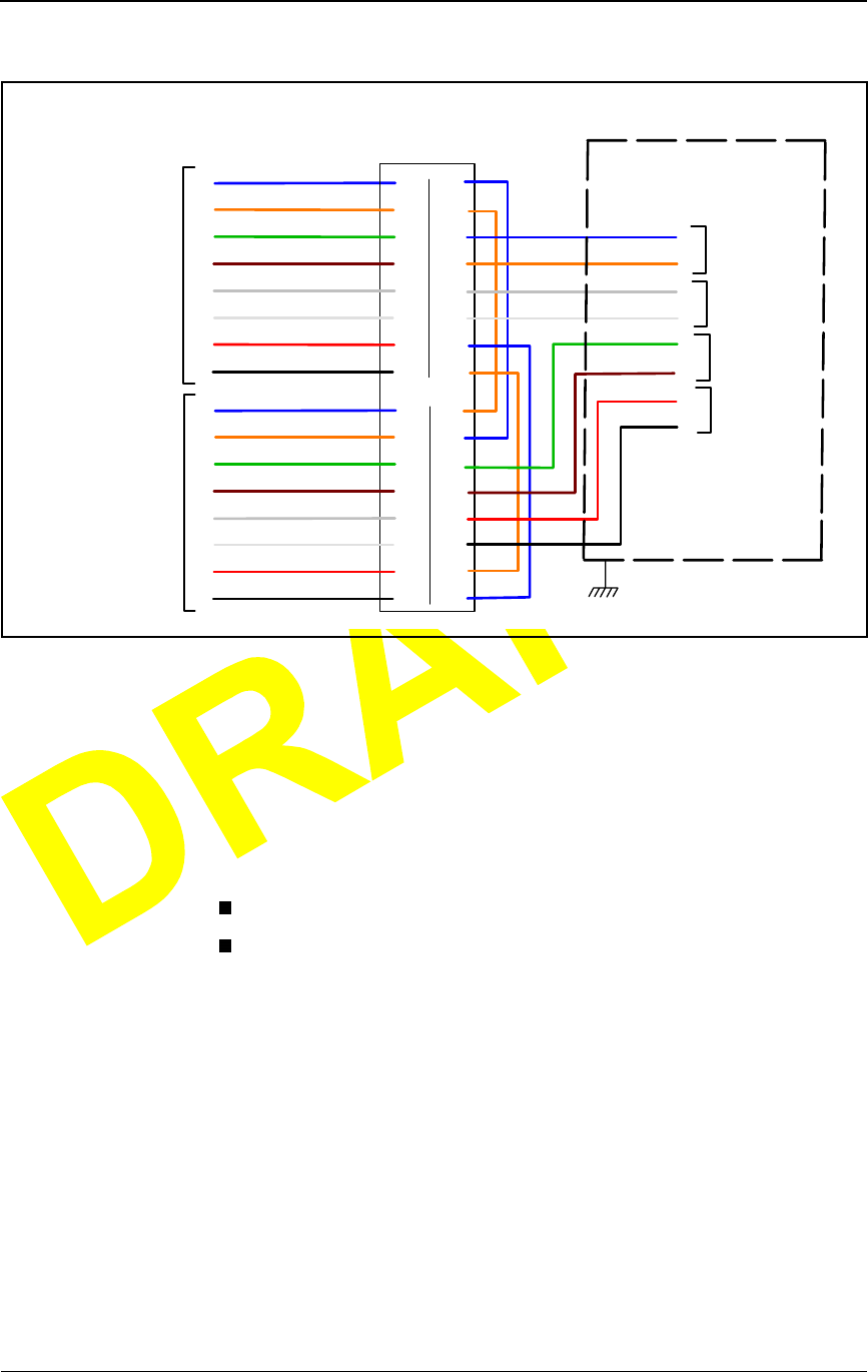
Figure 3-10. Typical Fast Ethernet Site Schematic
Fiber Optic Continuity Test
This test is to ensure that the signal loss in the fiber optic assemblies meet the
specifications and that cables have not been damaged during installation. The
fiber optic continuity test consists of:
Cleaning the fiber optic cable
Testing the fiber optic cable
Demarcation
Panel
IFU Alpha
Fiber
Cable
Blue (FA-1)
Orange (FA-2)
Green (FA-3)
1
2
3
4Brown (FA-4)
Slate (FA-5)
White (FA-6)
Red (FA-7)
5
6
7
8Black (FA-8)
1A
1B
2A
2B
3A
3B
4A
4B
Rear Front
1A
1B
2A
2B
3A
3B
4A
4B
IFU Beta
Fiber
Cable
1
2
3
4
5
6
7
8
5A
5B
6A
6B
7A
7B
8A
8B
5A
5B
6A
6B
7A
7B
8A
8B
1
3
2
4
IFU Alpha
Add/Drop
IFU Alpha
OAM&P
IFU Beta
Add/Drop
IFU Beta
OAM&P
Site Equipment
Cabinet
TX
RX
TX
RX
TX
RX
TX
RX
TX
RX
TX
RX
TX
RX
TX
RX Chassis to
Earth Ground
Blue (FB-1)
Orange (FB-2)
Green (FB-3)
Brown (FB-4)
Slate (FB-5)
White (FB-6)
Red (FB-7)
Black (FB-8)
Blue (FA-3)
Orange (FA-4)
Green (FB-3)
Brown (FB-4)
Slate (FA-5)
White (FA-6)
Red (FB-5)
Black (FB-6)

Installation Procedures
3-18 © 1999 Triton Network Systems, Inc. All Rights Reserved.
CONFIDENTIAL & PROPRIETARY
DO NOT COPY
To clean the fiber optic cable:
WA RN IN G : Never touch exposed fiber with any part of
your body. Fiber fragments can enter the skin and are
difficult to detect and remove.
AVERTISSEMENT : Ne jamais laisser une fibre nue
entrer en contact avec une partie quelconque du corps. Des
fragments de fibre peuvent entrer dans la peau, et sont
difficiles à déceler et à enlever.
DANGER: Invisible laser radiation. Avoid direct eye
exposure to the end of a fiber, fiber cord, or fiber pigtail.
The infrared light used in fiber optics systems is invisible,
but can cause serious injury to the eye.
AVERTISSEMENT : Rayonnement laser invisible.
Éviter l’exposition directe des yeux à l’extrémité d’une
fibre, d’un cordon à fibres ou d’une fibre amorce. La
lumière infrarouge utilisée dans les systèmes à fibres
optiques est invisible, mais peut provoquer des lésions
graves aux yeux.
CAUTION: Ensure the outside optical fiber connectors
are environmentally protected. Failure to do so may cause
contamination of the fiber surfaces.
MISE EN GARDE : S’assurer que les raccords extérieurs
fibre optique sont protégés contre l’environnement.
L’absence d’une telle protection peut entraîner la
contamination des surfaces des fibres.

Installing IFU Components
28 GHz Fast Ethernet IFU Installation (9/17/99) - R0.1 3-19
CONFIDENTIAL & PROPRIETARY
DO NOT COPY
1Remove the dust cap on the connector. Using the automatic cleaner, wipe
the connector once in each direction across cleaning pad.
2With canned air, blow a slow 3 to 4 second burst of air across fiber/ferrule
end face to dry connector then replace the dust cap.
3Repeat Step 1 and Step 2 on the other end of fiber optic cable.
NOTE: Never leave connectors unprotected after cleaning.
4Attach the fiber optic cable to the scope and inspect for dirt, grease,
defects, dust, oil, etc.
5Repeat Step 1 and Step 2, if necessary.
CAUTION: To reduce the risk of fiber optic cable
damage, use the following bend radius guidelines for
indoor/outdoor fiber optic cable:
Long-term (installed): bend radius is equal to 10 times
the diameter of the cable.
Short-term (during installation): bend radius is equal to
20 times the diameter of the cable.
MISE EN GARDE : Pour réduire le risque de dommage
aux câbles à fibres optiques, suivre les consignes suivantes
en matière de rayon de courbure des câbles à fibres
optiques extérieurs ou intérieurs :
Courbure à long terme (installée). Le rayon de courbure
ne doit pas dépasser 10 fois le diamètre du câble.
Courbure à court terme (pendant l’installation). Le
rayon de courbure ne doit pas dépasser 20 fois le
diamètre du câble.
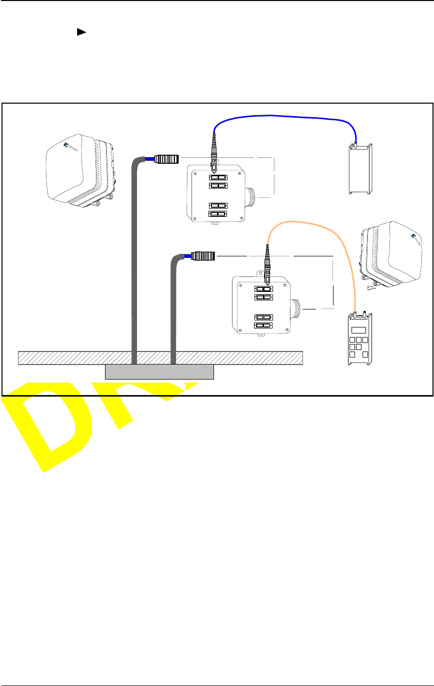
Installation Procedures
3-20 © 1999 Triton Network Systems, Inc. All Rights Reserved.
CONFIDENTIAL & PROPRIETARY
DO NOT COPY
To test the fiber optic cable:
1Connect fiber optic test adapters to the IFU Alpha and IFU Beta fiber
cables.
Figure 3-11. Fast Ethernet Fiber Optic Continuity Test Setup
2Carefully place the laser receiver IFU Beta test adapter (see Figure 3-11
and Table 3-7).
NOTE: Never connect the transmitter first.
3Connect the transmitter to the IFU Alpha test adapter as called out in
Table 3-7.
4Set the transmitter to 0 dBm continuous wave and 1310 nm.
5Turn on both units and take readings at the receiver. Record the results in
Table A-3 on page A-2.
NOTE: The received signal should be stronger than – 7.4 dBm (less
than 7.4 dB).
Outside Building
INSIDE BUILDING
Laser
Transmitter
Test
Adapter
IFU Beta
IFU Alpha
Demarcation Box
IFU Alpha
Fiber Cable
IFU Beta
Fiber Cable
1 Blue 2 Orange
3 Green 4 Brown
TEST BOX
5 Slate 6 White
7 Red 8 Black
Laser
Receiver
1 Blue 2 Orange
3 Green 4 Brown
TEST BOX
5 Slate 6 White
7 Red 8 Black
Test
Adapter

Installing an IFU
28 GHz Fast Ethernet IFU Installation (9/17/99) - R0.1 3-21
CONFIDENTIAL & PROPRIETARY
DO NOT COPY
Repeat steps 1 through 5 on each fiber optic cable.
Installing an IFU
IFUs are installed in the locations as specified by each site drawing. A
near-end IFU is the first installed IFU in a pair, and the far-end IFU is the
second in the pair. Figure 3-12 provides a close-up view of an installed IFU.
Installing an IFU is a two-part process:
1Mounting the IFU to the mounting bracket.
2Attaching cables to the IFU.
Table 3-7. Fast Ethernet Fiber Test Connections
IFU Beta
Fiber Name
IFU Beta Test
Adapter
Connector
IFU Alpha
Test Adapter
Connector
IFU Alpha
Fiber Name
Payload RX 2 Orange 1 Blue Payload TX
Payload TX 1 Blue 2 Orange Payload RX
Interconnect RX 8 Black 7 Red Interconnect TX
Interconnect TX 7 Red 8 Black Interconnect RX

Installation Procedures
3-22 © 1999 Triton Network Systems, Inc. All Rights Reserved.
CONFIDENTIAL & PROPRIETARY
DO NOT COPY
Mounting the IFU
Verify the correct IFU for location by checking the product number on the
IFU against the site drawing in the site engineering folder.
3Refer to Figure 3-12 and position the IFU (2) on the mounting studs (7)
and engage the top clamp.
4Install a snap ring (3) on each mounting stud (7).
CAUTION: Lifting hazard: Two people are required to
lift the Invisible Fiber™ unit. Grasp the Invisible Fiber™
unit underneath the lower edge and lift with both hands.
To prevent injury, keep your back straight and lift with
your legs, not your back. To prevent damage to the
Invisible Fiber™ unit and components, never attempt to
lift the radio by the attached cables.
MISE EN GARDE : Danger de levage. Il faut deux
personnes pour soulever l’unité Invisible FiberMD. Saisir
l’unité Invisible FiberMD au-dessous du rebord inférieur,
puis soulever l’unité avec les deux mains. Pour éviter les
lésions corporelles, garder le dos en position verticale et
soulever l’unité en utilisant les jambes et non pas les reins.
Pour éviter l’endommagement de l’unité Invisible FiberMD
et de ses composants, ne jamais essayer de soulever la
radio en tirant sur les câbles qui y sont attachés.
CAUTION: Keep tools and parts away from walkways.
When carrying large, heavy equipment (such as the
Invisible Fiber™ unit), obstacles (such as hand tools,
cables or components) may not be easily visible and can
cause accidents.
MISE EN GARDE : Garder les outils et les pièces loin
des allées. Lorsqu’on transporte des équipements lourds et
à grandes dimensions (tels que l’unité Invisible FiberMD),
les obstacles (tels que les outils à main, les câbles ou les
composants) sont parfois difficiles à voir et peuvent causer
des accidents.
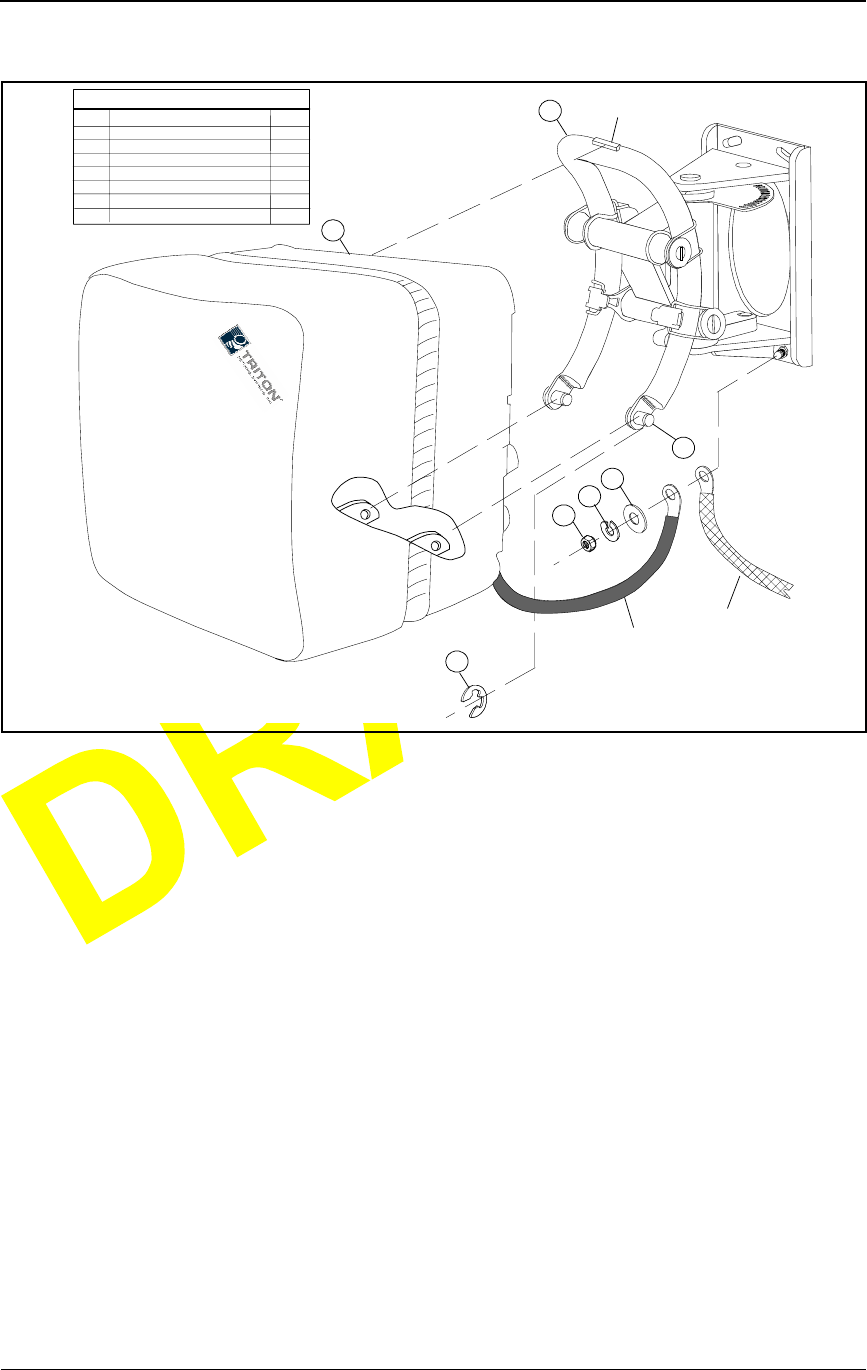
Installing an IFU
28 GHz Fast Ethernet IFU Installation (9/17/99) - R0.1 3-23
CONFIDENTIAL & PROPRIETARY
DO NOT COPY
Figure 3-12. Mounting the IFU
5Position the building ground strap, IFU ground strap, flat washer (4), and
lock washer (5) on the bottom bolt of the mounting bracket (1) and install
nut (6).
3
4
5
6
2
1
LEGEND
ITEM
1
2
3
4
5
6
7
DESCRIPTION
IFU M0UNTING BRACKET
IFU
SNAP RING
FLAT WASHER
LOCK WASHER
NUT
MOUNTING STUD
QTY
1
1
2
1
1
1
2
IFU
GROUND
STRAP
7
BUILDING
GROUND
STRAP
TOP
CLAMP

Installation Procedures
3-24 © 1999 Triton Network Systems, Inc. All Rights Reserved.
CONFIDENTIAL & PROPRIETARY
DO NOT COPY
Attaching IFU Cables
To test the fiber optic cable:
1Connect the power, alarm, and fiber optic cable to the IFU locations as
shown in Figure 3-13.
Figure 3-13. IFU Cable Connections
2Secure the power, alarm, and fiber optic cables to the building with
tie-wraps as needed.
DANGER – HIGH CURRENT HAZARD: Ensure that
the – 48 Vdc power source is set to the OFF position
before beginning the installation procedures for the
Invisible Fiber™ unit.
DANGER – L’HASARD DU COURANT ÉLEVÉ :
S’assurer que le bloc d’alimentation – 48 V CC est en
position HORS TENSION avant d’aborder les procédures
pour l’installation de l’unité Invisible FiberMD.

28 GHz Fast Ethernet IFU Installation (9/17/99) - R0.1 4-1
CONFIDENTIAL & PROPRIETARY
DO NOT COPY
4Commissioning
Procedures
This chapter provides the procedures for commissioning IFUs
The following topics are included in this chapter:
Aligning the Near-End IFU
Commissioning the Far-End IFU
Commissioning the Near-End IFU
Testing the Link
NOTE: Observe all federal and local laws, regulations,
electrical codes, building codes, fire codes, and licensing
agreements.
Il faut respecter l’ensemble des lois, règlements, codes d’électrique,
codes du bâtiment et codes des incendies du gouvernement fédéral
et des municipalités ainsi que tous les contrats de licence.
NOTE: Failure to follow the installation procedure described
in the Triton Network Systems’ product documentation may
result in damage to the Invisible Fiber™ unit and render the
unit unusable.
L’inobservation de la procédure d’installation décrite dans la
documentation du produit fournie par la société Triton Network
Systems peut endommager l’unité Invisible FiberMD et la rendre
inutilisable.

Commissioning Procedures
4-2 © 1999 Triton Network Systems, Inc. All Rights Reserved.
CONFIDENTIAL & PROPRIETARY
DO NOT COPY
Setup
Before Starting
Before starting the procedures in this chapter, ensure that the IFUs have been
mounted at the near-end site and far-end site, and that the cables have been
tested.
Preparing for Installation
Table 4-1 identifies the basic commissioning tools required for
commissioning the near-end and far-end sites.
Table 4-1. Site Commissioning Tools
Item
No. Description Qty.
1 IFU Link Manager test cable 2
2 IFU Link Manager software 2
3 Hub (10BaseT) 1
4 Laptop with IFU Link Manager and SmartApplication™
software installed 2
5SmartBits™ (SB-200) test set 2
6 100BaseT to 100BaseFX media converters 2
7 10BaseT cable (CAT-5) 4
8 SC-to-SC couplers 2
9 MT-RJ to SC fiber adapters (MT-RJ SC) 2
10 Digital multimeter (measures DC voltage up to 100V,
accuracy, 0.3% or better)
2
11 BNC/banana interface cable 1
12 Site engineering folder 1
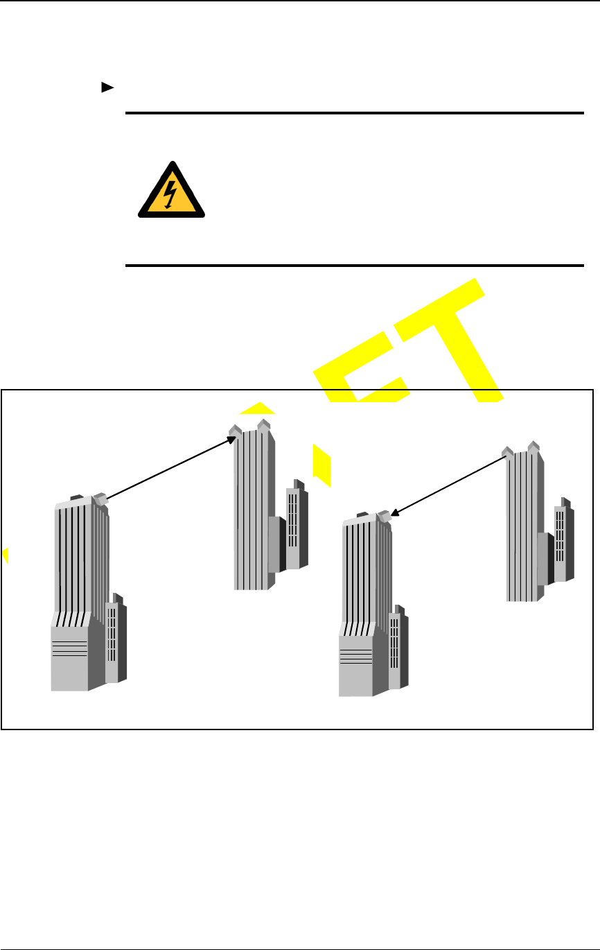
Aligning the IFU
28 GHz Fast Ethernet IFU Installation (9/17/99) - R0.1 4-3
CONFIDENTIAL & PROPRIETARY
DO NOT COPY
Aligning the IFU
To align the IFU:
1Loosen the four vertical alignment screws on the IFU mounting bracket.
2Coarse align the near-end IFU to the far-end IFU pair and the far-end IFU
to the near-end IFU using an optical alignment tool (see Figure 4-1).
Figure 4-1. Coarse Alignment
3Loosen the horizontal alignment nut on the holding bracket. Coarse align
the near-end IFU to the designated far-end IFU using an optical alignment
tool.
4Tighten the four vertical screws and single horizontal nut on the IFU
mounting bracket.
DANGER – HIGH VOLTAGE HAZARD: Do not work
on the system or connect or disconnect cables during
periods of lightning activity, rainy weather, or both.
DANGER – L’HASARD DU TENSION ÉLEVÉ : Ne
pas travailler sur le système ni brancher ni débrancher les
câbles durant l’activité de la foudre, par de temps
pluvieux, ou tous le deux.
COARSE ALIGN
NEAR-END IFU
NEAR-END
FAR-END
COARSE ALIGN
FAR-END IFU
NEAR-END
FAR-END
Commissioning Procedures
4-4 © 1999 Triton Network Systems, Inc. All Rights Reserved.
CONFIDENTIAL & PROPRIETARY
DO NOT COPY
5Set the – 48 Vdc power source to ON.
6Remove the protective cap from the IFU test connector.
7Connect the IFU test cable to the test port of the near-end IFU.
Figure 4-2. Alignment Test Setup
8Connect the BNC plug of the test cable to the BNC/banana interface
cable.
9Connect the banana plug of the BNC/banana interface cable to the
multimeter (red plug to the volt terminal, black plug to the Common
terminal).
DANGER – HIGH CURRENT HAZARD: Do not turn
on power before reading the Triton Network Systems’
product documentation. This device has a – 48 Vdc
(4 amps operating peak per feed) direct current input.
DANGER – L’HASARD DU COURANT ÉLEVÉ : Ne
pas mettre la tension avant de lire la documentation du
produit fournie par la société Triton Network Systems. Cet
appareil a une alimentation directe de – 48 V CC (courant
de pointe de 4 ampères par ligne d’alimentation).
IFU
LAPTOP WITH
IFU LINK MANAGER
TEXT
TEXT
TEXT TEXT
TEXT TEXT
TEXT TE XT
TEXT TE XT
TEXT
TE XT
3
+-
TEST CABLE BNC/BANANA
MULTIMETER

Aligning the IFU
28 GHz Fast Ethernet IFU Installation (9/17/99) - R0.1 4-5
CONFIDENTIAL & PROPRIETARY
DO NOT COPY
10 Turn on the multimeter and set it up to measure DC voltage.
11 Connect the RJ-45 plug of the test cable to the laptop.
12 Power up the laptop and access the IFU Link Manager application.
Initialize the IFU if it has not been initialized (refer to IFU Link Manager
online help).
13 Log on to the near-end IFU.
14 Use the IFU Link Manager application to set the near-end IFU radio
transmitter to ON (see IFU Link Manager online help).
15 Ensure that the power control is OFF.
Repeat this procedure for the far-end IFU.
WA RN IN G : Beware! Radio transmitter is ON when the
red light indicator on back side of Invisible Fiber™ unit is
illuminated. Observe all radio frequency energy exposure
and service interruption cautions.
MISE EN GARDE : Attention ! Le poste émetteur est EN
MARCHE lorsque le témoin rouge sur le dos de l’unité
Invisible FiberMD est allumé. Respecter toutes les mises en
garde concernant l’exposition aux radiofréquences et
l’interruption de service.
WA RN IN G – RF EXPOSURE HAZARD: Ensure the
safety of all personnel. Do not stand in front of the
Invisible Fiber™ unit (antenna) in order to avoid possible
harmful radio frequency energy exposure. Serious bodily
injury may result.
MISE EN GARDE – RF EXPOSURE HAZARD :
Assurer la sécurité de tout le personnel. Ne pas rester
debout devant l’unité Invisible FiberMD (l’antenne) afin
d’éviter toute exposition dangereuse aux radiofréquences.
Les lésions corporelles serieux s’ensuivre.

Commissioning Procedures
4-6 © 1999 Triton Network Systems, Inc. All Rights Reserved.
CONFIDENTIAL & PROPRIETARY
DO NOT COPY
Commissioning the IFU
To commission the far-end IFU:
1Ensure the near-end IFU transmitter is set to ON.
2Loosen the four vertical screws on the holding bracket.
3While viewing the multimeter, sweep the IFU vertically by pointing the
IFU all the way up and then down. The measured voltage of the
multimeter displays a succession of peak signals as the IFU moves.
Specifically, the signal displays a “small” peak, a relatively higher peak,
and then the “small” peak. Note the approximate position of the IFU
when the higher peak occurs and the corresponding voltage value. The
peak voltage should be approximately 3 Vdc.
4Move the IFU to the higher peak position as indicated by the multimeter
display.
5Tighten the four vertical screws on the IFU mounting bracket.
6Loosen the horizontal alignment nut on the IFU mounting bracket.
WA RN IN G : Beware! Radio transmitter is ON when the
red light indicator on back side of Invisible Fiber™ unit is
illuminated. Observe all radio frequency energy exposure
and service interruption cautions.
MISE EN GARDE : Attention ! Le poste émetteur est EN
MARCHE lorsque le témoin rouge sur le dos de l’unité
Invisible FiberMD est allumé. Respecter toutes les mises en
garde concernant l’exposition aux radiofréquences et
l’interruption de service.
WA RN IN G – RF EXPOSURE HAZARD: Ensure the
safety of all personnel. Do not stand in front of the
Invisible Fiber™ unit (antenna) in order to avoid possible
harmful radio frequency energy exposure. Serious bodily
injury may result.
MISE EN GARDE – RF EXPOSURE HAZARD :
Assurer la sécurité de tout le personnel. Ne pas rester
debout devant l’unité Invisible FiberMD (l’antenne) afin
d’éviter toute exposition dangereuse aux radiofréquences.
Les lésions corporelles serieux s’ensuivre.

Commissioning the IFU
28 GHz Fast Ethernet IFU Installation (9/17/99) - R0.1 4-7
CONFIDENTIAL & PROPRIETARY
DO NOT COPY
7Sweep the IFU from the far left to the far right. The measured voltage of
the multimeter displays a succession of peak signals as the IFU moves.
Note the approximate position of the IFU when the higher peak occurs
and the corresponding voltage value.
8Move the IFU to the higher peak position as indicated by the multimeter
display.
9Tighten the horizontal alignment nut on the IFU mounting bracket.
To commission the far-end IFU:
1Ensure the far-end IFU transmitter is set to ON.
2Loosen the four vertical screws on the IFU mounting bracket.
3While viewing the multimeter, sweep the IFU vertically by pointing the
IFU all the way up and then down. The measured voltage of the
multimeter displays a succession of peak signals as the IFU moves.
Specifically, the signal displays a “small” peak, a relatively higher peak,
and then the “small” peak. Note the approximate position of the IFU
when the higher peak occurs and the corresponding voltage value. The
peak voltage should be approximately 3 Vdc.
WA RN IN G : Beware! Radio transmitter is ON when the
red light indicator on back side of Invisible Fiber™ unit is
illuminated. Observe all radio frequency energy exposure
and service interruption cautions.
MISE EN GARDE : Attention ! Le poste émetteur est EN
MARCHE lorsque le témoin rouge sur le dos de l’unité
Invisible FiberMD est allumé. Respecter toutes les mises en
garde concernant l’exposition aux radiofréquences et
l’interruption de service.
WA RN IN G – RF EXPOSURE HAZARD: Ensure the
safety of all personnel. Do not stand in front of the
Invisible Fiber™ unit (antenna) in order to avoid possible
harmful radio frequency energy exposure. Serious bodily
injury may result.
MISE EN GARDE – RF EXPOSURE HAZARD :
Assurer la sécurité de tout le personnel. Ne pas rester
debout devant l’unité Invisible FiberMD (l’antenne) afin
d’éviter toute exposition dangereuse aux radiofréquences.
Les lésions corporelles serieux s’ensuivre.

Commissioning Procedures
4-8 © 1999 Triton Network Systems, Inc. All Rights Reserved.
CONFIDENTIAL & PROPRIETARY
DO NOT COPY
4Move the IFU to the higher peak position as indicated by the multimeter
display.
5Tighten the four vertical screws on the IFU mounting bracket.
6Loosen the horizontal alignment nut on the IFU mounting bracket.
7Sweep the IFU from the far left to the far right. The measured voltage of
the multimeter displays a succession of peak signals as the IFU moves.
Note the approximate position of the IFU when the higher peak occurs
and the corresponding voltage value.
8Move the IFU to the higher peak position as indicated by the multimeter
display.
9Tighten the horizontal alignment nut on the IFU mounting bracket.
10 Access the IFU Link Manager application and enable Power Control for
both the near-end and the far-end IFUs (see IFU Link Manager online
help).
11 Record the minimum, maximum, and actual RSSI levels set for the IFU in
Table A-4 and Table A-6.
12 Turn off the laptops, disconnect the test cables, and replace the protective
caps on the IFU test connectors.
13 Secure all IFU cabling with UV-rated tie-wraps. Continue to tie wrap the
cables every 18 inches until they enter the building.
Fast Ethernet Payload Test
28 GHz Fast Ethernet IFU Installation (9/17/99) - R0.1 4-9
CONFIDENTIAL & PROPRIETARY
DO NOT COPY
Fast Ethernet Payload Test
This test ensures that IFUs function correctly and pass the customer payload
traffic error-free before the IFUs are added to the network.
To perform the payload test:
1Connect the SmartBits™ test set from the 100BaseFX port 3 to the IFU
Alpha 100BaseFX Add/Drop port on the patch panel with the MT-RJ to
SC fiber adapters (see Figure 4-3).
2Power up the Laptop and connect the Ethernet port to the SmartBits™ test
set with a CAT-5 cable.
Figure 4-3. Fast Ethernet Payload Test Setup
IFU ALPHA IFU BETA
LAPTOP
With SmartBits
OUTSIDE BUILDING
INSIDE BUILDING
PATCH PANEL
IFU IFU
Add-Drop
SmartBits TEST SET
Port 3
Add-Drop
Port 4
DEMARCATION BOX
Add-Drop Add-Drop
Payload
Add-Drop
100BaseFX
SC to SC
MT-RJ to SC
ADAPTER
SC to SC
COUPLER
100BaseFX
SC to SC
MT-RJ to SC
ADAPTER
SC to SC
COUPLER
TM
TM

Commissioning Procedures
4-10 © 1999 Triton Network Systems, Inc. All Rights Reserved.
CONFIDENTIAL & PROPRIETARY
DO NOT COPY
3Connect the SmartBits™ test set from 100BaseFX port 4 to IFU Beta
100BaseFX Payload port on the patch panel with the MT-RJ to SC fiber
adapters.
4Turn on power to the SmartBits™ test set.
5On the laptop, open the SmartApplication™ program.
6Select File>Open and then click Building Payload Test (file provided by
Triton Network Systems).
7Select Run then click Packet Loss to run the Packet Loss tests.
8Record the results of 64, 76, 128, 164, 512, 1024, and 1518 byte packet
tests in Fast Ethernet Payload Test on page A-4.
9Stop all tests, disconnect the test equipment, and return the equipment to
its previous state.
Repeat this procedure for each IFU site.
Fast Ethernet Link Performance Test
28 GHz Fast Ethernet IFU Installation (9/17/99) - R0.1 4-11
CONFIDENTIAL & PROPRIETARY
DO NOT COPY
Fast Ethernet Link Performance Test
This test ensures that the installed IFUs are functional and pass payload traffic
error-free, before the IFUs are added to the network. The Fast Ethernet test set
sends data packets to the near-end IFU. The near-end IFU transmits the data
packets to the far-end IFU, to the Fast Ethernet test set, and back.
To perform the link performance test:
1Ensure that both the near-end and the far-end IFUs have been aligned.
2At the near-end site power up the laptop and connect the Ethernet port to
the hub via CAT-5 cable (see Figure 4-4).
Figure 4-4. Fast Ethernet Link Test Setup
FAR-END IFU
NEAR-END IFU
PATCH PANEL
LAPTOP With
SmartApplications
OUTSIDE BUILDING
INSIDE BUILDING
MEDIA
CONVERTER
OUTSIDE BUILDING
INSIDE BUILDING
IFU IFU
HUB
OAM&P
10BaseFL
100BaseFX
SC to SC
SmartBits Test Set
CAT-5
CAT-5
Port 3 Ethernet
Port
MEDIA
CONVERTER
10BaseFL
CAT-5
MT-RJ to SC
ADAPTER
Add-Drop
PATCH PANEL
IFU IFU
OAM&P
Add-Drop
CAT-5
SmartBits Test Set
Port 4 Ethernet
Port
SC to SC
COUPLER
100BaseFX
SC to SC
MT-RJ to SC
ADAPTER
SC to SC
COUPLER
TM
TM TM

Commissioning Procedures
4-12 © 1999 Triton Network Systems, Inc. All Rights Reserved.
CONFIDENTIAL & PROPRIETARY
DO NOT COPY
3Connect a power cable to the hub.
NOTE: When connecting the laptop, hub, and converters, make sure
the link light is illuminated on all of the devices. If the light does not
illuminate when both ends of the cable are connected, check the
connections.
4Connect the media converter to the hub with a CAT-5 cable.
5In the site equipment cabinet, connect a 10BaseFL cable between the hub
and the OAM&P port for the near-end IFU being tested.
6Connect a power cable to the media converter and the SmartBits™ test set
and power up the SmartBits™ test set.
7Connect the Ethernet port on the back of the SmartBits™ test set to the
hub input with a CAT-5 cable.
8Connect the SmartBits™ test set Port 3 to the near-end IFU’s Add/Drop
port in the site equipment cabinet. Connect the MT-RJ to SC adapters and
the 100BaseFX fiber with the coupler from Port 3 to the IFU’s Add/Drop
port on the site equipment cabinet.
9At the far-end site, connect a power cable to the media converter and the
SmartBits™ test set and power up the SmartBits™ test set.
10 Connect the SmartBits™ test set Port 4 to the far-end IFU Add/Drop port
in the site equipment cabinet. Connect the MT-RJ to SC adapters and the
100BaseFX fiber with the coupler from port 4 to the IFU's Add/Drop port
on the site equipment cabinet.
11 Connect the media converter to the SmartBits™ with a CAT-5 cable.
12 Connect the far-end IFU’s OAM&P port in the site equipment cabinet to
the converter with a 10BaseFL cable.
13 On the near-end laptop, select Start>Run and then type command to
open a DOS box window.
14 Type Ping XXX.XXX.XXX.XXX (XXX is the IP address of the
SmartBits™ test set) to link the SmartBits™ test sets.
15 On the laptop, open the SmartApplication™ program.
16 Select File>Open and then click IFU Link Test (file provided by Triton
Network Systems).
17 Select Run and then click Packet Errors to run the Packet Error tests.

Fast Ethernet Link Performance Test
28 GHz Fast Ethernet IFU Installation (9/17/99) - R0.1 4-13
CONFIDENTIAL & PROPRIETARY
DO NOT COPY
18 Record the results of 64, 76, 128, 164, 512, 1024, and 1518 byte packet
tests in Fast Ethernet Link Performance Test on page A-4.
19 Stop all tests, disconnect the test equipment, and return the equipment to
its previous state.
Repeat this procedure for each radio link in the network.

Commissioning Procedures
4-14 © 1999 Triton Network Systems, Inc. All Rights Reserved.
CONFIDENTIAL & PROPRIETARY
DO NOT COPY

28 GHz Fast Ethernet IFU Installation (9/17/99) - R0.1 5-1
CONFIDENTIAL & PROPRIETARY
DO NOT COPY
5Removing an IFU
This chapter provides the procedures for removing an IFU.
The following topics are included in this chapter:
Servicing an IFU
Removing an IFU
NOTE: Observe all federal and local laws, regulations,
electrical codes, building codes, fire codes, and licensing
agreements.
Il faut respecter l’ensemble des lois, règlements, codes d’électrique,
codes du bâtiment et codes des incendies du gouvernement fédéral
et des municipalités ainsi que tous les contrats de licence.
NOTE: Failure to follow the installation procedure described
in the Triton Network Systems’ product documentation may
result in damage to the Invisible Fiber™ unit and render the
unit unusable. Read through the entire installation procedure
before beginning installation.
L’inobservation de la procédure d’installation décrite dans la
documentation du produit fournie par la société Triton Network
Systems peut endommager l’unité Invisible FiberMD et la rendre
inutilisable.
CAUTION: The Invisible Fiber™ unit contains no owner
or user serviceable parts. Opening the radio unit or
tampering with any of its seals voids all warranties.
MISE EN GARDE : L’unité Invisible Fibermd contient
pas de parts utilés par le propriétaire ou l’usager.
Ouverture de l’unité de la radio ou toucher aux scelles rend
toute garantie nulle et non avenue.

Removing an IFU
5-2 © 1999 Triton Network Systems, Inc. All Rights Reserved.
CONFIDENTIAL & PROPRIETARY
DO NOT COPY
Servicing an IFU
Servicing an IFU is done at the factory. To service the IFU, remove it and
replace it with a new IFU. Send the IFU needing service to the factory.
Removing an IFU
Removing an IFU is a two-part process:
1Removing the power and cables from the IFU.
2Removing the IFU from the mounting bracket.
Removing Cables
To remove power and cables from the IFU:
CAUTION: Ensure that the – 48 Vdc power source is set
to the OFF position before attaching power cables to the
Invisible Fiber™ Unit.
MISE EN GARDE : S’assurer que le bloc d’alimentation
– 48 V CC est en position HORS TENSION avant
d’attacher les câbles d’alimentation à l’unité Invisible
Fibermd.
WA RN IN G : Never touch exposed fiber with any part of
your body. Fiber fragments can enter the skin and are
difficult to detect and remove.
AVERTISSEMENT : Ne jamais laisser une fibre nue
entrer en contact avec une partie quelconque du corps. Des
fragments de fibre peuvent entrer dans la peau, et sont
difficiles à déceler et à enlever.
Removing an IFU
28 GHz Fast Ethernet IFU Installation (9/17/99) - R0.1 5-3
CONFIDENTIAL & PROPRIETARY
DO NOT COPY
1Set the – 48 Vdc power source to the OFF position.
2Remove the power and fiber optic cables from the IFU locations as shown
in Figure 5-1.
Figure 5-1. IFU Cable Connections
CAUTION: Ensure the outside optical fiber connectors
are environmentally protected. Failure to do so may cause
contamination of the fiber surfaces.
MISE EN GARDE : S’assurer que les raccords extérieurs
fibre optique sont protégés contre l’environnement.
L’absence d’une telle protection peut entraîner la
contamination des surfaces des fibres.

Removing an IFU
5-4 © 1999 Triton Network Systems, Inc. All Rights Reserved.
CONFIDENTIAL & PROPRIETARY
DO NOT COPY
Removing an IFU from a Mounting Bracket
To remove an IFU from its mounting bracket:
1Remove the nut (6), lock washer (5), flat washer (4), and earth ground
strap from the bottom bolt of the mounting bracket (1) (see Figure 5-2).
2Remove two snap rings (3) from mounting studs (7) as shown in
Figure 5-2.
3Disengage the top IFU clamp and remove the IFU (2) from the mounting
bracket (1) as shown in Figure 5-2.
4Replace dust caps on exposed IFU and cable connectors.
CAUTION: Lifting hazard: Two people are required to
lift the Invisible Fiber™ unit. Grasp the Invisible Fiber™
unit underneath the lower edge and lift with both hands. To
prevent injury, keep your back straight and lift with your
legs, not your back. To prevent damage to the Invisible
Fiber™ unit and components, never attempt to lift the
radio by the attached cables.
MISE EN GARDE : Danger de levage. Il faut deux
personnes pour soulever l’unité Invisible FiberMD. Saisir
l’unité Invisible FiberMD au-dessous du rebord inférieur,
puis soulever l’unité avec les deux mains. Pour éviter les
lésions corporelles, garder le dos en position verticale et
soulever l’unité en utilisant les jambes et non pas les reins.
Pour éviter l’endommagement de l’unité Invisible FiberMD
et de ses composants, ne jamais essayer de soulever la
radio en tirant sur les câbles qui y sont attachés.
CAUTION: Keep tools and parts away from walkways.
When carrying large, heavy equipment (such as the
Invisible Fiber™ Unit), obstacles (such as hand tools,
cables or components) may not be easily visible and can
cause accidents.
MISE EN GARDE : Garder les outils et les pièces loin
des allées. Lorsqu’on transporte des équipements lourds et
à grandes dimensions (tels que l’unité Invisible FiberMD),
les obstacles (tels que les outils à main, les câbles ou les
composants) sont parfois difficiles à voir et peuvent causer
des accidents.
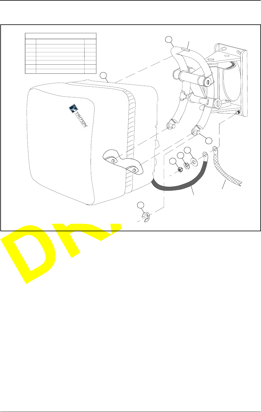
Packing the IFU for Shipment
28 GHz Fast Ethernet IFU Installation (9/17/99) - R0.1 5-5
CONFIDENTIAL & PROPRIETARY
DO NOT COPY
Figure 5-2. IFU Removal
5To install a new IFU, see Mounting the IFU on page 3-22 and Attaching
IFU Cables on page 3-24.
Packing the IFU for Shipment
Use the original packing material to ship the IFU to the factory. Should the
packing material not be available, contact Triton Network Systems (see
Contacting Triton Network Systems, Inc. on page xi) for packing instructions.
3
4
5
6
2
1
LEGEND
ITEM
1
2
3
4
5
6
7
DESCRIPTION
IFU M0UNTING BRACKET
IFU
SNAP RING
FLAT WASHER
LOCK WASHER
NUT
MOUNTING STUD
QTY
1
1
2
1
1
1
2
IFU
GROUND
STRAP
7
BUILDING
GROUND
STRAP
TOP
CLAMP

Removing an IFU
5-6 © 1999 Triton Network Systems, Inc. All Rights Reserved.
CONFIDENTIAL & PROPRIETARY
DO NOT COPY

28 GHz Fast Ethernet IFU Installation (9/17/99) - R0.1 A-1
CONFIDENTIAL & PROPRIETARY
DO NOT COPY
AIFU Test Results
This appendix contains tables for recording the power, alarm, fiber optic, and
commissioning test data.
Power Source Tests
Table A-1. Power Supply Test Results
Pins Results Pass Criteria Pass/Fail
IFU Alpha - A & C – 46 Vdc to – 56 Vdc
IFU Alpha - B & H – 46 Vdc to – 56 Vdc
IFU Beta - A & C – 46 Vdc to – 56 Vdc
IFU Beta - B & H – 46 Vdc to – 56 Vdc
IFU Gamma - A & C – 46 Vdc to – 56 Vdc
IFU Gamma - B & H – 46 Vdc to – 56 Vdc

IFU Test Results
A-2 © 1999 Triton Network Systems, Inc. All Rights Reserved.
CONFIDENTIAL & PROPRIETARY
DO NOT COPY
Alarm Cable Verification
Fast Ethernet Fiber Optic Test
Table A-2. Alarm Cable Wiring Verification
Alarm
Suppressor
IFU Alpha Wire Color Verify Alarm
Suppressor
IFU Beta Wire Color Verify
1 (in) White/Black 1 (in) White/Black
2 (in) White/Brown 2 (in) White/Brown
3 (in) White/Red 3 (in) White/Red
4 (in) White/Orange 4 (in) White/Orange
Shield Shield
Table A-3. Fast Ethernet Fiber Optic Test Results
IFU Alpha Test Adapter
End Fiber Signal Strength
>– 7.4 dBm @ 1310 nm IFU Beta Test Adapter
End
IFU Alpha Payload TX IFU Beta Payload RX
IFU Alpha Payload RX IFU Beta Payload TX
IFU Alpha Interconnect TX IFU Beta Interconnect RX
IFU Alpha Interconnect RX IFU Beta Interconnect TX
Far-End Test
28 GHz Fast Ethernet IFU Installation (9/17/99) - R0.1 A-3
CONFIDENTIAL & PROPRIETARY
DO NOT COPY
Far-End Test
Near-End Test
Table A-4. Far-End Test Results #1
IFU Number Min/Max
Signal
Strength
IFU Signal
Strength Set Pass/Fail
Table A-5. Far-End Test Results #2
IFU Number Min/Max
Signal
Strength
IFU Signal
Strength Set Pass/Fail
Table A-6. Near-End Test Results #1
IFU Number Min/Max
Signal
Strength
IFU Signal
Strength Set Pass/Fail
Table A-7. Near-End Test Results #2
IFU Number Min/Max
Signal
Strength
IFU Signal
Strength Set Pass/Fail

IFU Test Results
A-4 © 1999 Triton Network Systems, Inc. All Rights Reserved.
CONFIDENTIAL & PROPRIETARY
DO NOT COPY
Fast Ethernet Payload Test
Fast Ethernet Link Performance Test
Table A-8. Payload Test
Packet Size
(Bytes) Total Packets
Sent (Port 3) Total Packets
Received (Port 4) Port-Pair Packet
Loss (% of Total) Total Dropped
Packets (Bytes)
64
76
128
164
512
1024
1518
Table A-9. Link Performance Test
Packet Size
(Bytes) Total Packets
Sent (Port 3) Total Packets
Received (Port 4) Port-Pair Packet
Loss (% of Total) Total Dropped
Packets (Bytes)
64
76
128
164
512
1024
1518

Product Glossary - R0.1 glossary-5
CONFIDENTIAL & PROPRIETARY
DO NOT COPY
Invisible Fiber™ Product
Glossary
10BaseFL
Part of the IEEE 802.1j standard for 10 Mbps Ethernet fiber.
10BaseT
IEEE 802.3 standard specifying Ethernet over unshielded twisted pair cables.
99.999% availability
(Also known as five 9s availability.) Amount of time the system is expected to
be available. If the system is available 99.999% of the time, expected down
time is approximately six minutes per year, derived as follows:
Days per year X hours per day X (100–99.999) ÷ 100 X 60 =
365.25 X 24 X (100–99.999) ÷ 100 X 60 = 5.2 minutes
100BaseFX
Part of the IEEE 802.3u standard for 100 Mbps Ethernet over fiber.
A
Add/Drop Multiplexer (ADM)
A device that provides an interface between the different signals in a digital
T-carrier or SONET network. When an ADM is inserted in a transmission
line, it enables lower rate signals to be extracted (dropped) and transported
differently (electrical or optical). Similarly, a lower rate signal can be inserted
(added) into a higher rate signal.
ADD/DROP
MULTIPLEXER
Signals added and dropped
at an intermediate point in
the transmission (via a
multiplexer)
Communication Flow

glossary-6 © 1999 Triton Network Systems, Inc. All Rights Reserved.
CONFIDENTIAL & PROPRIETARY
DO NOT COPY
ADM
See Add/Drop Multiplexer (ADM).
AIS
See Alarm Indication Signal (AIS).
Alarm Indication Signal (AIS)
A special signal that is transmitted to downstream equipment for specific
equipment fault conditions.
antenna
A mechanical device that can convert electrical signals to and from
electromagnetic waves. An IFU contains an antenna.
Asynchronous Transfer Mode (ATM)
A cell-based protocol, developed by the ITU-T, for transmitting and switching
voice, video, and data traffic. ATM technology does not use a fixed timing
reference, hence the name asynchronous.
ATM
See Asynchronous Transfer Mode (ATM).
atmospheric absorption
Amount of energy lost when radio waves are transmitted due to the presence
of atmospheric gases.
attenuation
The reduction in the strength of a signal measured in dB. See also
propagation loss.
azimuth
The horizontal angle the radiating lobe of an antenna makes. When you adjust
an IFU by its azimuth, you move it on its horizontal plane (left to right or right
to left).
B
backbone
A backbone is the transport path that provides connectivity to other paths. On
the Internet or a WAN, the backbone is a series of paths to which local,
regional, or global networks connect.

Product Glossary - R0.1 glossary-7
CONFIDENTIAL & PROPRIETARY
DO NOT COPY
backhaul
A transmission path used to move traffic to/from a remote location from/to a
central location. The message can be routed “out of its way” so that it arrives
at its destination more quickly. A network can perform a back haul
transmission if a direct communication link is busy and an indirect link would
be faster. (The verb form is back haul.)
bandwidth
The range of frequencies over which a signal is transmitted.
BER
See Bit Error Rate (BER).
Bit Error Rate (BER)
The number of bit errors detected – displayed as the ratio of the average
number of errored bits in a given number of bits sent. The BER is used to
measure transmission quality. For example, a BER of 10–12 is equivalent to
one error in a trillion bits, which means that for:
SONET OC-3, one error bit is detected approximately every 1.8
hours
Fast Ethernet, one error bit is detected approximately every 2.8 hours.
BNC connector
Bayonet Neil-Concelman connector. A bayonet type of connector for coaxial
cables in an Ethernet network.
C
Central Office (CO)
Location at which one or more switches reside for aggregating voice or data
traffic.
Central Processing Unit (CPU)
Central controller that coordinates functions in the IFU.
channel
Physical medium through which signals are transmitted. In optical fiber
transmissions, a channel is a separate wavelength of light within a combined
multiplexed light stream.
channelization
Logically subdividing a frequency (normally assigned by a regulatory agency
for the delivery of broadband wireless services).

glossary-8 © 1999 Triton Network Systems, Inc. All Rights Reserved.
CONFIDENTIAL & PROPRIETARY
DO NOT COPY
CLEC
Independent company that competes with the already established local
telephone company by providing its own network and switching. CLEC
distinguishes a new or potential competitor from an established local
exchange carrier (LEC). The term originated from the Telecommunications
Act of 1996, which was intended to promote competition among
long-distance and local phone service providers.
CO
See Central Office (CO).
cochannel interference
Interference between signals transmitted within one radio frequency channel.
colocation
Space set aside for a customer’s telecommunications equipment on the service
provider’s premises. For example, a web site owner could place its computer
server on the premises of an ISP, or an ISP could locate its network router at a
company that supplies switching services to other ISPs.
Competitive Local Exchange Carrier
See CLEC.
commissioning
Tasks required to enable equipment to be placed in a live network. IFU
commissioning tasks include configuration and antenna alignment.
configuration management
The process of setting equipment attributes that enables equipment to function
as intended.
consecutive point
Network architecture implemented via a point-to-point-to-point design.
CPE
See Customer Premise Equipment (CPE).
CPU
See Central Processing Unit (CPU).
Customer Premise Equipment (CPE)
Equipment (such as telephones and computers) installed at a customer’s
office.
customer site
Network equipment configuration for a location at which network access is
provided in a carrier’s consecutive point network.

Product Glossary - R0.1 glossary-9
CONFIDENTIAL & PROPRIETARY
DO NOT COPY
Crane rain model
System of formulas, charts, and maps developed by Robert K. Crane to depict
a global prediction of attenuation caused by rain. See also rain attenuation.
D
dB
Decibel. The unit of measurement for signal strength, usually the ratio
between a transmitted signal and a standard signal source.
decibel (dB)
See dB.
demarcation point
Logical dividing point between equipment and a network.
E
Element Management System (EMS)
Software application used to manage network equipment.
EMS
See Element Management System (EMS).
Ethernet
Generic term for the IEEE 802.3 standard network transmission protocol.
exciter
An oscillator that enables a tuner to change its frequency.
F
fade margin
Amount of signal reduction a receiver can tolerate and continue to maintain
satisfactory performance.
far-end IFU
a) IFU at the other end of the link in the network (during site evaluation).
b) Second IFU installed in a linked pair of IFUs.
See also near-end IFU.
Fast Ethernet
Generic term for a IEEE standard network 100 Mbps transmission protocol.
fault management
Software that reports and identifies the source of network faults.
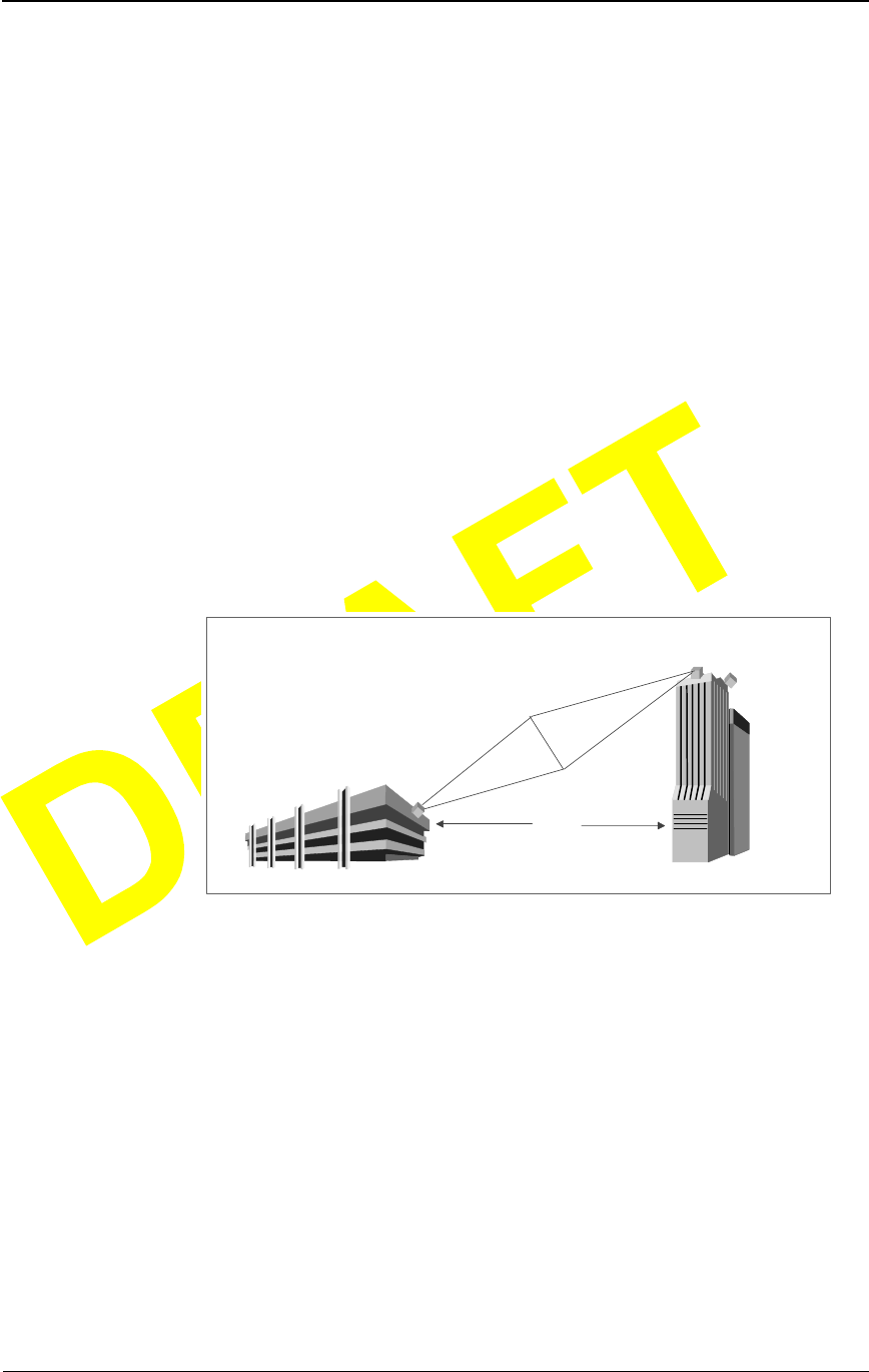
glossary-10 © 1999 Triton Network Systems, Inc. All Rights Reserved.
CONFIDENTIAL & PROPRIETARY
DO NOT COPY
fiber optics
Technology in which information is transmitted as light impulses from one
point to another through extremely thin glass or plastic wire or fiber.
fixed wireless system
Communication system that uses radio spectrum to provide services to
locations that are not mobile.
forward error correction
A system in which redundant information is generated at the transmitted end
so that the receiving unit can detect, locate, and correct any errors before
delivering the transmission.
free space propagation loss
Normal signal attenuation of radio waves transmitted through free space. Free
space loss increases logarithmically with increased hop distance.
Fresnel zone
A defraction zone around the line-of-sight path between two points as shown
in the following illustration.
The line-of-sight, including the Fresnel zone, must be clear of obstructions to
ensure communication between the IFUs.
G
gateway
A network point that aggregates traffic and acts as an entrance to another
network.
gateway site
Network equipment configuration for a location that aggregates customer
traffic in a consecutive point network for access to and from the Internet.
general purpose input/output
See GPIO.
2 Miles
Fresnel Zone

Product Glossary - R0.1 glossary-11
CONFIDENTIAL & PROPRIETARY
DO NOT COPY
GPIO
General Purpose Input/Output. Input/output ports on the IFU that provide
external control of equipment or detection and generation of external alarms.
Each IFU contains four GPIO ports (two input-only and two output-only).
H
histogram
A graphical representation of the distribution of a performance parameter. For
example, a histogram can show the value and proportion of time a particular
transmit power is used on a link.
hop distance
The distance between two communicating IFUs. One objective in network
design is to design link hop distances so that the RF path loss does not exceed
the path loss allowance for the required availability or grade of service.
HP OpenView™
Hewlett Packard’s network management product consisting of a suite of
software tools that enable network operations staff to manage the elements in
a network. HP OpenView Network Node Manager™ and the IFU Link
Manager software provide complete element management functions for an
IFU network.
hub
A location in a network where data is aggregated and forwarded to its
destination. A hub contains a switch and a router.
I
IFU
Invisible Fiber™ unit. Outdoor fixed-wireless device, designed to fiber-optic
specifications, that combines antenna, transceiver, modem, and controller
modules to transport high-bandwidth network-grade broadband telephony and
data services.
IFU Link Manager
Triton Network Systems’ software application that provides fault,
performance, configuration, and security management functions, enabling
onsite technicians and network management staff to configure and monitor
IFUs.
ILEC
Incumbent Local Exchange Carrier. Generic term for the carrier that
telephone company in the U.S. that was providing local service when the
Telecommunications Act of 1996 was enacted.

glossary-12 © 1999 Triton Network Systems, Inc. All Rights Reserved.
CONFIDENTIAL & PROPRIETARY
DO NOT COPY
In Service (IS)
System status indicating that an IFU is working with no known problems.
Incumbent Local Exchange Carrier
See ILEC.
indoor repeater site
Location used to extend a consecutive point network to enable future
customer access.
Internet Protocol
See IP.
Internet Service Provider (ISP)
An operator that provides its customers access to the Internet.
Invisible Fiber™ unit
See IFU.
IP
Internet Protocol. A connectionless network layer protocol used for
forwarding individual packets from one intermediate destination (typically a
router) to another on the way to their final destination.
IS
See In Service (IS).
ISP
See Internet Service Provider (ISP).
ITU rain model
System of formulas, charts, and maps developed the International
Telecommunication Union (ITU) to characterize rain attenuation.
J
Java™
A C++-like, object-oriented programming language, created by Sun
Microsystems and used to build client and server applications that run on any
hardware platform where a Java virtual machine resides.
Java™ Runtime Environment
See JRE.
JRE
Java™ Runtime Environment. Software platform that enables Java
applications to execute. The IFU Link Manager software requires JRE.

Product Glossary - R0.1 glossary-13
CONFIDENTIAL & PROPRIETARY
DO NOT COPY
Java™ virtual machine
Software, created for specific hardware platforms (microprocessors), that
interprets compiled Java code (bytecode) using the microprocessor’s set of
instructions. Java virtual machines enable any Java application (bytecode) to
run on any platform without requiring the programmer to rewrite or recompile
the application for each platform.
L
LAN
Local Area Network. Integrated data communication network (linking
computers and peripheral devices) designed to provide services to a closed
user community. See also MAN and WAN.
line-of-sight
Straight line of space between a transmitter and receiver. The space between a
transmitter and receiver must be clear of obstructions because the
transmission media (such as microwave, infrared, and laser) travel in a
perfectly straight line.
link angles
GPS coordinates of the angle for an IFU linked pair.
link budget
The sum of transmission losses between transmitter and receiver. The total
should be equal to or less than the system gain. The link budget is configured
using the transmitted signal power and signal-to-noise ratio (SNR), the
antenna gains, implementation degradation, and the noise figure of the
receiver.
link manager
See IFU Link Manager.
LMDS
See Local Multipoint Distribution System (LMDS).
Local Area Network (LAN)
See LAN.
Local Multipoint Distribution System (LMDS)
Broadband wireless spectrum over which telephony and data services are
delivered.
loop back
Directing signals back toward the transmitting device at some point along the
communications path. Used as a method for troubleshooting.

glossary-14 © 1999 Triton Network Systems, Inc. All Rights Reserved.
CONFIDENTIAL & PROPRIETARY
DO NOT COPY
M
MAN
Metropolitan Area Network. Integrated data communication network within a
city. See also LAN and MAN.
Management Information Base
See MIB.
MIB
Management Information Base. A collection of statistics and variables
residing on an SNMP-managed device. The statistics allow collection of
performance data and the variables allow configuration of the device.
microwave radio
Device that uses microwave frequencies (3–300 GHz) for consecutive point
communication.
Millimeter Wave
See MMW.
MMIC
See Monolithic Microwave Integrated Circuit.
MMW
Millimeter Wave. The frequency range between 30 and 300 GHz.
modem
MOdulator, DEModulator. A device that converts between analog and digital
signaling.
modulation
Act of encoding information onto a carrier signal.
Monolithic Microwave Integrated Circuit
Integrated circuit technology that provides two-watt linear power at the Tx
port of the RF power amplifier.
multiplexer
Device that aggregates traffic into a single medium.
N
NE
Network Element. Single piece of equipment in the network.

Product Glossary - R0.1 glossary-15
CONFIDENTIAL & PROPRIETARY
DO NOT COPY
near-end IFU
a) IFU at the location being evaluated.
b) First IFU installed in a linked pair of IFUs.
See also far-end IFU.
Network Element
See NE.
Network Interface Card
See NIC.
network management
The policies, procedures, and tools that enable an operator to monitor and
manage network elements.
Network Management System (NMS)
Integrated, comprehensive system of equipment used for monitoring and
managing network elements.
Network Operations Center (NOC)
Location at which monitoring and management of a network might take place.
network provisioning
Act of configuring IFU network hardware and software to make the network
operational.
NIC
Network Interface Card. Interface between physical transmitter layer and
modem.
NMS
See Network Management System (NMS).
NOC
See Network Operations Center (NOC).
NREP
Not REPorting. System status indicating the IFU is not reporting alarms
because an operator has suspended alarm reporting.
NRES
Not RESponding. System status indicating the IFU is not responding to poll
messages from HAMLET.

glossary-16 © 1999 Triton Network Systems, Inc. All Rights Reserved.
CONFIDENTIAL & PROPRIETARY
DO NOT COPY
O
OAM&P
Operations, Administration, Maintenance, and Provisioning. Describes a
piece of equipment or personnel required to manage a network.
OC-3
Optical Carrier level 3. Optical signal designed to receive and transmit
SONET. A pure OC-3 SONET channel carries 155.52 Mbps.
OC-12
Optical Carrier 12. Optical signal designed to receive and transmit SONET. A
pure OC-12 SONET channel carries 622.08 Mbps.
OC-48
Optical Carrier level 48. Optical signal designed to receive and transmit
SONET. A pure OC-48 SONET channel carries 2.4 Gbps.
OOS
Out Of Service. System status indicating that the IFU is currently not in
service and is not expected to recover on its own. Service is required.
operating system
See OS.
OS
Operating System. Program that loads when a computer is booted and
manages all the other applications in the computer.
outdoor repeater site
Location used to extend a consecutive point network.
P
password
A string of characters entered by a user, typically in a Login screen, to gain
access to a computer system.
path loss allowance
The net amount of amplification given to the signal in an IFU link, including
margins for adequate received SNR and channel fading. In other words, path
loss allowance is equal to the system gain plus the antenna gains.
payload
User traffic transported over a network

Product Glossary - R0.1 glossary-17
CONFIDENTIAL & PROPRIETARY
DO NOT COPY
Point Of Presence (POP)
Umbrella name referring to the location of the physical access point where
user traffic is aggregated.
polarization
Directional orientation of a radio wave electric field. Some radio
communication systems can exploit polarization differences to reduce
interference from nearby links.
POOS
Potentially Out Of Service. System status indicating that the IFU is in service,
but may be out of service in the future. Service may be required.
POP
See Point Of Presence (POP).
power source
A separate unit or part of a circuit that supplies power to the rest of the circuit
or to a system.
propagation loss
Signal attenuation that occurs during transmission.
provisioning
Act of configuring the gateway routers and the site equipment to enable a
customer to receive service.
Q
QAM
Quadrature Amplitude Modulation. Transmitted signal defined by amplitude
and phase.
R
Radio Frequency (RF)
An electromagnetic wave frequency from approximately 3 KHz to
approximately 300 GHz. Includes the frequencies used for radio and
television transmission.
radio overhead
IFU communication channel in addition to the payload.
rain attenuation
Transmit signal loss due to rain.

glossary-18 © 1999 Triton Network Systems, Inc. All Rights Reserved.
CONFIDENTIAL & PROPRIETARY
DO NOT COPY
Received Signal Strength Indicator
See RSSI.
receiver
Telecommunication equipment device that captures and converts a
transmitted signal to the required format.
reference oscillator
A device that generates a precise radio frequency signal to be used as a
reference.
RF
See Radio Frequency (RF).
RF spectrum
Range of available radio frequencies.
router
A layer-3 physical device that aggregates and directs network traffic based on
TCP/IP.
RS-232
Recommended standard physical interface (connector) for electrical,
functional, and mechanical communication interfaces between computers,
terminals, and modems.
RSL
See RSSI.
RSSI
Received Signal Strength Indicator (also known as RSL, Received Signal
Level). A measured value from a receiver describing the received signal level
or strength.
S
security management
System to protect a network from invalid access.
Signal Quality Metric (SQM)
Ratio of bit energy to noise power spectral density. The SQM value relates to
transmission and receiver signal quality.
Simple Network Management Protocol
See SNMP.

Product Glossary - R0.1 glossary-19
CONFIDENTIAL & PROPRIETARY
DO NOT COPY
site drawing
Graphic depiction, which shows the location of all IFU-related components
drawn by a contractor and designee. A site drawing is a component of a site
engineering folder.
site engineering folder
Documentation generated by Triton Network Systems based on the
information gathered during the site survey and product requirement
specifications.
SNMP
Simple Network Management Protocol. An industry standard protocol used to
communicate between elements and management systems in a network.
SONET
Synchronous Optical NETwork. Standard protocol that defines a group of
fiber-optic transmission rates that can transmit various bit-rate signals inside a
broadband synchronous signal. SONET was designed to allow for a
multi-vendor environment.
SNR
Signal-to-Noise Ratio. The SNR measures the quality of the intended signal
versus any background noise. Usually expressed in decibels (dB).
SQM
See Signal Quality Metric (SQM).
staging
Installation phase during which equipment might be integrated and made
ready for deployment.
switch
A network device that selects the path for sending traffic to its next
destination.
Synchronous Optical NETwork
See SONET.
system gain
The ratio of transmit power to receiver sensitivity, usually expressed in dB.
This ratio usually does not include antenna gain.

glossary-20 © 1999 Triton Network Systems, Inc. All Rights Reserved.
CONFIDENTIAL & PROPRIETARY
DO NOT COPY
T
TCM
Trellis Coded Modulation. The goal of TCM is the same as other error
correction schemes – to increase data rate by adding redundancy to reduce
error. TCM uses redundancy to enhance the signal detection process.
TCP/IP
Transmission Control Protocol/Internet Protocol. Family of data
communication protocols universally implemented on the Internet.TCP is a
transport layer protocol used for reliable, connection-oriented communication
between two applications. SNMP is a commonly used protocol in the TCP/IP
family.
TOOS
Temporarily Out Of Service. System status indicating the IFU is out of
service, but is expected to recover without human intervention.
transceiver
Abbreviation for a transmitter and receiver.
transmitter
Device that converts signals for transmission.
Trellis encoding rate
Rate of TCM. (See TCM.)
Tx
Transmitted signal or transmitter.
V
Virtual Private Network
See VPN.
VPN
Virtual Private Network. Private network that is built on top of a public
network.
W
WAN
Wide Area Network. High-speed network that connects networks over a large
geographical area. (See also LAN and MAN.)
Wide Area Network
See WAN.

28 GHz Fast Ethernet IFU Installation (9/17/99) - R0.1 index-1
CONFIDENTIAL & PROPRIETARY
DO NOT COPY
Index
A
alarm cable 1-2
installing 3-9
surge suppression
wiring diagram 3-11
wiring verification form A-2
alarm surge suppressor panel wiring
input 3-10
aligning
near-end IFU 4-3
B
bracket
attached to wall 3-3
mounting 3-3
pole mount 3-4
removing IFU from 5-4
C
cable 1-2
alarm 1-2
connections 3-24
fiber optic 1-2, 1-3
continuity test 3-17–3-21
continuity test results form A-2
power 1-2
input test 3-7–3-8
input test results form A-1
verify connection 2-4–2-5
removing 5-2
verify connection
setup 2-4
cautions
personal injury xv
convention xiii
service interruption xvi
convention xiii
cleaning
fiber optic cable
procedure 3-18
commissioning
setup 4-2
tools 4-2
components
alarm cable, installing 3-9
fiber optic cable, installing 3-12
IFU bracket, mounting 3-3
power cables, installing 3-5
configuration 2-1
defined 2-1
parts list 2-1
procedure 2-2
setup 2-6
staging area
contacting Triton Network Systems, Inc. xi
conventions
warnings and safety
English xiii
fiber optic warning xiii
French xix
risk of electrical shock xiii
risk of personal injury xiii
risk of radio frequency energy exposure
xiii
risk of service interruption xiii

index-2 © 1999 Triton Network Systems, Inc. All Rights Reserved.
CONFIDENTIAL & PROPRIETARY
DO NOT COPY
D
danger
fiber optics xiv
high current hazard xiv
high voltage hazard xiv
demarcation panel
connections 3-14
jumper inputs 3-15
E
earth ground 1-3
electrical shock warnings xiv
convention xiii
engineering folder 1-1
F
far-end IFU
defined 3-21
test 4-8
results form A-3
fiber optic cable 1-2, 1-3
cleaning procedure 3-18
configuration 1-4
continuity test 3-17–3-21
results form A-2
installing 3-12
testing procedure 3-20, 3-24
fiber optic warnings xiv
convention xiii
G
gounding system
earth ground 1-3
I
IFU
aligning near-end 4-3
bracket
See bracket
commissioning
far-end 4-6
far-end test 4-8
far-end test results form A-3
near-end test results form A-3
installing 3-21
mounting 3-22
part number 2-2
pole setup 3-4
power termination
wiring diagram 3-7
removing from bracket 5-4
servicing 5-2
wall mount setup 3-3
IFU Link Manager
defined 1-2
for commissioning 4-2
installation
attaching cables to IFU 3-24
cable requirements 1-2
fiber optic cable 3-12
IFU 3-21
IFU components 3-3
alarm cable 3-9
fiber optic cable 3-12
power cable 3-5
mounting IFU on bracket 3-22
overview 1-1
power cables 3-5
power source requirements 1-2
setup 3-2
J
jumper
demarcation box connections 3-16
inputs on demarcation panel 3-15
L
lifting guideline 2-3
lightning suppression 1-3
link performance test
results forms A-4
setup 4-9, 4-11
M
maintenance 5-2
mises en garde xxiii
mounting
IFU 3-22
IFU bracket 3-3

28 GHz Fast Ethernet IFU Installation (9/17/99) - R0.1 index-3
CONFIDENTIAL & PROPRIETARY
DO NOT COPY
N
National Electrical Code (NEC) 1-3
near-end IFU
aligning 4-3
defined 3-21
testresults form A-3
O
optical fiber
See fiber optic
P
part number 2-2
parts list
configuration 2-1
site installation 3-2
performance test, link
results forms A-4
setup 4-9, 4-11
personal injury
cautions xv
electrical shock warnings xiv
fiber optics warnings xiv
pole mount 3-4
power cable 1-2
hookup 2-4
IFU power termination
wiring diagram 3-7
input test
setup 3-8
installing 3-5
testresults form A-1
verify connection 2-4–2-5
wiring diagram 3-6
power source 1-2
precautions xvii
procedure
aligning near-end IFU 4-3
configuration 2-2
fiber optic cable
cleaning 3-18
testing 3-20, 3-24
installation alarm cable 3-9
installing fiber optic cable 3-12
cleaning 3-18
testing 3-20, 3-24
installing power cables 3-5
link performance test 4-9, 4-11
mounting IFU bracket 3-3
removing cables 5-2
removing IFU from bracket 5-4
R
radio frequency
energy exposure
convention xiii
warnings xiv
removing
IFU cables 5-2
IFU from bracket 5-4
risk
electrical shock
convention xiii
warnings xiv
fiber optics
convention xiii
warnings xiv
other precautions xvii
personal injury
cautions xv
convention xiii
radio frequency energy exposure
convention xiii
warnings xiv
service interruption
cautions xvi
convention xiii
risque
câbles à fibres optiques xx
convention xix
d’interruption de service xxii
convention xix
de lésions corporelles xxi
convention xix
décharge électrique xx
convention xix
l’exposition de l’énergie radiofréquences
xxi
convention xix

index-4 © 1999 Triton Network Systems, Inc. All Rights Reserved.
CONFIDENTIAL & PROPRIETARY
DO NOT COPY
S
service 5-2
setup
commissioning IFUs 4-2
configuration 2-6
installing IFUs 3-2
pole mounted bracket 3-4
verify connection 2-4
wall mounted bracket 3-3
site engineering folder 1-1
site equipment cabinet
inputs 3-17
site installation
parts list 3-2
tools 3-2
staging
See configuration
surge suppression 1-3
alarm
wiring diagram 3-11
alarm wiring on panel 3-10
defined 1-3
system grounding
See grounding system
T
test
far-end IFU 4-8
results form A-3
fiber optic continuity 3-17–3-21
results form A-2
link performance
results forms A-4
setup 4-9, 4-11
near-end IFU
results form A-3
power cable 3-7–3-8
results form A-1
setup 3-8
power cable connection 2-4–2-5
testing
fiber optic cable
procedure 3-20, 3-24
tools
commissioning 4-2
site installation 3-2
W
wall mount 3-3
warnings
risk from fiber optics xiv
convention xiii
risk of electrical shock xiv
convention xiii
risk of radio frequency energy exposure xiv
convention xiii