Triton Network Systems 28-ETP-FE 28 GHz Fast Ethernet Wireless Consecutive Point User Manual Operations Manual
Triton Network Systems, Inc. 28 GHz Fast Ethernet Wireless Consecutive Point Operations Manual
Contents
- 1. Operations Manual
- 2. Installation Manual
Operations Manual

DO NOT COPY
,QYLVLEOH)LEHU708QLW
2SHUDWLRQV0DQXDO
IRU*+])DVW(WKHUQHW$SSOLFDWLRQV

DO NOT COPY
© 1999 Triton Network Systems, Inc. All Rights Reserved.
This document and the information contained therein is the proprietary and confidential information of
Triton Network Systems, Inc. that is provided by Triton Network Systems exclusively for evaluating the
purchase of Triton Network Systems, Inc. technology and is protected by copyright and trade secret laws.
No part of this document may be disclosed, reproduced, or transmitted in any form or by any means,
electronic or mechanical, for any purpose without express written permission of Triton Network Systems,
Inc., 8529 SouthPark Circle, Orlando, FL 32819.
For permissions, contact marketing at +1-407-903-0975 or +1-407-903-0997 (FAX).
Notice of Disclaimer
The information and specifications provided in this document are subject to change without notice.
The Warranty(s) that accompany Triton Network Systems, Inc., products are set forth in the sales
agreement/contract between Triton Network Systems, Inc., and its customer. Please consult the sales
agreement for the terms and conditions of the Warranty(s) provided by Triton Network Systems, Inc.
To obtain a copy of the Warranty(s), contact Triton Network Systems, Inc., the Marketing Group at
+1-407-903-0975 or +1-407-903-0997 (FAX).
The information provided in this Triton Network Systems, Inc., document is provided “as is” without
warranty of any kind, either expressed or implied, including, but not limited to, the implied warranties of
merchantability, fitness for a particular purpose, or non-infringement. Some jurisdictions do not allow the
exclusion of implied warranties, so the above exclusion may not apply to you.
In no event shall any Triton Network Systems, Inc., company be liable for any damages whatsoever—
including special, indirect, consequential or incidental damages or damages for loss of profits, revenue,
use, or data whether brought in contract or tort, arising out of or connected with any Triton Network
Systems, Inc., Document or the use, reliance upon or performance of any material contained in or accessed
from this Triton Network Systems, Inc. document. Triton Network Systems’ license agreement may be
provided upon request. Additional Terms and Conditions will be finalized upon negotiation of a purchase.
Trademark Information
Invisible Fiber™ is a trademark of Triton Network Systems, Inc.
Java™ is a trademark of Sun Microsystems, Inc.
HP OpenView™ is a trademark of Hewlett Packard Corporation.
HP-Unix™ is a trademark of Hewlett Packard Corporation.
Solaris™ is a trademark of Sun Microsystems, Inc.
All other brand or product names are trademarks or registered trademarks of their respective companies or
organizations.
Part Number: 5014000-0001

38 GHz Fast Ethernet Operations (9/17/99) - R0.1 iii
CONFIDENTIAL & PROPRIETARY
DO NOT COPY
Contents
List of Figures ................................................................................... vii
List of Tables ..................................................................................... ix
About This Book ............................................................................... xi
Purpose of This Book ....................................................................................xi
Intended Audience .........................................................................................xi
Format of This Book .....................................................................................xii
Conventions Used in This Book ..................................................................xiii
Contacting Triton Network Systems, Inc. ...................................................xiii
Warnings and Safety Guidelines .....................................................xv
Conventions .................................................................................................. xv
Risk of Personal Injury from Electrical Shock ............................................xvi
Risk of Personal Injury from Fiber Optics ...................................................xvi
Risk of Personal Injury from Radio Frequency Energy Exposure ..............xvi
Other Risks of Personal Injury ....................................................................xvii
Risk of Service Interruption .......................................................................xviii
Other Precautions .........................................................................................xix
Avertissements et consignes de sécurité ........................................ xxi
Conventions .................................................................................................xxi
Risque de lésions corporelles provoquées par la décharge électrique ........xxii
Risque de lésions corporelles provoquées par les câbles à fibres
optiques .......................................................................................................xxii

iv © 1999 Triton Network Systems, Inc. All Rights Reserved.
CONFIDENTIAL & PROPRIETARY
DO NOT COPY
Risque de lésions corporelles provoquées par l’exposition de l’énergie
radiofréquences ..........................................................................................xxiii
Autres risques des lésions corporelles .......................................................xxiii
Risque d’interruption de service ................................................................xxiv
Autres mises en garde .................................................................................xxv
Chapter 1 — Working with a Windows-based Application ...... 1-1
Terminology .................................................................................................1-1
Looking at Windows ....................................................................................1-3
Window Components ............................................................................1-4
Display-Only Components .............................................................1-6
Working with Windows ........................................................................1-6
Moving a Window ..........................................................................1-6
Bringing a Window Forward ..........................................................1-7
Resizing a Window .........................................................................1-7
Chapter 2 — IFU Link Manager Overview ................................. 2-1
What Is IFU Link Manager? ........................................................................2-1
Using a Local On-Site Connection ........................................................2-2
Using a Network Connection ................................................................2-3
System Requirements ...................................................................................2-4
Looking at IFU Link Manager .....................................................................2-4
Looking at the NetworkMonitor Window .............................................2-6
Feature Overview .........................................................................................2-7
Security Management ............................................................................2-7
IFU Configuration Management ...........................................................2-8
Fault Management .................................................................................2-8
Alarms .............................................................................................2-9
RF Performance Management .............................................................2-11
IFU Network Management ..................................................................2-11
You can use HP OpenView to assist with your net management
function. ...............................................................................................2-12
Automatic Transmit Power Control ....................................................2-12
Transmitter Power ...............................................................................2-12
Manual Reboot ....................................................................................2-12

38 GHz Fast Ethernet Operations (9/17/99) - R0.1 v
CONFIDENTIAL & PROPRIETARY
DO NOT COPY
Chapter 3 — IFU System Basics ................................................... 3-1
Software Installation ....................................................................................3-1
Configuring Software for Remote Access ............................................3-1
Connecting the Equipment ...........................................................................3-1
Connecting Locally ...............................................................................3-2
Connecting via a NOC ..........................................................................3-4
Accessing IFU Link Manager ......................................................................3-5
Additional IFU Link Manager Functions ..............................................3-6
Online Help ..................................................................................................3-7
Invisible Fiber™ Product Glossary ................................... glossary-1
Index ..........................................................................................index-1

vi © 1999 Triton Network Systems, Inc. All Rights Reserved.
CONFIDENTIAL & PROPRIETARY
DO NOT COPY

38 GHz Fast Ethernet Operations (9/17/99) - R0.1 vii
CONFIDENTIAL & PROPRIETARY
DO NOT COPY
List of Figures
Figure 1-1. Computer Desktop ...............................................................1-1
Figure 1-2. Sample Window ...................................................................1-2
Figure 1-3. Typical Mouse .....................................................................1-2
Figure 1-4. Sample Frame Window .......................................................1-4
Figure 1-5. Sample Multiple Document Interface Window ...................1-4
Figure 2-1. IFU Link Manager On-Site Connection ..............................2-2
Figure 2-2. Internet Network Management System Using IFU Link
Manager ...............................................................................2-3
Figure 2-3. IFU Link Manager Main Window .......................................2-4
Figure 2-4. IFU Link Manager WorkSpace ............................................2-5
Figure 2-5. IFU NetworkMonitor Window ............................................2-6
Figure 3-1. Connecting the PC to the IFU .............................................3-2
Figure 3-2. OAM&P Connectivity from NOC .......................................3-4
Figure 3-3. IFU Link Manager Main Window .......................................3-5
Figure 3-4. IFU Link Manager Online Help ..........................................3-8

viii © 1999 Triton Network Systems, Inc. All Rights Reserved.
CONFIDENTIAL & PROPRIETARY
DO NOT COPY

38 GHz Fast Ethernet Operations (9/17/99) - R0.1 ix
CONFIDENTIAL & PROPRIETARY
DO NOT COPY
List of Tables
Table 1-1. Window Components ..........................................................1-5
Table 1-2. Additional Window Components ........................................1-5
Table 2-1. Alarms .................................................................................2-9
Table 3-1. Network Tasks .....................................................................3-5

x© 1999 Triton Network Systems, Inc. All Rights Reserved.
CONFIDENTIAL & PROPRIETARY
DO NOT COPY

38 GHz Fast Ethernet Operations (9/17/99) - R0.1 xi
CONFIDENTIAL & PROPRIETARY
DO NOT COPY
About This Book
The Triton Network Systems’ 38 GHz Invisible Fiber™ unit (IFU) delivers
high bandwidth, high-speed traffic through a wireless transport. IFUs are
configured at the factory to work with Fast Ethernet or SONET applications.
This book describes the Fast Ethernet application for the IFU.
Purpose of This Book
This book provides a basic overview for navigating on a computer. Used with
the IFU Link Manager online help, this book provides instructions for
operating IFU Link Manager, the application that provides on-site support and
network management tools for IFUs.
Intended Audience
This book is written for installation, network management, and engineering
personnel who are required to operate the IFU. All personnel should have a
basic knowledge of operating a personal computer and their operating
systems’ navigation tools. (Basic computer navigation information is
provided in Chapter 1, Working with a Windows- based Application.)

xii © 1999 Triton Network Systems, Inc. All Rights Reserved.
CONFIDENTIAL & PROPRIETARY
DO NOT COPY
Format of This Book
This book contains:
Book Unit Description
Warnings and Safety
Guidelines on page xv Provides a list of all warning, danger, and
caution messages related to working with IFUs.
Chapter 1, Working with a
Windows-based ApplicationProvides basic information about a working with
a windows-based application, including:
nTerminology
nWorking with a graphical user interface.
Chapter 2, IFU Link Manager
Overview Provides general information about the IFU Link
Manager application, including:
nSystem requirements
nSample screens
nFeature overview.
Chapter 3, IFU System Basics Provides the following procedures:
nInstalling IFU Link Manager
nConnecting to the IFU for OAM&P
nAccessing IFU Link Manager
nAccessing IFU Link Manager online help.
Invisible Fiber™ Product
Glossary Provides descriptions of product terminology.
Index Provides an alphabetical list with the page
location of information included in this book.

38 GHz Fast Ethernet Operations (9/17/99) - R0.1 xiii
CONFIDENTIAL & PROPRIETARY
DO NOT COPY
Conventions Used in This Book
This book uses the following conventions:
nItalic - to indicate:
½A book title
½A heading or chapter title reference (for example, See
Conventions Used in This Book)
½Word emphasis (for example, Do not turn on the power ....)
nA Note: label to identify an informational note. For example:
NOTE: Refer to the previous chapter for more information.
nCharacter designations for field parameters:
½N = number
½C = alphanumeric character
nAfter the first introduction of a button icon, the icon graphic is used in
text to identify the button. For example:
Click tells you to click the Exit button.
For warning and safety precaution conventions, see Conventions on page xv
(English version) or Conventions on page xxi (French version).
Contacting Triton Network Systems, Inc.
Direct any questions to your project liaison or:
Triton Network Systems, Inc.
Technical Assistance Center (TAC)
8529 SouthPark Circle
Orlando, FL 32819
Telephone - Domestic, Toll-free: 1-877-6TRITON (1-877-687-4866)
Telephone - International:+1-407-903-2070
E-Mail: support@triton-network.com
FAX: +1-407-903-0995

xiv © 1999 Triton Network Systems, Inc. All Rights Reserved.
CONFIDENTIAL & PROPRIETARY
DO NOT COPY

Warnings and Safety Guidelines (9/16/99) - R0.1 xv
CONFIDENTIAL & PROPRIETARY
DO NOT COPY
Warnings and Safety
Guidelines
Conventions
The following list identifies the warning and caution graphic symbols used in
this guide:
Risk of Personal Injury from Electrical Shock
This symbol indicates a risk of personal injury due to an
electrical shock.
Risk of Personal Injury from Fiber Optics
This symbol indicates a risk of personal injury from fiber optic
cable laser radiation.
Risk of Personal Injury from Radio Frequency Energy
Exposure
This symbol indicates a risk of personal injury due to radio
frequency energy exposure.
Other Risks of Personal Injury
This symbol indicates a risk of personal injury from a source
other than electrical shock, laser radiation, or radio frequency
energy exposure.
Risk of Service Interruption
This symbol indicates a risk of service interruption or equipment
damage.

xvi © 1999 Triton Network Systems, Inc. All Rights Reserved.
CONFIDENTIAL & PROPRIETARY
DO NOT COPY
Risk of Personal Injury from Electrical Shock
DANGER – HIGH CURRENT HAZARD: Do not turn on
power before reading the Triton Network Systems’ product
documentation. This device has a – 48 Vdc (4 amps operating
peak per feed) direct current input.
DANGER – HIGH CURRENT HAZARD: Ensure that the
– 48 Vdc power source is set to the OFF position before
beginning the installation procedures for the Invisible Fiber™
unit.
DANGER – HIGH VOLTAGE HAZARD: Do not work on
the system or connect or disconnect cables during periods of
lightning activity, rainy weather, or both.
WARNING: Instructions for installing cables are intended for
licensed contractors or building maintenance personnel.
Risk of Personal Injury from Fiber Optics
DANGER: Invisible laser radiation. Avoid direct eye exposure
to the end of a fiber, fiber cord, or fiber pigtail. The infrared
light used in fiber optics systems is invisible, but can cause
serious injury to the eye.
WARNING: Never touch exposed fiber with any part of your
body. Fiber fragments can enter the skin and are difficult to
detect and remove.
Risk of Personal Injury from Radio Frequency
Energy Exposure
WARNING: Beware! Radio transmitter is ON when the red
light indicator on back side of Invisible Fiber™ unit is
illuminated. Observe all radio frequency energy exposure and
service interruption cautions.
WARNING – RF EXPOSURE HAZARD: Ensure the safety
of all personnel. Do not stand in front of the Invisible Fiber™
unit (antenna) in order to avoid possible harmful radio
frequency energy exposure.

Other Risks of Personal Injury
Warnings and Safety Guidelines (9/16/99) - R0.1 xvii
CONFIDENTIAL & PROPRIETARY
DO NOT COPY
Other Risks of Personal Injury
NOTE: The following warning and cautions are for risk of injury
from sources other than electrical shock, fiber optics, or radio
frequency energy exposure.
WARNING: This Invisible Fiber™ unit is designed to permit
the connection of the earthed conductor from the DC source
circuit to the earthing conductor at the Invisible Fiber™ unit. Do
not switch or disconnect devices in the earthed circuit conductor
between the DC source and point of connection of the earthing
electrode conductor.
WARNING: Failure to follow operating instructions could
result in death or serious injury.
CAUTION: Instructions for installing cables are intended for
licensed contractors or building maintenance personnel.
CAUTION: Lifting hazard: Two people are required to lift the
Invisible Fiber™ unit. Grasp the Invisible Fiber™ unit
underneath the lower edge and lift with both hands. To prevent
injury, keep your back straight and lift with your legs, not your
back. To prevent damage to the Invisible Fiber™ unit and
components, never attempt to lift the radio by the attached
cables.
CAUTION: Keep tools and parts away from walkways. When
carrying large, heavy equipment (such as the Invisible Fiber™
unit), obstacles (such as hand tools, cables or components) may
not be easily visible and can cause accidents.

xviii © 1999 Triton Network Systems, Inc. All Rights Reserved.
CONFIDENTIAL & PROPRIETARY
DO NOT COPY
Risk of Service Interruption
CAUTION: Handle the Invisible Fiber™ unit with care to
avoid equipment damage.
CAUTION: Ensure the outside optical fiber connectors are
environmentally protected. Failure to do so may cause
contamination of the fiber surfaces.
CAUTION: The Invisible Fiber™ unit contains no owner or
user serviceable parts. Opening the radio unit or tampering with
any of its seals voids all warranties.
CAUTION: Prior to installing an Invisible Fiber™ unit, the
installation site must be surveyed to assess its appropriateness or
adequacy, system requirements, path analysis, signal path, and
power requirements.
CAUTION: Instructions for installing cables are intended for
licensed contractors or building maintenance personnel.
CAUTION: DO NOT lift the Invisible Fiber™ unit by the
Radome (front) Cover to avoid damaging the antenna.
CAUTION: Ensure the mounting bracket and Invisible Fiber™
unit are installed properly according to the instructions in the
Triton Network Systems’ product documentation.
CAUTION: Ensure that the – 48 Vdc power source is set to the
OFF position before attaching power cables to the Invisible
Fiber™ unit.
CAUTION: Do not block the front of the Invisible Fiber™ unit
to avoid possible radio service interruption.
CAUTION: To reduce the risk of fiber optic cable damage, use
the following bend radius guidelines for indoor/outdoor fiber
optic cable:
nLong-term (installed): bend radius is equal to 10 times the
diameter of the cable.
nShort-term (during installation): bend radius is equal to 20
times the diameter of the cable.

Other Precautions
Warnings and Safety Guidelines (9/16/99) - R0.1 xix
CONFIDENTIAL & PROPRIETARY
DO NOT COPY
Other Precautions
Failure to follow the installation procedure described in the Triton Network
Systems’ product documentation may result in damage to the Invisible
Fiber™ unit and render the unit unusable. If you have any questions, contact
your Triton Network Systems’ project liaison or the Technical Assistance
Center at:
Triton Network Systems, Inc.
8529 SouthPark Circle
Orlando, FL 32819
Telephone - Domestic, Toll-free: 1-877-6TRITON (1-877-687-4866)
Telephone - International: +1-407-903-2070
E-Mail: support@triton-network.com
FAX: +1-407-903-0995
The Invisible Fiber™ unit must be installed in accordance with wall-mount or
pole-mount specifications described in the Triton Network Systems’ product
documentation.
Observe all federal and local laws, regulations, electrical codes, building
codes, fire codes, and licensing agreements.
Ensure the safety of all personnel and bystanders from potential radio
frequency energy exposure hazards. Observe FCC 47 CFR 1.1307 for
environmental assessments, FCC 47 CFR 1.1310 for radio frequency
exposure limits, Health Canada Safety Code 6 for limits to exposure to RF
fields, and other relevant regulatory and safety compliance rules for proper
safety procedures, training, and assessment.
Ensure that appropriate warning signs are properly placed and posted at the
equipment site or access entry.
Changes or modifications to this unit not expressly approved by the party
responsible for compliance could void the user’s authority to operate the
equipment.
The equipment has been tested and found to comply with the limits for a
Class B digital device, pursuant to part 15 of the FCC rules. These limits are
designed to provide reasonable protection against harmful interference in
residential installations. This equipment generates, uses, and can radiate radio
frequency energy, and if not installed and used in accordance with the
instructions, may cause harmful interference to radio communications.
However, there is no guarantee that interference will not occur in a particular
installation. If this equipment does cause harmful interference to radio or
television reception, which can be determined by turning the equipment off
and on, the user is encouraged to try to correct the interference by performing

xx © 1999 Triton Network Systems, Inc. All Rights Reserved.
CONFIDENTIAL & PROPRIETARY
DO NOT COPY
one or more of the following measures on the radio or television antenna that
is affected by interference:
nReorient or relocate the receiving antenna.
nIncrease the separation between the equipment and the receiver.
nConnect the equipment to an outlet on a different circuit than the
circuit the receiver is connected to.
nConsult the dealer or an experienced radio or TV technician for help.
This device complies with RSS-191 of Industry Canada. Operation is subject
to the following two conditions:
nThis device may not cause interference
nThis device must accept any interference, including interference that
may cause undesired operation of the device.
This Class B digital apparatus complies with Canadian ICES-003.

Warnings and Safety Guidelines (9/16/99) - R0.1 xxi
CONFIDENTIAL & PROPRIETARY
DO NOT COPY
Avertissements et
consignes de sécurité
Conventions
La liste suivante explique les symboles d’avertissement et de mise en garde
utilisés dans ce guide:
Risque de lésions corporelles provoquées par la
décharge électrique
Ce symbole indique un risque de lésions corporelles provoquées
par la décharge électrique.
Risque de lésions corporelles provoquées par les
câbles à fibres optiques
Ce symbole indique un risque de lésions corporelles provoquées
par les câbles à fibres optiques.
Risque de lésions corporelles provoquées par
l’exposition de l’énergie radiofréquences
Ce symbole indique un risque de lésions corporelles provoquées
par l’exposition de l’énergie radiofréquences.
Autres risques de lésions corporelles
Ce symbole indique d’un risque de lésions corporelles (à part
celles provoquées par la décharge électrique, par la radiation du
laser, ou par l’exposition de l’énergie radiofréquences).
Risque d’interruption de service
Ce symbole indique un risque d’interruption de service ou de
dommage aux équipements.

xxii © 1999 Triton Network Systems, Inc. All Rights Reserved.
CONFIDENTIAL & PROPRIETARY
DO NOT COPY
Risque de lésions corporelles provoquées par la
décharge électrique
DANGER – L’HASARD DU COURANT ÉLEVÉ : Ne pas
mettre la tension avant de lire la documentation du produit
fournie par la société Triton Network Systems. Cet appareil a
une alimentation directe de – 48 V CC (courant de pointe de 4
ampères par ligne d’alimentation).
DANGER – L’HASARD DU COURANT ÉLEVÉ : S’assurer
que le bloc d’alimentation – 48 V CC est en position HORS
TENSION avant d’aborder les procédures pour l’installation de
l’unité Invisible FiberMD.
DANGER – L’HASARD DU TENSION ÉLEVÉ : Ne pas
travailler sur le système ni brancher ni débrancher les câbles
durant l’activité de la foudre, par de temps pluvieux, ou tous le
deux.
AVERTISSEMENT : Les instructions pour l’installation des
câbles sont destinées exclusivement aux entrepreneurs agréés et
aux préposés à l’entretien de l’immeuble.
Risque de lésions corporelles provoquées par les
câbles à fibres optiques
DANGER : Rayonnement laser invisible. Éviter l’exposition
directe des yeux à l’extrémité d’une fibre, d’un cordon à fibres
ou d’une fibre amorce. La lumière infrarouge utilisée dans les
systèmes à fibres optiques est invisible, mais peut provoquer des
lésions graves aux yeux.
AVERTISSEMENT : Ne jamais laisser une fibre nue entrer en
contact avec une partie quelconque du corps. Des fragments de
fibre peuvent entrer dans la peau, et sont difficiles à déceler et à
enlever.

Risque de lésions corporelles provoquées par l’exposition de l’énergie radiofréquences
Warnings and Safety Guidelines (9/16/99) - R0.1 xxiii
CONFIDENTIAL & PROPRIETARY
DO NOT COPY
Risque de lésions corporelles provoquées par
l’exposition de l’énergie radiofréquences
MISE EN GARDE : Attention ! Le poste émetteur est EN
MARCHE lorsque le témoin rouge sur le dos de l’unité Invisible
FiberMD est allumé. Respecter toutes les mises en garde
concernant l’exposition aux radiofréquences et l’interruption de
service.
MISE EN GARDE – RF EXPOSURE HAZARD : Assurer la
sécurité de tout le personnel. Ne pas rester debout devant l’unité
Invisible FiberMD (l’antenne) afin d’éviter toute exposition
dangereuse aux radiofréquences. Les lésions corporelles serieux
s’ensuivre.
Autres risques des lésions corporelles
Les mises en garde suivantes concernent les risques de lésions corporelles
attribuables à des causes autres que la décharge électrique, la radiation du
laser, ou l’exposition de l’énergie radiofréquences).
AVERTISSEMENT : Cette unité Invisible FiberMD permet la
connexion entre le conducteur de mise à la terre du circuit
d’alimentation CC et le conducteur de mise à la terre de l’unité
Invisible FiberMD. Ne pas changer ni débrancher les dispositifs
qui se trouvent dans le conducteur du circuit mis à la terre entre
la source de l’énergie CC et le point de connexion au conducteur
de l’électrode de prise de terre.
AVERTISSEMENT : Ne pas suivre les instructions
d’utilisation peut causer de sérieuses blessures et même la mort.
MISE EN GARDE : Les instructions pour l’installation des
câbles sont destinées exclusivement aux entrepreneurs agréés et
aux préposés à l’entretien de l’immeuble.
MISE EN GARDE : Danger de levage. Il faut deux personnes
pour soulever l’unité Invisible FiberMD. Saisir l’unité Invisible
FiberMD au-dessous du rebord inférieur, puis soulever l’unité
avec les deux mains. Pour éviter les lésions corporelles, garder
le dos en position verticale et soulever l’unité en utilisant les
jambes et non pas les reins. Pour éviter l’endommagement de
l’unité Invisible FiberMD et de ses composants, ne jamais essayer
de soulever la radio en tirant sur les câbles qui y sont attachés.

xxiv © 1999 Triton Network Systems, Inc. All Rights Reserved.
CONFIDENTIAL & PROPRIETARY
DO NOT COPY
MISE EN GARDE : Garder les outils et les pièces loin des
allées. Lorsqu’on transporte des équipements lourds et à grandes
dimensions (tels que l’unité Invisible FiberMD), les obstacles
(tels que les outils à main, les câbles ou les composants) sont
parfois difficiles à voir et peuvent causer des accidents.
Risque d’interruption de service
MISE EN GARDE : Manipuler l’unité Invisible FiberMD avec
soin pour éviter des dommages aux équipements.
MISE EN GARDE : S’assurer que les raccords extérieurs fibre
optique sont protégés contre l’environnement. L’absence d’une
telle protection peut entraîner la contamination des surfaces des
fibres.
MISE EN GARDE : L’unité Invisible FiberMD contient pas de
parts utilés par le propriétaire ou l’usager. Ouverture de l’unité
de la radio ou toucher aux scelles rend toute garantie nulle et
non avenue.
MISE EN GARDE : Avant d’installer une unité Invisible
FiberMD, il faut vérifier que les lieux de l’installation sont
convenables et adéquats, déterminer les besoins du système,
analyser les trajets, préciser le parcours du signal et déterminer
les exigences en matière d’énergie.
MISE EN GARDE : Les instructions pour l’installation des
câbles sont destinées exclusivement aux entrepreneurs agréés et
aux préposés à l’entretien de l’immeuble.
MISE EN GARDE : NE PAS soulever l’unité Invisible FiberMD
par le couvercle du radôme (couvercle avant), afin d’éviter
l’endommagement de l’antenne.
MISE EN GARDE : S’assurer que le support de montage et
l’unité Invisible FiberMD sont installés convenablement, selon
les instructions figurant dans la documentation du produit
fournie par la société Triton Network Systems.
MISE EN GARDE : S’assurer que le bloc d’alimentation
– 48 V CC est en position HORS TENSION avant d’attacher les
câbles d’alimentation à l’unité Invisible FiberMD.
MISE EN GARDE : Ne pas bloquer le devant de l’unité
Invisible FiberMD, pour éviter toute interruption éventuelle du
service de transmission radio.

Autres mises en garde
Warnings and Safety Guidelines (9/16/99) - R0.1 xxv
CONFIDENTIAL & PROPRIETARY
DO NOT COPY
MISE EN GARDE : Pour réduire le risque de dommage aux
câbles à fibres optiques, suivre les consignes suivantes en
matière de rayon de courbure des câbles à fibres optiques
extérieurs ou intérieurs :
nCorbure à long terme (installée). Le rayon de courbure ne
doit pas dépasser 10 fois le diamètre du câble.
nCourbure à court terme (pendant l’installation). Le rayon de
courbure ne doit pas dépasser 20 fois le diamètre du câble.
Autres mises en garde
L’inobservation de la procédure d’installation décrite dans la documentation
du produit fournie par la société Triton Network Systems peut endommager
l’unité Invisible FiberMD et la rendre inutilisable. Si vous avez des questions à
poser, veuillez communiquer avec votre agent de liaison des projets chez
Triton Network Systems, ou bien joindre notre Centre d’assistance technique
à l’adresse suivante :
Triton Network Systems, Inc.
8529 SouthPark Circle
Orlando, FL 32819
Téléphone - Aux États-Unis, sans frais : 1-877-6TRITON (1-877-687-4866)
Téléphone - Dans d’autres pays : +1-407-903-2070
Internet : support@triton-network.com
Télécopieur : +1-407-903-0995
Il faut installer l’unité Invisible FiberMD selon la spécification pour le montage
mural ou sur poteau, telle que précisée dans la documentation du produit
fournie par la société Triton Network Systems.
Il faut respecter l’ensemble des lois, règlements, codes d’électrique, codes du
bâtiment et codes des incendies du gouvernement fédéral et des municipalités
ainsi que tous les contrats de licence.
Assurez la sécurite de toute les personnels et les autres autour, contre l’hasard
d'exposition de l’énergie des radiofréquences. Observez FCC 47 CFR 1.1307
pour l’appréciation de l’environnement, FCC 47 CFR 1.1310 pour les
limitations d’exposition des radiofréquences, Code 6 de Sécurité de Santé
Canada pour la limite d’exposition aux champs RF, et les autre réglements
alliés et de complaisance de la sécurité pour les procédures appropriées de la
sécurité, de l’apprentissage, et de l’appréciation.
Assurez que le signals d’avertissement appropriés soivant placés
appropriatement et affichés dans la location d’équipment ou l’acces d’y
entrer.

xxvi © 1999 Triton Network Systems, Inc. All Rights Reserved.
CONFIDENTIAL & PROPRIETARY
DO NOT COPY
Cet appareil est conforme au RSS-191 de Industrie Canada. L’utilisation
dépend des deux conditions suivantes:
nCet appareil ne devrait pas causer d’interférence.
nCet appareil doit accepter toute interférence, y compris une
interférence pouvant causer une opération indésirable de l’appareil.
Cet appareil numerique de la classe B est conforme avec la norme NMB-003
du Canada.
38 GHz Fast Ethernet Operations (9/9/99) - R0.1 1-1
CONFIDENTIAL & PROPRIETARY
DO NOT COPY
1Working with a Windows-
based Application
This chapter provides an overview of how to use any windows-based
application. If you are familiar with using a windows-based application, you
can skip this chapter.
Terminology
The following terminology is used throughout this book:
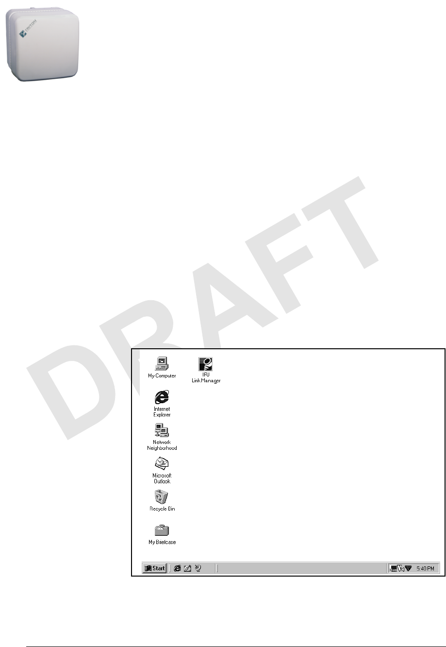
Desktop
The screen (Figure 1-1) that displays after you turn on the computer
and the power-on and login processes are complete.
Figure 1-1. Computer Desktop
Working with a Windows- based Application
1-2 © 1999 Triton Network Systems, Inc. All Rights Reserved.
CONFIDENTIAL & PROPRIETARY
DO NOT COPY
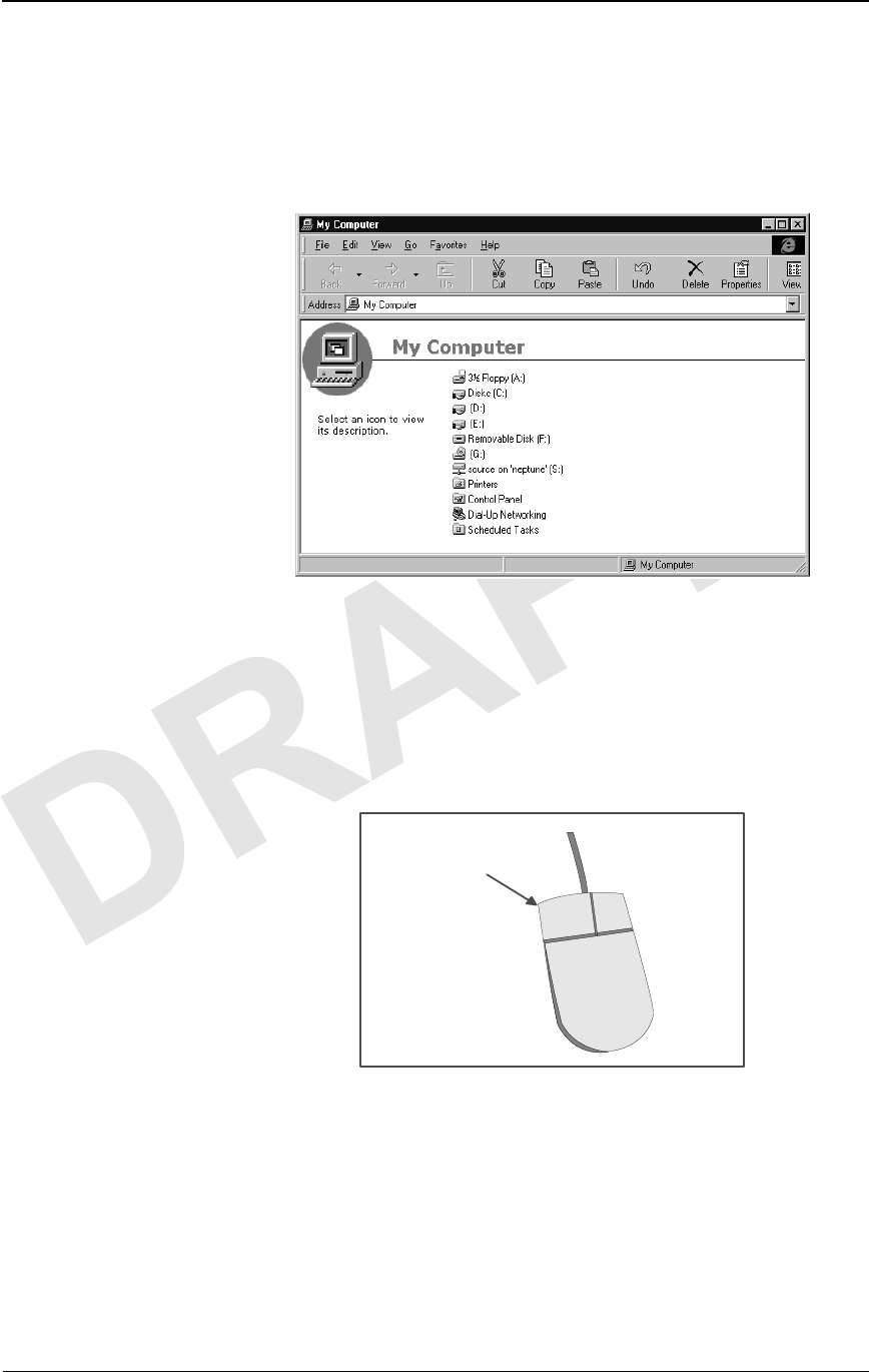
Window
A work area that displays on top of the desktop. This work area
enables you to run and display several applications simultaneously.
You can usually size a window to cover only a portion of the desktop
or fill the entire screen.
Figure 1-2. Sample Window
Mouse
A hand-held pointing device that enables you to select items in the
window. Your computer may have another form of pointing device
such as a trackball or pointing stick.
Figure 1-3. Typical Mouse
LEFT MOUSE
BUTTON

Looking at Windows
38 GHz Fast Ethernet Operations (9/9/99) - R0.1 1-3
CONFIDENTIAL & PROPRIETARY
DO NOT COPY
Graphical User Interface (GUI)
An interface that enables you to interact with a software application
through graphical elements, such as icons. A GUI can:
nProvide immediate feedback on actions taken
nProvide lists of valid values
nEnable you to make selections (instead of type responses)
nDisplay informational, error, and warning messages.
Looking at Windows
Each window is a GUI that is designed to guide you through a task as you
perform it. This section describes the items that appear in a GUI, enabling you
to enter data, make a selection, or initiate a system process.
NOTE: Depending on the type of system you are using (such as PC,
HP-Unix™, Solaris™), the GUIs you see may look slightly different
from the illustrations shown in this manual, which were captured
from a PC-based system.
IFU Link Manager uses two types of windows:
Frame
Top-level window that contains maximize, minimize, and close
buttons, and a title bar that you can click and drag to move the
window anywhere on your desktop. You can resize a frame window
as required.
Multiple Document Interface
Second-level window that displays only within the boundaries of a
top-level window. You can move or resize a multiple document
interface window only within those boundaries.
NOTE: Within the IFU Link Manager application, a multiple
document interface window displays only within the
boundaries of the WorkSpace window.
Working with a Windows- based Application
1-4 © 1999 Triton Network Systems, Inc. All Rights Reserved.
CONFIDENTIAL & PROPRIETARY
DO NOT COPY
Window Components
Figure 1-4 and Figure 1-5 show the components that are commonly available
on IFU Link Manager windows.
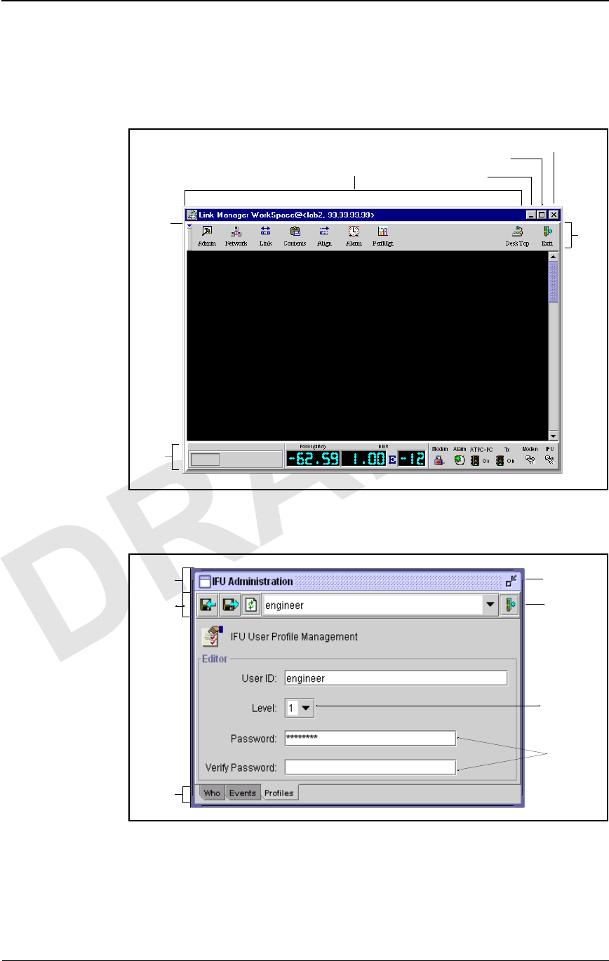
Figure 1-4. Sample Frame Window
Figure 1-5. Sample Multiple Document Interface Window
Title Bar
Tool
Bar
Status
Bar
Latch
Bar
Minimize Button
Maximize Button Exit Button
Title Bar
Text Fields
Exit Button
Minimize
Button
Combo Box
Tabs
Tool Bar

Looking at Windows
38 GHz Fast Ethernet Operations (9/9/99) - R0.1 1-5
CONFIDENTIAL & PROPRIETARY
DO NOT COPY
Table 1-1 provides a description of the window components called out in
Figure 1-4 and Figure 1-5.
Table 1-2 describes components you may find in applications that are not
specifically called out in Figure 1-4 or Figure 1-5.
Table 1-1. Window Components
Component Description
Combo Box Text box that enables you to select from a list of
valid values or options. The process to display the
values depends on the GUI. If the field shows a
down arrow, click the arrow to display the list;
otherwise, click in the box to display the list. With
the list displayed, use the scroll bar or click to
select the required value or option.
Exit Button Closes the window and removes it from the screen.
Latch Bar Enables you to hide the tool bar. To redisplay the
toolbar, click the latch bar again.
Maximize Button Enlarges the window to fill your desktop. After
maximizing the window, the button display
changes to show two windows. Click the button
again to return to the original window size.
Minimize Button Reduces the size of the window to an icon on your
desktop.
Status Bar (Frame window only) Indicates whether alarms are
on or off.
Tab Shows an individual “page” within a window.
Click a tab to view its page.
Text Field Area in which you type information. Text fields
can be programmed to accept letters, numbers, or a
combination of both.
Title Bar Displays the name of the window.
Tool Bar Contains buttons that enable you to initiate system
processes such as closing a window, saving a
record, and printing.
Table 1-2. Additional Window Components
Component Description
Button Small box that provides a shortcut for a command.
A button can contain an icon and/or text to
represent the shortcut.

Working with a Windows- based Application
1-6 © 1999 Triton Network Systems, Inc. All Rights Reserved.
CONFIDENTIAL & PROPRIETARY
DO NOT COPY
Display-Only Components
Display-only components appear dimmed or “grayed-out.” You cannot select
or type information in a display-only component. Components are
display-only when they are not necessary for performing a task or because
they access function that are not available.
Working with Windows
This section describes the basics of using Windows including:
nMoving windows
nBringing a window forward
nResizing windows
Moving a Window
You can move windows on your desktop to better accommodate your work
area. To move a window, click the title bar and drag the window to where you
want it to display on your desktop. When the window is positioned
appropriately, release the mouse button.
NOTE: You cannot move a multiple document interface window
outside the boundaries of the WorkSpace window.
Check Box Open box that provides the ability to enable or
disable a function. When a check box is deselected,
no mark displays in it. When it is selected, a check
mark displays in the box.
Icon Pictorial representation of a window, menu, or
system process such as closing a window, saving a
record, or printing. A button can contain an icon to
symbolize a system process.
Save Button Saves information you typed in the window.
Window Pull-Down
Menu Button (Frame window only) Displays a list of options.
These options enable you to perform actions such
as closing the window, resizing the window, and
minimizing the window.
Table 1-2. Additional Window Components
Component Description

Looking at Windows
38 GHz Fast Ethernet Operations (9/9/99) - R0.1 1-7
CONFIDENTIAL & PROPRIETARY
DO NOT COPY
Bringing a Window Forward
As you move windows, you may find you are laying them on top of each
other, hiding information you need to see. To bring a window into the
foreground to work in it, click on any exposed part of the window.
NOTE: You may have to move overlaying windows before you can
click on the window you want in the foreground.
Resizing a Window
You can also change the size of windows by performing one of the following
tasks:
nMove the mouse pointer to the upper left or right corner of the
window (until the pointer becomes a double arrow) and then drag the
corner of the window until it is the desired size.
nUse the window pull-down menu and select to resize the window.
nClick the maximize button or the minimize button in the upper right
corner of the window.

Working with a Windows- based Application
1-8 © 1999 Triton Network Systems, Inc. All Rights Reserved.
CONFIDENTIAL & PROPRIETARY
DO NOT COPY

38 GHz Fast Ethernet Operations (9/17/99) - R0.1 2-1
CONFIDENTIAL & PROPRIETARY
DO NOT COPY
2IFU Link Manager
Overview
This chapter provides:
nA description of IFU Link Manager
nSystem requirements
nSample illustrations of some of the basic windows within IFU Link
Manager
nAn overview of the IFU Link Manager features
What Is IFU Link Manager?
IFU Link Manager is a software application that enables a crafts person to set
up, configure, and maintain IFUs in a network. The IFU Link Manager
application can be run locally (that is, at the installation site on a PC
connected directly to the IFU), or it can be operated remotely, from any point
in the IFU network including the Network Operations Center (NOC).
IFU Link Manager Overview
2-2 © 1999 Triton Network Systems, Inc. All Rights Reserved.
CONFIDENTIAL & PROPRIETARY
DO NOT COPY
Using a Local On-Site Connection
The on-site local connection method is shown in Figure 2-1. When connected
locally, IFU Link Manager works on either a single IFU or a single link at a
time.
Figure 2-1. IFU Link Manager On-Site Connection
IFU Link Manager enables you to perform local configuration monitoring and
limited network management operation of a radio link between two IFUs (one
near IFU and one far IFU). Using IFU Link Manager, you can monitor IFU
configuration parameters, provisioning and inventory information, security
and administration data, and alarms/faults.
34567
Far-End IFU
Near-End IFU
PC with
IFU Link Manager
What Is IFU Link Manager?
38 GHz Fast Ethernet Operations (9/17/99) - R0.1 2-3
CONFIDENTIAL & PROPRIETARY
DO NOT COPY
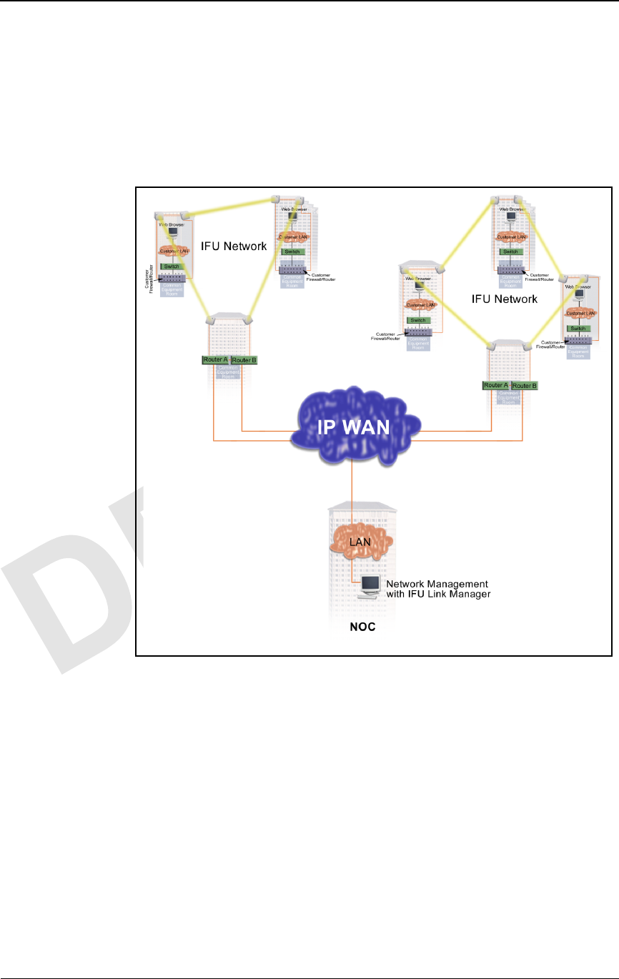
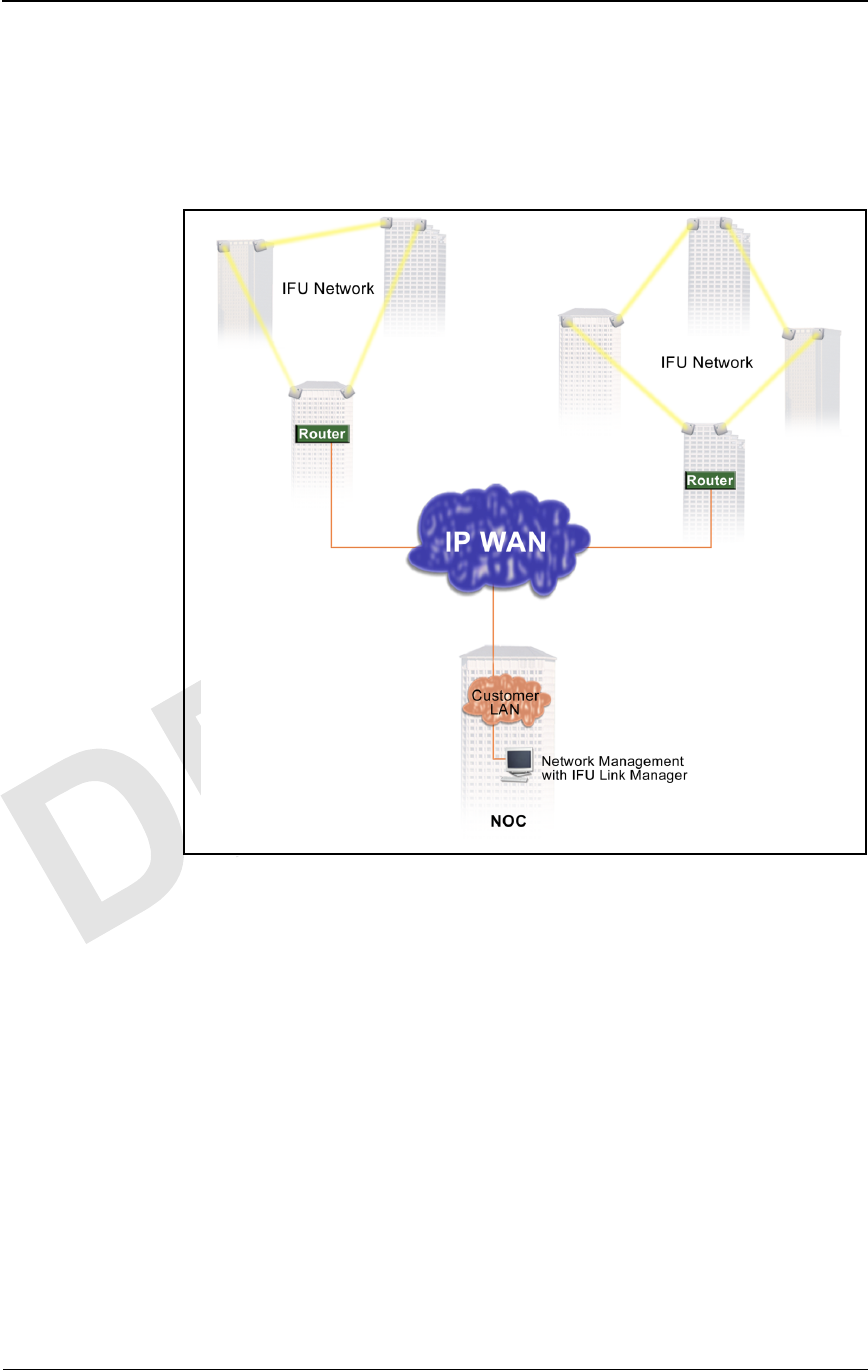
Using a Network Connection
IFU Link Manager enables you to perform continuous monitoring of IFUs in
your network without actually logging in to each IFU. By remotely
connecting a network management system to the managed elements, you can
monitor the status of the IFUs in your network. Figure 2-2 shows a typical
Internet network management system that uses IFU Link Manager.
Figure 2-2. Internet Network Management System Using IFU Link
Manager

IFU Link Manager Overview
2-4 © 1999 Triton Network Systems, Inc. All Rights Reserved.
CONFIDENTIAL & PROPRIETARY
DO NOT COPY
System Requirements
Install the IFU Link Manager software on a UNIX workstation or a personal
computer (PC), preferably a laptop (for connecting on-site).
Operating System requirements
The IFU Link Manager application runs on any OS that supports Sun
Microsystems Java™ Runtime Environment (JRE) version 1.1.6.
The following operating systems have been tested:
nMicrosoft Windows 95, 98, and NT 4.0 (JRE is not supported on
Windows 3.5.1 or below.)
nSun Solaris 2.5.1 and 2.7
Hardware requirements
To run IFU Link Manager, your PC must have the following
minimum features:
n200 MHz processor
n128 MB RAM
n1 GB of free hard disk space
nSVGA monitor
n10BaseT Ethernet network interface card
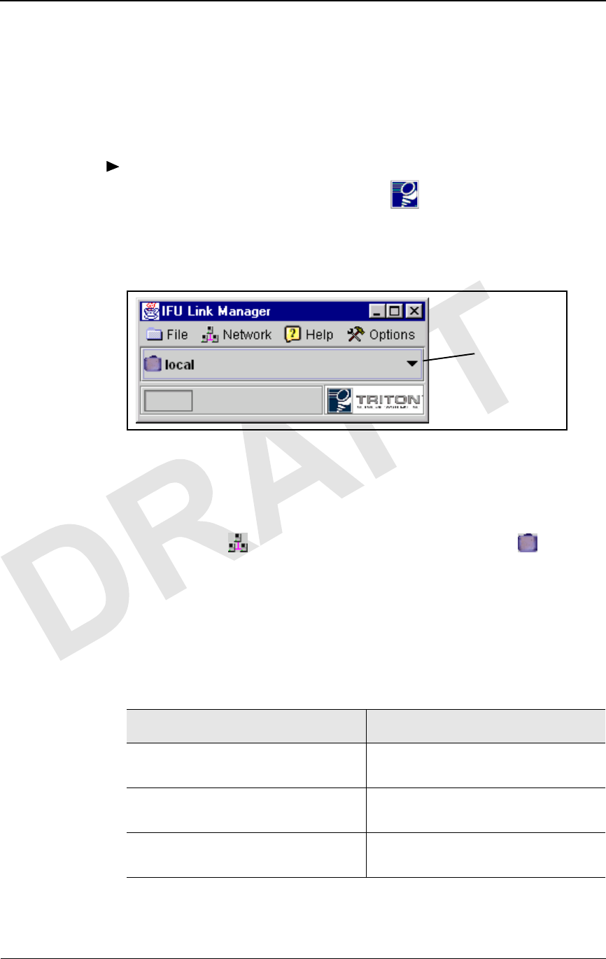
Looking at IFU Link Manager
When you access IFU Link Manager from the desktop, the first window that
displays is the IFU Link Manager main window (Figure 2-3), which is your
link to the IFUs in the network.
Figure 2-3. IFU Link Manager Main Window
IFU Link
Manager
Toolbar
IFU Tree
Combo Box
Looking at IFU Link Manager
38 GHz Fast Ethernet Operations (9/17/99) - R0.1 2-5
CONFIDENTIAL & PROPRIETARY
DO NOT COPY
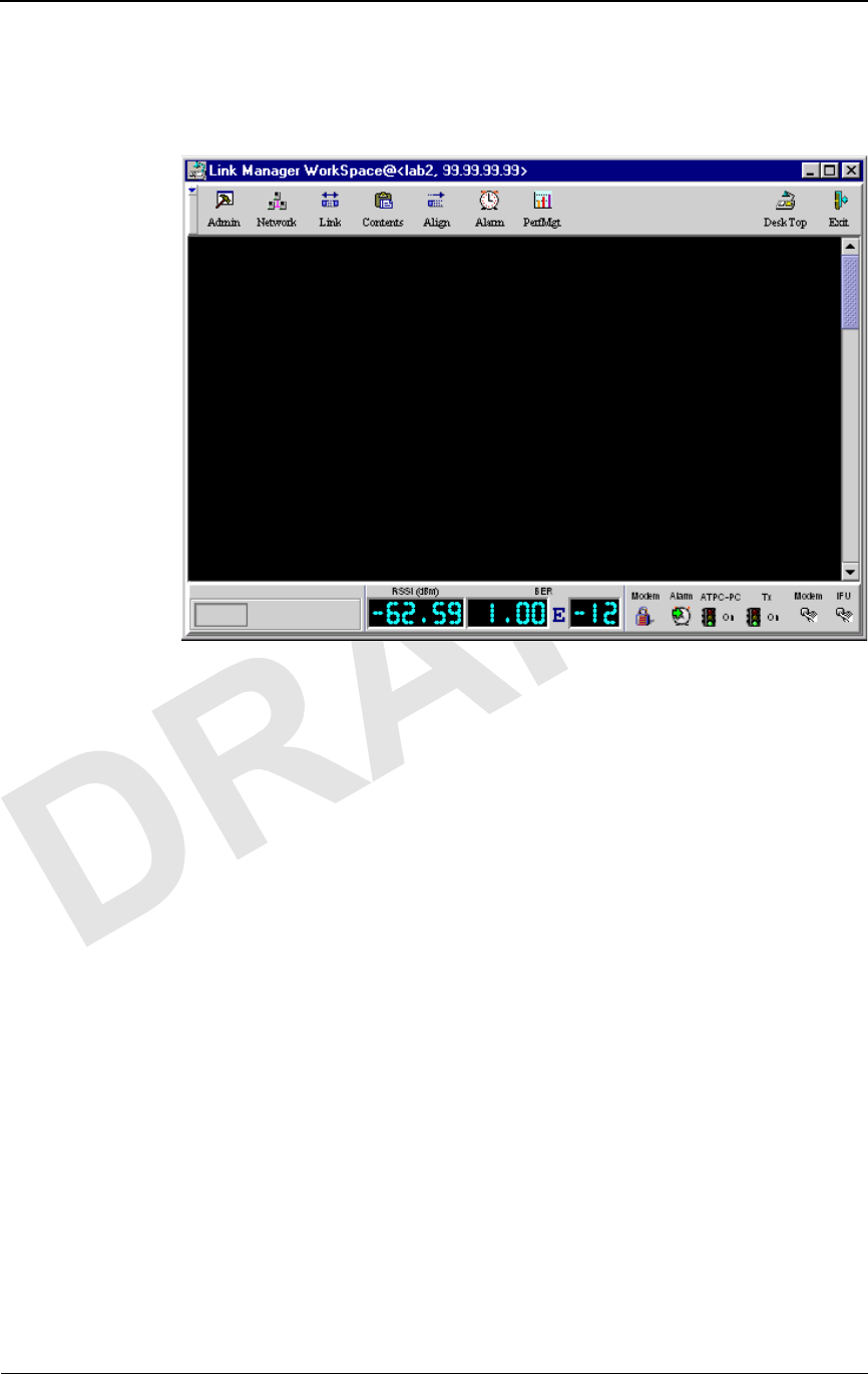
When you connect to an IFU from the main window, the IFU Link Manager
WorkSpace (Figure 2-4) opens. Other windows display as you perform
operations on an IFU in the network.
Figure 2-4. IFU Link Manager WorkSpace
NOTE: Refer to the online help for information about using IFU
Link Manager.
IFU Link Manager Overview
2-6 © 1999 Triton Network Systems, Inc. All Rights Reserved.
CONFIDENTIAL & PROPRIETARY
DO NOT COPY
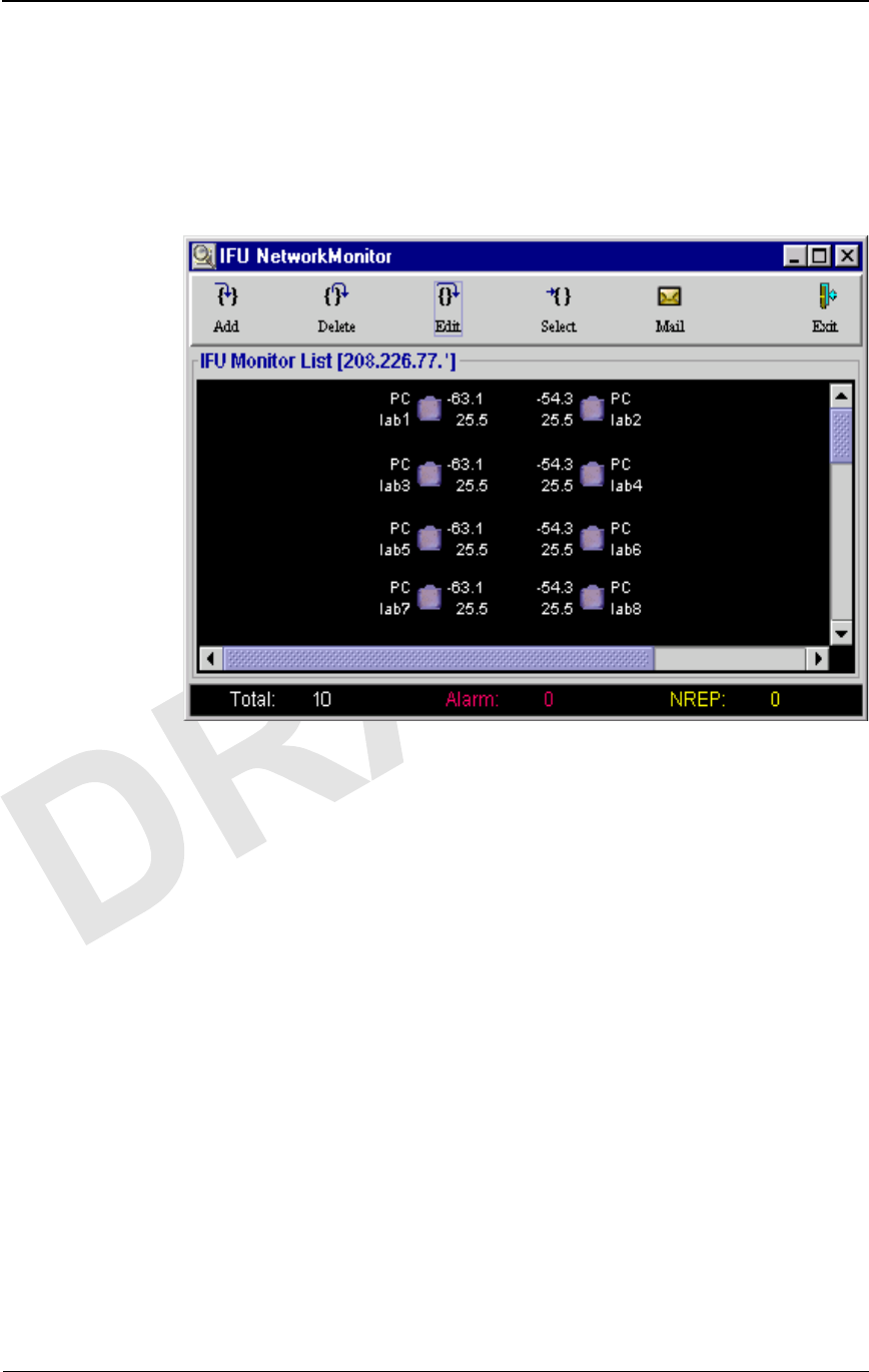
Looking at the NetworkMonitor Window
The IFU NetworkMonitor window enables the operator to view a network of
IFUs and quickly identify any problems in the network using IP masks
(defined subset of IFUs). You open a new NetworkMonitor window for
each IP mask you want to monitor.
Figure 2-5. IFU NetworkMonitor Window
The IFU NetworkMonitor window consists of multiple rows of linked IFU
pairs. The following information displays for each IFU:
nPower control status
nIP address or alias
nAlarm status
NOTE: If an alias is defined for the IFU, the alias displays;
otherwise, the IP address displays.
nReceived Signal Strength Indicator, RSSI
nSignal Quality Metric, SQM
Additionally, the status bar at the bottom of the window shows:
nTotal number of IFUs being monitored
nNumber of IFUs with active alarms
nNumber of IFUs that are not currently reporting

Feature Overview
38 GHz Fast Ethernet Operations (9/17/99) - R0.1 2-7
CONFIDENTIAL & PROPRIETARY
DO NOT COPY
Feature Overview
IFU Link Manager features include:
nSecurity Management
nIFU Configuration Management
nFault Management
nRF Performance Management
nIFU Network Management
nAutomatic Transmit Power Control
nTransmitter Power
nManual Reboot
NOTE: Refer to the online help for detailed information about fields
on each screen.
Security Management
The Security Management feature enables you to:
nRestrict access to the IFU to authorized users only. The security
access levels are:
Level 1
Full read and write access
Password administration capability
Network administration capability
Level 2
Full read and write access
No network or password administration capability
Level 3
Read only access
nDefine up to 10 user login profiles by a user with Level 1 access
nControl access to the Configuration, Fault, and Performance
Management functions based on the user’s login security level
nAdminister access passwords only by a user with Level 1 access
nView the following information via IFU Link Manager:
½All users currently connected to an IFU
½A log of the last 10 user events for an IFU
Each IFU allows up to two simultaneous login sessions.

IFU Link Manager Overview
2-8 © 1999 Triton Network Systems, Inc. All Rights Reserved.
CONFIDENTIAL & PROPRIETARY
DO NOT COPY
NOTE: For more information about this feature, refer to “Security
Management” in the online help.
IFU Configuration Management
Depending on your level of access (see For more information about this
feature, refer to “General Procedures” in the online help. on page 2-13), the
Configuration Management feature enables you to enter or review the
following characteristics of the IFU:
nSite name, IP addresses of IFU pairs
NOTE: To monitor the status of an IFU with IFU Link
Manager, you must enter the correct addresses for each IFU
in a linked pair.
nAssigned channel, rain region, grade of service, latitude and longitude
of IFU pairs
nInstallation, in-service, and last change dates
IFU configuration monitoring enables you to review the following
characteristics of the IFU:
nInventory information (IFU serial number, IFU product type, IFU
Link Manager software version)
nLink selection, antenna orientation, and type of network interface
NOTE: For a list of the specific parameters that can be changed or
viewed, refer to “IFU Provisioning” in the online help.
Fault Management
The Fault Management feature provides the following functions:
nEnables the user to view an IFU’s active alarms with time stamps as
they are stored on each IFU
nEnables the user to tag a note to each alarm type
nEnables the user to view the Alarm History Log that includes the
previous 300 time stamped events (set, event, and clear) as they are
stored on each IFU
nEnables the user to mask and unmask all alarms
nEnables the user to change the threshold setting for modem power,
SQM, and internal temperature

Feature Overview
38 GHz Fast Ethernet Operations (9/17/99) - R0.1 2-9
CONFIDENTIAL & PROPRIETARY
DO NOT COPY
nDisplays the modem lock status on the WorkSpace window
Alarms
The operator can program the system to automatically send an e-mail message
to a programmable valid destination when the status of an IFU status changes
to not reporting (NREP), alarmed, or when the alarm clears.
Table 2-1 lists the alarms that can display in IFU Link Manager and identifies
possible problem areas that may have caused each alarm. You also can view
the list of alarms on the Discrete tab of the Alarms window.
NOTE: Critical severity indicates that the IFU cannot be used; major
severity indicates that the IFU may still be functioning.
Table 2-1. Alarms
Alarm Default
Severity Affected
Subassembly Description
EXCITER UNLOCK Critical Exciter and/or
Reference Oscillator Exciter reports loss-of-lock condition,
which means that the IFU lost its ability
to transmit valid payload and OAM&P
data across the RF link.
LOL SONET
CLOCK Critical Modem and/or NIC The modem cannot identify a locked
SONET clock (loss of lock) from the data
received from the modem. Therefore, any
data received via the RF link is no longer
valid.
NOTE: This alarm displays only on the
Discrete tab of the Alarms window.
MODEM UNLOCK Critical Modem The demodulation functional components
of the modem have lost lock to the
incoming signal. The data received
through the RF link is not valid.
NOTE: This condition can be due to a
heavy rain interruption, in which case it
will correct itself when the rain subsides.
PAYLOAD OFFLINE Critical Modem and/or NIC IFU stopped transmitting and transporting
payload data because it is receiving too
many errors for the modem to correct.
POWER TX RAIL Critical Power Supply Unit Power supply to the transmitter failed.
The IFU is not transmitting data across
the RF link to its paired IFU.

IFU Link Manager Overview
2-10 © 1999 Triton Network Systems, Inc. All Rights Reserved.
CONFIDENTIAL & PROPRIETARY
DO NOT COPY
POWER UNSWITCH
RAIL
Critical Power Supply Unit Power failed to at least one of the IFU
major subassemblies other than the
transmitter.
TX FAIL Critical Transmitter The RF transmitter failed. The IFU
cannot transmit valid data across the IFU
link to its paired IFU.
CARRIER
FREQUENCY OFFSET
Major Modem The carrier frequency is approaching the
modem lock limit.
GPI 1 Major External External equipment reports an event.
GPI 2 Major External External equipment reports an event.
IF TUNING FAIL Major Modem The required Invisible Fiber™
compensation is outside of the allowable
range.
INTERNAL COMM
FAIL
Major Modem, NIC, and/or
Power Supply Unit Communication between the CPU and at
least one of the internal subcomponents
failed.
INTERNAL
TEMPERATURE HIGH
Major IFU Internal temperature of the IFU is
approaching the upper operational limit of
the IFU as set during configuration.
INTERNAL
TEMPERATURE LOW
Major IFU Internal temperature of the IFU is
approaching the lower operational limit of
the IFU as set during configuration.
LOS SONET FIBER Major NIC Loss of Signal (LOS) is detected from the
user data optical fiber input port.
NOTE: This alarm displays only on the
Discrete tab of the Alarms window.
MODEM POWER
LOW
Major Modem Modem power is approaching the
minimum operational level of the IFU as
set during configuration.
POWER +12V RAIL Major Power Supply Unit The +12 V rail of the power supply unit is
operating outside of its specification.
POWER – 48V RAIL Major Power Supply Unit The – 48 V rail of the power supply unit is
operating outside of its specification.
POWER MNGMT
TIMEOUT
Major CPU A timeout occurred before the power
control logic received a message across
the RF link from the paired IFU.
Table 2-1. Alarms
Alarm Default
Severity Affected
Subassembly Description

Feature Overview
38 GHz Fast Ethernet Operations (9/17/99) - R0.1 2-11
CONFIDENTIAL & PROPRIETARY
DO NOT COPY
NOTE: For more information about this feature, refer to “Fault
Management” in the online help.
RF Performance Management
The RF Performance Management feature enables IFU Link Manager to
display the following data for each IFU:
nRSSI
nSQM
nBit Error Rate (BER)
nInternal temperature of the IFU
Additionally, IFU Link Manager displays the following types of Performance
Management data in a graphical format:
nRF: SQM and modem power
nIFU: Block errors, modem lock status, and internal temperature
NOTE: For more information about this feature, refer to
“Performance Management” in the online help.
IFU Network Management
IFU Link Manager can be used to monitor your IFU network provided the
IFUs are configured to enable network management from this workstation.
Using this feature, you can monitor the IFUs in a network without logging in
to each IFU.
SQM LOW Major Modem The received (SQM) level is approaching
the minimum operational level of the IFU
as set during configuration.
TX ID MISMATCH Major IFU The IFU received a transmission across
the RF link from a source other than its
paired IFU.
TX POWER MAX Major IFU The transmitter is currently transmitting
at the maximum level. A rain interruption
or link block can cause this situation.
Table 2-1. Alarms
Alarm Default
Severity Affected
Subassembly Description

IFU Link Manager Overview
2-12 © 1999 Triton Network Systems, Inc. All Rights Reserved.
CONFIDENTIAL & PROPRIETARY
DO NOT COPY
Use HP OpenView to monitor the network and perform standard network
management functions. Use IFU Link Manager to perform the following IFU
specific management functions on IFUs:
nSecurity
nConfiguration
nFault
nPerformance
You can launch multiple Network Monitor windows (Figure 2-5 on page 2-6)
with each window monitoring multiple IFU links (partitioned by IP address
filtering).
You can use HP OpenView to assist with your net management function.
Automatic Transmit Power Control
Automatic Transmit Power Control (ATPC) enables the IFU to maintain a
constant receive signal at the lowest appropriate power. The IFU operates
between –30 and –70 dBm.
The ATPC feature allows the user to enable or disable the ATPC and displays
the status on the WorkSpace window. When power control is enabled, the
display shows a green light on the ATPC icon. Conversely, when power
control is disabled the display shows a red light on the ATPC icon.
NOTE: Generally, you will want to disable ATPC only when you are
aligning the antennas. For more information about using this feature,
refer to? in the online help.
Transmitter Power
The Transmitter Power feature enables the user to power the transmitter ON
and OFF. The transmitter status displays on the workspace.
NOTE: For more information about this feature, refer to “General
Procedures” in the online help.
Manual Reboot
The Manual Reboot feature enables the user to reboot the modem or the IFU.

Feature Overview
38 GHz Fast Ethernet Operations (9/17/99) - R0.1 2-13
CONFIDENTIAL & PROPRIETARY
DO NOT COPY
NOTE: For more information about this feature, refer to “General
Procedures” in the online help.

IFU Link Manager Overview
2-14 © 1999 Triton Network Systems, Inc. All Rights Reserved.
CONFIDENTIAL & PROPRIETARY
DO NOT COPY

38 GHz Fast Ethernet Operations (9/13/99) - R0.1 3-1
CONFIDENTIAL & PROPRIETARY
DO NOT COPY
3IFU System Basics
This chapter provides the following information:
nProcedure for loading the IFU Link Manager software
nIFU OAM&P network connectivity description
nProcedure for accessing IFU Link Manager
nProcedure for accessing online help from within IFU Link Manager
Software Installation
The IFU Link Manager can be installed on a UNIX workstation, PC, or laptop
for local or remote access to IFUs. Triton Network Systems, Inc., personnel
install software on your computers as required.
Configuring Software for Remote Access
You can access an IFU remotely via IFU Link Manager. Refer to “General
Procedures” the online help for information about configuring IFU Link
Manager to receive information from a remote IFU.
Connecting the Equipment
You can connect the IFU locally to the PC at the site or via a LAN connection
to the Network Operations Center (NOC).
IFU System Basics
3-2 © 1999 Triton Network Systems, Inc. All Rights Reserved.
CONFIDENTIAL & PROPRIETARY
DO NOT COPY
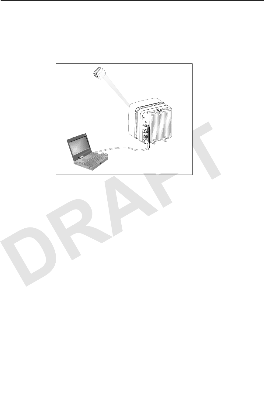
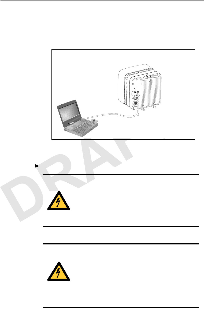
Connecting Locally
You use the IFU test cable to connect the PC’s 10BaseT Ethernet network
interface card to the IFU’s Local Ethernet (test) connector, as shown in
Figure 3-1.
Figure 3-1. Connecting the PC to the IFU
1 To connect the PC to the IFU:.
DANGER – HIGH VOLTAGE HAZARD: Do not work
on the system or connect or disconnect cables during
periods of lightning activity, rainy weather, or both.
DANGER – L’HASARD DU TENSION ÉLEVÉ : Ne
pas travailler sur le système ni brancher ni débrancher les
câbles durant l’activité de la foudre, par de temps
pluvieux, ou tous le deux.
DANGER – HIGH CURRENT HAZARD: Do not turn
on power before reading the Triton Network Systems’
product documentation. This device has a – 48 Vdc
(4 amps operating peak per feed) direct current input.
DANGER – L’HASARD DU COURANT ÉLEVÉ : Ne
pas mettre la tension avant de lire la documentation du
produit fournie par la société Triton Network Systems. Cet
appareil a une alimentation directe de – 48 V CC (courant
de pointe de 4 ampères par ligne d’alimentation).
34567
D
C
B
E
F
G
IFU
IFU LINK MANAGER
TEST
CABLE

Connecting the Equipment
38 GHz Fast Ethernet Operations (9/13/99) - R0.1 3-3
CONFIDENTIAL & PROPRIETARY
DO NOT COPY
1Connect the IFU test cable to the test port of the IFU.
2Connect the RJ-45 plug of the test cable to the laptop
3Turn the power switch on the PC to the ON position.
CAUTION: Beware! Radio transmitter is ON when the
red light indicator on back side of Invisible Fiber™ Unit is
illuminated. Observe all radio frequency energy exposure
and service interruption cautions.
MISE EN GARDE : Attention ! Le poste émetteur est EN
MARCHE lorsque le témoin rouge sur le dos de l’unité
Invisible FiberMD est allumé. Respecter toutes les mises en
garde concernant l’exposition aux radiofréquences et
l’interruption de service.
WARNING – RF EXPOSURE HAZARD: Ensure the
safety of all personnel. Do not stand in front of the
Invisible Fiber™ unit (antenna) in order to avoid possible
harmful radio frequency energy exposure. Serious bodily
injury may result.
MISE EN GARDE – RF EXPOSURE HAZARD :
Assurer la sécurité de tout le personnel. Ne pas rester
debout devant l’unité Invisible FiberMD (l’antenne) afin
d’éviter toute exposition dangereuse aux radiofréquences.
Les lésions corporelles serieux s’ensuivre.
IFU System Basics
3-4 © 1999 Triton Network Systems, Inc. All Rights Reserved.
CONFIDENTIAL & PROPRIETARY
DO NOT COPY
Connecting via a NOC
IFU Link Manager can perform OAM&P functions from a remote location
such as a NOC. You connect a PC with IFU Link Manager from the NOC to
an IFU network via an IP WAN network set as illustrated in Figure 3-2.
Figure 3-2. OAM&P Connectivity from NOC
Accessing IFU Link Manager
38 GHz Fast Ethernet Operations (9/13/99) - R0.1 3-5
CONFIDENTIAL & PROPRIETARY
DO NOT COPY
Accessing IFU Link Manager
You access the IFU Link Manager to set up your network view, to work on a
specific IFU, or to monitor a network of IFUs.
To access the IFU Link Manager application:
Double-click the IFU Link Manager icon ( ) on the PC desktop or the
icon assigned to an IFU from HP OpenView™.
Result: The IFU Link Manager main window (Figure 3-3) opens on the
desktop.
Figure 3-3. IFU Link Manager Main Window
IFU Link Manager provides a graphical representation of your IFU network
containment hierarchy in a tree structure showing clusters of IFUs as branches
(represented by ) and single IFUs as leaves (represented by ). You can
set up a unique view on your PC to see only the elements you need to work
on. When the window first opens, the tree is collapsed, but you can expand it
by clicking the drop-down selection button.
Table 3-1 identifies the tasks you can perform from the Network drop-down
menu.
Table 3-1. Network Tasks
To... Refer to...
Add a network element “Adding a Network Element” in the
online help
Delete a network element “Deleting a Network Element” in the
online help
Edit a network element “Editing a Network Element” in the
online help
Combo Box

IFU System Basics
3-6 © 1999 Triton Network Systems, Inc. All Rights Reserved.
CONFIDENTIAL & PROPRIETARY
DO NOT COPY
Additional IFU Link Manager Functions
The IFU Link Manager incorporates five separate tools:
IFU Navigation
This tool allows an operator to navigate through the network to the
IFU of interest, and then invoke a network management session with
the IFU. Once a session connection occurs, a workspace is created
within the GUI, along with a toolbar with the four tools for IFU
management.
IFU Administration
This tool enables the operator to:
nList users currently logged into the IFU
nLog users that have been logged into the IFU since it was
initialized
nAdminister IFU access passwords
IFU Attributes
This tool allows the operator to manage all pertinent information
related to the IFU in four categories:
nGeneral: site name, IFU address, EMS address, installation date.
nAs-built factory settings: A or B radio, antenna polarization (Tx
horizontal or vertical), link type (SONET OC-3 or Fast Ethernet).
nLink: RF channel number, rain region of operation, desired grade
of service, link end-point latitude and longitude coordinates.
After these parameters are entered, the tool calculates whether the
desired grade of service can be achieved, and what the expected
fair weather modem power signal level should be.
nInventory: serial, model, and version numbers for the IFU, and
serial numbers for internal components.
Alarm Count and Navigation
This tool provides three different functions:
Connect to a network element to
configure the IFU or monitor the
network in which it resides
“Connecting to an IFU” in the online
help
Monitor the status of IFUs in a network “Monitoring Your Network” in the
online help
Table 3-1. Network Tasks
To... Refer to...

Online Help
38 GHz Fast Ethernet Operations (9/13/99) - R0.1 3-7
CONFIDENTIAL & PROPRIETARY
DO NOT COPY
nAlarm Level: current status of the IFU and its internally
configured alarms
nAlarm Log: history of alarms (occurrence, when cleared)
nGPI: status, configuration, and log of GPI inputs and outputs
Performance Management
This tool enables the operator to see how the system is performing by
offering a series of strip charts (showing current data as IFU Link
Manager collects it) and historical plots.
Using the performance management tool, the operator can view the
following strip charts:
nModem power and signal quality metric (SQM) data
nBlock errors, modem lock status, and temperature
nIFU temperature plus the Tx, +12 V and -48 V statuses
Additionally, the performance management tool enables the operator
to plot the following data:
nModem power defined by Received Signal Strength Indicator
(RSSI) in dB
nSQM in dB
nReed-Solomon block errors from the modem
nModem lock status in discrete values
nInternal temperature of the IFU
NOTE: Refer to the online help for more information about
performing these tasks.
Online Help
Two types of online help are available:
nTool tips – Short explanation of an icon or button.
nProcedure – Information that provides instructions for using the IFU
Link Manager to configure, administer, and maintain an IFU
IFU System Basics
3-8 © 1999 Triton Network Systems, Inc. All Rights Reserved.
CONFIDENTIAL & PROPRIETARY
DO NOT COPY
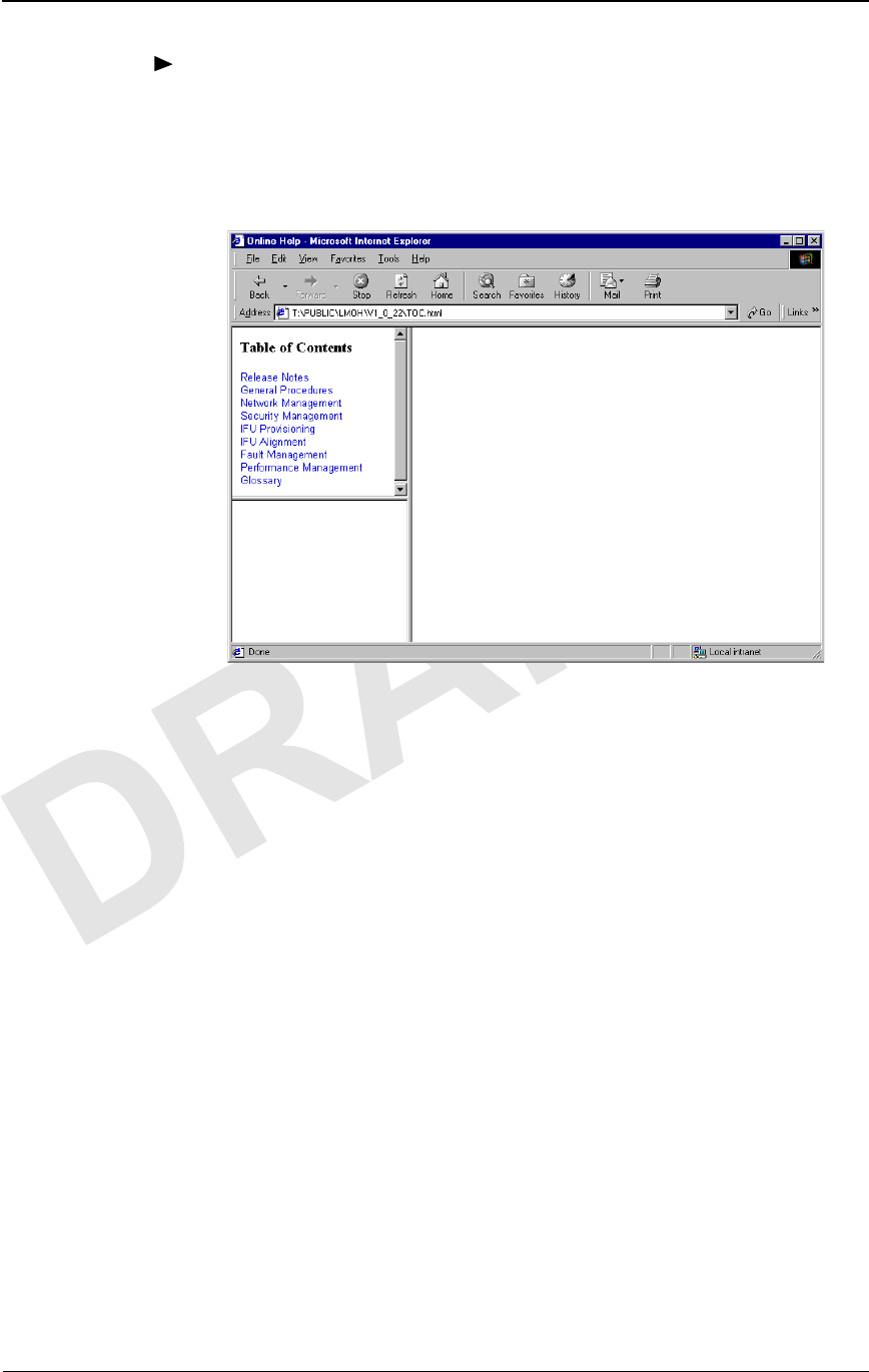
To access online help:
1Locate the IFU Link Manager help file, (IFU LM Help).
2Open the file. The online help table of contents displays as shown in
Figure 3-4.
Figure 3-4. IFU Link Manager Online Help

Product Glossary - R0.1 glossary-1
CONFIDENTIAL & PROPRIETARY
DO NOT COPY
Invisible Fiber™ Product
Glossary
10BaseFL
Part of the IEEE 802.1j standard for 10 Mbps Ethernet fiber.
10BaseT
IEEE 802.3 standard specifying Ethernet over unshielded twisted pair cables.
99.999% availability
(Also known as five 9s availability.) Amount of time the system is expected to
be available. If the system is available 99.999% of the time, expected down
time is approximately six minutes per year, derived as follows:
Days per year X hours per day X (100–99.999) ÷ 100 X 60 =
365.25 X 24 X (100–99.999) ÷ 100 X 60 = 5.2 minutes
100BaseFX
Part of the IEEE 802.3u standard for 100 Mbps Ethernet over fiber.
A
ABAM
A designation of Lucent Technologies for 22 gauge, 110 ohm, insulated,
twisted-pair cable used to connect an ADM switch to a T1 distribution panel.

glossary-2 © 1999 Triton Network Systems, Inc. All Rights Reserved.
CONFIDENTIAL & PROPRIETARY
DO NOT COPY
Add/Drop Multiplexer (ADM)
A device that provides an interface between the different signals in a digital
T-carrier or SONET network. When an ADM is inserted in a transmission
line, it enables lower rate signals to be extracted (dropped) and transported
differently (electrical or optical). Similarly, a lower rate signal can be inserted
(added) into a higher rate signal.
ADM
See Add/Drop Multiplexer (ADM).
AIS
See Alarm Indication Signal (AIS).
Alarm Indication Signal (AIS)
A special signal that is transmitted to downstream equipment for specific
equipment fault conditions.
antenna
A mechanical device that can convert electrical signals to and from
electromagnetic waves. An IFU contains an antenna.
Asynchronous Transfer Mode (ATM)
A cell-based protocol, developed by the ITU-T, for transmitting and
switching voice, video, and data traffic. ATM technology does not use a fixed
timing reference, hence the name asynchronous.
ATM
See Asynchronous Transfer Mode (ATM).
atmospheric absorption
Amount of energy lost when radio waves are transmitted due to the presence
of atmospheric gases.
attenuation
The reduction in the strength of a signal measured in dB. See also
propagation loss.
ADD/DROP
MULTIPLEXER
Signals added and dropped
at an intermediate point in
the transmission (via a
multiplexer)
Communication Flow

Product Glossary - R0.1 glossary-3
CONFIDENTIAL & PROPRIETARY
DO NOT COPY
azimuth
The horizontal angle the radiating lobe of an antenna makes. When you adjust
an IFU by its azimuth, you move it on its horizontal plane (left to right or right
to left).
B
backbone
A backbone is the transport path that provides connectivity to other paths. On
the Internet or a WAN, the backbone is a series of paths to which local,
regional, or global networks connect.
backhaul
A transmission path used to move traffic to/from a remote location from/to a
central location. (The verb form is back haul.)
bandwidth
The range of frequencies over which a signal is transmitted.
BER
See Bit Error Rate (BER).
Bit Error Rate (BER)
The number of bit errors detected – displayed as the ratio of the average
number of errored bits in a given number of bits sent. The BER is used to
measure transmission quality. For example, a BER of 10–12 is equivalent to
one error in a trillion bits, which means that for:
nSONET OC-3, one error bit is detected approximately every 1.8
hours
nFast Ethernet, one error bit is detected approximately every 2.8 hours.
BNC connector
Bayonet Neil-Concelman connector. A bayonet type of connector for coaxial
cables in an Ethernet network.
C
Central Office (CO)
Location at which one or more switches reside for aggregating voice or data
traffic.
Central Processing Unit (CPU)
Central controller that coordinates functions in the IFU.

glossary-4 © 1999 Triton Network Systems, Inc. All Rights Reserved.
CONFIDENTIAL & PROPRIETARY
DO NOT COPY
channel
Physical medium through which signals are transmitted. In optical fiber
transmissions, a channel is a separate wavelength of light within a combined
multiplexed light stream. An RF channel is the portion of the RF spectrum
used to carry data on a given frequency.
channelization
Logically subdividing a frequency (normally assigned by a regulatory agency
for the delivery of broadband wireless services).
Competitive Local Exchange Carrier (CLEC)
Independent company that competes with the already established local
telephone company by providing its own network and switching. CLEC
distinguishes a new or potential competitor from an established local
exchange carrier (LEC). The term originated from the Telecommunications
Act of 1996, which was intended to promote competition among
long-distance and local phone service providers.
CO
See Central Office (CO).
cochannel interference
Interference between signals transmitted within one radio frequency channel.
colocation
Space set aside for a customer’s telecommunications equipment on the
service provider’s premises. For example, a web site owner could place its
computer server on the premises of an ISP, or an ISP could locate its network
router at a company that supplies switching services to other ISPs.
Competitive Local Exchange Carrier
See Competitive Local Exchange Carrier (CLEC).
commissioning
Tasks required to enable equipment to be placed in a live network. IFU
commissioning tasks include configuration and antenna alignment.
configuration management
The process of setting equipment attributes that enables equipment to function
as intended.
consecutive point
Network architecture implemented via a point-to-point-to-point design.
CPE
See Customer Premise Equipment (CPE).

Product Glossary - R0.1 glossary-5
CONFIDENTIAL & PROPRIETARY
DO NOT COPY
CPU
See Central Processing Unit (CPU).
Crane rain model
System of formulas, charts, and maps developed by Dr. Robert K. Crane to
depict a global prediction of attenuation caused by rain. See also rain
attenuation.
Customer Premise Equipment (CPE)
Equipment (such as telephones and computers) installed at a customer’s site.
customer site
Network equipment configuration for a location at which network access is
provided in a carrier’s consecutive point network.
D
dB
Decibel. The unit of measurement for signal strength, usually the ratio
between a transmitted signal and a standard signal source.
decibel (dB)
See dB.
demarcation point
Logical dividing point between equipment and a network.
E
Element Management System (EMS)
Software application used to manage network equipment.
EMS
See Element Management System (EMS).
Ethernet
Generic term for the IEEE 802.3 standard network transmission protocol.
exciter
An oscillator that enables a tuner to change its frequency.
F
fade margin
Amount of signal reduction a receiver can tolerate and continue to maintain
satisfactory performance.

glossary-6 © 1999 Triton Network Systems, Inc. All Rights Reserved.
CONFIDENTIAL & PROPRIETARY
DO NOT COPY
far-end IFU
a) IFU at the other end of the link in the network (during site evaluation).
b) Second IFU installed in a linked pair of IFUs.
See also near-end IFU.
Fast Ethernet
Generic term for a IEEE standard network 100 Mbps transmission protocol.
fault management
Software that reports and identifies the source of network faults.
fiber optics
Technology in which information is transmitted as light impulses from one
point to another through extremely thin glass or plastic wire or fiber.
fixed wireless system
Communication system that uses radio spectrum to provide services to
locations that are not mobile.
forward error correction
A system in which redundant information is generated at the transmitted end
so that the receiving unit can detect, locate, and correct any errors before
delivering the transmission.
free space propagation loss
Normal signal attenuation of radio waves transmitted through free space. Free
space loss increases logarithmically with increased hop distance.
Fresnel zone
A defraction zone around the line-of-sight path between two points as shown
in the following illustration.
The line-of-sight, including the Fresnel zone, must be clear of obstructions to
ensure communication between the IFUs.
2 Miles
Fresnel Zone

Product Glossary - R0.1 glossary-7
CONFIDENTIAL & PROPRIETARY
DO NOT COPY
G
gateway
A network point that aggregates traffic and acts as an entrance to another
network.
gateway site
Network equipment configuration for a location that aggregates customer
traffic in a consecutive point network for access to and from the Internet.
general purpose input/output
See GPIO.
GPIO
General Purpose Input/Output. Input/output ports on the IFU that provide
external control of equipment or detection and generation of external alarms.
Each IFU contains four GPIO ports (two input-only and two output-only).
H
histogram
A graphical representation of the distribution of a performance parameter.
hop distance
The distance between two communicating IFUs. One objective in network
design is to design link hop distances so that the RF path loss does not exceed
the path loss allowance for the required availability or grade of service.
HP OpenView™
Hewlett Packard’s network management product consisting of a suite of
software tools that enable network operations staff to manage the elements in
a network. HP OpenView Network Node Manager™ and the IFU Link
Manager software provide complete element management functions for an
IFU network.
hub
A location in a network where data is aggregated and forwarded to its
destination. A hub contains a switch and a router.
I
IFU
Invisible Fiber™ unit. Outdoor fixed-wireless device, designed to fiber-optic
specifications, that combines antenna, transceiver, modem, and controller
modules to transport high-bandwidth network-grade broadband telephony and
data services.

glossary-8 © 1999 Triton Network Systems, Inc. All Rights Reserved.
CONFIDENTIAL & PROPRIETARY
DO NOT COPY
IFU Link Manager
Triton Network Systems’ software application that provides fault,
performance, configuration, and security management functions, enabling
onsite technicians and network management staff to configure and monitor
IFUs.
ILEC
Incumbent Local Exchange Carrier. Generic term for the Regional Bell
Operating Company (RBOC) or local carrier that was providing local
telephone service when the Telecommunications Act of 1996 was enacted.
Incumbent Local Exchange Carrier
See ILEC.
indoor repeater site
Location used to extend a consecutive point network to enable future
customer access.
Internet Protocol
See IP.
Internet Service Provider (ISP)
An operator that provides its customers access to the Internet.
Invisible Fiber™ unit
See IFU.
IP
Internet Protocol. A connectionless network layer protocol used for
forwarding individual packets from one intermediate destination (typically a
router) to another on the way to their final destination.
ISP
See Internet Service Provider (ISP).
ITU rain model
System of formulas, charts, and maps developed the International
Telecommunication Union (ITU) to characterize rain attenuation.
J
Java™
A C++-like, object-oriented programming language, created by Sun
Microsystems and used to build client and server applications that run on any
hardware platform where a Java virtual machine resides.

Product Glossary - R0.1 glossary-9
CONFIDENTIAL & PROPRIETARY
DO NOT COPY
Java™ Runtime Environment
See JRE.
JRE
Java™ Runtime Environment. Software platform that enables Java
applications to execute. The IFU Link Manager software requires JRE.
Java™ virtual machine
Software, created for specific hardware platforms (microprocessors), that
interprets compiled Java code (bytecode) using the microprocessor’s set of
instructions. Java virtual machines enable any Java application (bytecode) to
run on any platform without requiring the programmer to rewrite or recompile
the application for each platform.
L
LAN
Local Area Network. Integrated data communication network (linking
computers and peripheral devices) designed to provide services to a closed
user community. See also MAN and WAN.
line-of-sight
Straight line of space between a transmitter and receiver. The space between a
transmitter and receiver must be clear of obstructions because the
transmission media (such as microwave, infrared, and laser) travel in a
perfectly straight line.
link angles
GPS (Global Positioning System) coordinates of the angle for an IFU linked
pair.
link budget
The sum of transmission gains and losses between transmitter and receiver.
The total should be equal to or less than the system gain. The link budget is
configured using the transmitted signal power, receiver sensitivity, and
antenna gains.
link manager
See IFU Link Manager.
LMDS
See Local Multipoint Distribution Service (LMDS).
Local Area Network (LAN)
See LAN.

glossary-10 © 1999 Triton Network Systems, Inc. All Rights Reserved.
CONFIDENTIAL & PROPRIETARY
DO NOT COPY
Local Multipoint Distribution Service (LMDS)
Broadband wireless spectrum over which telephony and data services are
delivered.
loop back
Directing signals back toward the transmitting device at some point along the
communications path. Used as a method for troubleshooting.
M
MAN
Metropolitan Area Network. Integrated data communication network within a
city. See also LAN and MAN.
Management Information Base
See MIB.
MIB
Management Information Base. A collection of statistics and variables
residing on an SNMP-managed device. The statistics allow collection of
performance data and the variables allow configuration of the device.
microwave radio
Device that uses microwave frequencies (3–300 GHz) for consecutive point
communication.
Millimeter Wave
See MMW.
MMIC
See Monolithic Microwave Integrated Circuit.
MMW
Millimeter Wave. The frequency range between 30 and 300 GHz.
modem
MOdulator, DEModulator. A device that converts between analog and digital
signaling.

Product Glossary - R0.1 glossary-11
CONFIDENTIAL & PROPRIETARY
DO NOT COPY
modulation
Act of encoding information onto a carrier signal.
Monolithic Microwave Integrated Circuit
Integrated circuit technology that provides two-watt linear power at the Tx
port of the RF power amplifier.
multimode fiber
Optical fiber designed to carry multiple carrier signals concurrently, each at a
slightly different reflection angle within core of the optical fiber. See also
single-mode fiber.
multiplexer
Device that aggregates traffic into a single medium.
N
NE
Network Element. Single piece of equipment in the network.
near-end IFU
a) IFU at the location being evaluated.
b) First IFU installed in a linked pair of IFUs.
See also far-end IFU.
Network Element
See NE.
Network Interface Card
See NIC.
network management
The policies, procedures, and tools that enable an operator to monitor and
manage network elements.
Network Management System (NMS)
Integrated, comprehensive system of equipment used for monitoring and
managing network elements.
Network Operations Center (NOC)
Location at which monitoring and management of a network might take place.
network provisioning
Act of configuring IFU network hardware and software to make the network
operational.

glossary-12 © 1999 Triton Network Systems, Inc. All Rights Reserved.
CONFIDENTIAL & PROPRIETARY
DO NOT COPY
NIC
Network Interface Card. Interface between physical transmitter layer and
modem.
NMS
See Network Management System (NMS).
NOC
See Network Operations Center (NOC).
NREP
Not REPorting. System status indicating the IFU is not reporting alarms
because an operator has suspended alarm reporting.
O
OAM&P
Operations, Administration, Maintenance, and Provisioning. Describes a
piece of equipment or personnel required to manage a network.
OC-3
Optical Carrier level 3. Optical signal designed to receive and transmit
SONET. A pure OC-3 SONET channel carries 155.52 Mbps.
OC-12
Optical Carrier level 12. Optical signal designed to receive and transmit
SONET. A pure OC-12 SONET channel carries 622.08 Mbps.
OC-48
Optical Carrier level 48. Optical signal designed to receive and transmit
SONET. A pure OC-48 SONET channel carries 2.4 Gbps.
operating system
See OS.
OS
Operating System. Program that loads when a computer is booted and
manages all the other applications in the computer.
outdoor repeater site
Location used to extend a consecutive point network.
P
password
A string of characters entered by a user, typically in a Login screen, to gain
access to a computer system.

Product Glossary - R0.1 glossary-13
CONFIDENTIAL & PROPRIETARY
DO NOT COPY
path loss allowance
The net amount of amplification given to the signal in an IFU link, including
margins for adequate received SNR and channel fading. In other words, path
loss allowance is equal to the system gain plus the antenna gains.
payload
User traffic transported over a network
Point Of Presence (POP)
Umbrella name referring to the location of the physical access point where
user traffic is aggregated.
polarization
Directional orientation of a radio wave electric field. Some radio
communication systems can exploit polarization differences to reduce
interference from nearby links.
POP
See Point Of Presence (POP).
power source
A separate unit or part of a circuit that supplies power to the rest of the circuit
or to a system.
propagation loss
Signal attenuation that occurs during transmission.
provisioning
Act of configuring the gateway routers and the site equipment to enable a
customer to receive service.
Q
QAM
Quadrature Amplitude Modulation. Transmitted signal defined by amplitude
and phase.
R
Radio Frequency (RF)
An electromagnetic wave frequency from approximately 3 KHz to
approximately 300 GHz. Includes the frequencies used for radio and
television transmission.
radio overhead
IFU communication channel in addition to the payload.

glossary-14 © 1999 Triton Network Systems, Inc. All Rights Reserved.
CONFIDENTIAL & PROPRIETARY
DO NOT COPY
rain attenuation
Transmit signal loss due to rain.
Received Signal Strength Indicator
See RSSI.
receiver
Telecommunication equipment device that captures and converts a
transmitted signal to the required format.
reference oscillator
A device that generates a precise radio frequency signal to be used as a
reference.
RF
See Radio Frequency (RF).
RF spectrum
Range of available radio frequencies.
router
A layer-3 physical device that aggregates and directs network traffic based on
TCP/IP.
RS-232
Recommended standard physical interface (connector) for electrical,
functional, and mechanical communication interfaces between computers,
terminals, and modems.
RSL
See RSSI.
RSSI
Received Signal Strength Indicator (also known as RSL, Received Signal
Level). A measured value from a receiver describing the received signal level
or strength.
S
security management
System to protect a network from invalid access.
Signal Quality Metric (SQM)
Ratio of bit energy to noise power spectral density. The SQM value relates to
transmission and receiver signal quality.

Product Glossary - R0.1 glossary-15
CONFIDENTIAL & PROPRIETARY
DO NOT COPY
Simple Network Management Protocol
See SNMP.
single-mode fiber
Optical fiber that allows only a single ray of light to propagate as a carrier. See
also multimode fiber.
site drawing
Graphic depiction, which shows the location of all IFU-related components
drawn by a contractor and designee. A site drawing is a component of a site
engineering folder.
site engineering folder
Documentation based on the information gathered during the site survey and
product requirement specifications.
SNMP
Simple Network Management Protocol. An industry standard protocol used to
communicate between elements and management systems in a network.
SONET
Synchronous Optical NETwork. Standard protocol that defines a group of
fiber-optic transmission rates that can transmit various bit-rate signals inside a
broadband synchronous signal. SONET was designed to allow for a
multi-vendor environment.
SNR
Signal-to-Noise Ratio. The SNR measures the quality of the intended signal
versus any background noise. Usually expressed in decibels (dB).
SQM
See Signal Quality Metric (SQM).
staging
Installation phase during which equipment might be integrated and made
ready for deployment.
switch
A network device that selects the path for sending traffic to its next
destination.
Synchronous Optical NETwork
See SONET.
system gain
The ratio of transmit power to receiver sensitivity, usually expressed in dB.
This ratio usually does not include antenna gain.

glossary-16 © 1999 Triton Network Systems, Inc. All Rights Reserved.
CONFIDENTIAL & PROPRIETARY
DO NOT COPY
T
TCM
Trellis Coded Modulation. The goal of TCM is the same as other error
correction schemes – to increase data rate by adding redundancy to reduce
error. TCM uses redundancy to enhance the signal detection process.
TCP/IP
Transmission Control Protocol/Internet Protocol. Family of data
communication protocols universally implemented on the Internet.TCP is a
transport layer protocol used for reliable, connection-oriented communication
between two applications.
transceiver
Abbreviation for a transmitter and receiver.
transmitter
Device that converts signals for transmission.
Trellis encoding rate
Rate of TCM. (See TCM.)
Tx
Transmitted signal or transmitter.
V
Virtual Private Network
See VPN.
VPN
Virtual Private Network. Private network that is built on top of a public
network.
W
WAN
Wide Area Network. High-speed network that connects networks over a large
geographical area. (See also LAN and MAN.)
Wide Area Network
See WAN.

38 GHz Fast Ethernet Operations (9/17/99) - R0.1 index-1
CONFIDENTIAL & PROPRIETARY
DO NOT COPY
Index
A
alarm count 3-6
alarm navigation 3-6
automatic transmit power control 2-7
B
bringing a window forward 1-7
C
cautions
personal injury xvii
convention xv
service interruption xviii
convention xv
contacting Triton Network Systems, Inc. xiii
conventions
warnings and safety
English xv
fiber optic warning xv
French xxi
risk of electrical shock xv
risk of personal injury xv
risk of radio frequency energy exposure
xv
risk of service interruption xv
D
danger
fiber optics xvi
high current hazard xvi
high voltage hazard xvi
desktop
navigating 2-4
E
electrical shock warnings xvi
convention xv
F
fault management 2-11
features 2-7
automatic transmit power control 2-7
fault management 2-11
IFU configuration management 2-11
IFU network management 2-13
RF performance management
performance management, RF 2-11
security management 2-7
fiber optic warnings xvi
convention xv
I
IFU
administration 3-6
attributes 3-6
navigation 3-6
network management 2-13
IFU configuration 2-8, 2-11
IFU Link Manager
features 2-7
functions
alarm count 3-6
alarm navigation 3-6
IFU administration 3-6
IFU attributes 3-6
IFU navigation 3-6
hardware requirements 2-4
main window 2-4
network monitor window 2-6

M
index-2 © 1999 Triton Network Systems, Inc. All Rights Reserved.
CONFIDENTIAL & PROPRIETARY
DO NOT COPY
operating system requirements 2-4
workspace 2-5
installing software
IFU Link Manager 3-1
M
mises en garde xxv
moving a window 1-6
N
navigating
desktop 2-4
network management, IFU 2-13
network monitor window 2-6
O
operating system requirements 2-4
P
personal injury
cautions xvii
electrical shock warnings xvi
fiber optics warnings xvi
precautions xix
R
radio frequency
energy exposure
convention xv
warnings xvi
requirements
system 2-4
resizing a window 1-7
RF performance management 2-11
risk
electrical shock
convention xv
warnings xvi
fiber optics
convention xv
warnings xvi
other precautions xix
personal injury
cautions xvii
convention xv
radio frequency energy exposure
convention xv
warnings xvi
service interruption
cautions xviii
convention xv
risque
câbles à fibres optiques xxii
convention xxi
d’interruption de service xxiv
convention xxi
de lésions corporelles xxiii
convention xxi
décharge électrique xxii
convention xxi
l’exposition de l’énergie radiofréquences
xxiii
convention xxi
S
security management 2-7
system requirements
hardware 2-4
operating 2-4
W
warnings
risk from fiber optics xvi
convention xv
risk of electrical shock xvi
convention xv
risk of radio frequency energy exposure xvi
convention xv
window
bringing forward 1-7
moving 1-6
network monitor 2-6
resizing 1-7