Triton Network Systems 28-ETP-FE 28 GHz Fast Ethernet Wireless Consecutive Point User Manual Operations Manual
Triton Network Systems, Inc. 28 GHz Fast Ethernet Wireless Consecutive Point Operations Manual
Contents
- 1. Operations Manual
- 2. Installation Manual
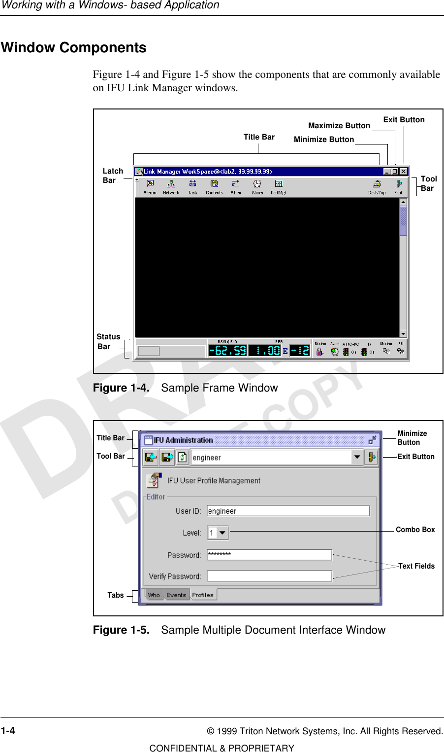
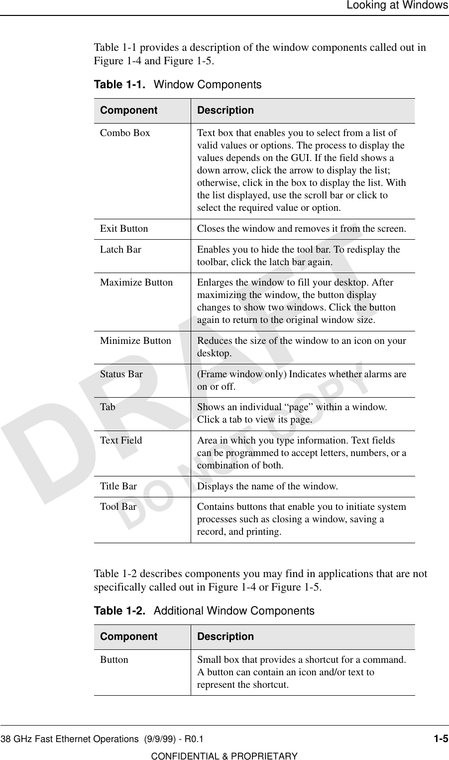
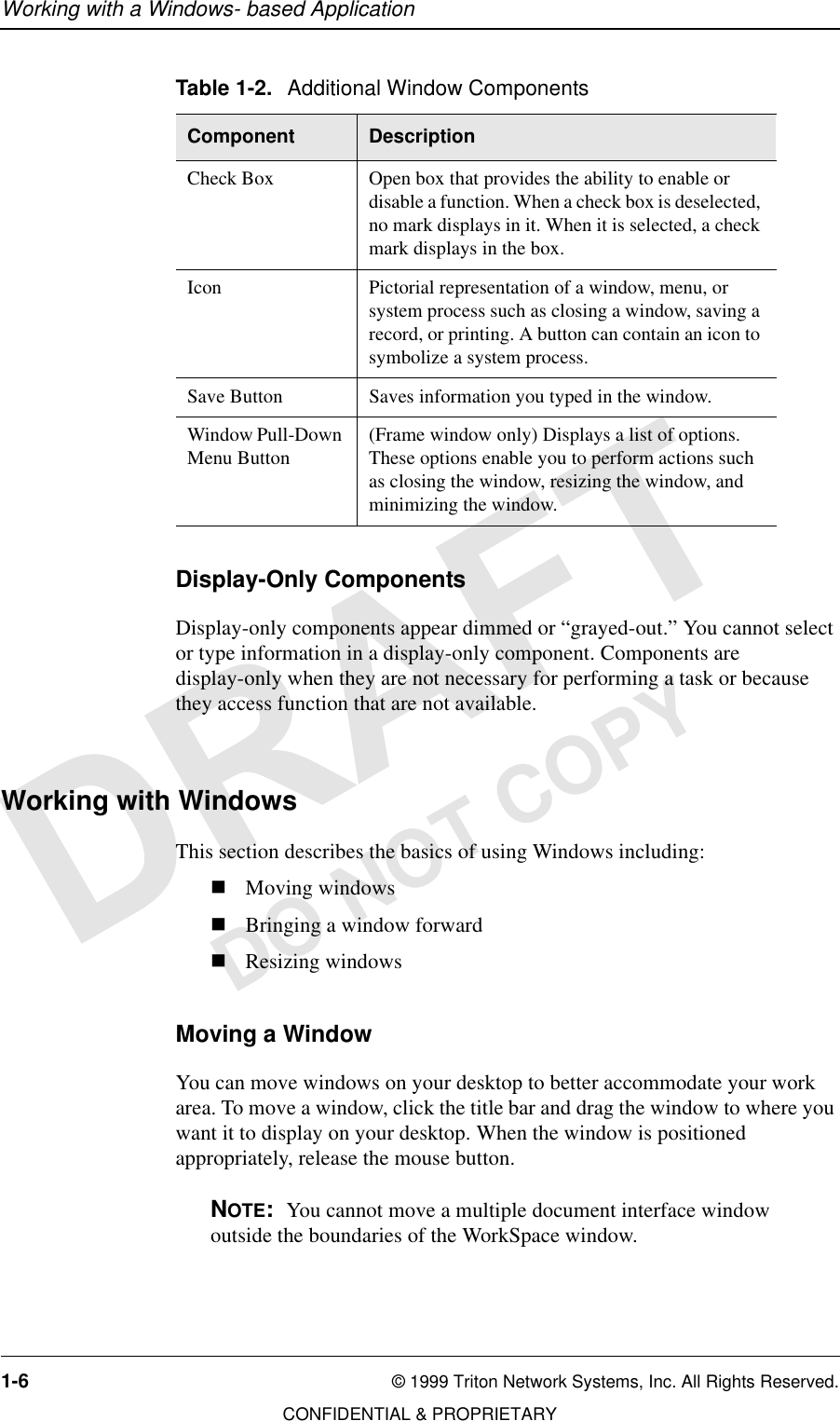
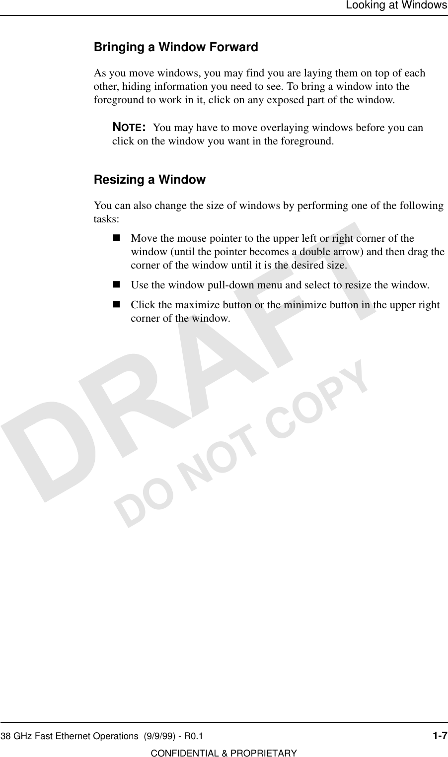
Operations Manual
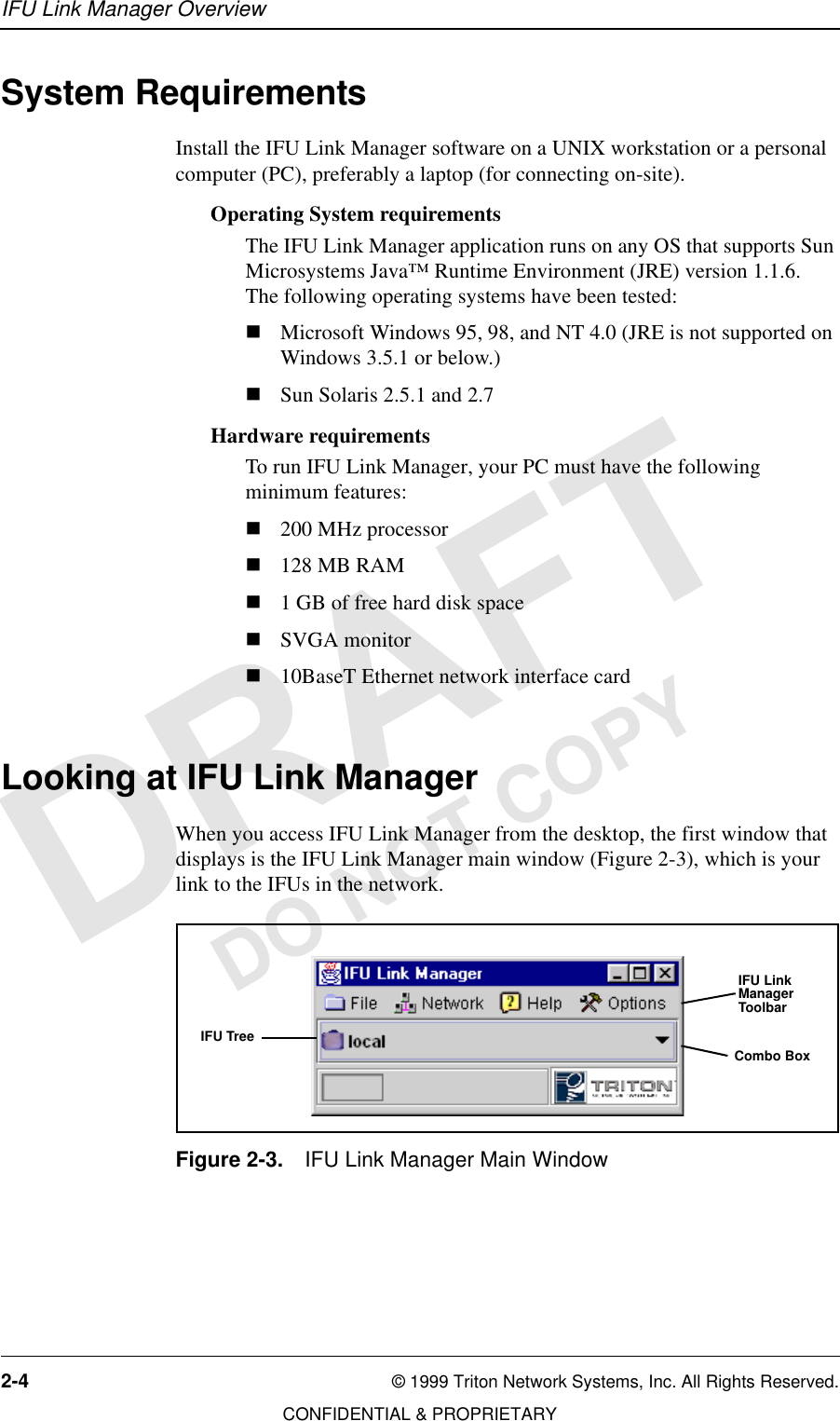
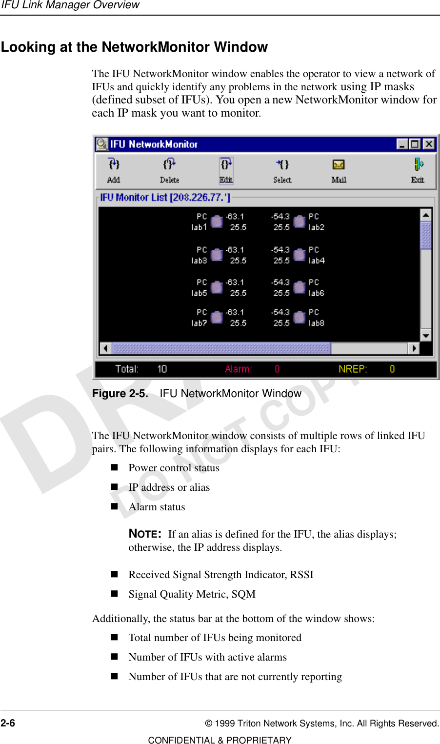
![DO NOT COPY,QYLVLEOH)LEHU708QLW2SHUDWLRQV0DQXDOIRU*+])DVW(WKHUQHW$SSOLFDWLRQV](https://usermanual.wiki/Triton-Network-Systems/28-ETP-FE.Operations-Manual/User-Guide-63134-Page-1.png)