Tyco Safety Canada 0010BASET ETHERNET HUB User Manual Installation Instructions
Digital Security Controls Ltd. ETHERNET HUB Installation Instructions
Installation Instructions
Four Channel 10BaseT Ethernet Hub Installation Instructions
Brian Wauchope
04/25/00
Specifications:
! Compliant with IEEE 802.3 specifications.
! Standby current draw = 96mA
! Maximum current draw = 330mA
! Input voltage range = 8 to 15VDC
! Maximum Bandwidth = 10MB/s
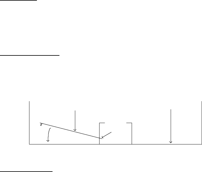
Mounting Instructions:
1. Locate a suitable mounting location for the Ethernet Hub module inside the cabinet.
2. Align the two mounting tabs with the holes located in the bottom of the wire raceway and insert.
3. Snap the module into place by pushing the opposite side towards the back of the cabinet.
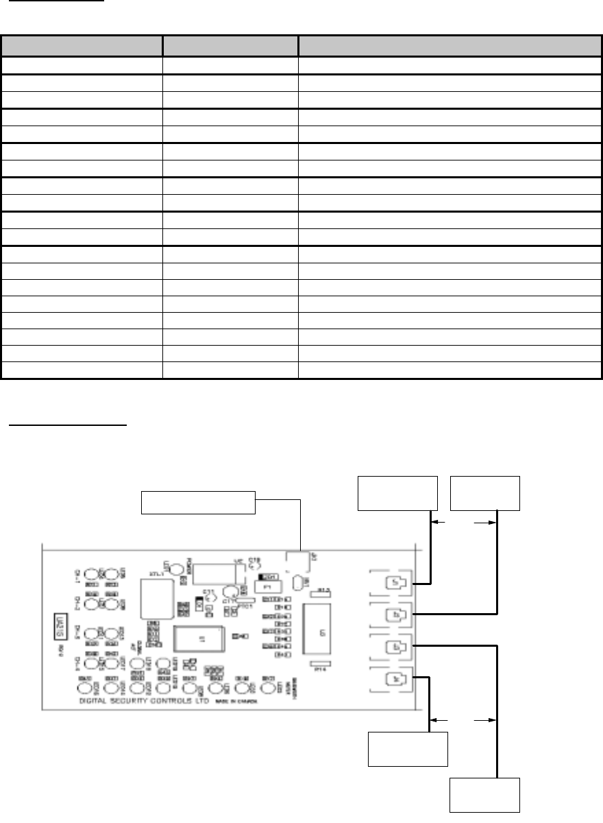
Wiring Instructions:
1. Home-run CAT-5 cable to each desired location throughout the dwelling and route into the cabinet.
2. Connect each CAT-5 drop to a port on the Ethernet Hub marked ‘Port 1’, ‘Port 2’, ‘Port 3’ or ‘Port 4’.
3. Locate a suitable 110VAC receptacle for placement of the wall-mount transformer.
4. Route the output cord from the wall-mount transformer (supplied) into the cabinet and plug into the
Ethernet Hub ‘PWR-IN’ jack.
5. Apply power to the wall-mount transformer.
Important: All requirements for Installation of CAT 5 should be met for proper operation of connected
equipment.
Some requirements of CAT-5:
Do not strip sheathing of cable more then required for proper termination. Do not kink or knot cable. Do
not crush cable with cable ties. Do not bend cable at right angles or sharp bends. All cable bends should
have a minimum of a 2" radius.
NOTE: A minimum of two and a maximum of four computers or peripherals must be connected for proper
operation of the hub. The network connections can be made on any available port on the hub and are not
restricted to certain ports. Also note that the computers and/or peripherals must be configured properly for
peak performance of the hub. Please consult the manual supplied with your operating system software.
CabinetModule
Tabs
LED Indication:
Label Color Function
Power Red Power presence
CH-1 Green Link Status
Yellow Collision Detect
CH-2 Green Link Status
Yellow Collision Detect
CH-3 Green Link Status
Yellow Collision Detect
CH-4 Green Link Status
Yellow Collision Detect
Global Act Red Collision
Yellow Carrier Sense
Bandwidth Meter Red >80% Bandwidth Utilization
Red >64% Bandwidth Utilization
Yellow >32% Bandwidth Utilization
Yellow >16% Bandwidth Utilization
Yellow >8% Bandwidth Utilization
Green >4% Bandwidth Utilization
Green >2% Bandwidth Utilization
Green >1% Bandwidth Utilization
Typical Installation:
Computer or
Networkable
Peripheral
Computer or
Networkable
Peripheral
CAT 5
Cable
Computer or
Networkable
Peripheral
Computer or
Networkable
Peripheral
CAT 5
Cable
9V DC 500mA Adapter