Tyco Safety Canada 05SKY Cellemetry Alarm Communicator User Manual 29034654 REV 001 SKYROUTE V2 4 IM EN
Digital Security Controls Ltd. Cellemetry Alarm Communicator 29034654 REV 001 SKYROUTE V2 4 IM EN
UserManual.wiki
>
Tyco Safety Canada
>
05SKY User Manual
Installation manual
Navigation menu
Upload a User Manual
Namespaces
Wiki Guide
HTML
PDF
Info
Views
User Manual
Discussion / Help
Navigation
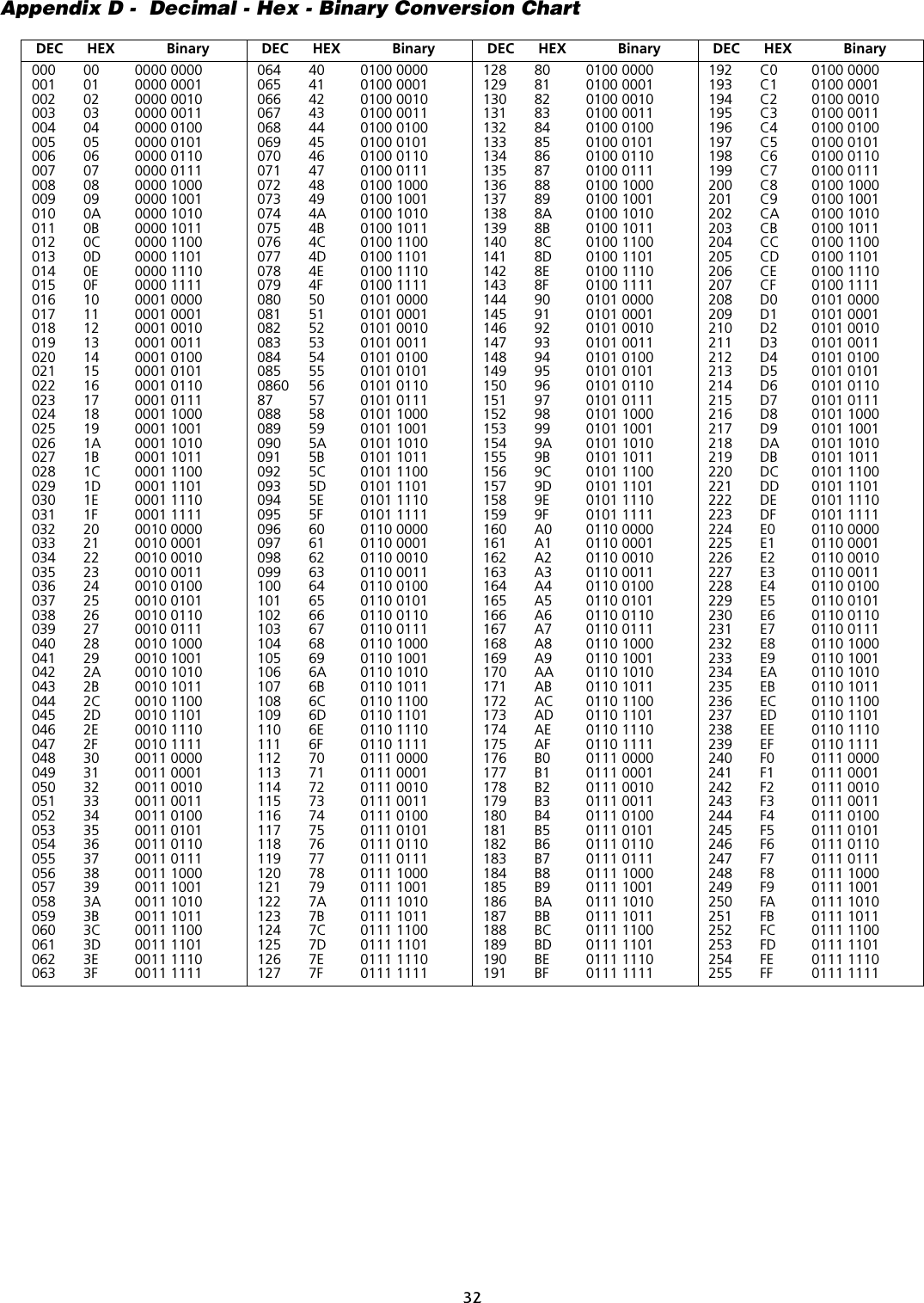
![Table of ContentsSKYROUTE QUICK INSTALL GUIDE 1Section 1 - Contents 21.1 Important Information .............................................................. 21.2 Skyroute Transceiver Glossary of Terms ................................ 2Section 2 - What is it? 22.1 Introducing the Skyroute Transceiver ...................................... 22.2 Specifications ........................................................................... 2Section 3 - How Does It Work? 33.1 Cellemetry Communication ..................................................... 33.2 Skyroute Reporting Methods ................................................... 3Section 4 - What Do I Do before Installing aSkyroute Transceiver? 5Section 5 - Installing a Skyroute Transceiver 65.1 Location of the Skyroute Unit ................................................. 65.2 Relocating the Skyroute Transceiver ....................................... 65.3 Relocating the Antenna ............................................................ 65.4 UL Requirements ..................................................................... 75.5 Installation ............................................................................... 85.6 Mounting the Skyroute Transceiver ........................................ 85.7 Mounting the Antenna .............................................................. 85.8 Keybus Connection .................................................................. 85.9 Bell IN Terminal ...................................................................... 85.10 Bell OUT Terminal .................................................................85.11 Tamper Terminal ....................................................................85.12 Secure Installation ..................................................................85.13 Connection Diagrams .............................................................85.14 Wiring Skyroute to a DSC/Partner Control Panel ................115.15 Supervised Power Supply Connection .................................11Section 6 - Programming and Activating a Skyroute 126.1 Defaulting ...............................................................................126.2 Programming Options ............................................................126.3 Activating a Skyroute Transceiver .........................................13Section 7 - [803] Skyroute Programming Worksheets 147.1 Defaulting ...............................................................................147.2 Basic Programming ................................................................147.3 Advanced Programming......................................................... 16Section 8 - Testing 25Section 9 - Troubleshooting 25Section 10 - For Your Records 26Appendix A: Reporting Codes 27Appendix B: Zone Alarms/Restorals 29Appendix C: Tamper Alarms /Restorals 31Appendix D: Decimal - Hex - Binary Conversion 32FCC COMPLIANCE STATEMENTCAUTION: Changes or modifications not expressly approved by Digital Security Controls Ltd. could void your authority to use this equipment.This equipment has been tested and found to comply with the limits for a Class B digital device, pursuant to Part 15 and Part 22 of the FCC Rules. These limits are designed to provide reasonableprotection against harmful interference in a residential installation. This equipment generates, uses and can radiate radio frequency energy and, if not installed and used in accordance with theinstructions, may cause harmful interference to radio communications. However, there is no guarantee that interference will not occur in a particular installation. If this equipment does causeharmful interference to radio or television reception, which can be determined by turning the equipment off and on, the user is encouraged to try to correct the interference by one or more of thefollowing measures:• Re-orient the receiving antenna.• Increase the separation between the equipment and receiver.• Connect the equipment into an outlet on a circuit different from that to which the receiver is connected.• Consult the dealer or an experienced radio/television technician for help.The user may find the following booklet prepared by the FCC useful: “How to Identify and Resolve Radio/Television Interference Problems”. This booklet is available from the U.S. GovernmentPrinting Office, Washington D.C. 20402, Stock # 004-000-00345-4.FCC ID: F5305SKYINDUSTRY CANADA COMPLIANCE STATEMENTThis Class B digital apparatus meets all requirements of the Canadian interference-causing equipment regulations.Cet appareil numérique de la Classe B respecte toutes les exigences de règlement sur le matériel brouilleur du Canada.IC: 160A-05SKYThe term “IC:” before the radio certification number only signifies that Industry Canada technical specifications were met.WARNING: To satisfy FCC RF exposure requirements for mobiletransmitting devices, a separation distance of 30 cm or moreshould be maintained between the antenna of this device andpersons during device operation. To ensure compliance, opera-tion at closer than this distance is not recommended.NOTE:The reference to "Skyroute" throughout this manual is applicable to the following model numbers: Skyroute and Skyroute (A).](https://usermanual.wiki/Tyco-Safety-Canada/05SKY/User-Guide-585886-Page-2.png)
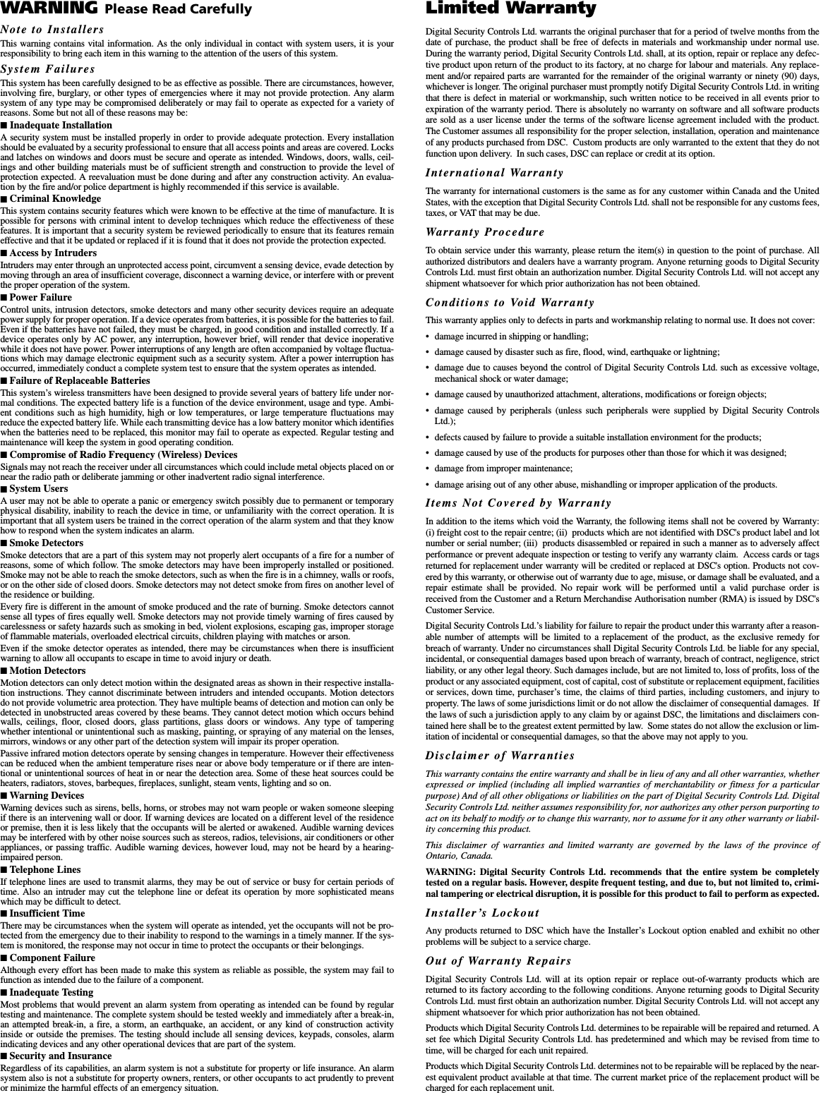
![1SKYROUTE QUICK INSTALL GUIDEIMPORTANT: You must be enrolled with CONNECT 24 to activate a Skyroute transceiver. If you are notalready enrolled, please call 1-888-955-5583 in Canada or 1-888-251-7458 in the U.S. at least 24 hoursprior to your first activation.STEP 1 – DETERMINE BEST SIGNAL LOCATION (See Section 5.1)Connect the Skyroute transceiver to a 7 Ah battery, as described in Section 5.1. Determine the best location for signal strength. If good signalstrength cannot be found, an antenna extension or relocation may be required.STEP 2 – CONNECT THE SKYROUTE TO THE PANEL (See Section 5.13)Mount and connect the Skyroute to the control panel as shown in Section 5.13.STEP 3 – PROGRAM THE SKYROUTE (See Section 6)Enter *8 + Installer Code to enter Programming Mode. Go to section [803], and program the following sections:DEFAULT THE SKYROUTE - Section [99]Select the Default option as described in Section 6.1 of this manual:• For FULL REPORTING……………….enter 00 into Section [99]• For FALLBACK REPORTING….….....enter 11 into Section [99]• For GENERIC REPORTING………..…enter 12 into Section [99]• For BACKUP REPORTING………..…enter 03 into Section [99]The Skyroute module will automatically restart, and default to the new setting.PROGRAM THE ZONE DEFINITIONS - Sections [01] through [04]• Program the Zone Definitions as described in Section 6.2.SELECT THE CELLULAR CHANNEL - Section [06]The Skyroute transceiver is defaulted for Channel B. If you require Channel A (see the SID List for the channel of the cellular service pro-vider in your area), perform the following:• In Section [06], TURN OFF OPTION 2, and TURN ON OPTION 1 (Press # to exit section [06])• In Section [10], enter the transmission time of day in 24-hour format (HHMM).NOTE: Due to the volume of wireless traffic generated by test signals, please select a time which is NOT on the :30 minute marks (i.e.,NOT 02:30, 04:00, etc. Select a time like 02:24, or 04:07, etc. wherever possible.• In Section [11], select the transmission day of the week.NOTE: This section is not to be used for UL Listed applications.• In Section [13], select Daily or Weekly testing as required.NOTE: Select this option in conjunction with the CONNECT 24 rate plan you are using for this installation. The default setting isweekly. For UL Listed applications daily test reports are required.STEP 4 – ACTIVATE THE SKYROUTE WITH CONNECT 24 (See Section 6.3)Call the Voice Response Unit (VRU) at the toll free number provided with your Dealer Confirmation.Once activated, send two signals to yourcentral station to confirm proper operation.YOUR SKYROUTE INSTALLATION IS NOW COMPLETE.ALL OTHER PROGRAMMING SECTIONS IN THIS MANUAL ARE OPTIONAL](https://usermanual.wiki/Tyco-Safety-Canada/05SKY/User-Guide-585886-Page-3.png)
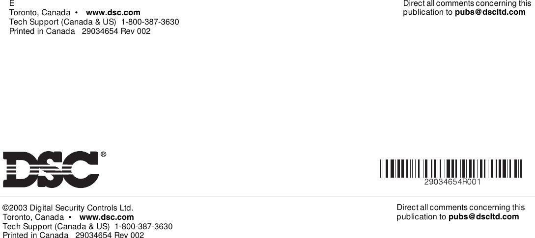
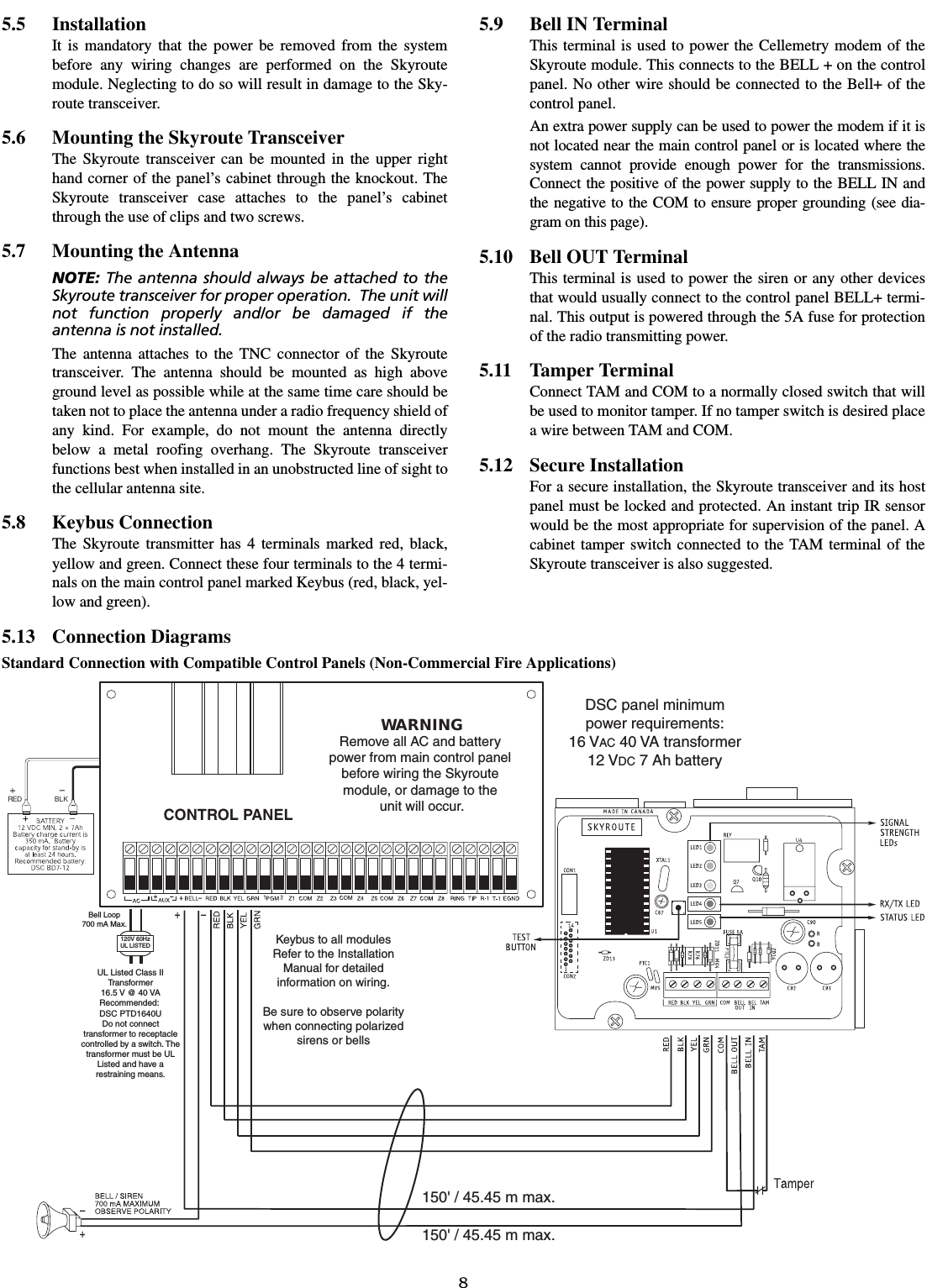
![3Section 3 - How Does It Work?3.1 Cellemetry CommunicationThe Skyroute transceiver communicates using the controlchannel of the existing cellular network. Signals are routed tothe Cellemetry Gateway via the SS7 cellular network. A clear-ing house then receives the signals and forwards the events tothe central station. Upon receiving an acknowledgement signalfrom the central station, the clearing house then returns a con-firmation of delivery signal to the Skyroute transceiver overthe network. For transmission sequence see drawing below:• The Skyroute transceiver reads the system activity directlyfrom the Keybus. It also sends the corresponding signalsover the cellular network, depending on what you have pro-grammed the Skyroute transceiver to send.• The Skyroute transceiver can be reprogrammed for full, backupor generic reporting (see Sections 6.1 and 7.1 ‘Defaulting’).• The Skyroute transceiver does not consider the signal to bereceived at the central station until it receives confirmationfrom the clearing house. Relay between signals can be up to60 seconds apart.NOTE: While the panel is in walk test mode, the Sky-route will still communicate all alarms.3.2 Skyroute Reporting MethodsReporting via Skyroute is in addition to landline communica-tions. Land line communications are unaffected by whichreporting method the Skyroute is using. A default of the Sky-route must be performed before activation (Enter 00, 11 or 22in sub-section [99] ‘Software Defaulting of the Skyroute’).This is necessary to configure the Skyroute for one of the fourpossible reporting methods:1: ‘Full Reporting’ (Enter 00 in sub-section [99]) 2: ‘Generic Reporting’ (Enter 12 in sub-section [99])3: ‘Generic Reporting with fallback to Full Reporting’ (Enter11 in sub-section [99])4: ‘Backup Reporting’ (Enter 03 in sub-section [99]) Other important things to note:• For an event to report via the Skyroute, the event reportingcode in sections [30]-[78] must be programmed as [FF] andthe associated ‘Transmission Option’ (in section [22]) mustbe enabled.• To disable a specific event from reporting via the Skyroute,program the reporting code as [00]. • To disable a group of reporting codes from reporting via theSkyroute, turn OFF the respective ‘Transmisison Option’ insection [22].• The Skyroute does not follow the ‘Event Buffer FollowsSwinger Shutdown’ option in the control panel.3.2.1 Full Reporting(Enter 00 in sub-section [99])All events in sections [30]-[78] are automatically programmedas [FF] and will be sent by the Skyroute. To disable a specificevent from sending via the Skyroute, program the reportingcode as [00]. To disable a group of reporting codes from send-ing via the Skyroute, Turn OFF the respective ‘TransmisisonOption’ in section [22]. When using ‘Full Reporting’ it is very important to understandthat when multiple signals need to be sent, there is approxi-mately a one-minute delay between each signal sent via theSkyroute. Because of this delay, the Skyroute will buffer sig-nals when multiple events occur and transmit them in the orderreceived. For example; if you need to send 4 signals (i.e. alarm zone 1,alarm restore zone 1, alarm zone 2, alarm restore zone 2), itwill take approximately 4 minutes for the Skyroute to send all4 signals. The first signal sends immediately, then the remain-ing three signals are each sent approximately 1 minute apart inthe order that they occurred.When using Full Reporting, the central station will receive thesame signal from the panel via landline communications andfrom the panel via Skyroute Communications. This is why it isimportant to contact your central station regarding dual signalcommunication. The automation system at the central stationmust be able to suppress redundant signals.3.2.2 Generic Reporting (Enter 12 sub-section [99])Generic Reporting is used to avoid duplicate alarm signals frombeing received at the central station. It also avoids the largedelays between landline signals and Skyroute signals that occurwhen multiple events of the same type happen within a shorttime period (both of which occur when using ‘Full Reporting’). Generic reporting only applies to certain types of alarm events.These events are grouped together into one of 4 categories.Each category has a specific alarm reporting code. When oneof these alarms occur, the Skyroute will send the associatedalarm reporting code for the category the alarm belongs to –and then start a timer for that category (5 minutes at defaultprogrammed in section [21]). If another alarm occurs in thesame category while its timer is active, then no signal is gener-ated via the Skyroute for that category. If an alarm occurs in adifferent category, then the Skyroute will send the associatedalarm reporting code for that category – and then start a timerfor that category (5 minutes at default – programmed in section[21]). Each category has it’s own timer. If a new alarm eventoccurs after the timer has expired for its category, the sequence](https://usermanual.wiki/Tyco-Safety-Canada/05SKY/User-Guide-585886-Page-5.png)
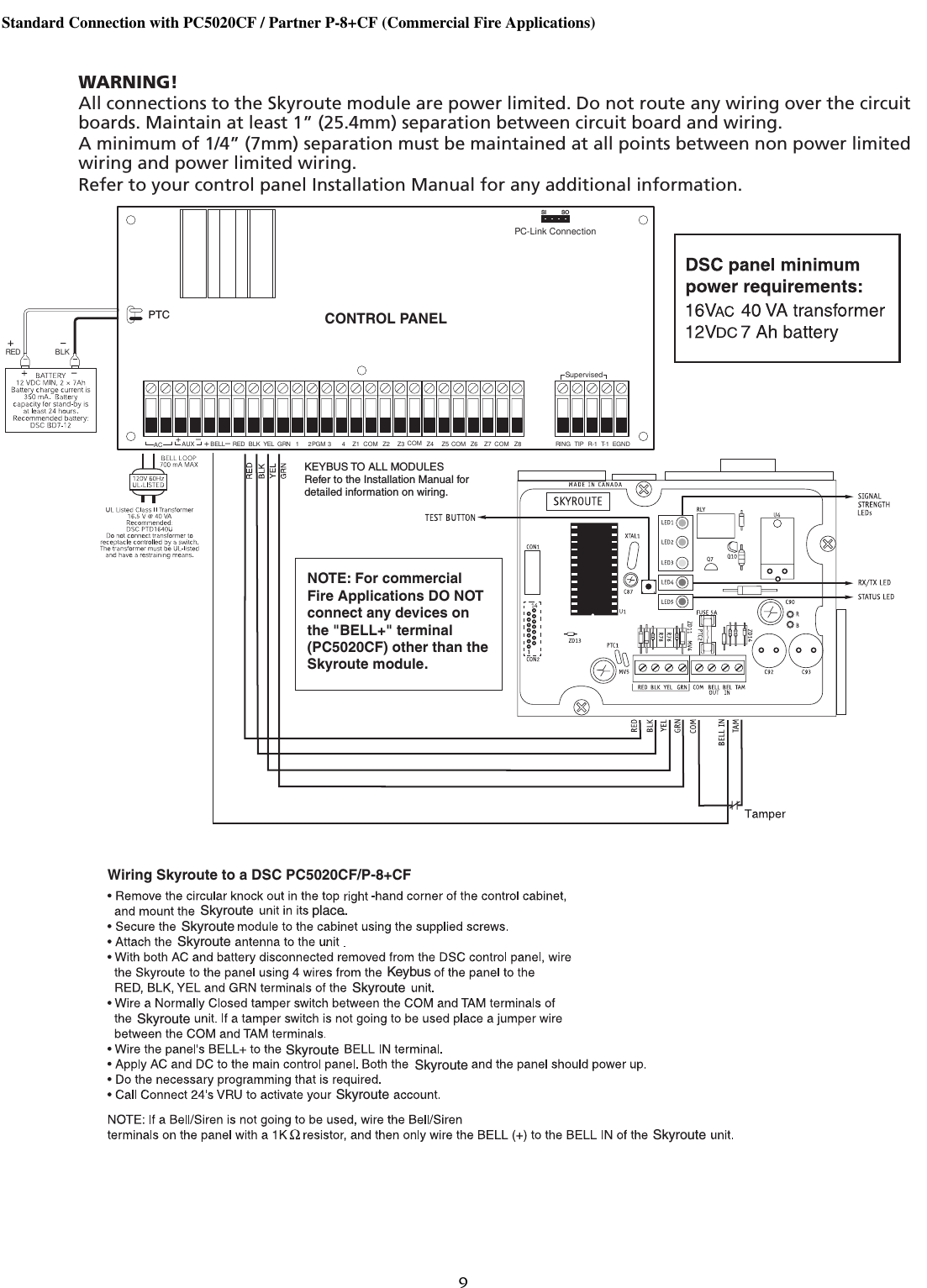
![4restarts. All events that are not included in one of the 4 catego-ries (noted below) will be fully transmitted by the Skyroute (ifthe associated reporting codes are programmed and ‘Transmis-sion Options’ are ON). While in Generic Mode, the panel will group the followingalarm events together as follows:• Burglary: Delay 1, Delay 2, Instant, Interior, Interior Stay/Away, Delay Stay/Away, 24 Hour Burglary, 24 Hour Latch-ing Tamper, Momentary Keyswitch Arm, Maintained Key-switch Arm, Links Answer• Fire: Delayed Fire, Standard Fire, Delayed Fire (wireless),Standard Fire (wireless), 2-Wire Smoke (PGM2), KeypadFire.• Supervisory: 24 Hour Supervisory Buzzer, Silent 24 Hr(PGM2), Audible 24 Hr (PGM2), Zone Expander Supervi-sory Alarm.• Panic: 24 Hour Panic, Keypad PanicGeneric Signals3.2.3 Generic Reporting with Fallback to Full Reporting (Enter 11 in sub-section [99])Normally, the Skyroute will use ‘Generic Reporting’ (describedearlier). At any time if the Skyroute receives either a FTC (Fail-ure to Communicate) or a TLM (Telephone Line Monitor) trou-ble from the main panel via the Keybus, the Skyroute willswitch into ‘Full Reporting’ and send alarm signals as outlinedabove in ‘Temporary Full Reporting’ (Note: When using‘Generic Reporting with Fallback to Full Reporting’ and theSkyroute switches to ‘Full Reporting’ upon receiving and ‘FTC’or ‘TLM’ from the panel, the Skyroute will transmit the alarmsignals with the specific zone numbers without restorals).When the Skyroute switches into ‘Full Reporting’, the FTC orTLM trouble will be the first signal sent by the Skyroute. Forthe Skyroute to switch back into ‘Generic Reporting’, the TLMor FTC trouble must restore and a signal must be received bythe Skyroute from the main panel via the Keybus. Upon restoral of the TLM or FTC Trouble, any signals thatoccurred before the TLM or FTC trouble restored that stillneed to be transmitted will be sent via the Skyroute until theSkyroute’s communications buffer is empty. In addition, if newalarms occur after switching back to ‘Generic Reporting’ whilefull reporting events are still in the Skyroute’s communicationbuffer, the Skyroute will generate the generic signal, place it atthe end of the communication buffer and function as outlinedabove for ‘Generic Reporting’.3.2.4 Backup ReportingIn Backup Reporting mode the Skyroute will only transmitevents when the panel is unable to transmit them. It must beunderstood that the potential exists that in some situationsevents may be duplicated on the landline, however when theSkyroute is in backup mode it will attempt to not send eventsthat can be successfully transmitted over the phone line by thepanel.Internally in the Skyroute, events are buffered with a times-tamp. The timestamp is in intervals of 10 seconds yielding amaximum time of approximately 42 minutes. The BackupTimer Section[19] will control how long events will remain inthe buffer before they expire. If an event in the buffer expires(ie. the timestamp on the event in the buffer is older than thecurrent timestamp) it will be deleted from the buffer. If an FTCevent is received from the Keybus, all events that have notexpired in the buffer will be transmitted, and the Skyroute willtemporarily go into full reporting mode. The Skyroute willremain in full reporting mode until an FTC Restore event isretrieved from the buffer. FTC and FTC Restore will also betransmitted. The Skyroute will then return to Backup mode.TLM Trouble and TLM Trouble restore events will always betransmitted, and any events that are generated by the panel inbetween these events will also always be transmitted.It is important to program the Backup Timer Section [19] to aValue that correlates to the amount of time it will take for thepanel to FTC. If the panel takes longer to FTC than is pro-grammed in Section [19], then events may expire and no trans-mission by the Skyroute will occur. If the panel takes less timeto FTC than is programmed into Section [19] then duplicateevents may occur. It is suggested to reduce the panel's numberof dialing attempts to 5 (refer to the Panel's programming), inorder to reduce the time it takes before the Skyroute willswitch into Full Reporting. The following table can be used tohelp determine what value should be used in Section [19].NOTE: This table refers to panel programming, withthe default values for dialing the receiver. If program-ming has been done in the panel (for example, Post-Dial Wait for Handshake or Delay Between DialingAttempts), then the values used in the Skyroute mustreflect these changes by adding the difference in pro-grammed time to section [19] of the Skyroute.If the panel is programmed for two phone numbers, then Sec-tion [19] should be doubled from what is shown.The types of events that trigger the Skyroute to temporarilyswitch into full reporting mode can be configured in theBackup FTC options, in Section [18]. NOTE: Do not use backup mode for Commercial Fireor Commercial Burglary installations. Use only in ULResidential Fire or Burglary installations.SIA Contact IDBurglary Partition x Event BA zone 98Partition x Event 130 zone 098Fire Partition x Event FA zone 98Partition x Event 110zone 098Supervisory Partition x Event US zone 98Partition x Event 140zone 098Panic Partition x Event PA zone 98Partition x Event 120zone 098Panel's Max Dialing AttemptsTotal PanelTimeValue to Program into Section [19]1 90 seconds 09 (9 decimal)5 450 seconds 2D (45 decimal)8 720 seconds 48 (72 decimal)](https://usermanual.wiki/Tyco-Safety-Canada/05SKY/User-Guide-585886-Page-6.png)
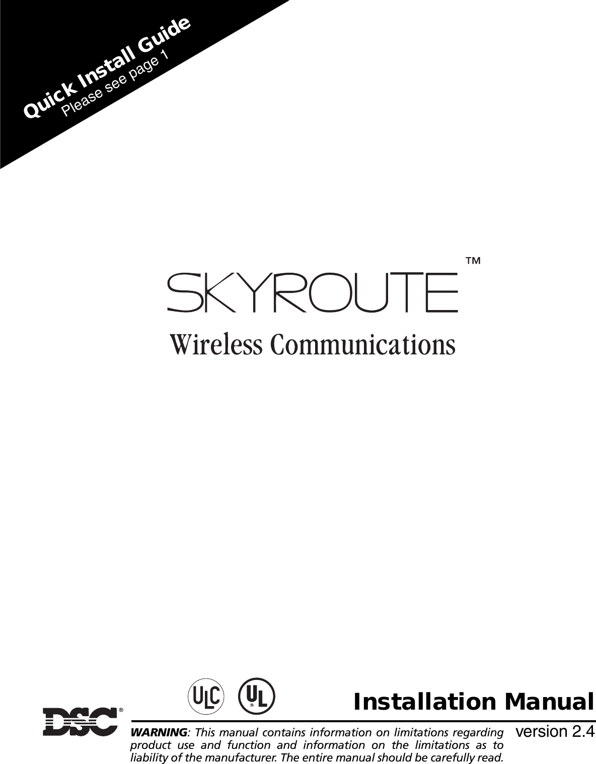
![6Section 5 - Installing a Skyroute TransceiverTime-Saving Tips: By powering up the Skyroute transceiver on a battery alone (battery red to Bell In and Keybus red, battery black toKeybus black), you can quickly determine a location where your signal strength is strong prior to installing the unit. The Skyroute unitdoes not have to be active to show signal strength.5.1 Location of the Skyroute UnitIt is very important to determine the best location for maximum signal strength.Verify signal strength prior to installation!1: Normal (activated) The radio is operating normally andthere are no troubles with the Skyroute.2: Radio not Responding Possible causes; the radio in theSkyroute is not powered up, the initialization of cellemetryradio has failed, an internal problem with the radio, bad dataconnections between the radio and the panel.3: Failed self-test A self-test of the cellemetry module has failed.4: No cell network The cellemetry modem has failed to regis-ter with the cellular network (Ie. no network coverage orvery weak signal).5: Failure to communicate The Skyroute has not successfullycommunicated a signal to the central station (the Skyroutehas not received the acknowledgement that the central sta-tion successfully received a signal).6: Ready to Activate The Skyrotue has not been activatedwith Connect 24.8: Keybus Fault The Skyroute cannot communicate to the panel.NOTE: If there is a Skyroute trouble, the panel it isconnected to will display a ‘General System Supervi-sory’ trouble.NOTE: If the [TAM] to [COM] terminals are open onthe Skyroute, the panel it is connected to will displaya ‘General System Tamper’ trouble.5.2 Relocating the Skyroute TransceiverSince the Skyroute transceiver is a Keybus accessory, it is pos-sible to relocate the module up to 150 feet (45.4 m) from themain control panel when the panel is not located in a good Cel-lemetry coverage area (a control panel installed in a vault forexample). When relocating the module, follow theses rules:• Maximum of 150 feet (45.4 m) from the main control. Key-bus (Red, Black, Yellow, Green) from the panel to the Sky-route transceiver.• A UL1481 Listed power supply 12V@1.5A must be used forUL installations.• The power supply (+ positive) is connected to the Skyroutetransceiver (BELL IN) terminal and the power supply (–negative) to the Skyroute transceiver (COM) terminal.• The cabinet must be installed in a secure location and shouldhave a tamper circuit connected to the Skyroute (TAM andCOM) terminals.5.3 Relocating the AntennaIf a suitable location is not available for proper Cellemetry cov-erage, obtain an Antenna Extension Bracket Kit from your DSCsupplier. Each kit contains an extension cable, a mountingbracket, instructions, and all required hardware. Three lengths ofextension cable are available:Only use the Extension Kits to extend the mounting rangeof the antenna. Do not cut or splice the extension cable. Themaximum distance between the Skyroute transceiver and theantenna is 25 feet (7.62 m) as obtained by using the LAE-25 orSKR-025 Extension Kit. Make sure the antenna is in a physi-cally secured location to avoid tampering.Secure the TNC connector from the Extension Kit to themounting bracket, ensuring that the star washers make solidelectrical contact with the mounting bracket.Remove the antenna from the Skyroute module and connect theextension cable to the TNC connector on the module. Secure theantenna to the TNC connector mounted on the Extension Kitmounting bracket. Locate the mounting bracket and antenna awayfrom possible sources of electrical interference. Moving theantenna just a short distance will likely be adequate. Temporarilysecure the mounting bracket in the new location and proceed withtesting. If the test is successful, permanently secure the mountingbracket and antenna at the new location.Extension Kit Length of cableLAE-3 3 feet (0.91 m)LAE-15 15 feet (4.57 m)LAE-25 25 feet (7.62 m)SKR-025 25 feet (7.62m)](https://usermanual.wiki/Tyco-Safety-Canada/05SKY/User-Guide-585886-Page-8.png)
![7Antenna Relocation Diagram5.4 UL Requirements5.4.1 Grade A - Central Station Service, Residential Fire and Burglary Installations• Programming [13] - Option 2 Test Rates must be “ON”.• Every 24 hours a check-in signal must be sent to the centralstation. Refer to compatible Listed control unit’s installationinstructions for programming.• Dialing attempts must be programmed for 5 to 10 attempts.Skyroute transmitter makes 3 attempts by default. Refer tocompatible Listed control unit’s installation instructions forprogramming.• The response wait time, section [24] should be set to 09.• Alarm signals must be sent over both primary and secondarycommunication paths -1. Compatible Listed control unit’s land line to central sta-tion (primary).2. Skyroute transmission through Cellemetry to the clearinghouse (Connect 24) (secondary).• DACT must be enabled for Listed compatible control unit.5.4.2 Police Station Connect with Basic Line Security• Same as Grade A Central Station Installations.5.4.3 Commercial Fire Installations• Same as Grade A Central Station Installations.• The BELL+ and BELL- terminals on the control panel shallnot power other devices. Refer to Compatible Listed controlunit installation instructions for wiring and programming.5.4.4 Back-up Reporting Mode (03) • To be used only for UL/ULC residential Fire and Burglaryapplications.5.4.5 For ULC Installations• The redundant Communication mode (00) meets level 2 linesecurity requirements.Antenna Extension KitsLAE-3 3-ft. (0.9m) extension kitLAE-15LAE-25SKR-02515-ft. (4.6m) extension kit25-ft. (7.6m) extension kit25-ft. (7.6m) extension kit (external)](https://usermanual.wiki/Tyco-Safety-Canada/05SKY/User-Guide-585886-Page-9.png)
![12Section 6 - Programming and Activating a Skyroute6.1 DefaultingNOTE: This product must be defaulted BEFORE pro-gramming/activating.Select the type of default as follows:6.1.1 Full Reporting• Entering 00 in sub-section [99]1. A complete default of the system is performed2. All reporting sub-sections, [30] through [78] are automat-ically programmed as [FF] and will be sent by the Sky-route transceiver.6.1.2 Generic Reporting with Fallback to Full Reporting• Entering 11 in sub-section [99]* 1. A complete default is performed.2. Reduced Reporting as follows:Reduced Reporting1. Alarm Restoral Reporting Code, sub-sections [34]through [38], will be automatically programmed to [00],except the duress alarm.2. The Keypad and PGM Restorals in section [39] will beprogrammed to [00]. Zone Tamper & Restoral reportingcode, sub-sections [40] through [48], will be programmedto [00]**.3. Zone Supervisory & Restoral, sub-sections [49] through[56], will be programmed to [00]**.4. Zone Low Battery Alarm & Restoral, sub-sections [57]through [64], will be programmed to [00]***.5. Keypad Zone Restoral, sub-section [39], last 4 program-ming locations, will be programmed as [00].6. Miscellaneous Restoral and Periodic Test in sections [77]and [78] will be programmed as [00].In Generic mode, see Appendix A for Generic signals. (SeeSection 3 ‘How Does It Work?’ for description of each report-ing method). 6.1.3 Generic Reporting• Entering 12 in sub-section [99]*1. A complete default is performed2. Reduced Reporting as indicated above.In Generic mode, see Appendix A for Generic signals. (SeeSection 3 ‘How Does It Work?’ for description of each report-ing method.) 6.1.4 Backup Reporting• Entering 03 in sub-section [99]1. A complete default is performed.2. All reporting sub-sections [30] to [78] are automatically pro-grammed as [FF] and will be sent by the Skyroute Transceiver.• Entering 13 in sub-section [99].1. A complete default is performed.2. The Skyroute will be programmed for backup mode.6.2 Programming OptionsAll programming on the Skyroute transceiver is done in theInstaller Programming mode. Refer to the control panel’sInstallation Manual for instructions on how to enter InstallerProgramming. From Installer Programming, enter section[803] to go to the Skyroute programming sections. Sub-sections [01] to [22] apply to all other installations. 6.2.1 Basic Programming Zone Definition: Sub-sections [01] to [05]These sections must be programmed exactly the same as themain control panel. This allows the Skyroute transceiver totranslate information sent along the Keybus and identify theproper event. NOTE: The Skyroute module will not follow any zonetransmission delays; i.e., any zones programmed witha delay will be sent immediately by the Skyroutetransceiver.Configuration Options: Sub-section [06]• Channel A enable/disable…………..option [1]This option must be selected when the Cellemetry provideris an “A” side carrier. • Channel B enable/disable…………..option[2]This option must be selected when the Cellemetry provideris a “B” side carrier.• Home system only enable/disable…option[3]This option must be programmed to ensure that the Skyroutetransceiver is communicating using the proper carrier. Whenselected, the transceiver will only use towers with the sameSID (as programmed in section [07]). NOTE: For US locations please refer to ‘U.S.A. SID List -By State’. For Canadian locations please select channel B.• To activate the Skyroute module in Home mode:1. Select a channel, A or B, in address 06 (Option 1 or 2)2. Wait for signal strength.3. Enter in address 07 the Home SID number in hexadecimalformat.4. Select Home mode (Option 3) and deactivate A or B chan-nel in address 06.NOTE: After changing sub-section [06] or [07] arestart is required. Enter [*FF] in section [99].Skyroute transceiver SID (System ID): Sub-section [07]Please refer to the SID table included with the Skyroute mod-ule to determine the SID number for your area.Skyroute Test Time: Sub-section [10]In this section enter the time of the day (24-hour format) youwant the test transmission to be sent.Test Transmission Day Mask: Section [11]In this section select the day of the week on which you wantthe test transmission to be sent. NOTE: This option cannot be used for UL Listed instal-lations.* Any reporting code sub-section not mentioned is pro-grammed as [FF].** These signals only apply to installations with double EOL.*** These signals only apply to installations with wireless zonemodules.](https://usermanual.wiki/Tyco-Safety-Canada/05SKY/User-Guide-585886-Page-14.png)
![13Skyroute Test Rates: Sub-section [13]• Option 1- Not used.• Option 2- Daily Test: If this option is ON, the Skyroute willself-generate a ‘Skyroute Test Transmission’ signal (TX-00or E603-000) every day.• Option 3- Weekly Test: If this option is ON, the Skyroutewill self-generate a ‘Skyroute Test Transmission’ signal(TX-00 or E603-000) every week.• Option 4 – Keybus Tests Enabled: If this option is ON, theSkyroute will send a ‘Periodic Test Transmission’ signal(RP-00 or E602-000) at the same time the main panel sendsits ‘Periodic Test Transmission’ via the land line.Backup FTC Options: Sub-section [18]All FTC or Trouble conditions must be restored for the Sky-route to return to backup mode. All trouble conditions thatcaused the Skyroute to switch to Temporary Full ReportingMode must be restored before it returns to Backup Mode.Backup Mode Timer: Sub-section [19]This option should correlate with the timing set in the panel.Refer to Panel Programming documentation and 3.2.4.Generic Signal Timer: Sub-section [21]This is the timer used by Generic Reporting. See Section 3 formore information.Transmission Options: Sub-section [22]This section will enable sections of reporting codes. (See tablefor different service plans.)Refer to Appendices Aand B to find out which reporting codesare controlled by each transmission option.6.2.2 Advanced ProgrammingIndividual Event: Sub-sections [30] to [78]These sections are used to determine if an event will be trans-mitted by the Skyroute transceiver. If ’00’ is entered, that eventwill not be transmitted. If ‘FF’ is programmed, the event willbe transmitted. ‘FF’ is the default value.The Skyroute module will send these events when they occurin the system unless they are programmed as ‘00’. Refer toAppendices A and B for more information.6.3 Activating a Skyroute TransceiverBefore activating the Skyroute transceiver, ensure that the con-trol panel is wired, programmed and operating properly. Makesure that the Skyroute transmitter is properly connected to theKeybus and to the bell (+ positive) circuit. When power isapplied to the system, the Skyroute transceiver will performself-diagnostics for a few seconds, before giving visual feed-back by indicating signal strength on LED1, LED2 or LED3.6.3.1 Calling Connect 24Once the Skyroute transceiver is indicating the signal strengthof the network, and the status indicator (LED5) is blinking 6times (not connected to the clearing house), you are ready tocall Connect 24’s Voice Response Unit. Follow the voiceprompt and when asked to perform a test, press SW1 on theSkyroute transceiver to transmit a test signal. When transmit-ting, LED4 blinks once. If the test is successful, the VRU willgive you a confirmation and LED5 will then blink steady everysecond. Refer to the Connect 24 information package for moreinformation on the activation process. NOTE: The confirmation of a successful test from Con-nect 24 does not guarantee proper transmission ofthe event to your central station. You must performnormal tests with your central station after activationwith Connect 24.6.3.2 Transmitting and ReceivingLED4 on the Skyroute module will blink once (1) to indicatethe cellular tower has received the signal. It will blink twice(2) to indicate the alarm central station has received andacknowledged the signal.6.3.3 Skyroute Transceiver Trouble SupervisionThe Skyroute transceiver automatically monitors its operationand indicates trouble conditions by flashing LED5 on the cir-cuit board. LED5 normally flashes once every 2 seconds whenthe Skyroute transceiver is on standby (ready to transmit)mode. Troubles are indicated when LED5 flashes more thanonce every 2 seconds. See Section 5.1 ‘Location of the Sky-route Unit’ for the number of flashes used to indicate eachtrouble condition in order of importance.1E I___I___I (hex) (number x 10 seconds)Generic ReportingFull Reporting OptionON ON I___I 1Alarms/Restoral DisabledOFF ON I___I 2 Tamper Resto-ral/RestoralDisabledOFF ON I___I 3 Supervisory/RestoralDisabledOFF ON I___I 4 Low Battery/Restoral DisabledOFF OFF I___I 5 Opening/ClosingDisabledON ON I___I 6 Maintenance/RestoralDisabledOFF OFF I___I 7 & 8 Not Used](https://usermanual.wiki/Tyco-Safety-Canada/05SKY/User-Guide-585886-Page-15.png)
![14Section 7 - [803] Skyroute Programming Worksheets (PC5020/PC5010/PC580/1PC555/PC5015/P-832/P-48/P-6B/P-832DL)7.1 DefaultingA default must be performed before activating the Skyroute transceiver. For UL Listed installations, refer to the compatible controlpanel Installation Manual for programming the number of panel attempts. The number of attempts between the Skyroute and thepanel must be between 5 to 10 attempts. The Skyroute transceiver’s default is 3 attempts.[99] Section [99] is for software defaulting of the Skyroute module• Entering 00 will cause a software default of the Skyroutemodule to Full Reporting. • Entering 11 will cause a software default of the Skyroutemodule and Generic reporting with fall-back to Full report-ing if TLM or FTC trouble occurs.• Entering 12 will cause a software default of the Skyroutemodule and Generic reporting. • Entering FF will cause restart of the Skyroute transceiver. • Entering 03 will cause a software default of the Skyroutemodule and Backup Reporting.7.2 Basic ProgrammingZone Definitions[01] Zone 1-16 Definitions[02] Zone 17-32 Definitions[03] Zone 33-48 Definitions[04] Zone 49-64 DefinitionsI___I___I00 Null Zone (Not Used) 12 24 Hour Holdup* 23 Maintained Keyswitch Arm*01 Delay 1* 13 24 Hour Gas* 24 LINKS1000 Answer*02 Delay 2* 14 24 Hour Heating* 25 Interior Delay*03 Instant* 15 24 Hour Auxiliary* 26 24 Hour Non-alarm*04 Interior* 16 24 Hour Panic* 27 Delayed 24 Hour Waterflow05 Interior, Stay/Away* 17 24 Hour Emergency* 28 Instant 24 Hour Waterflow06 Delay, Stay/Away* 18 24 Hour Sprinkler* 29 Auto Verified Fire07 Delayed 24 Hour Fire (Hardwired)** 19 24 Hour Water* 30 Fire Supervisory08 Standard 24 Hour Fire (Hardwired) 20 24 Hour Freeze* 31 Day Zone*09 24 Hour Supervisory 21 24 Hour Latching Tamper* 87 Delay 24 Hour Fire (Wireless)**10 24 Hour Supervisory Buzzer* 22 Momentary Keyswitch Arm* 88 Standard 24 Hour Fire (Wireless)**11 24 Hour Burglary**For burglary applications only** For residential fire applications onlyDefault Default Default Default00 I___I___I Zone 1 00 I___I___I Zone 5 00 I___I___I Zone 9 00 I___I___I Zone 1300 I___I___I Zone 2 00 I___I___I Zone 6 00 I___I___I Zone 10 00 I___I___I Zone 1400 I___I___I Zone 3 00 I___I___I Zone 7 00 I___I___I Zone 11 00 I___I___I Zone 1500 I___I___I Zone 4 00 I___I___I Zone 8 00 I___I___I Zone 12 00 I___I___I Zone 16Default Default Default Default00 I___I___I Zone 17 00 I___I___I Zone 21 00 I___I___I Zone 25 00 I___I___I Zone 2900 I___I___I Zone 18 00 I___I___I Zone 22 00 I___I___I Zone 26 00 I___I___I Zone 3000 I___I___I Zone 19 00 I___I___I Zone 23 00 I___I___I Zone 27 00 I___I___I Zone 3100 I___I___I Zone 20 00 I___I___I Zone 24 00 I___I___I Zone 28 00 I___I___I Zone 32Default Default Default Default00 I___I___I Zone 33 00 I___I___I Zone 37 00 I___I___I Zone 41 00 I___I___I Zone 4500 I___I___I Zone 34 00 I___I___I Zone 38 00 I___I___I Zone 42 00 I___I___I Zone 4600 I___I___I Zone 35 00 I___I___I Zone 39 00 I___I___I Zone 43 00 I___I___I Zone 4700 I___I___I Zone 36 00 I___I___I Zone 40 00 I___I___I Zone 44 00 I___I___I Zone 48Default Default Default Default00 I___I___I Zone 49 00 I___I___I Zone 53 00 I___I___I Zone 57 00 I___I___I Zone 6100 I___I___I Zone 50 00 I___I___I Zone 54 00 I___I___I Zone 58 00 I___I___I Zone 6200 I___I___I Zone 51 00 I___I___I Zone 55 00 I___I___I Zone 59 00 I___I___I Zone 6300 I___I___I Zone 52 00 I___I___I Zone 56 00 I___I___I Zone 60 00 I___I___I Zone 64](https://usermanual.wiki/Tyco-Safety-Canada/05SKY/User-Guide-585886-Page-16.png)
![15[05] PGM2 Definition[06] Skyroute Configuration Options[07] Home SID Number[10] Skyroute Test Time[11] Test Transmission Day Mask - This section is not to be used for UL Listed applications.[13] Skyroute Test Rates[18] Backup FTC Options[19] Backup Reporting Mode Timer[20] Communication ModeThis section will display the mode in which the Skyroute operates. To change the mode refer to section [99].•00 - Skyroute module is in Full Reporting Mode •11 - Skyroute module is in Generic Reporting with fall-backto Full Reporting if TLM or FTC trouble occurs•12 - Skyroute module is in Generic Reporting Mode•03 - Skyroute module is in Backup Reporting Mode00 I___I___I 04 = 2 Wire Smoke, 23 = silent 24 Hour Input, 24 = Audible 24 Hour Input.Default Option ON Option OFFOFF I___I Option 1 ‘A’ Channel Selected ‘A’ Channel Not SelectedON I___I Option 2 ‘B’ Channel Selected ‘B’ Channel Not SelectedOFF I___I Option 3 Home System Only Not in Home System OperationOFF I___I Option 4 Unit Active with Connect 24 Unit Not Active with Connect 24OFF I___I Options 5 to 8 System Use - DO NOT CHANGE0000 I___I___I___I___I This is the SID (in Hex) of the cellular service that is available on the current channel.This section should be programmed ONLY if option 3 is turned ON in section [06].9999 I___I___I___I___I 0000-2359 (in 24 hour time)Default Option ON Option OFFOFF I___I Option 1 Test on Sunday DisabledOFF I___I Option 2 Test on Monday DisabledOFF I___I Option 3 Test on Tuesday DisabledOFF I___I Option 4 Test on Wednesday DisabledOFF I___I Option 5 Test on Thursday DisabledOFF I___I Option 6 Test on Friday DisabledOFF I___I Option 7 Test on Saturday DisabledOFF I___I Option 8 For Future UseDefault Option ON Option OFFOFF I___I Option 1 Not usedOFF I___I Option 2* Daily Test DisabledON I___I Option 3 Weekly Test DisabledOFF I___I Option 4 Keybus Tests Enabled DisabledOFF I___I Options 5 to 8 For Future Use* Option 2 must be ON for UL Listed applications.Default Option ON Option OFFON I___I Option 1 FTC Phone #1 Backup DisabledON I___I Option 2 FTC Phone #2 Backup DisabledOFF I___I Option 3* T-LINK Comm Fault Backup DisabledOFF I___I Option 4* T-LINK Receiver Trb Backup DisabledOFF I___I Options 5 to 8* Options 3 and 4 may be used for Generic Reporting with Fall Back to full reporting mode if a T-Link isthe main communicator for the panel.Default42 I___I___I (number x 10 seconds in Hex)](https://usermanual.wiki/Tyco-Safety-Canada/05SKY/User-Guide-585886-Page-17.png)
![16[21] Generic Signal Timer[22] Transmission Options[23] Number of Attempts[24] Response Wait TimeNOTE: For UL Installations, this section needs to be programmed as 09 for 90 seconds.[90] Current Signal Strength ReadingBASIC PROGRAMMING COMPLETED7.3 Advanced ProgrammingThe following sub-sections (30 -78) have automatically been programmed. How they are programmed depends on how you default the Skyroute (see Section 6.1). You may make changes if wanted.Sub-sections [30] to [78]: If ’00’ is entered, reporting code is disabled.If ‘FF’ is entered, default reporting code is enabled.[30] Alarm Reporting Codes, Zones 1-16[31] Alarm Reporting Codes, Zones 17-32Default1E I___I___I (number x 10 seconds in Hex)Generic ReportingFull Reporting Option ON Option OFFON ON I___I Option 1 Alarms/Restoral DisabledOFF ON I___I Option 2 Tamper/Restores DisabledOFF ON I___I Option 3 Supervisory/Restores DisabledOFF ON I___I Option 4 Low Battery/Restores DisabledOFF OFF I___I Option 5 Openings/Closings DisabledON ON I___I Option 6 Maintenance/Restoral DisabledOFF OFF I___I Options 7 & 8 For Future UseDefault03 I___I___I___I 00-FF (HEX)Default19 I___I___I___I (number x 10 seconds in Hex)I___I___I___I This section will show the most recent Skyroute signal strength as a percentage from 0-100%.Generic ReportingFull ReportingGeneric ReportingFull ReportingFF FF I___I___I Zone 1 Alarm FF FF I___I___I Zone 9 AlarmFF FF I___I___I Zone 2 Alarm FF FF I___I___I Zone 10 AlarmFF FF I___I___I Zone 3 Alarm FF FF I___I___I Zone 11 AlarmFF FF I___I___I Zone 4 Alarm FF FF I___I___I Zone 12 AlarmFF FF I___I___I Zone 5 Alarm FF FF I___I___I Zone 13 AlarmFF FF I___I___I Zone 6 Alarm FF FF I___I___I Zone 14 AlarmFF FF I___I___I Zone 7 Alarm FF FF I___I___I Zone 15 AlarmFF FF I___I___I Zone 8 Alarm FF FF I___I___I Zone 16 AlarmGeneric ReportingFull ReportingGeneric ReportingFull ReportingFF FF I___I___I Zone 17 Alarm FF FF I___I___I Zone 25 AlarmFF FF I___I___I Zone 18 Alarm FF FF I___I___I Zone 26 AlarmFF FF I___I___I Zone 19 Alarm FF FF I___I___I Zone 27 AlarmFF FF I___I___I Zone 20 Alarm FF FF I___I___I Zone 28 AlarmFF FF I___I___I Zone 21 Alarm FF FF I___I___I Zone 29 AlarmFF FF I___I___I Zone 22 Alarm FF FF I___I___I Zone 30 AlarmFF FF I___I___I Zone 23 Alarm FF FF I___I___I Zone 31 AlarmFF FF I___I___I Zone 24 Alarm FF FF I___I___I Zone 32 AlarmOPTIONAL](https://usermanual.wiki/Tyco-Safety-Canada/05SKY/User-Guide-585886-Page-18.png)
![17[32] Alarm Reporting Codes, Zones 33-48[33] Alarm Reporting Codes, Zones 49-64[34] Alarm Restoral Reporting Codes, Zones 1-16[35] Alarm Restoral Reporting Codes, Zones 17-32[36] Alarm Restoral Reporting Codes, Zones 33-48Generic ReportingFull ReportingGeneric ReportingFull ReportingFF FF I___I___I Zone 33 Alarm FF FF I___I___I Zone 41 AlarmFF FF I___I___I Zone 34 Alarm FF FF I___I___I Zone 42 AlarmFF FF I___I___I Zone 35 Alarm FF FF I___I___I Zone 43 AlarmFF FF I___I___I Zone 36 Alarm FF FF I___I___I Zone 44 AlarmFF FF I___I___I Zone 37 Alarm FF FF I___I___I Zone 45 AlarmFF FF I___I___I Zone 38 Alarm FF FF I___I___I Zone 46 AlarmFF FF I___I___I Zone 39 Alarm FF FF I___I___I Zone 47 AlarmFF FF I___I___I Zone 40 Alarm FF FF I___I___I Zone 48 AlarmGeneric ReportingFull ReportingGeneric ReportingFull ReportingFF FF I___I___I Zone 49 Alarm FF FF I___I___I Zone 57 AlarmFF FF I___I___I Zone 50 Alarm FF FF I___I___I Zone 58 AlarmFF FF I___I___I Zone 51 Alarm FF FF I___I___I Zone 59 AlarmFF FF I___I___I Zone 52 Alarm FF FF I___I___I Zone 60 AlarmFF FF I___I___I Zone 53 Alarm FF FF I___I___I Zone 61 AlarmFF FF I___I___I Zone 54 Alarm FF FF I___I___I Zone 62 AlarmFF FF I___I___I Zone 55 Alarm FF FF I___I___I Zone 63 AlarmFF FF I___I___I Zone 56 Alarm FF FF I___I___I Zone 64 AlarmGeneric ReportingFull ReportingGeneric ReportingFull Reporting00 FF I___I___I Zone 1 Alarm Restoral 00 FF I___I___I Zone 9 Alarm Restoral00 FF I___I___I Zone 2 Alarm Restoral 00 FF I___I___I Zone 10 Alarm Restoral00 FF I___I___I Zone 3 Alarm Restoral 00 FF I___I___I Zone 11 Alarm Restoral00 FF I___I___I Zone 4 Alarm Restoral 00 FF I___I___I Zone 12 Alarm Restoral00 FF I___I___I Zone 5 Alarm Restoral 00 FF I___I___I Zone 13 Alarm Restoral00 FF I___I___I Zone 6 Alarm Restoral 00 FF I___I___I Zone 14 Alarm Restoral00 FF I___I___I Zone 7 Alarm Restoral 00 FF I___I___I Zone 15 Alarm Restoral00 FF I___I___I Zone 8 Alarm Restoral 00 FF I___I___I Zone 16 Alarm RestoralGeneric ReportingFull ReportingGeneric ReportingFull Reporting00 FF I___I___I Zone 17 Alarm Restoral 00 FF I___I___I Zone 25 Alarm Restoral00 FF I___I___I Zone 18 Alarm Restoral 00 FF I___I___I Zone 26 Alarm Restoral00 FF I___I___I Zone 19 Alarm Restoral 00 FF I___I___I Zone 27 Alarm Restoral00 FF I___I___I Zone 20 Alarm Restoral 00 FF I___I___I Zone 28 Alarm Restoral00 FF I___I___I Zone 21 Alarm Restoral 00 FF I___I___I Zone 29 Alarm Restoral00 FF I___I___I Zone 22 Alarm Restoral 00 FF I___I___I Zone 30 Alarm Restoral00 FF I___I___I Zone 23 Alarm Restoral 00 FF I___I___I Zone 31 Alarm Restoral00 FF I___I___I Zone 24 Alarm Restoral 00 FF I___I___I Zone 32 Alarm RestoralGeneric ReportingFull ReportingGeneric ReportingFull Reporting00 FF I___I___I Zone 33 Alarm Restoral 00 FF I___I___I Zone 41 Alarm Restoral00 FF I___I___I Zone 34 Alarm Restoral 00 FF I___I___I Zone 42 Alarm Restoral00 FF I___I___I Zone 35 Alarm Restoral 00 FF I___I___I Zone 43 Alarm Restoral00 FF I___I___I Zone 36 Alarm Restoral 00 FF I___I___I Zone 44 Alarm Restoral00 FF I___I___I Zone 37 Alarm Restoral 00 FF I___I___I Zone 45 Alarm Restoral00 FF I___I___I Zone 38 Alarm Restoral 00 FF I___I___I Zone 46 Alarm Restoral00 FF I___I___I Zone 39 Alarm Restoral 00 FF I___I___I Zone 47 Alarm Restoral00 FF I___I___I Zone 40 Alarm Restoral 00 FF I___I___I Zone 48 Alarm Restoral](https://usermanual.wiki/Tyco-Safety-Canada/05SKY/User-Guide-585886-Page-19.png)
![18[37] Alarm Restoral Reporting Codes, Zones 49-64[38] Miscellaneous Alarm Reporting Codes[39] Priority Alarm and Restoral Reporting Codes[40] Tamper Reporting Codes, Zones 1-16[41] Tamper Reporting Codes, Zones 17-32 [42] Tamper Reporting Codes, Zones 33-48Generic ReportingFull ReportingGeneric ReportingFull Reporting00 FF I___I___I Zone 49 Alarm Restoral 00 FF I___I___I Zone 57 Alarm Restoral00 FF I___I___I Zone 50 Alarm Restoral 00 FF I___I___I Zone 58 Alarm Restoral00 FF I___I___I Zone 51 Alarm Restoral 00 FF I___I___I Zone 59 Alarm Restoral00 FF I___I___I Zone 52 Alarm Restoral 00 FF I___I___I Zone 60 Alarm Restoral00 FF I___I___I Zone 53 Alarm Restoral 00 FF I___I___I Zone 61 Alarm Restoral00 FF I___I___I Zone 54 Alarm Restoral 00 FF I___I___I Zone 62 Alarm Restoral00 FF I___I___I Zone 55 Alarm Restoral 00 FF I___I___I Zone 63 Alarm Restoral00 FF I___I___I Zone 56 Alarm Restoral 00 FF I___I___I Zone 64 Alarm RestoralGeneric ReportingFull ReportingGeneric ReportingFull ReportingFF FF I___I___I Duress Alarm 00 FF I___I___I Zone Expander Supervisory Alarm00 FF I___I___I Opening After Alarm 00 FF I___I___I Zone Expander Supervisory Restoral00 FF I___I___I Recent Closing 00 FF I___I___I Cross Zoning (Burglary Verified) AlarmGeneric ReportingFull ReportingGeneric ReportingFull ReportingFF FF I___I___I Keypad [F]ire Alarm 00 FF I___I___I Keypad [F]ire RestoralFF FF I___I___I Keypad [A]uxiliary Alarm 00 FF I___I___I Keypad [A]uxiliary RestoralFF FF I___I___I Keypad [P]anic Alarm 00 FF I___I___I Keypad [P]anic RestoralFF FF I___I___I PGM2 Alarm 00 FF I___I___I PGM2 RestoralGeneric ReportingFull ReportingGeneric ReportingFull Reporting00 FF I___I___I Zone 1 Tamper 00 FF I___I___I Zone 9 Tamper00 FF I___I___I Zone 2 Tamper 00 FF I___I___I Zone 10 Tamper00 FF I___I___I Zone 3 Tamper 00 FF I___I___I Zone 11 Tamper00 FF I___I___I Zone 4 Tamper 00 FF I___I___I Zone 12 Tamper00 FF I___I___I Zone 5 Tamper 00 FF I___I___I Zone 13 Tamper00 FF I___I___I Zone 6 Tamper 00 FF I___I___I Zone 14 Tamper00 FF I___I___I Zone 7 Tamper 00 FF I___I___I Zone 15 Tamper00 FF I___I___I Zone 8 Tamper 00 FF I___I___I Zone 16 TamperGeneric ReportingFull ReportingGeneric ReportingFull Reporting00 FF I___I___I Zone 17 Tamper 00 FF I___I___I Zone 25 Tamper00 FF I___I___I Zone 18 Tamper 00 FF I___I___I Zone 26 Tamper00 FF I___I___I Zone 19 Tamper 00 FF I___I___I Zone 27 Tamper00 FF I___I___I Zone 20 Tamper 00 FF I___I___I Zone 28 Tamper00 FF I___I___I Zone 21 Tamper 00 FF I___I___I Zone 29 Tamper00 FF I___I___I Zone 22 Tamper 00 FF I___I___I Zone 30 Tamper00 FF I___I___I Zone 23 Tamper 00 FF I___I___I Zone 31 Tamper00 FF I___I___I Zone 24 Tamper 00 FF I___I___I Zone 32 TamperGeneric ReportingFull ReportingGeneric ReportingFull Reporting00 FF I___I___I Zone 33 Tamper 00 FF I___I___I Zone 41 Tamper00 FF I___I___I Zone 34 Tamper 00 FF I___I___I Zone 42 Tamper00 FF I___I___I Zone 35 Tamper 00 FF I___I___I Zone 43 Tamper00 FF I___I___I Zone 36 Tamper 00 FF I___I___I Zone 44 Tamper00 FF I___I___I Zone 37 Tamper 00 FF I___I___I Zone 45 Tamper00 FF I___I___I Zone 38 Tamper 00 FF I___I___I Zone 46 Tamper00 FF I___I___I Zone 39 Tamper 00 FF I___I___I Zone 47 Tamper00 FF I___I___I Zone 40 Tamper 00 FF I___I___I Zone 48 Tamper](https://usermanual.wiki/Tyco-Safety-Canada/05SKY/User-Guide-585886-Page-20.png)
![19[43] Tamper Reporting Codes, Zones 49-64[44] Tamper Restoral Reporting Codes, Zones 1-16[45] Tamper Restoral Reporting Codes, Zones 17-32[46] Tamper Restoral Reporting Codes, Zones 33-48Generic ReportingFull ReportingGeneric ReportingFull Reporting00 FF I___I___I Zone 49 Tamper 00 FF I___I___I Zone 57 Tamper00 FF I___I___I Zone 50 Tamper 00 FF I___I___I Zone 58 Tamper00 FF I___I___I Zone 51 Tamper 00 FF I___I___I Zone 59 Tamper00 FF I___I___I Zone 52 Tamper 00 FF I___I___I Zone 60 Tamper00 FF I___I___I Zone 53 Tamper 00 FF I___I___I Zone 61 Tamper00 FF I___I___I Zone 54 Tamper 00 FF I___I___I Zone 62 Tamper00 FF I___I___I Zone 55 Tamper 00 FF I___I___I Zone 63 Tamper00 FF I___I___I Zone 56 Tamper 00 FF I___I___I Zone 64 TamperGeneric ReportingFull ReportingGeneric ReportingFull Reporting00 FF I___I___I Zone 1 Tamper Restoral 00 FF I___I___I Zone 9 Tamper Restoral00 FF I___I___I Zone 2 Tamper Restoral 00 FF I___I___I Zone 10 Tamper Restoral00 FF I___I___I Zone 3 Tamper Restoral 00 FF I___I___I Zone 11 Tamper Restoral00 FF I___I___I Zone 4 Tamper Restoral 00 FF I___I___I Zone 12 Tamper Restoral00 FF I___I___I Zone 5 Tamper Restoral 00 FF I___I___I Zone 13 Tamper Restoral00 FF I___I___I Zone 6 Tamper Restoral 00 FF I___I___I Zone 14 Tamper Restoral00 FF I___I___I Zone 7 Tamper Restoral 00 FF I___I___I Zone 15 Tamper Restoral00 FF I___I___I Zone 8 Tamper Restoral 00 FF I___I___I Zone 16 Tamper RestoralGeneric ReportingFull ReportingGeneric ReportingFull Reporting00 FF I___I___I Zone 17 Tamper Restoral 00 FF I___I___I Zone 25 Tamper Restoral00 FF I___I___I Zone 18 Tamper Restoral 00 FF I___I___I Zone 26 Tamper Restoral00 FF I___I___I Zone 19 Tamper Restoral 00 FF I___I___I Zone 27 Tamper Restoral00 FF I___I___I Zone 20 Tamper Restoral 00 FF I___I___I Zone 28 Tamper Restoral00 FF I___I___I Zone 21 Tamper Restoral 00 FF I___I___I Zone 29 Tamper Restoral00 FF I___I___I Zone 22 Tamper Restoral 00 FF I___I___I Zone 30 Tamper Restoral00 FF I___I___I Zone 23 Tamper Restoral 00 FF I___I___I Zone 31 Tamper Restoral00 FF I___I___I Zone 24 Tamper Restoral 00 FF I___I___I Zone 32 Tamper RestoralGeneric ReportingFull ReportingGeneric ReportingFull Reporting00 FF I___I___I Zone 33 Tamper Restoral 00 FF I___I___I Zone 41 Tamper Restoral00 FF I___I___I Zone 34 Tamper Restoral 00 FF I___I___I Zone 42 Tamper Restoral00 FF I___I___I Zone 35 Tamper Restoral 00 FF I___I___I Zone 43 Tamper Restoral00 FF I___I___I Zone 36 Tamper Restoral 00 FF I___I___I Zone 44 Tamper Restoral00 FF I___I___I Zone 37 Tamper Restoral 00 FF I___I___I Zone 45 Tamper Restoral00 FF I___I___I Zone 38 Tamper Restoral 00 FF I___I___I Zone 46 Tamper Restoral00 FF I___I___I Zone 39 Tamper Restoral 00 FF I___I___I Zone 47 Tamper Restoral00 FF I___I___I Zone 40 Tamper Restoral 00 FF I___I___I Zone 48 Tamper Restoral](https://usermanual.wiki/Tyco-Safety-Canada/05SKY/User-Guide-585886-Page-21.png)
![20[47] Tamper Restoral Reporting Codes, Zones 49-64[48] Miscellaneous Tamper Reporting Codes[49] Supervisory Reporting Codes, Zones 1-16[50] Supervisory Reporting Codes, Zones 17-32[51] Supervisory Reporting Codes, Zones 33-48Generic ReportingFull ReportingGeneric ReportingFull Reporting00 FF I___I___I Zone 49 Tamper Restoral 00 FF I___I___I Zone 57 Tamper Restoral00 FF I___I___I Zone 50 Tamper Restoral 00 FF I___I___I Zone 58 Tamper Restoral00 FF I___I___I Zone 51 Tamper Restoral 00 FF I___I___I Zone 59 Tamper Restoral00 FF I___I___I Zone 52 Tamper Restoral 00 FF I___I___I Zone 60 Tamper Restoral00 FF I___I___I Zone 53 Tamper Restoral 00 FF I___I___I Zone 61 Tamper Restoral00 FF I___I___I Zone 54 Tamper Restoral 00 FF I___I___I Zone 62 Tamper Restoral00 FF I___I___I Zone 55 Tamper Restoral 00 FF I___I___I Zone 63 Tamper Restoral00 FF I___I___I Zone 56 Tamper Restoral 00 FF I___I___I Zone 64 Tamper RestoralGeneric ReportingFull ReportingGeneric ReportingFull Reporting00 FF I___I___I General System Tamper 00 FF I___I___I Keypad Lockout00 FF I___I___I General System Tamper Rest.Generic ReportingFull ReportingGeneric ReportingFull Reporting00 FF I___I___I Zone 1 Supervisory 00 FF I___I___I Zone 9 Supervisory00 FF I___I___I Zone 2 Supervisory 00 FF I___I___I Zone 10 Supervisory00 FF I___I___I Zone 3 Supervisory 00 FF I___I___I Zone 11 Supervisory00 FF I___I___I Zone 4 Supervisory 00 FF I___I___I Zone 12 Supervisory00 FF I___I___I Zone 5 Supervisory 00 FF I___I___I Zone 13 Supervisory00 FF I___I___I Zone 6 Supervisory 00 FF I___I___I Zone 14 Supervisory00 FF I___I___I Zone 7 Supervisory 00 FF I___I___I Zone 15 Supervisory00 FF I___I___I Zone 8 Supervisory 00 FF I___I___I Zone 16 Supervisory00 FF I___I___I Zone 17 Supervisory 00 FF I___I___I Zone 25 Supervisory00 FF I___I___I Zone 18 Supervisory 00 FF I___I___I Zone 26 Supervisory00 FF I___I___I Zone 19 Supervisory 00 FF I___I___I Zone 27 Supervisory00 FF I___I___I Zone 20 Supervisory 00 FF I___I___I Zone 28 Supervisory00 FF I___I___I Zone 21 Supervisory 00 FF I___I___I Zone 29 Supervisory00 FF I___I___I Zone 22 Supervisory 00 FF I___I___I Zone 30 Supervisory00 FF I___I___I Zone 23 Supervisory 00 FF I___I___I Zone 31 Supervisory00 FF I___I___I Zone 24 Supervisory 00 FF I___I___I Zone 32 Supervisory00 FF I___I___I Zone 33 Supervisory 00 FF I___I___I Zone 41 Supervisory00 FF I___I___I Zone 34 Supervisory 00 FF I___I___I Zone 42 Supervisory00 FF I___I___I Zone 35 Supervisory 00 FF I___I___I Zone 43 Supervisory00 FF I___I___I Zone 36 Supervisory 00 FF I___I___I Zone 44 Supervisory00 FF I___I___I Zone 37 Supervisory 00 FF I___I___I Zone 45 Supervisory00 FF I___I___I Zone 38 Supervisory 00 FF I___I___I Zone 46 Supervisory00 FF I___I___I Zone 39 Supervisory 00 FF I___I___I Zone 47 Supervisory00 FF I___I___I Zone 40 Supervisory 00 FF I___I___I Zone 48 Supervisory](https://usermanual.wiki/Tyco-Safety-Canada/05SKY/User-Guide-585886-Page-22.png)
![21[52] Supervisory Reporting Codes, Zones 49-64[53] Supervisory Restoral Reporting Codes, Zones 1-16[54] Supervisory Restoral Reporting Codes, Zones 17-32[55] Supervisory Restoral Reporting Codes, Zones 33-48[56] Supervisory Restoral Reporting Codes, Zones 49-6400 FF I___I___I Zone 49 Supervisory 00 FF I___I___I Zone 57 Supervisory00 FF I___I___I Zone 50 Supervisory 00 FF I___I___I Zone 58 Supervisory00 FF I___I___I Zone 51 Supervisory 00 FF I___I___I Zone 59 Supervisory00 FF I___I___I Zone 52 Supervisory 00 FF I___I___I Zone 60 Supervisory00 FF I___I___I Zone 53 Supervisory 00 FF I___I___I Zone 61 Supervisory00 FF I___I___I Zone 54 Supervisory 00 FF I___I___I Zone 62 Supervisory00 FF I___I___I Zone 55 Supervisory 00 FF I___I___I Zone 63 Supervisory00 FF I___I___I Zone 56 Supervisory 00 FF I___I___I Zone 64 Supervisory00 FF I___I___I Zone 1 Supervisory Restoral 00 FF I___I___I Zone 9 Supervisory Restoral00 FF I___I___I Zone 2 Supervisory Restoral 00 FF I___I___I Zone 10 Supervisory Restoral00 FF I___I___I Zone 3 Supervisory Restoral 00 FF I___I___I Zone 11 Supervisory Restoral00 FF I___I___I Zone 4 Supervisory Restoral 00 FF I___I___I Zone 12 Supervisory Restoral00 FF I___I___I Zone 5 Supervisory Restoral 00 FF I___I___I Zone 13 Supervisory Restoral00 FF I___I___I Zone 6 Supervisory Restoral 00 FF I___I___I Zone 14 Supervisory Restoral00 FF I___I___I Zone 7 Supervisory Restoral 00 FF I___I___I Zone 15 Supervisory Restoral00 FF I___I___I Zone 8 Supervisory Restoral 00 FF I___I___I Zone 16 Supervisory RestoralGeneric ReportingFull ReportingGeneric ReportingFull Reporting00 FF I___I___I Zone 17 Supervisory Restoral 00 FF I___I___I Zone 25 Supervisory Restoral00 FF I___I___I Zone 18 Supervisory Restoral 00 FF I___I___I Zone 26 Supervisory Restoral00 FF I___I___I Zone 19 Supervisory Restoral 00 FF I___I___I Zone 27 Supervisory Restoral00 FF I___I___I Zone 20 Supervisory Restoral 00 FF I___I___I Zone 28 Supervisory Restoral00 FF I___I___I Zone 21 Supervisory Restoral 00 FF I___I___I Zone 29 Supervisory Restoral00 FF I___I___I Zone 22 Supervisory Restoral 00 FF I___I___I Zone 30 Supervisory Restoral00 FF I___I___I Zone 23 Supervisory Restoral 00 FF I___I___I Zone 31 Supervisory Restoral00 FF I___I___I Zone 24 Supervisory Restoral 00 FF I___I___I Zone 32 Supervisory Restoral00 FF I___I___I Zone 33 Supervisory Restoral 00 FF I___I___I Zone 41 Supervisory Restoral00 FF I___I___I Zone 34 Supervisory Restoral 00 FF I___I___I Zone 42 Supervisory Restoral00 FF I___I___I Zone 35 Supervisory Restoral 00 FF I___I___I Zone 43 Supervisory Restoral00 FF I___I___I Zone 36 Supervisory Restoral 00 FF I___I___I Zone 44 Supervisory Restoral00 FF I___I___I Zone 37 Supervisory Restoral 00 FF I___I___I Zone 45 Supervisory Restoral00 FF I___I___I Zone 38 Supervisory Restoral 00 FF I___I___I Zone 46 Supervisory Restoral00 FF I___I___I Zone 39 Supervisory Restoral 00 FF I___I___I Zone 47 Supervisory Restoral00 FF I___I___I Zone 40 Supervisory Restoral 00 FF I___I___I Zone 48 Supervisory Restoral00 FF I___I___I Zone 49 Supervisory Restoral 00 FF I___I___I Zone 57 Supervisory Restoral00 FF I___I___I Zone 50 Supervisory Restoral 00 FF I___I___I Zone 58 Supervisory Restoral00 FF I___I___I Zone 51 Supervisory Restoral 00 FF I___I___I Zone 59 Supervisory Restoral00 FF I___I___I Zone 52 Supervisory Restoral 00 FF I___I___I Zone 60 Supervisory Restoral00 FF I___I___I Zone 53 Supervisory Restoral 00 FF I___I___I Zone 61 Supervisory Restoral00 FF I___I___I Zone 54 Supervisory Restoral 00 FF I___I___I Zone 62 Supervisory Restoral00 FF I___I___I Zone 55 Supervisory Restoral 00 FF I___I___I Zone 63 Supervisory Restoral00 FF I___I___I Zone 56 Supervisory Restoral 00 FF I___I___I Zone 64 Supervisory Restoral](https://usermanual.wiki/Tyco-Safety-Canada/05SKY/User-Guide-585886-Page-23.png)
![22[57] Low Battery Reporting Codes, Zones 1-16[58] Low Battery Reporting Codes, Zones 17-32[59] Low Battery Reporting Codes, Zones 33-48[60] Low Battery Reporting Codes, Zones 49-64[61] Low Battery Restoral Reporting Codes, Zones 1-1600 FF I___I___I Zone 1 Low Battery 00 FF I___I___I Zone 9 Low Battery00 FF I___I___I Zone 2 Low Battery 00 FF I___I___I Zone 10 Low Battery00 FF I___I___I Zone 3 Low Battery 00 FF I___I___I Zone 11 Low Battery00 FF I___I___I Zone 4 Low Battery 00 FF I___I___I Zone 12 Low Battery00 FF I___I___I Zone 5 Low Battery 00 FF I___I___I Zone 13 Low Battery00 FF I___I___I Zone 6 Low Battery 00 FF I___I___I Zone 14 Low Battery00 FF I___I___I Zone 7 Low Battery 00 FF I___I___I Zone 15 Low Battery00 FF I___I___I Zone 8 Low Battery 00 FF I___I___I Zone 16 Low Battery00 FF I___I___I Zone 17 Low Battery 00 FF I___I___I Zone 25 Low Battery00 FF I___I___I Zone 18 Low Battery 00 FF I___I___I Zone 26 Low Battery00 FF I___I___I Zone 19 Low Battery 00 FF I___I___I Zone 27 Low Battery00 FF I___I___I Zone 20 Low Battery 00 FF I___I___I Zone 28 Low Battery00 FF I___I___I Zone 21 Low Battery 00 FF I___I___I Zone 29 Low Battery00 FF I___I___I Zone 22 Low Battery 00 FF I___I___I Zone 30 Low Battery00 FF I___I___I Zone 23 Low Battery 00 FF I___I___I Zone 31 Low Battery00 FF I___I___I Zone 24 Low Battery 00 FF I___I___I Zone 32 Low BatteryGeneric ReportingFull ReportingGeneric ReportingFull Reporting00 FF I___I___I Zone 33 Low Battery 00 FF I___I___I Zone 41 Low Battery00 FF I___I___I Zone 34 Low Battery 00 FF I___I___I Zone 42 Low Battery00 FF I___I___I Zone 35 Low Battery 00 FF I___I___I Zone 43 Low Battery00 FF I___I___I Zone 36 Low Battery 00 FF I___I___I Zone 44 Low Battery00 FF I___I___I Zone 37 Low Battery 00 FF I___I___I Zone 45 Low Battery00 FF I___I___I Zone 38 Low Battery 00 FF I___I___I Zone 46 Low Battery00 FF I___I___I Zone 39 Low Battery 00 FF I___I___I Zone 47 Low Battery00 FF I___I___I Zone 40 Low Battery 00 FF I___I___I Zone 48 Low Battery00 FF I___I___I Zone 49 Low Battery 00 FF I___I___I Zone 57 Low Battery00 FF I___I___I Zone 50 Low Battery 00 FF I___I___I Zone 58 Low Battery00 FF I___I___I Zone 51 Low Battery 00 FF I___I___I Zone 59 Low Battery00 FF I___I___I Zone 52 Low Battery 00 FF I___I___I Zone 60 Low Battery00 FF I___I___I Zone 53 Low Battery 00 FF I___I___I Zone 61 Low Battery00 FF I___I___I Zone 54 Low Battery 00 FF I___I___I Zone 62 Low Battery00 FF I___I___I Zone 55 Low Battery 00 FF I___I___I Zone 63 Low Battery00 FF I___I___I Zone 56 Low Battery 00 FF I___I___I Zone 64 Low Battery00 FF I___I___I Zone 1 Low Battery Restoral 00 FF I___I___I Zone 9 Low Battery Restoral00 FF I___I___I Zone 2 Low Battery Restoral 00 FF I___I___I Zone 10 Low Battery Restoral00 FF I___I___I Zone 3 Low Battery Restoral 00 FF I___I___I Zone 11 Low Battery Restoral00 FF I___I___I Zone 4 Low Battery Restoral 00 FF I___I___I Zone 12 Low Battery Restoral00 FF I___I___I Zone 5 Low Battery Restoral 00 FF I___I___I Zone 13 Low Battery Restoral00 FF I___I___I Zone 6 Low Battery Restoral 00 FF I___I___I Zone 14 Low Battery Restoral00 FF I___I___I Zone 7 Low Battery Restoral 00 FF I___I___I Zone 15 Low Battery Restoral00 FF I___I___I Zone 8 Low Battery Restoral 00 FF I___I___I Zone 16 Low Battery Restoral](https://usermanual.wiki/Tyco-Safety-Canada/05SKY/User-Guide-585886-Page-24.png)
![23[62] Low Battery Restoral Reporting Codes, Zones 17-32[63] Low Battery Restoral Reporting Codes, Zones 33-48[64] Low Battery Restoral Reporting Codes, Zones 49-64[65] Closing (Arming) Reporting Codes, Access Codes 1-8[66] Closing (Arming) Reporting Codes, Access Codes 9-16[67] Closing (Arming) Reporting Codes, Access Codes 17-24[68] Closing (Arming) Reporting Codes, Access Codes 25-3200 FF I___I___I Zone 17 Low Battery Restoral 00 FF I___I___I Zone 25 Low Battery Restoral00 FF I___I___I Zone 18 Low Battery Restoral 00 FF I___I___I Zone 26 Low Battery Restoral00 FF I___I___I Zone 19 Low Battery Restoral 00 FF I___I___I Zone 27 Low Battery Restoral00 FF I___I___I Zone 20 Low Battery Restoral 00 FF I___I___I Zone 28 Low Battery Restoral00 FF I___I___I Zone 21 Low Battery Restoral 00 FF I___I___I Zone 29 Low Battery Restoral00 FF I___I___I Zone 22 Low Battery Restoral 00 FF I___I___I Zone 30 Low Battery Restoral00 FF I___I___I Zone 23 Low Battery Restoral 00 FF I___I___I Zone 31 Low Battery Restoral00 FF I___I___I Zone 24 Low Battery Restoral 00 FF I___I___I Zone 32 Low Battery Restoral00 FF I___I___I Zone 33 Low Battery Restoral 00 FF I___I___I Zone 41 Low Battery Restoral00 FF I___I___I Zone 34 Low Battery Restoral 00 FF I___I___I Zone 42 Low Battery Restoral00 FF I___I___I Zone 35 Low Battery Restoral 00 FF I___I___I Zone 43 Low Battery Restoral00 FF I___I___I Zone 36 Low Battery Restoral 00 FF I___I___I Zone 44 Low Battery Restoral00 FF I___I___I Zone 37 Low Battery Restoral 00 FF I___I___I Zone 45 Low Battery Restoral00 FF I___I___I Zone 38 Low Battery Restoral 00 FF I___I___I Zone 46 Low Battery Restoral00 FF I___I___I Zone 39 Low Battery Restoral 00 FF I___I___I Zone 47 Low Battery Restoral00 FF I___I___I Zone 40 Low Battery Restoral 00 FF I___I___I Zone 48 Low Battery RestoralGeneric ReportingFull ReportingGeneric ReportingFull Reporting00 FF I___I___I Zone 49 Low Battery Restoral 00 FF I___I___I Zone 57 Low Battery Restoral00 FF I___I___I Zone 50 Low Battery Restoral 00 FF I___I___I Zone 58 Low Battery Restoral00 FF I___I___I Zone 51 Low Battery Restoral 00 FF I___I___I Zone 59 Low Battery Restoral00 FF I___I___I Zone 52 Low Battery Restoral 00 FF I___I___I Zone 60 Low Battery Restoral00 FF I___I___I Zone 53 Low Battery Restoral 00 FF I___I___I Zone 61 Low Battery Restoral00 FF I___I___I Zone 54 Low Battery Restoral 00 FF I___I___I Zone 62 Low Battery Restoral00 FF I___I___I Zone 55 Low Battery Restoral 00 FF I___I___I Zone 63 Low Battery Restoral00 FF I___I___I Zone 56 Low Battery Restoral 00 FF I___I___I Zone 64 Low Battery RestoralFF FF I___I___I Closing By Access Code 1 FF FF I___I___I Closing By Access Code 5FF FF I___I___I Closing By Access Code 2 FF FF I___I___I Closing By Access Code 6FF FF I___I___I Closing By Access Code 3 FF FF I___I___I Closing By Access Code 7FF FF I___I___I Closing By Access Code 4 FF FF I___I___I Closing By Access Code 8FF FF I___I___I Closing By Access Code 9 FF FF I___I___I Closing By Access Code 13FF FF I___I___I Closing By Access Code 10 FF FF I___I___I Closing By Access Code 14FF FF I___I___I Closing By Access Code 11 FF FF I___I___I Closing By Access Code 15FF FF I___I___I Closing By Access Code 12 FF FF I___I___I Closing By Access Code 16FF FF I___I___I Closing By Access Code 17 FF FF I___I___I Closing By Access Code 21FF FF I___I___I Closing By Access Code 18 FF FF I___I___I Closing By Access Code 22FF FF I___I___I Closing By Access Code 19 FF FF I___I___I Closing By Access Code 23FF FF I___I___I Closing By Access Code 20 FF FF I___I___I Closing By Access Code 24FF FF I___I___I Closing By Access Code 25 FF FF I___I___I Closing By Access Code 29FF FF I___I___I Closing By Access Code 26 FF FF I___I___I Closing By Access Code 30FF FF I___I___I Closing By Access Code 27 FF FF I___I___I Closing By Access Code 31FF FF I___I___I Closing By Access Code 28 FF FF I___I___I Closing By Access Code 32](https://usermanual.wiki/Tyco-Safety-Canada/05SKY/User-Guide-585886-Page-25.png)
![24[69] Miscellaneous Closing (Arming) Reporting Codes[70] Opening (Disarming) Reporting Codes, Access Codes 1-8[71] Opening (Disarming) Reporting Codes, Access Codes 9-16[72] Opening (Disarming) Reporting Codes, Access Codes 17-24[73] Opening (Disarming) Reporting Codes, Access Codes 25-32[74] Miscellaneous Opening (Disarming) Reporting Codes[75] Maintenance Alarm Reporting Codes[76] Maintenance Restoral Reporting Codes[77] Miscellaneous Maintenance Restoral Reporting CodesFF FF I___I___I Closing by Duress Code 33 FF FF I___I___I Closing by System Code 42FF FF I___I___I Closing by Duress Code 34 FF FF I___I___I Partial ClosingFF FF I___I___I Closing by System Code 40 FF FF I___I___I Special ClosingFF FF I___I___I Closing by System Code 41 FF FF I___I___I Late to CloseFF FF I___I___I Opening By Access Code 1 FF FF I___I___I Opening By Access Code 5FF FF I___I___I Opening By Access Code 2 FF FF I___I___I Opening By Access Code 6FF FF I___I___I Opening By Access Code 3 FF FF I___I___I Opening By Access Code 7FF FF I___I___I Opening By Access Code 4 FF FF I___I___I Opening By Access Code 8FF FF I___I___I Opening By Access Code 9 FF FF I___I___I Opening By Access Code 13FF FF I___I___I Opening By Access Code 10 FF FF I___I___I Opening By Access Code 14FF FF I___I___I Opening By Access Code 11 FF FF I___I___I Opening By Access Code 15FF FF I___I___I Opening By Access Code 12 FF FF I___I___I Opening By Access Code 16Generic ReportingFull ReportingGeneric ReportingFull ReportingFF FF I___I___I Opening By Access Code 17 FF FF I___I___I Opening By Access Code 21FF FF I___I___I Opening By Access Code 18 FF FF I___I___I Opening By Access Code 22FF FF I___I___I Opening By Access Code 19 FF FF I___I___I Opening By Access Code 23FF FF I___I___I Opening By Access Code 20 FF FF I___I___I OpeningFF FF I___I___I Opening By Access Code 25 FF FF I___I___I Opening By Access Code 29FF FF I___I___I Opening By Access Code 26 FF FF I___I___I Opening By Access Code 30FF FF I___I___I Opening By Access Code 27 FF FF I___I___I Opening By Access Code 31FF FF I___I___I Opening By Access Code 28 FF FF I___I___I Opening By Access Code 32FF FF I___I___I Opening by Duress Code 33 FF FF I___I___I Opening by System Code 42FF FF I___I___I Opening by Duress Code 34 FF FF I___I___I Auto-Arm CancellationFF FF I___I___I Opening by System Code 40 FF FF I___I___I Special OpeningFF FF I___I___I Opening by System Code 41FF FF I___I___I Battery Trouble Alarm FF FF I___I___I Auxiliary Power Supply Trouble AlarmFF FF I___I___I AC Failure Trouble Alarm FF FF I___I___I TLM Trouble CodeFF FF I___I___I Bell Circuit Trouble Alarm FF FF I___I___I General System Trouble FF FF I___I___I Fire Trouble Alarm FF FF I___I___I General System SupervisoryFF FF I___I___I Battery Trouble Restoral FF FF I___I___I Auxiliary Power Supply Trouble Restoral FF FF I___I___I AC Failure Trouble Restoral FF FF I___I___I TLM RestoralFF FF I___I___I Bell Circuit Trouble Restoral FF FF I___I___I General System Trouble Restoral FF FF I___I___I Fire Trouble Restoral FF FF I___I___I General System Supervisory Restoral 00* FF I___I___I Phone #1 FTC 00 FF I___I___I Event Buffer 75% Full00* FF I___I___I Phone #2 FTC 00 FF I___I___I DLS Lead IN00* FF I___I___I Phone #1 FTC Restore 00 FF I___I___I DLS Lead OUT00* FF I___I___I Phone #2 FTC Restore 00 FF I___I___I Delinquency Reporting Code* For UL Listed applications this reporting code must be activated.](https://usermanual.wiki/Tyco-Safety-Canada/05SKY/User-Guide-585886-Page-26.png)
![25[78] Test Transmission Reporting Codes[79] T-Link Trouble Reporting CodesSection 8 - TestingTesting your control to the Central StationBe sure to perform normal tests with your central station viathe land line.There is a 1-minute delay between successive signals sent bythe Skyroute transmitter.For example: If you trip 3 zones and you have the Skyroutemodule programmed to send the alarm and restoral reportingcodes for each zone (6 signals in total), it will take about 5minutes for all the signals to go through. The first signal goesthrough immediately. There will be a 1-minute delay beforethe second signal is sent and another 1-minute delay before thethird signal is sent, etc.Section 9 - Troubleshooting00 FF I___I___I Periodic Test Transmission FF FF I___I___I Skyroute Test TX Code00 FF I___I___I System Test00 00 I___I___I T-Link Communication Fault 00 00 I___I___I T-Link Network Restore00 00 I___I___I T-Link Communication Restore 00 00 I___I___I T-Link Receiver Trouble00 00 I___I___I T-Link Network Fault 00 00 I___I___I T-Link Receiver Trouble RestoreProblem: • LED5 is blinking 2 times - Radio is not poweredSolution: • Make sure that BELL(+) on the panel is connected to BELL IN on the Skyroute module.• Perform a default on the Skyroute module.Problem: • LED5 is blinking 4 times - No serviceSolution: • Relocate either the Skyroute transmitter or the antenna to a different location on the premises. Higher or closer to awindow usually improves the signal strength.• Remove the Skyroute transmitter from any environmental interference such as AC power lines or large pieces ofmetal duct work, water heater, electrical box, etc.Problem: • LED5 is blinking 5 times - Failure to communicateSolution: • This trouble means that the Skyroute transceiver was not acknowledged from the central station. To clear this trou-ble, perform a reset: [*8] [Installer code] [803] [99] [FF]. To prevent this trouble in the future, make sure your signalstrength is good.Problem: • LED5 is blinking 6 times - Skyroute transceiver is not activated with Connect 24Solution: • Activate the Skyroute transceiver with Connect 24. Please have your information ready when you call the VRU. Ifyou do not have these numbers, please call 888-251-7458 (US) or 888-955-5583 (Canada).Problem: • Skyroute unit displays poor signal strength.Solution: • Relocate either the Skyroute transmitter or the antenna to a different location on the premises. Higher or closer to awindow usually improves the signal strength.• Remove the Skyroute transmitter from any environmental interference such as AC power lines or large pieces ofmetal duct work, water heater, electrical box, etc.Problem: • Skyroute transmitter unit has good signal strength but it is not transmitting the signals.Solution: • Make sure that the Skyroute transmitter is programmed for the proper channel (A or B). Correct channel for yourarea can be obtained from the SID list provided by Connect 24. The default channel is B.Problem: • My Skyroute transmitter is sending Zone 98 when I wanted to send the actual zone numbers.Solution: • Enter the installer ID in Installer Programming (*8). Enter 00 in sub-section [99] of section [803]. This will defaultall the programming to factory settings. You will then have to program your Skyroute module completely. You willnotice that LED5 is blinking 6 times. Please see the following problem for solution.Problem: • The Skyroute transmitter was activated, but a default was performed; now LED5 is blinking 6 times.Solution: • Enter the installer ID in Installer Programming (*8). Enter sub-section [06] of section [803] and turn bit# 4 on.• Enter FF (which is *66) in sub-section [99]. The Skyroute module will restart.• LED5 should be blinking once.](https://usermanual.wiki/Tyco-Safety-Canada/05SKY/User-Guide-585886-Page-27.png)
![27Appendix A - Reporting CodesSkyroute Programming SectionDescription Skyroute Transmission Option Section [22]Full Reporting Generic ReportingSIA (event code-zone #)Contact ID (event code-zone #)SIA (event code-zone #)Contact ID (event code-zone #)30 Zone Alarm (Zone 1 to Zone 64) See Appendix B35 Zone Restore (Zone 1 to Zone 64)38 Duress Alarm 1 (Alarms/Restoral) HA-00 E122-000 HA-00 E122-00038 Opening After Alarm 1 (Alarms/Restoral) OR-00 E458-000 OR-00 E458-00038 Recent Closing 1 (Alarms/Restoral) CR-00 E459-000 CR-00 E459-00038 Zone Expander Supervisory Alarm 1 (Alarms/Restoral) UA-00 E140-000 UA-98 E140-098 38 Zone Expander Supervisory Restore 1 (Alarms/Restoral) UH-00 R140-000 UH-00 R140-00039 Keypad Fire 1 (Alarms/Restoral) FA-00 E100-000 FA-98 E110-09839 Keypad Medical 1 (Alarms/Restoral) MA-00 E100-000 MA-00 E100-00039 Keypad Panic 1 (Alarms/Restoral) PA-00 E120-000 PA-98 E120-09839 PGM 2 Alarm See Appendix B39 Keypad Fire Restore 1 (Alarms/Restoral) FH-00 R110-000 FH-00 R110-00039 Keypad Medical Restore 1 (Alarms/Restoral) MH-00 R100-000 MH-00 R100-00039 Keypad Panic Restore 1 (Alarms/Restoral) PH-00 R120-000 PH-00 R120-00039 PGM 2 Restore See Appendix B40 Tamper Alarm Z1-Z16See Appendix C41 Tamper Alarm Z17-Z3242 Tamper Alarm Z33-Z4843 Tamper Alarm Z49-Z6444 Tamper Restore Z1-Z1645 Tamper Restore Z17-Z3246 Tamper Restore Z33-Z4847 Tamper Restore Z49-Z6448 General System Tamper 2 (Tampers/Restoral) ES-00 E145-000 ES-00 E145-0048 General System Tamper Restore 2 (Tampers/Restoral) ES-00 R145-000 EJ-00 R145-00048 Keypad Lock Out 2 (Tampers/Restoral) JA-00 E461-000 JA-00 E461-00048 General system Tamper Restore 6 (Maintenance/Restoral) TR-00 R137-000 TR-00 R137-00048 General system Tamper Alarm 6 (Maintenance/Restoral) TA-00 E137-000 TA-00 E137-00049 Zone Supervisory Alarm Z1-Z16 3 (Supervisory/Restoral) UT-XX* E300-0XX UT-XX E300-0XX50 Zone Supervisory Alarm Z17-Z32 3 (Supervisory/Restoral) UT-XX* E300-0XX UT-XX E300-0XX51 Zone Supervisory Alarm Z33-Z48 3 (Supervisory/Restoral) UT-XX* E300-0XX UT-XX E300-0XX52 Zone Supervisory Alarm Z49-Z64 3 (Supervisory/Restoral) UT-XX* E300-0XX UT-XX E300-0XX53 Zone Supervisory Restoral Z1-Z16 3 (Supervisory/Restoral) UJ-XXX* R300-0XX UJ-XXX R300-0XX53 Zone Supervisory Restoral Z17-Z32 3 (Supervisory/Restoral) UJ-XXX* R300-0XX UJ-XXX R300-0XX53 Zone Supervisory Restoral Z33-Z48 3 (Supervisory/Restoral) UJ-XXX* R300-0XX UJ-XXX R300-0XX53 Zone Supervisory Restoral Z49-Z64 3 (Supervisory/Restoral) UJ-XXX* R300-0XX UJ-XXX R300-0XX57 Zone Low Battery Z1-Z8 4 (Low Battery/Restoral) XT-XX E302-0XX XT-XX E302-0XX58 Zone Low Battery Z9-Z16 4 (Low Battery/Restoral) XT-XX E302-0XX XT-XX E302-0XX59 Zone Low Battery Z17-Z24 4 (Low Battery/Restoral) XT-XX E302-0XX XT-XX E302-0XX60 Zone Low Battery Z25-Z32 4 (Low Battery/Restoral) XT-XX E302-0XX XT-XX E302-0XX61 Zone Low Battery Restore Z1-Z8 4 (Low Battery/Restoral) XR-XX R302-0XX XR-XX R302-0XX62 Zone Low Battery Restore Z9-Z16 4 (Low Battery/Restoral) XR-XX R302-0XX XR-XX R302-0XX63 Zone Low Battery Restore Z17-Z24 4 (Low Battery/Restoral) XR-XX R302-0XX XR-XX R302-0XX64 Zone Low Battery RestoreZ25-Z32 4 (Low Battery/Restoral) XR-XX R302-0XX XR-XX R302-0XX65 Closing (User 1 to User 16) 5 (Opening/Closing) CL-XX R401-0XX CL-XX R401-0XX67 Closing (User 17 to User 34) 5 (Opening/Closing) CL-XX R401-0XX CL-XX R401-0XX69 Closing (User 40 to User 42) 5 (Opening/Closing) CL-XX R401-0XX CL-XX R401-0XX69 Partial Closing 5 (Opening/Closing) CF-XX R456-0XX CF-XX R456-0XX69 Special Closing 5 (Opening/Closing) CL-00 R401-000 CL-00 R401-00069 Late to Close 5 (Opening/Closing) CI-XX E454-0XX CI-XX E454-0XX70 Openings (User 1 to User 34) 5 (Opening/Closing) OP-XX E401-0XX OP-XX E401-0XX74 Opening (User 40 to User 42) 5 (Opening/Closing) OP-XX E401-0XX OP-XX E401-0XX74 Auto-Arm Cancellation 5 (Opening/Closing) CI-00 E454-000 CI-00 E454-00074 Special Opening 5 (Opening/Closing) OP-00 E401-000 OP-00 E401-00075 Battery Trouble 6 (Maintenance/Restoral) YT-00 E302-000 YT-00 E302-00075 AC Failure 6 (Maintenance/Restoral) AT-00 E301-000 AT-00 E301-00075 Bell Circuit Trouble 6 (Maintenance/Restoral) YA-00 E321-000 YA-00 E321-00075 Fire Trouble 6 (Maintenance/Restoral) FT-00 E373-000 FT-00 E373-00075 Aux. Power Trouble 6 (Maintenance/Restoral) YP-00 E312-000 YP-00 E312-00075 TLM Trouble 6 (Maintenance/Restoral) LT-00 E351-000 LT-00 E351-00075 General System Trouble 6 (Maintenance/Restoral) YX-00 E300-000 YX-00 E300-00075 General System Supervisory 6 (Maintenance/Restoral) ET-00 E330-000 ET-00 E330-00075 General System Supervisory Alarm 6 (Maintenance/Restoral) ET-00 E330-000 ET-00 E330-00076 Battery Trouble Restore 6 (Maintenance/Restoral) YR-00 E302-000 YR-00 E302-00076 AC Failure Restore 6 (Maintenance/Restoral) AR-00 R301-000 AR-00 R301-00076 Bell Circuit Trouble Restore 6 (Maintenance/Restoral) YH-00 R321-099 YH-00 R321-00076 Fire Trouble Restore 6 (Maintenance/Restoral) FJ-00 R373-000 FJ-00 R373-00076 Aux. Power Trouble Restore 6 (Maintenance/Restoral) YQ-00 R312-000 YQ-00 R312-00076 TLM Trouble Restore 6 (Maintenance/Restoral) LR-00 R351-000 LR-00 R351-000](https://usermanual.wiki/Tyco-Safety-Canada/05SKY/User-Guide-585886-Page-29.png)
![28* When the corresponding zone definition is programmed for Fire or Waterflow, Zone Supervisories will be sent as FT-XX/FJ-XX or ST-XX/SJ-XXrespectively (E373-0XX/R373-0XX for Contact ID).76 General System Trouble Restore 6 (Maintenance/Restoral) YZ-00 R300-000 YZ-00 R300-00076 General System Supervisory Restore 6 (Maintenance/Restoral) ER-00 R330-000 ER-00 R330-00076 General System Supervisory Restore 6 (Maintenance/Restoral) ER-00 R330-000 ER-00 R330-00077 FTC Phone #1 6 (Maintenance/Restoral) YC-00 E354-000 YC-00 E354-00077 FTC Phone #2 6 (Maintenance/Restoral) YC-00 E354-000 YC-00 E354-00077 Event Buffer 75% Full 6 (Maintenance/Restoral) JL-00 E622-000 JL-00 E622-00077 DLS Lead IN 6 (Maintenance/Restoral) RB-00 E627-000 RB-00 E627-00077 DLS Lead OUT 6 (Maintenance/Restoral) RS-00 R628-000 RS-00 R628-00077 FTC Phone #1 Restore 6 (Maintenance/Restoral) YK-00 R354-000 YK-00 R354-00077 FTC Phone #2 Restore 6 (Maintenance/Restoral) YK-00 R354-000 YK-00 R354-00078 Periodic Test Transmission 6 (Maintenance/Restoral) RP-00 E602-000 RP-00 E602-00078 System Test 6 (Maintenance/Restoral) RX-00 E601-000 RX-00 E601-00078 Skyroute Test Transmission 6 (Maintenance/Restoral) TX-00 E603-000 TX-00 E603-00078 Police Code 1 (Alarms/Restoral) BM-00 E139-000 BM-00 E139-00078 Delinquency Reporting Code 6 (Maintenance/Restoral) CD-00 E654-000 CD-00 E654-000Skyroute Programming SectionDescription Skyroute Transmission Option Section [22]Full Reporting Generic ReportingSIA (event code-zone #)Contact ID (event code-zone #)SIA (event code-zone #)Contact ID (event code-zone #)](https://usermanual.wiki/Tyco-Safety-Canada/05SKY/User-Guide-585886-Page-30.png)
![29Appendix B - Zone Alarms/RestoralsOnly SIA event code-zone # has been done. Connect24 does conversion from SIA to Contact ID. This has been done usingPC5020 v3.2 and Skyroute v2.4 test 11.PGM2 DefinitionZone Definition DescriptionSkyroute Transmission Option Section [22]Full Reporting Generic ReportingSIA (event code-zone #) Contact ID (event code-zone#)SIA (eventcode-zone#)Contact ID (event code-zone#)- 01 Delay 1 1 (Alarm/Restoral) BA-XX / BH-XX E130-0XX / R130-0XX BA-98 / BH-XX E130-0098 / R130-0XX- 02 Delay 2 1 (Alarm/Restoral) BA-XX / BH-XX E130-0XX / R130-0XX BA-98 / BH-XX E130-0098 / R130-0XX- 03 Instant 1 (Alarm/Restoral) BA-XX / BH-XX E130-0XX / R130-0XX BA-98 / BH-XX E130-0098 / R130-0XX- 04 Interior 1 (Alarm/Restoral) BA-XX / BH-XX E130-0XX / R130-0XX BA-98 / BH-XX E130-0098 / R130-0XX- 05 Interior, Stay-Away 1 (Alarm/Restoral) BA-XX / BH-XX E130-0XX / R130-0XX BA-98 / BH-XX E130-0098 / R130-0XX- 06 Delay, Stay-Away 1 (Alarm/Restoral) BA-XX / BH-XX E130-0XX / R130-0XX BA-98 / BH-XX E130-0098 / R130-0XX- 07 Delayed 24 Hour Fire (Hardwired0 1 (Alarm/Restoral) FA-XX / FH-XX E110-0XX / R110-0XX FA-98 / FH-XX E110-098 / R110-0XX- 08 Standard 24 Hour Fire (Hardwired) 1 (Alarm/Restoral) FA-XX / FH-XX E110-0XX / R110-0XX FA-98 / FH-XX E110-098 / R110-0XX- 09 24 Hour Supervisory (LINKS) 1 (Alarm/Restoral) US-XX / UR-XX E150-0XX / R150-0XX UA-98 / UR-XX E140-098 / R140-0XX- 10 24 Hour Supervisor Buzzer 1 (Alarm/Restoral) UA-XX / UH-XX E140-0XX / R140-0XX UA-98 / UH-XX E140-098 / R140-0XX- 11 24 Hour Burglary 1 (Alarm/Restoral) BA-XX / BH-XX E130-0XX / R130-0XX BA-98 / BH-XX E130-0XX / R130-0XX- 12 24 Hour Hold-Up 1 (Alarm/Restoral) HA-XX / HH-XX E122-0XX / R122-0XX PA-98 / HH-XX E120-098 / R122-0XX- 13 24 Hour Gas 1 (Alarm/Restoral) GA-XX / GH-XX E151-0XX / R151-0XX GA-XX / GH-XX E151-0XX / R151-0XX- 14 24 Hour Heat 1 (Alarm/Restoral) KA-XX / KH-XX E158-0XX / R158-0XX KA-XX / KH-XX E158-0XX / R158-0XX- 15 24 Hour Medical 1 (Alarm/Restoral) MA-XX / MH-XX E100-0XX / R100-0XX MA-98 / MH-XX E100-0098 / R100-0XX- 16 24 Hour Panic 1 (Alarm/Restoral) PA-XX / PH-XX E120-0XX / R120-0XX PA-98 / PH-XX E120-0098 / R120-0XX- 17 24 Hour Emergency 1 (Alarm/Restoral) QA-XX / QH-XX E101-0XX / R101-0XX UA-98 / QH-XX E140-0098 / R101-0XX- 18 24 Hour Sprinkler 1 (Alarm/Restoral) SA-XX / SH-XX E113-0XX / R113-0XX SA-XX / SH-XX E113-0XX / R113-0XX- 19 24 Hour Water 1 (Alarm/Restoral) WA-XX / WH-XX E154-0XX / R154-0XX WA-XX / WH-XX E154-0XX / R154-0XX- 20 24 Hour Freeze 1 (Alarm/Restoral) ZA-XX / ZH-XX E159-0XX / R159-0XX ZA-XX / ZH-XX E159-0XX / R159-0XX- 21 24 Hour Latching Tamper 1 (Alarm/Restoral) UA-XX / UH-XX E140-0XX / R140-0XX UA-98 / UH-XX E140-0098 / R140-0XX- *22 Momentary Keyswitch Arm 1 (Alarm/Restoral) BA-XX / BH-XX E130-0XX / R130-0XX BA-98 / BH-XX E130-0098 / R130-0XX- *23 Maintained Keyswitch Arm 1 (Alarm/Restoral) BA-XX / BH-XX E130-0XX / R130-0XX BA-98 / BH-XX E130-0098 / R130-0XX- *24 LINKS Answer 1 (Alarm/Restoral) BA-XX / BH-XX E130-0XX / R130-0XX BA-98 / BH-XX E130-0098 / R130-0XX- 25 Interior Delay 1 (Alarm/Restoral) BA-XX / BH-XX E130-0XX / R130-0XX BA 98 / BH-XX E130-0098 / R130-0XX- *26 24 Hr Non Alarm 1 (Alarm/Restoral) BA-XX / BH-XX E130-0XX / R130-0XX BA-98 / BH-XX E130-0098 / R130-0XX- 27 Delayed 24Hr Waterflow 1 (Alarm/Restoral) SA-XX / SH-XX E113-0XX / R113-0XX SA-XX / SH-XX E113-0XX / R113-0XX- 28 Instant 24Hr Waterflow 1 (Alarm/Restoral) SA-XX / SH-XX E113-0XX / R113-0XX SA-XX / SH-XX E113-0XX / R113-0XX- 29 Auto Verified Fire 1 (Alarm/Restoral) FA-XX / FH-XX E110-0XX / R110-0XX FA-98 / FH-XX E110-098 / R110-0XX- 30 Fire Supervisory 1 (Alarm/Restoral) FS-XX / FV-XX E200-0XX / R200-0XX FA-98 / FV-XX E110-098 / R200-0XX- 31 Day Zone 1 (Alarm/Restoral) BA-XX / BH-XX E130-0XX / R130-0XX BA-98 / BH-XX E130-0098 / R130-0XX](https://usermanual.wiki/Tyco-Safety-Canada/05SKY/User-Guide-585886-Page-31.png)
![30NOTE: The alarm/restoral reporting codes for zone types 22, 23, 24, 26 are done using the Walk test mode of the panel. - *32 Instant Stay/Away 1 (Alarm/Restoral) BA-XX / BH-XX E130-0XX / R130-0XX BA-XX / BH-XX E130-0XX / R130-0XX- *33 24 Hr. Bell/Buzzer 1 (Alarm/Restoral) BA-XX / BH-XX E130-0XX / R130-0XX BA-XX / BH-XX E130-0XX / R130-0XX- *34 Delay Night/Away 1 (Alarm/Restoral) BA-XX / BH-XX E130-0XX / R130-0XX BA-XX / BH-XX E130-0XX / R130-0XX- 87 Delayed 24 Hour Fire (wireless) 1 (Alarm/Restoral) FA-XX / FH-XX E110-0XX / R110-0XX FA-98 / FH-XX E110-098 / R110-0XX- 88 Standard 24 Hour Fire (wireless) 1 (Alarm/Restoral) FA-XX / FH-XX E110-0XX / R110-0XX FA-98 / FH-XX E110-098 / R110-0XX04 - 2-Wire Smoke 1 (Alarm/Restoral) FA-00 / FH-00 E110-0XX / R110-0XX FA-98 / FH-98 E110-098 / R110-09823 - Silent 24Hr 1 (Alarm/Restoral) UA-00 / UH-00 E140-0XX / R140-0XX UA-98 / UH-98 E140-0098 / R140-0XX24 - Audible 24 Hour 1 (Alarm/Restoral) UA-00 / UH-00 E140-0XX / R140-0XX UA-98 / UH-98 E140-0098 / R140-0XXPGM2 DefinitionZone Definition DescriptionSkyroute Transmission Option Section [22]Full Reporting Generic ReportingSIA (event code-zone #) Contact ID (event code-zone#)SIA (eventcode-zone#)Contact ID (event code-zone#)](https://usermanual.wiki/Tyco-Safety-Canada/05SKY/User-Guide-585886-Page-32.png)
![31Appendix C - Tamper Alarms /Restorals For Different Zone Definitions in Full Mode and Generic ModeOnly SIA event code-zone # has been done, Connect 24 does conversion from SIA to Contact ID. This has been done using PC5020 Ver-sion 3.20 and Skyroute Version 2.4 test 11.Zone Definition DescriptionSkyroute Transmission Option Section [22]Full Reporting Generic ReportingSIA (event code-zone #) Contact ID (event code-zone #) SIA (event code-zone #) Contact ID (event code-zone #)01 Delay 1 2 (Tampers/Restoral) BT-XX / BJ-XX E380-0XX / R380-0XX BT-XX / BJ-XX E380-0XX / R380-0XX02 Delay 2 2 (Tampers/Restoral) BT-XX / BJ-XX E380-0XX / R380-0XX BT-XX / BJ-XX E380-0XX / R380-0XX03 Instant 2 (Tampers/Restoral) BT-XX / BJ-XX E380-0XX / R380-0XX BT-XX / BJ-XX E380-0XX / R380-0XX04 Interior 2 (Tampers/Restoral) BT-XX / BJ-XX E380-0XX / R380-0XX BT-XX / BJ-XX E380-0XX / R380-0XX05 Interior, Stay-Away 2 (Tampers/Restoral) BT-XX / BJ-XX E380-0XX / R380-0XX BT-XX / BJ-XX E380-0XX / R380-0XX06 Delay, Stay-Away 2 (Tampers/Restoral) BT-XX / BJ-XX E380-0XX / R380-0XX BT-XX / BJ-XX E380-0XX / R380-0XX07 Delayed 24 Hour Fire (Hardwired0 2 (Tampers/Restoral) FT-XX / FJ-XX E373-0XX / R373-0XX FT-XX / FJ-XX E373-0XX / R373-0XX08 Standard 24 Hour Fire (Hardwired) 2 (Tampers/Restoral) FT-XX / FJ-XX E373-0XX / R373-0XX FT-XX / FJ-XX E373-0XX / R373-0XX09 24 Hour Supervisory (LINKS) 2 (Tampers/Restoral) UT-XX / UJ-XX E380-0XX / R380-0XX UT-XX / UJ-XX E380-0XX / R380-0XX10 24 Hour Supervisor Buzzer 2 (Tampers/Restoral) UT-XX / UJ-XX E380-0XX / R380-0XX UT-XX / UJ-XX E380-0XX / R380-0XX11 24 Hour Burglary 2 (Tampers/Restoral) BT-XX / BJ-XX E380-0XX / R380-0XX BT-XX / BJ-XX E380-0XX / R380-0XX12 24 Hour Hold-Up 2 (Tampers/Restoral) HT-XX / HJ-XX E380-0XX / R380-0XX HT-XX / HJ-XX E380-0XX / R380-0XX13 24 Hour Gas 2 (Tampers/Restoral) GT-XX / GJ-XX E380-0XX / R380-0XX GT-XX / GJ-XX E380-0XX / R380-0XX14 24 Hour Heat 2 (Tampers/Restoral) KT-XX / KJ-XX E380-0XX / R380-0XX KT-XX / KJ-XX E380-0XX / R380-0XX15 24 Hour Medical 2 (Tampers/Restoral) MT-XX / MJ-XX E380-0XX / R380-0XX MT-XX / MJ-XX E380-0XX / R380-0XX16 24 Hour Panic 2 (Tampers/Restoral) PT-XX / PJ-XX E380-0XX / R380-0XX PT-XX / PJ-XX E380-0XX / R380-0XX17 24 Hour Emergency 2 (Tampers/Restoral) QT-XX / QJ-XX E380-0XX / R380-0XX QT-XX / QJ-XX E380-0XX / R380-0XX18 24 Hour Sprinkler 2 (Tampers/Restoral) ST-XX / SJ-XX E373-0XX / R373-0XX ST-XX / SJ-XX E373-0XX / R373-0XX19 24 Hour Water 2 (Tampers/Restoral) WT-XX / WJ-XX E380-0XX / R380-0XX WT-XX / WJ-XX E380-0XX / R380-0XX20 24 Hour Freeze 2 (Tampers/Restoral) ZT-XX / ZJ-XX E380-0XX / R380-0XX ZT-XX / ZJ-XX E380-0XX / R380-0XX21 24 Hour Latching Tamper 2 (Tampers/Restoral) UT-XX / UJ-XX E380-0XX / R380-0XX UT-XX / UJ-XX E380-0XX / R380-0XX*22 Momentary Keyswitch Arm 2 (Tampers/Restoral) BT-XX / BJ-XX E380-0XX / R380-0XX BT-XX / BJ-XX E380-0XX / R380-0XX*23 Maintained Keyswitch Arm 2 (Tampers/Restoral) BT-XX / BJ-XX E380-0XX / R380-0XX BT-XX / BJ-XX E380-0XX / R380-0XX*24 LINKS Answer 2 (Tampers/Restoral) BT-XX / BJ-XX E380-0XX / R380-0XX BT-XX / BJ-XX E380-0XX / R380-0XX25 Interior Delay 2 (Tampers/Restoral) BT-XX / BJ-XX E380-0XX / R380-0XX BT-XX / BJ-XX E380-0XX / R380-0XX*26 24 Hr Non Alarm 2 (Tampers/Restoral) BT-XX / BJ-XX E380-0XX / R380-0XX BT-XX / BJ-XX E380-0XX / R380-0XX27 Delayed 24Hr Waterflow 2 (Tampers/Restoral) ST-XX / SJ-XX E373-0XX / R373-0XX ST-XX / SJ-XX E373-0XX / R373-0XX28 Instant 24Hr Waterflow 2 (Tampers/Restoral) ST-XX / SJ-XX E373-0XX / R373-0XX ST-XX / SJ-XX E373-0XX / R373-0XX29 Auto Verified Fire 2 (Tampers/Restoral) FT-XX / FJ-XX E373-0XX / R373-0XX FT-XX / FJ-XX E373-0XX / R373-0XX30 Fire Supervisory 2 (Tampers/Restoral) FT-XX / FJ-XX E373-0XX / R373-0XX FT-XX / FJ-XX E373-0XX / R373-0XX31 Day Zone 2 (Tampers/Restoral) BT-XX / BJ-XX E380-0XX / R380-0XX BT-XX / BJ-XX E380-0XX / R380-0XX*32 Instant Stay/Away 2 (Tampers/Restoral) BT-XX / BJ-XX E380-0XX / R380-0XX BT-XX / BJ-XX E380-0XX / R380-0XX*33 24 Hr. Bell/Buzzer 2 (Tampers/Restoral) BT-XX / BJ-XX E380-0XX / R380-0XX BT-XX / BJ-XX E380-0XX / R380-0XX*34 Delay Night/Away 2 (Tampers/Restoral) BT-XX / BJ-XX E380-0XX / R380-0XX BT-XX / BJ-XX E380-0XX / R380-0XX87 Delayed 24 Hour Fire (wireless) 2 (Tampers/Restoral) FT-XX / FJ-XX E373-0XX / R373-0XX FT-XX / FJ-XX E373-0XX / R373-0XX88 Standard 24 Hour Fire (wireless) 2 (Tampers/Restoral) FT-XX / FJ-XX E373-0XX / R373-0XX FT-XX / FJ-XX E373-0XX / R373-0XX](https://usermanual.wiki/Tyco-Safety-Canada/05SKY/User-Guide-585886-Page-33.png)