Tyco Safety Canada 05SKY Cellemetry Alarm Communicator User Manual 29034654 REV 001 SKYROUTE V2 4 IM EN
Digital Security Controls Ltd. Cellemetry Alarm Communicator 29034654 REV 001 SKYROUTE V2 4 IM EN
Installation manual

Installation Manual
version 2.4
Quick Install Guide
Please see page 1
WARNING: This manual contains information on limitations regarding
product use and function and information on the limitations as to
liability of the manufacturer. The entire manual should be carefully read.

Table of Contents
SKYROUTE QUICK INSTALL GUIDE 1
Section 1 - Contents 2
1.1 Important Information .............................................................. 2
1.2 Skyroute Transceiver Glossary of Terms ................................ 2
Section 2 - What is it? 2
2.1 Introducing the Skyroute Transceiver ...................................... 2
2.2 Specifications ........................................................................... 2
Section 3 - How Does It Work? 3
3.1 Cellemetry Communication ..................................................... 3
3.2 Skyroute Reporting Methods ................................................... 3
Section 4 - What Do I Do before Installing a
Skyroute Transceiver? 5
Section 5 - Installing a Skyroute Transceiver 6
5.1 Location of the Skyroute Unit ................................................. 6
5.2 Relocating the Skyroute Transceiver ....................................... 6
5.3 Relocating the Antenna ............................................................ 6
5.4 UL Requirements ..................................................................... 7
5.5 Installation ............................................................................... 8
5.6 Mounting the Skyroute Transceiver ........................................ 8
5.7 Mounting the Antenna .............................................................. 8
5.8 Keybus Connection .................................................................. 8
5.9 Bell IN Terminal ...................................................................... 8
5.10 Bell OUT Terminal .................................................................8
5.11 Tamper Terminal ....................................................................8
5.12 Secure Installation ..................................................................8
5.13 Connection Diagrams .............................................................8
5.14 Wiring Skyroute to a DSC/Partner Control Panel ................11
5.15 Supervised Power Supply Connection .................................11
Section 6 - Programming and Activating a Skyroute 12
6.1 Defaulting ...............................................................................12
6.2 Programming Options ............................................................12
6.3 Activating a Skyroute Transceiver .........................................13
Section 7 - [803] Skyroute Programming Worksheets 14
7.1 Defaulting ...............................................................................14
7.2 Basic Programming ................................................................14
7.3 Advanced Programming......................................................... 16
Section 8 - Testing 25
Section 9 - Troubleshooting 25
Section 10 - For Your Records 26
Appendix A: Reporting Codes 27
Appendix B: Zone Alarms/Restorals 29
Appendix C: Tamper Alarms /Restorals 31
Appendix D: Decimal - Hex - Binary Conversion 32
FCC COMPLIANCE STATEMENT
CAUTION: Changes or modifications not expressly approved by Digital Security Controls Ltd. could void your authority to use this equipment.
This equipment has been tested and found to comply with the limits for a Class B digital device, pursuant to Part 15 and Part 22 of the FCC Rules. These limits are designed to provide reasonable
protection against harmful interference in a residential installation. This equipment generates, uses and can radiate radio frequency energy and, if not installed and used in accordance with the
instructions, may cause harmful interference to radio communications. However, there is no guarantee that interference will not occur in a particular installation. If this equipment does cause
harmful interference to radio or television reception, which can be determined by turning the equipment off and on, the user is encouraged to try to correct the interference by one or more of the
following measures:
• Re-orient the receiving antenna.
• Increase the separation between the equipment and receiver.
• Connect the equipment into an outlet on a circuit different from that to which the receiver is connected.
• Consult the dealer or an experienced radio/television technician for help.
The user may find the following booklet prepared by the FCC useful: “How to Identify and Resolve Radio/Television Interference Problems”. This booklet is available from the U.S. Government
Printing Office, Washington D.C. 20402, Stock # 004-000-00345-4.
FCC ID: F5305SKY
INDUSTRY CANADA COMPLIANCE STATEMENT
This Class B digital apparatus meets all requirements of the Canadian interference-causing equipment regulations.
Cet appareil numérique de la Classe B respecte toutes les exigences de règlement sur le matériel brouilleur du Canada.
IC: 160A-05SKY
The term “IC:” before the radio certification number only signifies that Industry Canada technical specifications were met.
WARNING: To satisfy FCC RF exposure requirements for mobile
transmitting devices, a separation distance of 30 cm or more
should be maintained between the antenna of this device and
persons during device operation. To ensure compliance, opera-
tion at closer than this distance is not recommended.
NOTE:The reference to "Skyroute" throughout this manual is applicable
to the following model numbers: Skyroute and Skyroute (A).

1
SKYROUTE QUICK INSTALL GUIDE
IMPORTANT: You must be enrolled with CONNECT 24 to activate a Skyroute transceiver. If you are not
already enrolled, please call 1-888-955-5583 in Canada or 1-888-251-7458 in the U.S. at least 24 hours
prior to your first activation.
STEP 1 – DETERMINE BEST SIGNAL LOCATION (See Section 5.1)
Connect the Skyroute transceiver to a 7 Ah battery, as described in Section 5.1. Determine the best location for signal strength. If good signal
strength cannot be found, an antenna extension or relocation may be required.
STEP 2 – CONNECT THE SKYROUTE TO THE PANEL (See Section 5.13)
Mount and connect the Skyroute to the control panel as shown in Section 5.13.
STEP 3 – PROGRAM THE SKYROUTE (See Section 6)
Enter *8 + Installer Code to enter Programming Mode. Go to section [803], and program the following sections:
DEFAULT THE SKYROUTE - Section [99]
Select the Default option as described in Section 6.1 of this manual:
• For FULL REPORTING……………….enter 00 into Section [99]
• For FALLBACK REPORTING….….....enter 11 into Section [99]
• For GENERIC REPORTING………..…enter 12 into Section [99]
• For BACKUP REPORTING………..…enter 03 into Section [99]
The Skyroute module will automatically restart, and default to the new setting.
PROGRAM THE ZONE DEFINITIONS - Sections [01] through [04]
• Program the Zone Definitions as described in Section 6.2.
SELECT THE CELLULAR CHANNEL - Section [06]
The Skyroute transceiver is defaulted for Channel B. If you require Channel A (see the SID List for the channel of the cellular service pro-
vider in your area), perform the following:
• In Section [06], TURN OFF OPTION 2, and TURN ON OPTION 1 (Press # to exit section [06])
• In Section [10], enter the transmission time of day in 24-hour format (HHMM).
NOTE: Due to the volume of wireless traffic generated by test signals, please select a time which is NOT on the :30 minute marks (i.e.,
NOT 02:30, 04:00, etc. Select a time like 02:24, or 04:07, etc. wherever possible.
• In Section [11], select the transmission day of the week.
NOTE: This section is not to be used for UL Listed applications.
• In Section [13], select Daily or Weekly testing as required.
NOTE: Select this option in conjunction with the CONNECT 24 rate plan you are using for this installation. The default setting is
weekly. For UL Listed applications daily test reports are required.
STEP 4 – ACTIVATE THE SKYROUTE WITH CONNECT 24 (See Section 6.3)
Call the Voice Response Unit (VRU) at the toll free number provided with your Dealer Confirmation.
Once activated, send two signals to your
central station to confirm proper operation.
YOUR SKYROUTE INSTALLATION IS NOW COMPLETE.
ALL OTHER PROGRAMMING SECTIONS IN THIS MANUAL ARE OPTIONAL

2
Section 1 - Contents
1.1 Important Information
This manual is based on the production version of the included
wireless device. Software changes may have occurred after the
revision of this manual.
Caution
Any changes or modifications not expressly approved in this
document could void your warranty for this equipment and
void your authority to use this equipment.
Warning
Only use the antenna provided by DSC. The use of any other
type will invalidate the warranty and may be dangerous.
1.2 Skyroute Transceiver Glossary of Terms
The following is a description of various terms used with
respect to cellemetry technology.
Electronic Serial Number (ESN)
The ESN is used to carry data information in a Cellemetry Net-
work
Mobile Identification Number (MIN)
A 10-digit decimal number used for registrations and pages.
Page
A transmission that is sent from the Cellemetry Gateway to the
Cellemetry radio.
Registration
A transmission that is sent from the Cellemetry radio to the
Cellemetry Gateway.
System Identification Number (SID)
Identification of the Cellemetry Provider.
Switch Number (SNO)
Switch number the Cellemetry radio uses to transmit pages to
the Cellemetry Gateway.
Clearing House
The clearing house is a routing center that automatically for-
wards data between Skyroute transmitters and central stations.
Section 2 - What is it?
2.1 Introducing the Skyroute Transceiver
The Skyroute transceiver offers a new wireless communication
method for the transmission of event information using the
*CellemetryTM service. Events are transmitted from the Sky-
route transceiver via the Cellemetry network to the clearing
house and then to the central station in a fast, reliable manner.
The Skyroute receiver has been designed for simple and
straightforward installation. Using KeybusTM technology, wir-
ing connections are made directly between Skyroute module
and the security control panel.
2.2 Specifications
2.2.1 Compatible Control Panels
• DSC PC5010 / Partner P-832 software version v1.XX; v2.X
and higher
• DSC PC1555 / Partner P-6B software version v2.XX and
higher
• DSC PC580 / Partner P-48 software version v2.XX and
higher
• DSC PC5015 / Partner P-832DL software version v1.XX;
v2.2X and higher
• DSC PC5020/PC5020CF / Partner P-8+/P-8+CF software
version v3.2X and higher
2.2.2 Communication Method
• AMPS Control Channel
2.2.3 Dual Path Communications
• The system can be used as the sole method of communica-
tion to the central station or as a second transmission path in
addition to the standard land line.
Please contact your central station on dual signal com-
munication.
• Automation system at central station must be able to sup-
press redundant signals.
2.2.4 Antenna
• 3 dB gain, TNC connector
• Extension Kits available:
LAE - 3: The 3 Foot Antenna Kit for Skyroute Transceiver
LAE - 15: The 15 Foot Antenna Kit for Skyroute Transceiver
LAE - 25: The 25 Foot Antenna Kit for Skyroute Transceiver
SKR - 025: The 25 Foot External Antenna Kit
2.2.5 RF Power Output
• 1.2 Watts maximum
2.2.6 Power Supply Ratings
• 12 VDC @30mA, from panel Keybus; DSC Keybus control
panel required
• 12 VDC, from bell circuit
Current in standby 90mA
Current when receiving 135mA
Current when transmitting 1.3A
• For DSC control panels the required minimum transformer is
one rated at 16VAC 40 VA. The minimum battery require-
ment is 12VDC 7Ah.
2.2.7 Dimension
• 3.5” x 4.6” x 1.8” (85 mm x 115 mm x 45 mm)
2.2.8 Weight
• 0.5 lbs. (0.2 kg)
2.2.9 Operating Temperature
• 0°C - 49°C (32°F - 120°F)
• 85% humidity, non-condensing
*Cellemetry is a registered trademark of Numerex Corporation.
3
Section 3 - How Does It Work?
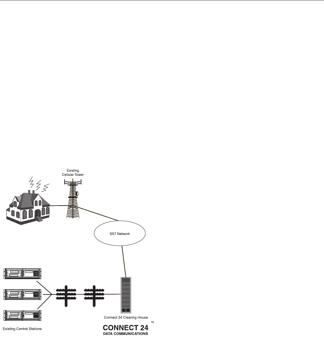
3.1 Cellemetry Communication
The Skyroute transceiver communicates using the control
channel of the existing cellular network. Signals are routed to
the Cellemetry Gateway via the SS7 cellular network. A clear-
ing house then receives the signals and forwards the events to
the central station. Upon receiving an acknowledgement signal
from the central station, the clearing house then returns a con-
firmation of delivery signal to the Skyroute transceiver over
the network. For transmission sequence see drawing below:
• The Skyroute transceiver reads the system activity directly
from the Keybus. It also sends the corresponding signals
over the cellular network, depending on what you have pro-
grammed the Skyroute transceiver to send.
• The Skyroute transceiver can be reprogrammed for full, backup
or generic reporting (see Sections 6.1 and 7.1 ‘Defaulting’).
• The Skyroute transceiver does not consider the signal to be
received at the central station until it receives confirmation
from the clearing house. Relay between signals can be up to
60 seconds apart.
NOTE: While the panel is in walk test mode, the Sky-
route will still communicate all alarms.
3.2 Skyroute Reporting Methods
Reporting via Skyroute is in addition to landline communica-
tions. Land line communications are unaffected by which
reporting method the Skyroute is using. A default of the Sky-
route must be performed before activation (Enter 00, 11 or 22
in sub-section [99] ‘Software Defaulting of the Skyroute’).
This is necessary to configure the Skyroute for one of the four
possible reporting methods:
1: ‘Full Reporting’ (Enter 00 in sub-section [99])
2: ‘Generic Reporting’ (Enter 12 in sub-section [99])
3: ‘Generic Reporting with fallback to Full Reporting’ (Enter
11 in sub-section [99])
4: ‘Backup Reporting’ (Enter 03 in sub-section [99])
Other important things to note:
• For an event to report via the Skyroute, the event reporting
code in sections [30]-[78] must be programmed as [FF] and
the associated ‘Transmission Option’ (in section [22]) must
be enabled.
• To disable a specific event from reporting via the Skyroute,
program the reporting code as [00].
• To disable a group of reporting codes from reporting via the
Skyroute, turn OFF the respective ‘Transmisison Option’ in
section [22].
• The Skyroute does not follow the ‘Event Buffer Follows
Swinger Shutdown’ option in the control panel.
3.2.1 Full Reporting
(Enter 00 in sub-section [99])
All events in sections [30]-[78] are automatically programmed
as [FF] and will be sent by the Skyroute. To disable a specific
event from sending via the Skyroute, program the reporting
code as [00]. To disable a group of reporting codes from send-
ing via the Skyroute, Turn OFF the respective ‘Transmisison
Option’ in section [22].
When using ‘Full Reporting’ it is very important to understand
that when multiple signals need to be sent, there is approxi-
mately a one-minute delay between each signal sent via the
Skyroute. Because of this delay, the Skyroute will buffer sig-
nals when multiple events occur and transmit them in the order
received.
For example; if you need to send 4 signals (i.e. alarm zone 1,
alarm restore zone 1, alarm zone 2, alarm restore zone 2), it
will take approximately 4 minutes for the Skyroute to send all
4 signals. The first signal sends immediately, then the remain-
ing three signals are each sent approximately 1 minute apart in
the order that they occurred.
When using Full Reporting, the central station will receive the
same signal from the panel via landline communications and
from the panel via Skyroute Communications. This is why it is
important to contact your central station regarding dual signal
communication. The automation system at the central station
must be able to suppress redundant signals.
3.2.2 Generic Reporting
(Enter 12 sub-section [99])
Generic Reporting is used to avoid duplicate alarm signals from
being received at the central station. It also avoids the large
delays between landline signals and Skyroute signals that occur
when multiple events of the same type happen within a short
time period (both of which occur when using ‘Full Reporting’).
Generic reporting only applies to certain types of alarm events.
These events are grouped together into one of 4 categories.
Each category has a specific alarm reporting code. When one
of these alarms occur, the Skyroute will send the associated
alarm reporting code for the category the alarm belongs to –
and then start a timer for that category (5 minutes at default
programmed in section [21]). If another alarm occurs in the
same category while its timer is active, then no signal is gener-
ated via the Skyroute for that category. If an alarm occurs in a
different category, then the Skyroute will send the associated
alarm reporting code for that category – and then start a timer
for that category (5 minutes at default – programmed in section
[21]). Each category has it’s own timer. If a new alarm event
occurs after the timer has expired for its category, the sequence

4
restarts. All events that are not included in one of the 4 catego-
ries (noted below) will be fully transmitted by the Skyroute (if
the associated reporting codes are programmed and ‘Transmis-
sion Options’ are ON).
While in Generic Mode, the panel will group the following
alarm events together as follows:
• Burglary: Delay 1, Delay 2, Instant, Interior, Interior Stay/
Away, Delay Stay/Away, 24 Hour Burglary, 24 Hour Latch-
ing Tamper, Momentary Keyswitch Arm, Maintained Key-
switch Arm, Links Answer
• Fire: Delayed Fire, Standard Fire, Delayed Fire (wireless),
Standard Fire (wireless), 2-Wire Smoke (PGM2), Keypad
Fire.
• Supervisory: 24 Hour Supervisory Buzzer, Silent 24 Hr
(PGM2), Audible 24 Hr (PGM2), Zone Expander Supervi-
sory Alarm.
• Panic: 24 Hour Panic, Keypad Panic
Generic Signals
3.2.3 Generic Reporting with Fallback to Full Reporting
(Enter 11 in sub-section [99])
Normally, the Skyroute will use ‘Generic Reporting’ (described
earlier). At any time if the Skyroute receives either a FTC (Fail-
ure to Communicate) or a TLM (Telephone Line Monitor) trou-
ble from the main panel via the Keybus, the Skyroute will
switch into ‘Full Reporting’ and send alarm signals as outlined
above in ‘Temporary Full Reporting’ (Note: When using
‘Generic Reporting with Fallback to Full Reporting’ and the
Skyroute switches to ‘Full Reporting’ upon receiving and ‘FTC’
or ‘TLM’ from the panel, the Skyroute will transmit the alarm
signals with the specific zone numbers without restorals).
When the Skyroute switches into ‘Full Reporting’, the FTC or
TLM trouble will be the first signal sent by the Skyroute. For
the Skyroute to switch back into ‘Generic Reporting’, the TLM
or FTC trouble must restore and a signal must be received by
the Skyroute from the main panel via the Keybus.
Upon restoral of the TLM or FTC Trouble, any signals that
occurred before the TLM or FTC trouble restored that still
need to be transmitted will be sent via the Skyroute until the
Skyroute’s communications buffer is empty. In addition, if new
alarms occur after switching back to ‘Generic Reporting’ while
full reporting events are still in the Skyroute’s communication
buffer, the Skyroute will generate the generic signal, place it at
the end of the communication buffer and function as outlined
above for ‘Generic Reporting’.
3.2.4 Backup Reporting
In Backup Reporting mode the Skyroute will only transmit
events when the panel is unable to transmit them. It must be
understood that the potential exists that in some situations
events may be duplicated on the landline, however when the
Skyroute is in backup mode it will attempt to not send events
that can be successfully transmitted over the phone line by the
panel.
Internally in the Skyroute, events are buffered with a times-
tamp. The timestamp is in intervals of 10 seconds yielding a
maximum time of approximately 42 minutes. The Backup
Timer Section[19] will control how long events will remain in
the buffer before they expire. If an event in the buffer expires
(ie. the timestamp on the event in the buffer is older than the
current timestamp) it will be deleted from the buffer. If an FTC
event is received from the Keybus, all events that have not
expired in the buffer will be transmitted, and the Skyroute will
temporarily go into full reporting mode. The Skyroute will
remain in full reporting mode until an FTC Restore event is
retrieved from the buffer. FTC and FTC Restore will also be
transmitted. The Skyroute will then return to Backup mode.
TLM Trouble and TLM Trouble restore events will always be
transmitted, and any events that are generated by the panel in
between these events will also always be transmitted.
It is important to program the Backup Timer Section [19] to a
Value that correlates to the amount of time it will take for the
panel to FTC. If the panel takes longer to FTC than is pro-
grammed in Section [19], then events may expire and no trans-
mission by the Skyroute will occur. If the panel takes less time
to FTC than is programmed into Section [19] then duplicate
events may occur. It is suggested to reduce the panel's number
of dialing attempts to 5 (refer to the Panel's programming), in
order to reduce the time it takes before the Skyroute will
switch into Full Reporting. The following table can be used to
help determine what value should be used in Section [19].
NOTE: This table refers to panel programming, with
the default values for dialing the receiver. If program-
ming has been done in the panel (for example, Post-
Dial Wait for Handshake or Delay Between Dialing
Attempts), then the values used in the Skyroute must
reflect these changes by adding the difference in pro-
grammed time to section [19] of the Skyroute.
If the panel is programmed for two phone numbers, then Sec-
tion [19] should be doubled from what is shown.
The types of events that trigger the Skyroute to temporarily
switch into full reporting mode can be configured in the
Backup FTC options, in Section [18].
NOTE: Do not use backup mode for Commercial Fire
or Commercial Burglary installations. Use only in UL
Residential Fire or Burglary installations.
SIA Contact ID
Burglary Partition x Event BA
zone 98
Partition x Event 130
zone 098
Fire Partition x Event FA
zone 98
Partition x Event 110
zone 098
Supervisory Partition x Event US
zone 98
Partition x Event 140
zone 098
Panic Partition x Event PA
zone 98
Partition x Event 120
zone 098
Panel's Max
Dialing
Attempts
Total Panel
Time
Value to Program
into Section [19]
1 90 seconds 09 (9 decimal)
5 450 seconds 2D (45 decimal)
8 720 seconds 48 (72 decimal)

5
Section 4 - What Do I Do before Installing a Skyroute Transceiver?
CONNECT 24 is your Skyroute Cellemetry service provider.
If you have not yet enrolled as a Skyroute dealer, you must do so at least 1 business day before your first Skyroute installation.
NOTE: If you do not have the numbers required below, please call Connect 24 at 1-888-955-5583 in Canada or 1-888-251-7458
in the U.S. “Dealer Enrolment”.
Activation of your Skyroute transmitter can be accomplished in minutes, at any time 24 hours a day, 365 days a year, by calling our toll-free CON-
NECT 24 Voice Response Unit at 877-759-7688 (Canada) or 888-251-7554 (U.S.). This guide will provide you with an example of what to
expect when you are using the VRU.
Before you begin, make sure you have all of the information that you will need to enter into the VRU system.
What you will need…
•The Profile Number for your installation
The Profile Number represents the Central Station Receiver/Rate Plan
combination and the communication format you are using. Make sure
that you know which profile number to use when doing an installation.
• Your Installer ID Number
Each individual installer who was listed on your Dealer Enrolment Form
was given a unique Installer ID Number. This number can be found on
the Authorized Installer Card sent with the Dealer Confirmation Form.
• Your Installer PIN
Each installer is provided a four digit Personal Identification Number
(PIN) on the Dealer Enrolment Form. If you have forgotten your PIN,
please contact CONNECT 24.
•The Central Station Account Number for the alarm system
This is the account number you wish to be transmitted to the central sta-
tion. If the profile is set to send SIA format, enter a maximum of six dig-
its; if Contact ID format, enter a maximum of four digits.
•The Skyroute MIN (Mobile Identification Number)
The MIN identifies the Skyroute transmitter. The 10-digit MIN is
located on the label affixed to your Skyroute transmitter.
•The System ID Number (SID) for the cellular provider in your area
The five-digit System ID Number tells CONNECT 24 (and the cellular
network) the home area in which your transmitter is installed. When you
program this number into the DSC alarm panel, it is entered in HEX for-
mat. However, when entering this number into the CONNECT 24 VRU,
it is entered in DECIMAL format.
NOTE: For US locations, please refer to the “U.S.A SID List -
By State” document which comes with each Skyroute trans-
ceiver as a separate booklet.
6
Section 5 - Installing a Skyroute Transceiver
Time-Saving Tips: By powering up the Skyroute transceiver on a battery alone (battery red to Bell In and Keybus red, battery black to
Keybus black), you can quickly determine a location where your signal strength is strong prior to installing the unit. The Skyroute unit
does not have to be active to show signal strength.
5.1 Location of the Skyroute Unit
It is very important to determine the best location for maximum signal strength.
Verify signal strength prior to installation!
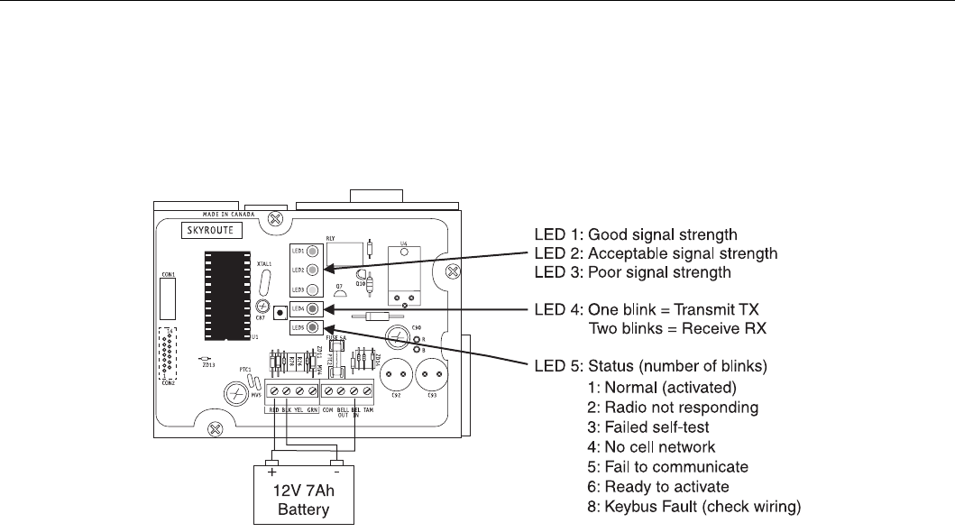
1: Normal (activated) The radio is operating normally and
there are no troubles with the Skyroute.
2: Radio not Responding Possible causes; the radio in the
Skyroute is not powered up, the initialization of cellemetry
radio has failed, an internal problem with the radio, bad data
connections between the radio and the panel.
3: Failed self-test A self-test of the cellemetry module has failed.
4: No cell network The cellemetry modem has failed to regis-
ter with the cellular network (Ie. no network coverage or
very weak signal).
5: Failure to communicate The Skyroute has not successfully
communicated a signal to the central station (the Skyroute
has not received the acknowledgement that the central sta-
tion successfully received a signal).
6: Ready to Activate The Skyrotue has not been activated
with Connect 24.
8: Keybus Fault The Skyroute cannot communicate to the panel.
NOTE: If there is a Skyroute trouble, the panel it is
connected to will display a ‘General System Supervi-
sory’ trouble.
NOTE: If the [TAM] to [COM] terminals are open on
the Skyroute, the panel it is connected to will display
a ‘General System Tamper’ trouble.
5.2 Relocating the Skyroute Transceiver
Since the Skyroute transceiver is a Keybus accessory, it is pos-
sible to relocate the module up to 150 feet (45.4 m) from the
main control panel when the panel is not located in a good Cel-
lemetry coverage area (a control panel installed in a vault for
example). When relocating the module, follow theses rules:
• Maximum of 150 feet (45.4 m) from the main control. Key-
bus (Red, Black, Yellow, Green) from the panel to the Sky-
route transceiver.
• A UL1481 Listed power supply 12V@1.5A must be used for
UL installations.
• The power supply (+ positive) is connected to the Skyroute
transceiver (BELL IN) terminal and the power supply (–
negative) to the Skyroute transceiver (COM) terminal.
• The cabinet must be installed in a secure location and should
have a tamper circuit connected to the Skyroute (TAM and
COM) terminals.
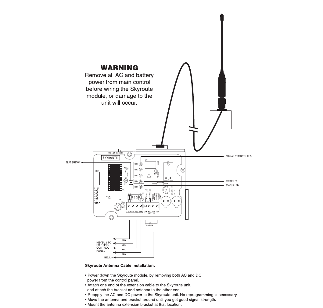
5.3 Relocating the Antenna
If a suitable location is not available for proper Cellemetry cov-
erage, obtain an Antenna Extension Bracket Kit from your DSC
supplier. Each kit contains an extension cable, a mounting
bracket, instructions, and all required hardware. Three lengths of
extension cable are available:
Only use the Extension Kits to extend the mounting range
of the antenna. Do not cut or splice the extension cable. The
maximum distance between the Skyroute transceiver and the
antenna is 25 feet (7.62 m) as obtained by using the LAE-25 or
SKR-025 Extension Kit. Make sure the antenna is in a physi-
cally secured location to avoid tampering.
Secure the TNC connector from the Extension Kit to the
mounting bracket, ensuring that the star washers make solid
electrical contact with the mounting bracket.
Remove the antenna from the Skyroute module and connect the
extension cable to the TNC connector on the module. Secure the
antenna to the TNC connector mounted on the Extension Kit
mounting bracket. Locate the mounting bracket and antenna away
from possible sources of electrical interference. Moving the
antenna just a short distance will likely be adequate. Temporarily
secure the mounting bracket in the new location and proceed with
testing. If the test is successful, permanently secure the mounting
bracket and antenna at the new location.
Extension Kit Length of cable
LAE-3 3 feet (0.91 m)
LAE-15 15 feet (4.57 m)
LAE-25 25 feet (7.62 m)
SKR-025 25 feet (7.62m)
7
Antenna Relocation Diagram
5.4 UL Requirements
5.4.1 Grade A - Central Station Service, Residential Fire
and Burglary Installations
• Programming [13] - Option 2 Test Rates must be “ON”.
• Every 24 hours a check-in signal must be sent to the central
station. Refer to compatible Listed control unit’s installation
instructions for programming.
• Dialing attempts must be programmed for 5 to 10 attempts.
Skyroute transmitter makes 3 attempts by default. Refer to
compatible Listed control unit’s installation instructions for
programming.
• The response wait time, section [24] should be set to 09.
• Alarm signals must be sent over both primary and secondary
communication paths -
1. Compatible Listed control unit’s land line to central sta-
tion (primary).
2. Skyroute transmission through Cellemetry to the clearing
house (Connect 24) (secondary).
• DACT must be enabled for Listed compatible control unit.
5.4.2 Police Station Connect with Basic Line Security
• Same as Grade A Central Station Installations.
5.4.3 Commercial Fire Installations
• Same as Grade A Central Station Installations.
• The BELL+ and BELL- terminals on the control panel shall
not power other devices. Refer to Compatible Listed control
unit installation instructions for wiring and programming.
5.4.4 Back-up Reporting Mode (03)
• To be used only for UL/ULC residential Fire and Burglary
applications.
5.4.5 For ULC Installations
• The redundant Communication mode (00) meets level 2 line
security requirements.
Antenna Extension Kits
LAE-3 3-ft. (0.9m) extension kit
LAE-15
LAE-25
SKR-025
15-ft. (4.6m) extension kit
25-ft. (7.6m) extension kit
25-ft. (7.6m) extension kit (external)
8
5.5 Installation
It is mandatory that the power be removed from the system
before any wiring changes are performed on the Skyroute
module. Neglecting to do so will result in damage to the Sky-
route transceiver.
5.6 Mounting the Skyroute Transceiver
The Skyroute transceiver can be mounted in the upper right
hand corner of the panel’s cabinet through the knockout. The
Skyroute transceiver case attaches to the panel’s cabinet
through the use of clips and two screws.
5.7 Mounting the Antenna
NOTE: The antenna should always be attached to the
Skyroute transceiver for proper operation. The unit will
not function properly and/or be damaged if the
antenna is not installed.
The antenna attaches to the TNC connector of the Skyroute
transceiver. The antenna should be mounted as high above
ground level as possible while at the same time care should be
taken not to place the antenna under a radio frequency shield of
any kind. For example, do not mount the antenna directly
below a metal roofing overhang. The Skyroute transceiver
functions best when installed in an unobstructed line of sight to
the cellular antenna site.
5.8 Keybus Connection
The Skyroute transmitter has 4 terminals marked red, black,
yellow and green. Connect these four terminals to the 4 termi-
nals on the main control panel marked Keybus (red, black, yel-
low and green).
5.9 Bell IN Terminal
This terminal is used to power the Cellemetry modem of the
Skyroute module. This connects to the BELL + on the control
panel. No other wire should be connected to the Bell+ of the
control panel.
An extra power supply can be used to power the modem if it is
not located near the main control panel or is located where the
system cannot provide enough power for the transmissions.
Connect the positive of the power supply to the BELL IN and
the negative to the COM to ensure proper grounding (see dia-
gram on this page).
5.10 Bell OUT Terminal
This terminal is used to power the siren or any other devices
that would usually connect to the control panel BELL+ termi-
nal. This output is powered through the 5A fuse for protection
of the radio transmitting power.
5.11 Tamper Terminal
Connect TAM and COM to a normally closed switch that will
be used to monitor tamper. If no tamper switch is desired place
a wire between TAM and COM.
5.12 Secure Installation
For a secure installation, the Skyroute transceiver and its host
panel must be locked and protected. An instant trip IR sensor
would be the most appropriate for supervision of the panel. A
cabinet tamper switch connected to the TAM terminal of the
Skyroute transceiver is also suggested.
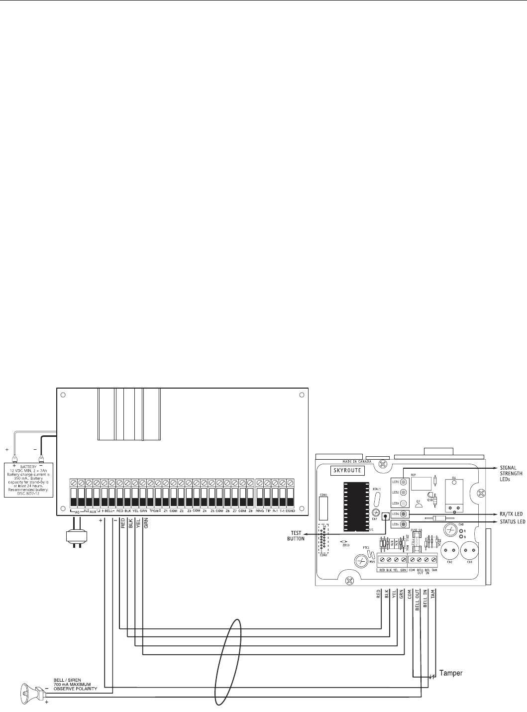
5.13 Connection Diagrams
Standard Connection with Compatible Control Panels (Non-Commercial Fire Applications)
CONTROL PANEL
150' / 45.45 m max.
150' / 45.45 m max.
WARNING
Remove all AC and battery
power from main control panel
before wiring the Skyroute
module, or damage to the
unit will occur.
DSC panel minimum
power requirements:
16 VAC 40 VA transformer
12 VDC 7 Ah battery
Keybus to all modules
Refer to the Installation
Manual for detailed
information on wiring.
Be sure to observe polarity
when connecting polarized
sirens or bells
UL Listed Class II
Transformer
16.5 V @ 40 VA
Recommended:
DSC PTD1640U
Do not connect
transformer to receptacle
controlled by a switch. The
transformer must be UL
Listed and have a
restraining means.
120V 60Hz
UL LISTED
Bell Loop
700 mA Max.
RED BLK
9
Standard Connection with PC5020CF / Partner P-8+CF (Commercial Fire Applications)
Skyroute
Skyroute
Skyroute
Skyroute
Keybus
Skyroute
Skyroute
Skyroute
Skyroute
Skyroute place.
Wiring Skyroute to a DSC PC5020CF/P-8+CF
NOTE: For commercial
Fire Applications DO NOT
connect any devices on
the "BELL+" terminal
(PC5020CF) other than the
Skyroute module.
CONTROL PANEL
KEYBUS TO ALL MODULES
Refer to the Installation Manual for
detailed information on wiring.
WARNING!
All connections to the Skyroute module are power limited. Do not route any wiring over the circuit
boards. Maintain at least 1” (25.4mm) separation between circuit board and wiring.
A minimum of 1/4” (7mm) separation must be maintained at all points between non power limited
wiring and power limited wiring.
Refer to your control panel Installation Manual for any additional information.
DC
REDBELL
++
AUX ––
AC BLK YEL GRN Z1 Z3 Z5 Z7COM COM COM COMZ2 Z4 Z6 Z8 RING TIP R-1 T-1 EGNDPGM
1324
RED BLK
PC-Link Connection
SI SO
Supervised
PTC
10
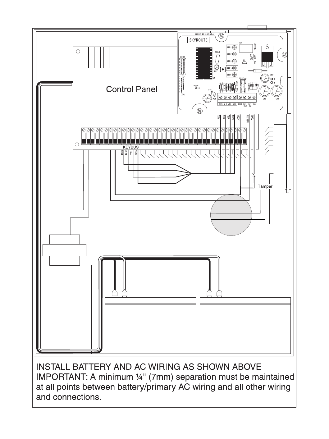
Battery Lead and AC Power Lead Routing for UL Listed Commercial Fire Systems
11
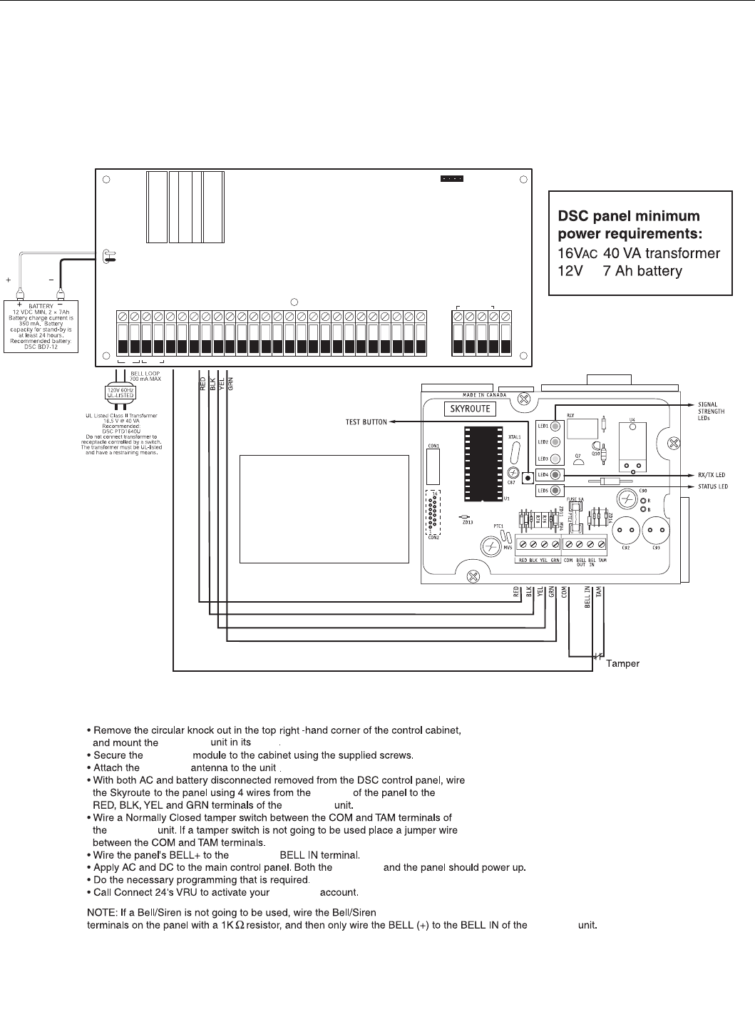
5.14 Wiring Skyroute to a DSC/Partner Control
Panel
• Remove the circular knockout in the top left corner of the
control panel cabinet. Mount the Skyroute unit in its place.
• Secure the Skyroute module to the cabinet using the supplied
screws.
• Attach the Skyroute antenna to the unit.
• Disconnect and remove the AC and battery power from the
control panel. Wire the red, black, yellow and green wires
from the panel Keybus to the corresponding RED, BLK,
YEL and GRN terminals on the Skyroute transceiver.
• Wire a normally closed tamper switch between the COM and
TAM terminals of the Skyroute module. If a tamper switch is
not going to be used, place a jumper wire between the COM
and TAM terminals.
• Wire the BELL+ terminal of the panel to the BELL IN ter-
minal of the Skyroute unit. The wire run must not exceed
150 ft. / 45.5 m.
• Wire the BELL- terminal of the panel to the negative (-) ter-
minal of the bell/siren.
• Wire the BELL+/SIREN+ terminal of the bell/siren to the
BELL OUT terminal of the Skyroute transceiver.
• Apply AC and DC power to the control panel. Power up both
the Skyroute module and the panel.
• Do the programming if it is required.
• Call the Connect 24 VRU (Voice Reponse Unit) to activate
your Skyroute account.
NOTE: If a bell or siren is not going to be used in the
system, wire the BELL/SIREN terminals on the panel
with a 1000 Ohm resistor. Then wire only the BELL+
terminal of the panel to the BELL IN terminal of the
Skyroute module.
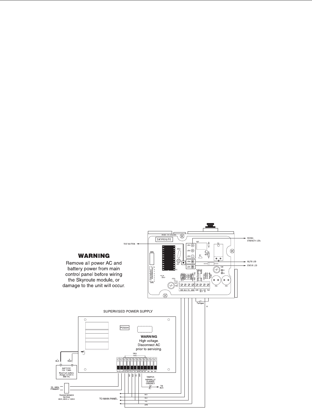
5.15 Supervised Power Supply Connection
Power Requirements
The PC5204 power supply requires a 16V, 40 VA transformer
and a 12V, 7 Ah battery.
NOTE: If a battery is not connected to the PC5204
power supply, an expansion trouble and a restoral will
be generated every time a signal is transmitted.
Connections
• The Keybus from the panel is connected to both the PC5204
module and the Skyroute transceiver.
• A wire is connected from the AUX terminal on the PC5204
module to the BELL IN of the Skyroute transceiver.
• A jumper or a normally closed switch is required between
the TAM and the COM terminals on the Skyroute trans-
ceiver.
• A jumper or a normally closed switch is required between
the TAM and the BLK terminals for the tamper of the
PC5204 power supply.
• Wire the positive lead of the device to the AUX+ terminal.
• Connect a 1000 Ohm resistor between AUX+ and O1 termi-
nals.
NOTE: for secure installation a tamper switch must be
installed on the Skyroute module.
Using the PC5204 power supply module for this con-
figuration is not UL Listed. A UL1481 Listed power
supply (e.g., PS5350) must be used.

12
Section 6 - Programming and Activating a Skyroute
6.1 Defaulting
NOTE: This product must be defaulted BEFORE pro-
gramming/activating.
Select the type of default as follows:
6.1.1 Full Reporting
• Entering 00 in sub-section [99]
1. A complete default of the system is performed
2. All reporting sub-sections, [30] through [78] are automat-
ically programmed as [FF] and will be sent by the Sky-
route transceiver.
6.1.2 Generic Reporting with Fallback to Full Reporting
• Entering 11 in sub-section [99]*
1. A complete default is performed.
2. Reduced Reporting as follows:
Reduced Reporting
1. Alarm Restoral Reporting Code, sub-sections [34]
through [38], will be automatically programmed to [00],
except the duress alarm.
2. The Keypad and PGM Restorals in section [39] will be
programmed to [00]. Zone Tamper & Restoral reporting
code, sub-sections [40] through [48], will be programmed
to [00]**.
3. Zone Supervisory & Restoral, sub-sections [49] through
[56], will be programmed to [00]**.
4. Zone Low Battery Alarm & Restoral, sub-sections [57]
through [64], will be programmed to [00]***.
5. Keypad Zone Restoral, sub-section [39], last 4 program-
ming locations, will be programmed as [00].
6. Miscellaneous Restoral and Periodic Test in sections [77]
and [78] will be programmed as [00].
In Generic mode, see Appendix A for Generic signals. (See
Section 3 ‘How Does It Work?’ for description of each report-
ing method).
6.1.3 Generic Reporting
• Entering 12 in sub-section [99]*
1. A complete default is performed
2. Reduced Reporting as indicated above.
In Generic mode, see Appendix A for Generic signals. (See
Section 3 ‘How Does It Work?’ for description of each report-
ing method.)
6.1.4 Backup Reporting
• Entering 03 in sub-section [99]
1. A complete default is performed.
2. All reporting sub-sections [30] to [78] are automatically pro-
grammed as [FF] and will be sent by the Skyroute Transceiver.
• Entering 13 in sub-section [99].
1. A complete default is performed.
2. The Skyroute will be programmed for backup mode.
6.2 Programming Options
All programming on the Skyroute transceiver is done in the
Installer Programming mode. Refer to the control panel’s
Installation Manual for instructions on how to enter Installer
Programming. From Installer Programming, enter section
[803] to go to the Skyroute programming sections.
Sub-sections [01] to [22] apply to all other installations.
6.2.1 Basic Programming
Zone Definition: Sub-sections [01] to [05]
These sections must be programmed exactly the same as the
main control panel. This allows the Skyroute transceiver to
translate information sent along the Keybus and identify the
proper event.
NOTE: The Skyroute module will not follow any zone
transmission delays; i.e., any zones programmed with
a delay will be sent immediately by the Skyroute
transceiver.
Configuration Options: Sub-section [06]
• Channel A enable/disable…………..option [1]
This option must be selected when the Cellemetry provider
is an “A” side carrier.
• Channel B enable/disable…………..option[2]
This option must be selected when the Cellemetry provider
is a “B” side carrier.
• Home system only enable/disable…option[3]
This option must be programmed to ensure that the Skyroute
transceiver is communicating using the proper carrier. When
selected, the transceiver will only use towers with the same
SID (as programmed in section [07]).
NOTE: For US locations please refer to ‘U.S.A. SID List -
By State’. For Canadian locations please select channel B.
• To activate the Skyroute module in Home mode:
1. Select a channel, A or B, in address 06 (Option 1 or 2)
2. Wait for signal strength.
3. Enter in address 07 the Home SID number in hexadecimal
format.
4. Select Home mode (Option 3) and deactivate A or B chan-
nel in address 06.
NOTE: After changing sub-section [06] or [07] a
restart is required. Enter [*FF] in section [99].
Skyroute transceiver SID (System ID):
Sub-section [07]
Please refer to the SID table included with the Skyroute mod-
ule to determine the SID number for your area.
Skyroute Test Time: Sub-section [10]
In this section enter the time of the day (24-hour format) you
want the test transmission to be sent.
Test Transmission Day Mask: Section [11]
In this section select the day of the week on which you want
the test transmission to be sent.
NOTE: This option cannot be used for UL Listed instal-
lations.
* Any reporting code sub-section not mentioned is pro-
grammed as [FF].
** These signals only apply to installations with double EOL.
*** These signals only apply to installations with wireless zone
modules.

13
Skyroute Test Rates: Sub-section [13]
• Option 1- Not used.
• Option 2- Daily Test: If this option is ON, the Skyroute will
self-generate a ‘Skyroute Test Transmission’ signal (TX-00
or E603-000) every day.
• Option 3- Weekly Test: If this option is ON, the Skyroute
will self-generate a ‘Skyroute Test Transmission’ signal
(TX-00 or E603-000) every week.
• Option 4 – Keybus Tests Enabled: If this option is ON, the
Skyroute will send a ‘Periodic Test Transmission’ signal
(RP-00 or E602-000) at the same time the main panel sends
its ‘Periodic Test Transmission’ via the land line.
Backup FTC Options: Sub-section [18]
All FTC or Trouble conditions must be restored for the Sky-
route to return to backup mode. All trouble conditions that
caused the Skyroute to switch to Temporary Full Reporting
Mode must be restored before it returns to Backup Mode.
Backup Mode Timer: Sub-section [19]
This option should correlate with the timing set in the panel.
Refer to Panel Programming documentation and 3.2.4.
Generic Signal Timer: Sub-section [21]
This is the timer used by Generic Reporting. See Section 3 for
more information.
Transmission Options: Sub-section [22]
This section will enable sections of reporting codes. (See table
for different service plans.)
Refer to Appendices Aand B to find out which reporting codes
are controlled by each transmission option.
6.2.2 Advanced Programming
Individual Event: Sub-sections [30] to [78]
These sections are used to determine if an event will be trans-
mitted by the Skyroute transceiver. If ’00’ is entered, that event
will not be transmitted. If ‘FF’ is programmed, the event will
be transmitted. ‘FF’ is the default value.
The Skyroute module will send these events when they occur
in the system unless they are programmed as ‘00’. Refer to
Appendices A and B for more information.
6.3 Activating a Skyroute Transceiver
Before activating the Skyroute transceiver, ensure that the con-
trol panel is wired, programmed and operating properly. Make
sure that the Skyroute transmitter is properly connected to the
Keybus and to the bell (+ positive) circuit. When power is
applied to the system, the Skyroute transceiver will perform
self-diagnostics for a few seconds, before giving visual feed-
back by indicating signal strength on LED1, LED2 or LED3.
6.3.1 Calling Connect 24
Once the Skyroute transceiver is indicating the signal strength
of the network, and the status indicator (LED5) is blinking 6
times (not connected to the clearing house), you are ready to
call Connect 24’s Voice Response Unit. Follow the voice
prompt and when asked to perform a test, press SW1 on the
Skyroute transceiver to transmit a test signal. When transmit-
ting, LED4 blinks once. If the test is successful, the VRU will
give you a confirmation and LED5 will then blink steady every
second. Refer to the Connect 24 information package for more
information on the activation process.
NOTE: The confirmation of a successful test from Con-
nect 24 does not guarantee proper transmission of
the event to your central station. You must perform
normal tests with your central station after activation
with Connect 24.
6.3.2 Transmitting and Receiving
LED4 on the Skyroute module will blink once (1) to indicate
the cellular tower has received the signal. It will blink twice
(2) to indicate the alarm central station has received and
acknowledged the signal.
6.3.3 Skyroute Transceiver Trouble Supervision
The Skyroute transceiver automatically monitors its operation
and indicates trouble conditions by flashing LED5 on the cir-
cuit board. LED5 normally flashes once every 2 seconds when
the Skyroute transceiver is on standby (ready to transmit)
mode. Troubles are indicated when LED5 flashes more than
once every 2 seconds. See Section 5.1 ‘Location of the Sky-
route Unit’ for the number of flashes used to indicate each
trouble condition in order of importance.
1E I___I___I (hex) (number x 10 seconds)
Generic
Reporting
Full
Reporting Option
ON ON I___I 1Alarms
/Restoral
Disabled
OFF ON I___I 2 Tamper Resto-
ral/Restoral
Disabled
OFF ON I___I 3 Supervisory/
Restoral
Disabled
OFF ON I___I 4 Low Battery/
Restoral
Disabled
OFF OFF I___I 5 Opening/
Closing
Disabled
ON ON I___I 6 Maintenance/
Restoral
Disabled
OFF OFF I___I 7 & 8 Not Used

14
Section 7 - [803] Skyroute Programming Worksheets
(PC5020/PC5010/PC580/1PC555/PC5015/P-832/P-48/P-6B/P-832DL)
7.1 Defaulting
A default must be performed before activating the Skyroute transceiver. For UL Listed installations, refer to the compatible control
panel Installation Manual for programming the number of panel attempts. The number of attempts between the Skyroute and the
panel must be between 5 to 10 attempts. The Skyroute transceiver’s default is 3 attempts.
[99] Section [99] is for software defaulting of the Skyroute module
• Entering 00 will cause a software default of the Skyroute
module to Full Reporting.
• Entering 11 will cause a software default of the Skyroute
module and Generic reporting with fall-back to Full report-
ing if TLM or FTC trouble occurs.
• Entering 12 will cause a software default of the Skyroute
module and Generic reporting.
• Entering FF will cause restart of the Skyroute transceiver.
• Entering 03 will cause a software default of the Skyroute
module and Backup Reporting.
7.2 Basic Programming
Zone Definitions
[01] Zone 1-16 Definitions
[02] Zone 17-32 Definitions
[03] Zone 33-48 Definitions
[04] Zone 49-64 Definitions
I___I___I
00 Null Zone (Not Used) 12 24 Hour Holdup* 23 Maintained Keyswitch Arm*
01 Delay 1* 13 24 Hour Gas* 24 LINKS1000 Answer*
02 Delay 2* 14 24 Hour Heating* 25 Interior Delay*
03 Instant* 15 24 Hour Auxiliary* 26 24 Hour Non-alarm*
04 Interior* 16 24 Hour Panic* 27 Delayed 24 Hour Waterflow
05 Interior, Stay/Away* 17 24 Hour Emergency* 28 Instant 24 Hour Waterflow
06 Delay, Stay/Away* 18 24 Hour Sprinkler* 29 Auto Verified Fire
07 Delayed 24 Hour Fire (Hardwired)** 19 24 Hour Water* 30 Fire Supervisory
08 Standard 24 Hour Fire (Hardwired) 20 24 Hour Freeze* 31 Day Zone*
09 24 Hour Supervisory 21 24 Hour Latching Tamper* 87 Delay 24 Hour Fire (Wireless)**
10 24 Hour Supervisory Buzzer* 22 Momentary Keyswitch Arm* 88 Standard 24 Hour Fire (Wireless)**
11 24 Hour Burglary*
*For burglary applications only
** For residential fire applications only
Default Default Default Default
00 I___I___I Zone 1 00 I___I___I Zone 5 00 I___I___I Zone 9 00 I___I___I Zone 13
00 I___I___I Zone 2 00 I___I___I Zone 6 00 I___I___I Zone 10 00 I___I___I Zone 14
00 I___I___I Zone 3 00 I___I___I Zone 7 00 I___I___I Zone 11 00 I___I___I Zone 15
00 I___I___I Zone 4 00 I___I___I Zone 8 00 I___I___I Zone 12 00 I___I___I Zone 16
Default Default Default Default
00 I___I___I Zone 17 00 I___I___I Zone 21 00 I___I___I Zone 25 00 I___I___I Zone 29
00 I___I___I Zone 18 00 I___I___I Zone 22 00 I___I___I Zone 26 00 I___I___I Zone 30
00 I___I___I Zone 19 00 I___I___I Zone 23 00 I___I___I Zone 27 00 I___I___I Zone 31
00 I___I___I Zone 20 00 I___I___I Zone 24 00 I___I___I Zone 28 00 I___I___I Zone 32
Default Default Default Default
00 I___I___I Zone 33 00 I___I___I Zone 37 00 I___I___I Zone 41 00 I___I___I Zone 45
00 I___I___I Zone 34 00 I___I___I Zone 38 00 I___I___I Zone 42 00 I___I___I Zone 46
00 I___I___I Zone 35 00 I___I___I Zone 39 00 I___I___I Zone 43 00 I___I___I Zone 47
00 I___I___I Zone 36 00 I___I___I Zone 40 00 I___I___I Zone 44 00 I___I___I Zone 48
Default Default Default Default
00 I___I___I Zone 49 00 I___I___I Zone 53 00 I___I___I Zone 57 00 I___I___I Zone 61
00 I___I___I Zone 50 00 I___I___I Zone 54 00 I___I___I Zone 58 00 I___I___I Zone 62
00 I___I___I Zone 51 00 I___I___I Zone 55 00 I___I___I Zone 59 00 I___I___I Zone 63
00 I___I___I Zone 52 00 I___I___I Zone 56 00 I___I___I Zone 60 00 I___I___I Zone 64

15
[05] PGM2 Definition
[06] Skyroute Configuration Options
[07] Home SID Number
[10] Skyroute Test Time
[11] Test Transmission Day Mask - This section is not to be used for UL Listed applications.
[13] Skyroute Test Rates
[18] Backup FTC Options
[19] Backup Reporting Mode Timer
[20] Communication Mode
This section will display the mode in which the Skyroute operates. To change the mode refer to section [99].
•00 - Skyroute module is in Full Reporting Mode
•11 - Skyroute module is in Generic Reporting with fall-back
to Full Reporting if TLM or FTC trouble occurs
•12 - Skyroute module is in Generic Reporting Mode
•03 - Skyroute module is in Backup Reporting Mode
00 I___I___I 04 = 2 Wire Smoke, 23 = silent 24 Hour Input, 24 = Audible 24 Hour Input.
Default Option ON Option OFF
OFF I___I Option 1 ‘A’ Channel Selected ‘A’ Channel Not Selected
ON I___I Option 2 ‘B’ Channel Selected ‘B’ Channel Not Selected
OFF I___I Option 3 Home System Only Not in Home System Operation
OFF I___I Option 4 Unit Active with Connect 24 Unit Not Active with Connect 24
OFF I___I Options 5 to 8 System Use - DO NOT CHANGE
0000 I___I___I___I___I This is the SID (in Hex) of the cellular service that is available on the current channel.
This section should be programmed ONLY if option 3 is turned ON in section [06].
9999 I___I___I___I___I 0000-2359 (in 24 hour time)
Default Option ON Option OFF
OFF I___I Option 1 Test on Sunday Disabled
OFF I___I Option 2 Test on Monday Disabled
OFF I___I Option 3 Test on Tuesday Disabled
OFF I___I Option 4 Test on Wednesday Disabled
OFF I___I Option 5 Test on Thursday Disabled
OFF I___I Option 6 Test on Friday Disabled
OFF I___I Option 7 Test on Saturday Disabled
OFF I___I Option 8 For Future Use
Default Option ON Option OFF
OFF I___I Option 1 Not used
OFF I___I Option 2* Daily Test Disabled
ON I___I Option 3 Weekly Test Disabled
OFF I___I Option 4 Keybus Tests Enabled Disabled
OFF I___I Options 5 to 8 For Future Use
* Option 2 must be ON for UL Listed applications.
Default Option ON Option OFF
ON I___I Option 1 FTC Phone #1 Backup Disabled
ON I___I Option 2 FTC Phone #2 Backup Disabled
OFF I___I Option 3* T-LINK Comm Fault Backup Disabled
OFF I___I Option 4* T-LINK Receiver Trb Backup Disabled
OFF I___I Options 5 to 8
* Options 3 and 4 may be used for Generic Reporting with Fall Back to full reporting mode if a T-Link is
the main communicator for the panel.
Default
42 I___I___I (number x 10 seconds in Hex)

16
[21] Generic Signal Timer
[22] Transmission Options
[23] Number of Attempts
[24] Response Wait Time
NOTE: For UL Installations, this section needs to be programmed as 09 for 90 seconds.
[90] Current Signal Strength Reading
BASIC PROGRAMMING COMPLETED
7.3 Advanced Programming
The following sub-sections (30 -78) have automatically been programmed. How they are programmed depends on how you default
the Skyroute (see Section 6.1). You may make changes if wanted.
Sub-sections [30] to [78]: If ’00’ is entered, reporting code is disabled.
If ‘FF’ is entered, default reporting code is enabled.
[30] Alarm Reporting Codes, Zones 1-16
[31] Alarm Reporting Codes, Zones 17-32
Default
1E I___I___I (number x 10 seconds in Hex)
Generic
Reporting
Full
Reporting Option ON Option OFF
ON ON I___I Option 1 Alarms/Restoral Disabled
OFF ON I___I Option 2 Tamper/Restores Disabled
OFF ON I___I Option 3 Supervisory/Restores Disabled
OFF ON I___I Option 4 Low Battery/Restores Disabled
OFF OFF I___I Option 5 Openings/Closings Disabled
ON ON I___I Option 6 Maintenance/Restoral Disabled
OFF OFF I___I Options 7 & 8 For Future Use
Default
03 I___I___I___I 00-FF (HEX)
Default
19 I___I___I___I (number x 10 seconds in Hex)
I___I___I___I This section will show the most recent Skyroute signal strength as a percentage from 0-100%.
Generic
Reporting
Full
Reporting
Generic
Reporting
Full
Reporting
FF FF I___I___I Zone 1 Alarm FF FF I___I___I Zone 9 Alarm
FF FF I___I___I Zone 2 Alarm FF FF I___I___I Zone 10 Alarm
FF FF I___I___I Zone 3 Alarm FF FF I___I___I Zone 11 Alarm
FF FF I___I___I Zone 4 Alarm FF FF I___I___I Zone 12 Alarm
FF FF I___I___I Zone 5 Alarm FF FF I___I___I Zone 13 Alarm
FF FF I___I___I Zone 6 Alarm FF FF I___I___I Zone 14 Alarm
FF FF I___I___I Zone 7 Alarm FF FF I___I___I Zone 15 Alarm
FF FF I___I___I Zone 8 Alarm FF FF I___I___I Zone 16 Alarm
Generic
Reporting
Full
Reporting
Generic
Reporting
Full
Reporting
FF FF I___I___I Zone 17 Alarm FF FF I___I___I Zone 25 Alarm
FF FF I___I___I Zone 18 Alarm FF FF I___I___I Zone 26 Alarm
FF FF I___I___I Zone 19 Alarm FF FF I___I___I Zone 27 Alarm
FF FF I___I___I Zone 20 Alarm FF FF I___I___I Zone 28 Alarm
FF FF I___I___I Zone 21 Alarm FF FF I___I___I Zone 29 Alarm
FF FF I___I___I Zone 22 Alarm FF FF I___I___I Zone 30 Alarm
FF FF I___I___I Zone 23 Alarm FF FF I___I___I Zone 31 Alarm
FF FF I___I___I Zone 24 Alarm FF FF I___I___I Zone 32 Alarm
OPTIONAL

17
[32] Alarm Reporting Codes, Zones 33-48
[33] Alarm Reporting Codes, Zones 49-64
[34] Alarm Restoral Reporting Codes, Zones 1-16
[35] Alarm Restoral Reporting Codes, Zones 17-32
[36] Alarm Restoral Reporting Codes, Zones 33-48
Generic
Reporting
Full
Reporting
Generic
Reporting
Full
Reporting
FF FF I___I___I Zone 33 Alarm FF FF I___I___I Zone 41 Alarm
FF FF I___I___I Zone 34 Alarm FF FF I___I___I Zone 42 Alarm
FF FF I___I___I Zone 35 Alarm FF FF I___I___I Zone 43 Alarm
FF FF I___I___I Zone 36 Alarm FF FF I___I___I Zone 44 Alarm
FF FF I___I___I Zone 37 Alarm FF FF I___I___I Zone 45 Alarm
FF FF I___I___I Zone 38 Alarm FF FF I___I___I Zone 46 Alarm
FF FF I___I___I Zone 39 Alarm FF FF I___I___I Zone 47 Alarm
FF FF I___I___I Zone 40 Alarm FF FF I___I___I Zone 48 Alarm
Generic
Reporting
Full
Reporting
Generic
Reporting
Full
Reporting
FF FF I___I___I Zone 49 Alarm FF FF I___I___I Zone 57 Alarm
FF FF I___I___I Zone 50 Alarm FF FF I___I___I Zone 58 Alarm
FF FF I___I___I Zone 51 Alarm FF FF I___I___I Zone 59 Alarm
FF FF I___I___I Zone 52 Alarm FF FF I___I___I Zone 60 Alarm
FF FF I___I___I Zone 53 Alarm FF FF I___I___I Zone 61 Alarm
FF FF I___I___I Zone 54 Alarm FF FF I___I___I Zone 62 Alarm
FF FF I___I___I Zone 55 Alarm FF FF I___I___I Zone 63 Alarm
FF FF I___I___I Zone 56 Alarm FF FF I___I___I Zone 64 Alarm
Generic
Reporting
Full
Reporting
Generic
Reporting
Full
Reporting
00 FF I___I___I Zone 1 Alarm Restoral 00 FF I___I___I Zone 9 Alarm Restoral
00 FF I___I___I Zone 2 Alarm Restoral 00 FF I___I___I Zone 10 Alarm Restoral
00 FF I___I___I Zone 3 Alarm Restoral 00 FF I___I___I Zone 11 Alarm Restoral
00 FF I___I___I Zone 4 Alarm Restoral 00 FF I___I___I Zone 12 Alarm Restoral
00 FF I___I___I Zone 5 Alarm Restoral 00 FF I___I___I Zone 13 Alarm Restoral
00 FF I___I___I Zone 6 Alarm Restoral 00 FF I___I___I Zone 14 Alarm Restoral
00 FF I___I___I Zone 7 Alarm Restoral 00 FF I___I___I Zone 15 Alarm Restoral
00 FF I___I___I Zone 8 Alarm Restoral 00 FF I___I___I Zone 16 Alarm Restoral
Generic
Reporting
Full
Reporting
Generic
Reporting
Full
Reporting
00 FF I___I___I Zone 17 Alarm Restoral 00 FF I___I___I Zone 25 Alarm Restoral
00 FF I___I___I Zone 18 Alarm Restoral 00 FF I___I___I Zone 26 Alarm Restoral
00 FF I___I___I Zone 19 Alarm Restoral 00 FF I___I___I Zone 27 Alarm Restoral
00 FF I___I___I Zone 20 Alarm Restoral 00 FF I___I___I Zone 28 Alarm Restoral
00 FF I___I___I Zone 21 Alarm Restoral 00 FF I___I___I Zone 29 Alarm Restoral
00 FF I___I___I Zone 22 Alarm Restoral 00 FF I___I___I Zone 30 Alarm Restoral
00 FF I___I___I Zone 23 Alarm Restoral 00 FF I___I___I Zone 31 Alarm Restoral
00 FF I___I___I Zone 24 Alarm Restoral 00 FF I___I___I Zone 32 Alarm Restoral
Generic
Reporting
Full
Reporting
Generic
Reporting
Full
Reporting
00 FF I___I___I Zone 33 Alarm Restoral 00 FF I___I___I Zone 41 Alarm Restoral
00 FF I___I___I Zone 34 Alarm Restoral 00 FF I___I___I Zone 42 Alarm Restoral
00 FF I___I___I Zone 35 Alarm Restoral 00 FF I___I___I Zone 43 Alarm Restoral
00 FF I___I___I Zone 36 Alarm Restoral 00 FF I___I___I Zone 44 Alarm Restoral
00 FF I___I___I Zone 37 Alarm Restoral 00 FF I___I___I Zone 45 Alarm Restoral
00 FF I___I___I Zone 38 Alarm Restoral 00 FF I___I___I Zone 46 Alarm Restoral
00 FF I___I___I Zone 39 Alarm Restoral 00 FF I___I___I Zone 47 Alarm Restoral
00 FF I___I___I Zone 40 Alarm Restoral 00 FF I___I___I Zone 48 Alarm Restoral

18
[37] Alarm Restoral Reporting Codes, Zones 49-64
[38] Miscellaneous Alarm Reporting Codes
[39] Priority Alarm and Restoral Reporting Codes
[40] Tamper Reporting Codes, Zones 1-16
[41] Tamper Reporting Codes, Zones 17-32
[42] Tamper Reporting Codes, Zones 33-48
Generic
Reporting
Full
Reporting
Generic
Reporting
Full
Reporting
00 FF I___I___I Zone 49 Alarm Restoral 00 FF I___I___I Zone 57 Alarm Restoral
00 FF I___I___I Zone 50 Alarm Restoral 00 FF I___I___I Zone 58 Alarm Restoral
00 FF I___I___I Zone 51 Alarm Restoral 00 FF I___I___I Zone 59 Alarm Restoral
00 FF I___I___I Zone 52 Alarm Restoral 00 FF I___I___I Zone 60 Alarm Restoral
00 FF I___I___I Zone 53 Alarm Restoral 00 FF I___I___I Zone 61 Alarm Restoral
00 FF I___I___I Zone 54 Alarm Restoral 00 FF I___I___I Zone 62 Alarm Restoral
00 FF I___I___I Zone 55 Alarm Restoral 00 FF I___I___I Zone 63 Alarm Restoral
00 FF I___I___I Zone 56 Alarm Restoral 00 FF I___I___I Zone 64 Alarm Restoral
Generic
Reporting
Full
Reporting
Generic
Reporting
Full
Reporting
FF FF I___I___I Duress Alarm 00 FF I___I___I Zone Expander Supervisory Alarm
00 FF I___I___I Opening After Alarm 00 FF I___I___I Zone Expander Supervisory Restoral
00 FF I___I___I Recent Closing 00 FF I___I___I Cross Zoning (Burglary Verified) Alarm
Generic
Reporting
Full
Reporting
Generic
Reporting
Full
Reporting
FF FF I___I___I Keypad [F]ire Alarm 00 FF I___I___I Keypad [F]ire Restoral
FF FF I___I___I Keypad [A]uxiliary Alarm 00 FF I___I___I Keypad [A]uxiliary Restoral
FF FF I___I___I Keypad [P]anic Alarm 00 FF I___I___I Keypad [P]anic Restoral
FF FF I___I___I PGM2 Alarm 00 FF I___I___I PGM2 Restoral
Generic
Reporting
Full
Reporting
Generic
Reporting
Full
Reporting
00 FF I___I___I Zone 1 Tamper 00 FF I___I___I Zone 9 Tamper
00 FF I___I___I Zone 2 Tamper 00 FF I___I___I Zone 10 Tamper
00 FF I___I___I Zone 3 Tamper 00 FF I___I___I Zone 11 Tamper
00 FF I___I___I Zone 4 Tamper 00 FF I___I___I Zone 12 Tamper
00 FF I___I___I Zone 5 Tamper 00 FF I___I___I Zone 13 Tamper
00 FF I___I___I Zone 6 Tamper 00 FF I___I___I Zone 14 Tamper
00 FF I___I___I Zone 7 Tamper 00 FF I___I___I Zone 15 Tamper
00 FF I___I___I Zone 8 Tamper 00 FF I___I___I Zone 16 Tamper
Generic
Reporting
Full
Reporting
Generic
Reporting
Full
Reporting
00 FF I___I___I Zone 17 Tamper 00 FF I___I___I Zone 25 Tamper
00 FF I___I___I Zone 18 Tamper 00 FF I___I___I Zone 26 Tamper
00 FF I___I___I Zone 19 Tamper 00 FF I___I___I Zone 27 Tamper
00 FF I___I___I Zone 20 Tamper 00 FF I___I___I Zone 28 Tamper
00 FF I___I___I Zone 21 Tamper 00 FF I___I___I Zone 29 Tamper
00 FF I___I___I Zone 22 Tamper 00 FF I___I___I Zone 30 Tamper
00 FF I___I___I Zone 23 Tamper 00 FF I___I___I Zone 31 Tamper
00 FF I___I___I Zone 24 Tamper 00 FF I___I___I Zone 32 Tamper
Generic
Reporting
Full
Reporting
Generic
Reporting
Full
Reporting
00 FF I___I___I Zone 33 Tamper 00 FF I___I___I Zone 41 Tamper
00 FF I___I___I Zone 34 Tamper 00 FF I___I___I Zone 42 Tamper
00 FF I___I___I Zone 35 Tamper 00 FF I___I___I Zone 43 Tamper
00 FF I___I___I Zone 36 Tamper 00 FF I___I___I Zone 44 Tamper
00 FF I___I___I Zone 37 Tamper 00 FF I___I___I Zone 45 Tamper
00 FF I___I___I Zone 38 Tamper 00 FF I___I___I Zone 46 Tamper
00 FF I___I___I Zone 39 Tamper 00 FF I___I___I Zone 47 Tamper
00 FF I___I___I Zone 40 Tamper 00 FF I___I___I Zone 48 Tamper

19
[43] Tamper Reporting Codes, Zones 49-64
[44] Tamper Restoral Reporting Codes, Zones 1-16
[45] Tamper Restoral Reporting Codes, Zones 17-32
[46] Tamper Restoral Reporting Codes, Zones 33-48
Generic
Reporting
Full
Reporting
Generic
Reporting
Full
Reporting
00 FF I___I___I Zone 49 Tamper 00 FF I___I___I Zone 57 Tamper
00 FF I___I___I Zone 50 Tamper 00 FF I___I___I Zone 58 Tamper
00 FF I___I___I Zone 51 Tamper 00 FF I___I___I Zone 59 Tamper
00 FF I___I___I Zone 52 Tamper 00 FF I___I___I Zone 60 Tamper
00 FF I___I___I Zone 53 Tamper 00 FF I___I___I Zone 61 Tamper
00 FF I___I___I Zone 54 Tamper 00 FF I___I___I Zone 62 Tamper
00 FF I___I___I Zone 55 Tamper 00 FF I___I___I Zone 63 Tamper
00 FF I___I___I Zone 56 Tamper 00 FF I___I___I Zone 64 Tamper
Generic
Reporting
Full
Reporting
Generic
Reporting
Full
Reporting
00 FF I___I___I Zone 1 Tamper Restoral 00 FF I___I___I Zone 9 Tamper Restoral
00 FF I___I___I Zone 2 Tamper Restoral 00 FF I___I___I Zone 10 Tamper Restoral
00 FF I___I___I Zone 3 Tamper Restoral 00 FF I___I___I Zone 11 Tamper Restoral
00 FF I___I___I Zone 4 Tamper Restoral 00 FF I___I___I Zone 12 Tamper Restoral
00 FF I___I___I Zone 5 Tamper Restoral 00 FF I___I___I Zone 13 Tamper Restoral
00 FF I___I___I Zone 6 Tamper Restoral 00 FF I___I___I Zone 14 Tamper Restoral
00 FF I___I___I Zone 7 Tamper Restoral 00 FF I___I___I Zone 15 Tamper Restoral
00 FF I___I___I Zone 8 Tamper Restoral 00 FF I___I___I Zone 16 Tamper Restoral
Generic
Reporting
Full
Reporting
Generic
Reporting
Full
Reporting
00 FF I___I___I Zone 17 Tamper Restoral 00 FF I___I___I Zone 25 Tamper Restoral
00 FF I___I___I Zone 18 Tamper Restoral 00 FF I___I___I Zone 26 Tamper Restoral
00 FF I___I___I Zone 19 Tamper Restoral 00 FF I___I___I Zone 27 Tamper Restoral
00 FF I___I___I Zone 20 Tamper Restoral 00 FF I___I___I Zone 28 Tamper Restoral
00 FF I___I___I Zone 21 Tamper Restoral 00 FF I___I___I Zone 29 Tamper Restoral
00 FF I___I___I Zone 22 Tamper Restoral 00 FF I___I___I Zone 30 Tamper Restoral
00 FF I___I___I Zone 23 Tamper Restoral 00 FF I___I___I Zone 31 Tamper Restoral
00 FF I___I___I Zone 24 Tamper Restoral 00 FF I___I___I Zone 32 Tamper Restoral
Generic
Reporting
Full
Reporting
Generic
Reporting
Full
Reporting
00 FF I___I___I Zone 33 Tamper Restoral 00 FF I___I___I Zone 41 Tamper Restoral
00 FF I___I___I Zone 34 Tamper Restoral 00 FF I___I___I Zone 42 Tamper Restoral
00 FF I___I___I Zone 35 Tamper Restoral 00 FF I___I___I Zone 43 Tamper Restoral
00 FF I___I___I Zone 36 Tamper Restoral 00 FF I___I___I Zone 44 Tamper Restoral
00 FF I___I___I Zone 37 Tamper Restoral 00 FF I___I___I Zone 45 Tamper Restoral
00 FF I___I___I Zone 38 Tamper Restoral 00 FF I___I___I Zone 46 Tamper Restoral
00 FF I___I___I Zone 39 Tamper Restoral 00 FF I___I___I Zone 47 Tamper Restoral
00 FF I___I___I Zone 40 Tamper Restoral 00 FF I___I___I Zone 48 Tamper Restoral

20
[47] Tamper Restoral Reporting Codes, Zones 49-64
[48] Miscellaneous Tamper Reporting Codes
[49] Supervisory Reporting Codes, Zones 1-16
[50] Supervisory Reporting Codes, Zones 17-32
[51] Supervisory Reporting Codes, Zones 33-48
Generic
Reporting
Full
Reporting
Generic
Reporting
Full
Reporting
00 FF I___I___I Zone 49 Tamper Restoral 00 FF I___I___I Zone 57 Tamper Restoral
00 FF I___I___I Zone 50 Tamper Restoral 00 FF I___I___I Zone 58 Tamper Restoral
00 FF I___I___I Zone 51 Tamper Restoral 00 FF I___I___I Zone 59 Tamper Restoral
00 FF I___I___I Zone 52 Tamper Restoral 00 FF I___I___I Zone 60 Tamper Restoral
00 FF I___I___I Zone 53 Tamper Restoral 00 FF I___I___I Zone 61 Tamper Restoral
00 FF I___I___I Zone 54 Tamper Restoral 00 FF I___I___I Zone 62 Tamper Restoral
00 FF I___I___I Zone 55 Tamper Restoral 00 FF I___I___I Zone 63 Tamper Restoral
00 FF I___I___I Zone 56 Tamper Restoral 00 FF I___I___I Zone 64 Tamper Restoral
Generic
Reporting
Full
Reporting
Generic
Reporting
Full
Reporting
00 FF I___I___I General System Tamper 00 FF I___I___I Keypad Lockout
00 FF I___I___I General System Tamper Rest.
Generic
Reporting
Full
Reporting
Generic
Reporting
Full
Reporting
00 FF I___I___I Zone 1 Supervisory 00 FF I___I___I Zone 9 Supervisory
00 FF I___I___I Zone 2 Supervisory 00 FF I___I___I Zone 10 Supervisory
00 FF I___I___I Zone 3 Supervisory 00 FF I___I___I Zone 11 Supervisory
00 FF I___I___I Zone 4 Supervisory 00 FF I___I___I Zone 12 Supervisory
00 FF I___I___I Zone 5 Supervisory 00 FF I___I___I Zone 13 Supervisory
00 FF I___I___I Zone 6 Supervisory 00 FF I___I___I Zone 14 Supervisory
00 FF I___I___I Zone 7 Supervisory 00 FF I___I___I Zone 15 Supervisory
00 FF I___I___I Zone 8 Supervisory 00 FF I___I___I Zone 16 Supervisory
00 FF I___I___I Zone 17 Supervisory 00 FF I___I___I Zone 25 Supervisory
00 FF I___I___I Zone 18 Supervisory 00 FF I___I___I Zone 26 Supervisory
00 FF I___I___I Zone 19 Supervisory 00 FF I___I___I Zone 27 Supervisory
00 FF I___I___I Zone 20 Supervisory 00 FF I___I___I Zone 28 Supervisory
00 FF I___I___I Zone 21 Supervisory 00 FF I___I___I Zone 29 Supervisory
00 FF I___I___I Zone 22 Supervisory 00 FF I___I___I Zone 30 Supervisory
00 FF I___I___I Zone 23 Supervisory 00 FF I___I___I Zone 31 Supervisory
00 FF I___I___I Zone 24 Supervisory 00 FF I___I___I Zone 32 Supervisory
00 FF I___I___I Zone 33 Supervisory 00 FF I___I___I Zone 41 Supervisory
00 FF I___I___I Zone 34 Supervisory 00 FF I___I___I Zone 42 Supervisory
00 FF I___I___I Zone 35 Supervisory 00 FF I___I___I Zone 43 Supervisory
00 FF I___I___I Zone 36 Supervisory 00 FF I___I___I Zone 44 Supervisory
00 FF I___I___I Zone 37 Supervisory 00 FF I___I___I Zone 45 Supervisory
00 FF I___I___I Zone 38 Supervisory 00 FF I___I___I Zone 46 Supervisory
00 FF I___I___I Zone 39 Supervisory 00 FF I___I___I Zone 47 Supervisory
00 FF I___I___I Zone 40 Supervisory 00 FF I___I___I Zone 48 Supervisory

21
[52] Supervisory Reporting Codes, Zones 49-64
[53] Supervisory Restoral Reporting Codes, Zones 1-16
[54] Supervisory Restoral Reporting Codes, Zones 17-32
[55] Supervisory Restoral Reporting Codes, Zones 33-48
[56] Supervisory Restoral Reporting Codes, Zones 49-64
00 FF I___I___I Zone 49 Supervisory 00 FF I___I___I Zone 57 Supervisory
00 FF I___I___I Zone 50 Supervisory 00 FF I___I___I Zone 58 Supervisory
00 FF I___I___I Zone 51 Supervisory 00 FF I___I___I Zone 59 Supervisory
00 FF I___I___I Zone 52 Supervisory 00 FF I___I___I Zone 60 Supervisory
00 FF I___I___I Zone 53 Supervisory 00 FF I___I___I Zone 61 Supervisory
00 FF I___I___I Zone 54 Supervisory 00 FF I___I___I Zone 62 Supervisory
00 FF I___I___I Zone 55 Supervisory 00 FF I___I___I Zone 63 Supervisory
00 FF I___I___I Zone 56 Supervisory 00 FF I___I___I Zone 64 Supervisory
00 FF I___I___I Zone 1 Supervisory Restoral 00 FF I___I___I Zone 9 Supervisory Restoral
00 FF I___I___I Zone 2 Supervisory Restoral 00 FF I___I___I Zone 10 Supervisory Restoral
00 FF I___I___I Zone 3 Supervisory Restoral 00 FF I___I___I Zone 11 Supervisory Restoral
00 FF I___I___I Zone 4 Supervisory Restoral 00 FF I___I___I Zone 12 Supervisory Restoral
00 FF I___I___I Zone 5 Supervisory Restoral 00 FF I___I___I Zone 13 Supervisory Restoral
00 FF I___I___I Zone 6 Supervisory Restoral 00 FF I___I___I Zone 14 Supervisory Restoral
00 FF I___I___I Zone 7 Supervisory Restoral 00 FF I___I___I Zone 15 Supervisory Restoral
00 FF I___I___I Zone 8 Supervisory Restoral 00 FF I___I___I Zone 16 Supervisory Restoral
Generic
Reporting
Full
Reporting
Generic
Reporting
Full
Reporting
00 FF I___I___I Zone 17 Supervisory Restoral 00 FF I___I___I Zone 25 Supervisory Restoral
00 FF I___I___I Zone 18 Supervisory Restoral 00 FF I___I___I Zone 26 Supervisory Restoral
00 FF I___I___I Zone 19 Supervisory Restoral 00 FF I___I___I Zone 27 Supervisory Restoral
00 FF I___I___I Zone 20 Supervisory Restoral 00 FF I___I___I Zone 28 Supervisory Restoral
00 FF I___I___I Zone 21 Supervisory Restoral 00 FF I___I___I Zone 29 Supervisory Restoral
00 FF I___I___I Zone 22 Supervisory Restoral 00 FF I___I___I Zone 30 Supervisory Restoral
00 FF I___I___I Zone 23 Supervisory Restoral 00 FF I___I___I Zone 31 Supervisory Restoral
00 FF I___I___I Zone 24 Supervisory Restoral 00 FF I___I___I Zone 32 Supervisory Restoral
00 FF I___I___I Zone 33 Supervisory Restoral 00 FF I___I___I Zone 41 Supervisory Restoral
00 FF I___I___I Zone 34 Supervisory Restoral 00 FF I___I___I Zone 42 Supervisory Restoral
00 FF I___I___I Zone 35 Supervisory Restoral 00 FF I___I___I Zone 43 Supervisory Restoral
00 FF I___I___I Zone 36 Supervisory Restoral 00 FF I___I___I Zone 44 Supervisory Restoral
00 FF I___I___I Zone 37 Supervisory Restoral 00 FF I___I___I Zone 45 Supervisory Restoral
00 FF I___I___I Zone 38 Supervisory Restoral 00 FF I___I___I Zone 46 Supervisory Restoral
00 FF I___I___I Zone 39 Supervisory Restoral 00 FF I___I___I Zone 47 Supervisory Restoral
00 FF I___I___I Zone 40 Supervisory Restoral 00 FF I___I___I Zone 48 Supervisory Restoral
00 FF I___I___I Zone 49 Supervisory Restoral 00 FF I___I___I Zone 57 Supervisory Restoral
00 FF I___I___I Zone 50 Supervisory Restoral 00 FF I___I___I Zone 58 Supervisory Restoral
00 FF I___I___I Zone 51 Supervisory Restoral 00 FF I___I___I Zone 59 Supervisory Restoral
00 FF I___I___I Zone 52 Supervisory Restoral 00 FF I___I___I Zone 60 Supervisory Restoral
00 FF I___I___I Zone 53 Supervisory Restoral 00 FF I___I___I Zone 61 Supervisory Restoral
00 FF I___I___I Zone 54 Supervisory Restoral 00 FF I___I___I Zone 62 Supervisory Restoral
00 FF I___I___I Zone 55 Supervisory Restoral 00 FF I___I___I Zone 63 Supervisory Restoral
00 FF I___I___I Zone 56 Supervisory Restoral 00 FF I___I___I Zone 64 Supervisory Restoral

22
[57] Low Battery Reporting Codes, Zones 1-16
[58] Low Battery Reporting Codes, Zones 17-32
[59] Low Battery Reporting Codes, Zones 33-48
[60] Low Battery Reporting Codes, Zones 49-64
[61] Low Battery Restoral Reporting Codes, Zones 1-16
00 FF I___I___I Zone 1 Low Battery 00 FF I___I___I Zone 9 Low Battery
00 FF I___I___I Zone 2 Low Battery 00 FF I___I___I Zone 10 Low Battery
00 FF I___I___I Zone 3 Low Battery 00 FF I___I___I Zone 11 Low Battery
00 FF I___I___I Zone 4 Low Battery 00 FF I___I___I Zone 12 Low Battery
00 FF I___I___I Zone 5 Low Battery 00 FF I___I___I Zone 13 Low Battery
00 FF I___I___I Zone 6 Low Battery 00 FF I___I___I Zone 14 Low Battery
00 FF I___I___I Zone 7 Low Battery 00 FF I___I___I Zone 15 Low Battery
00 FF I___I___I Zone 8 Low Battery 00 FF I___I___I Zone 16 Low Battery
00 FF I___I___I Zone 17 Low Battery 00 FF I___I___I Zone 25 Low Battery
00 FF I___I___I Zone 18 Low Battery 00 FF I___I___I Zone 26 Low Battery
00 FF I___I___I Zone 19 Low Battery 00 FF I___I___I Zone 27 Low Battery
00 FF I___I___I Zone 20 Low Battery 00 FF I___I___I Zone 28 Low Battery
00 FF I___I___I Zone 21 Low Battery 00 FF I___I___I Zone 29 Low Battery
00 FF I___I___I Zone 22 Low Battery 00 FF I___I___I Zone 30 Low Battery
00 FF I___I___I Zone 23 Low Battery 00 FF I___I___I Zone 31 Low Battery
00 FF I___I___I Zone 24 Low Battery 00 FF I___I___I Zone 32 Low Battery
Generic
Reporting
Full
Reporting
Generic
Reporting
Full
Reporting
00 FF I___I___I Zone 33 Low Battery 00 FF I___I___I Zone 41 Low Battery
00 FF I___I___I Zone 34 Low Battery 00 FF I___I___I Zone 42 Low Battery
00 FF I___I___I Zone 35 Low Battery 00 FF I___I___I Zone 43 Low Battery
00 FF I___I___I Zone 36 Low Battery 00 FF I___I___I Zone 44 Low Battery
00 FF I___I___I Zone 37 Low Battery 00 FF I___I___I Zone 45 Low Battery
00 FF I___I___I Zone 38 Low Battery 00 FF I___I___I Zone 46 Low Battery
00 FF I___I___I Zone 39 Low Battery 00 FF I___I___I Zone 47 Low Battery
00 FF I___I___I Zone 40 Low Battery 00 FF I___I___I Zone 48 Low Battery
00 FF I___I___I Zone 49 Low Battery 00 FF I___I___I Zone 57 Low Battery
00 FF I___I___I Zone 50 Low Battery 00 FF I___I___I Zone 58 Low Battery
00 FF I___I___I Zone 51 Low Battery 00 FF I___I___I Zone 59 Low Battery
00 FF I___I___I Zone 52 Low Battery 00 FF I___I___I Zone 60 Low Battery
00 FF I___I___I Zone 53 Low Battery 00 FF I___I___I Zone 61 Low Battery
00 FF I___I___I Zone 54 Low Battery 00 FF I___I___I Zone 62 Low Battery
00 FF I___I___I Zone 55 Low Battery 00 FF I___I___I Zone 63 Low Battery
00 FF I___I___I Zone 56 Low Battery 00 FF I___I___I Zone 64 Low Battery
00 FF I___I___I Zone 1 Low Battery Restoral 00 FF I___I___I Zone 9 Low Battery Restoral
00 FF I___I___I Zone 2 Low Battery Restoral 00 FF I___I___I Zone 10 Low Battery Restoral
00 FF I___I___I Zone 3 Low Battery Restoral 00 FF I___I___I Zone 11 Low Battery Restoral
00 FF I___I___I Zone 4 Low Battery Restoral 00 FF I___I___I Zone 12 Low Battery Restoral
00 FF I___I___I Zone 5 Low Battery Restoral 00 FF I___I___I Zone 13 Low Battery Restoral
00 FF I___I___I Zone 6 Low Battery Restoral 00 FF I___I___I Zone 14 Low Battery Restoral
00 FF I___I___I Zone 7 Low Battery Restoral 00 FF I___I___I Zone 15 Low Battery Restoral
00 FF I___I___I Zone 8 Low Battery Restoral 00 FF I___I___I Zone 16 Low Battery Restoral

23
[62] Low Battery Restoral Reporting Codes, Zones 17-32
[63] Low Battery Restoral Reporting Codes, Zones 33-48
[64] Low Battery Restoral Reporting Codes, Zones 49-64
[65] Closing (Arming) Reporting Codes, Access Codes 1-8
[66] Closing (Arming) Reporting Codes, Access Codes 9-16
[67] Closing (Arming) Reporting Codes, Access Codes 17-24
[68] Closing (Arming) Reporting Codes, Access Codes 25-32
00 FF I___I___I Zone 17 Low Battery Restoral 00 FF I___I___I Zone 25 Low Battery Restoral
00 FF I___I___I Zone 18 Low Battery Restoral 00 FF I___I___I Zone 26 Low Battery Restoral
00 FF I___I___I Zone 19 Low Battery Restoral 00 FF I___I___I Zone 27 Low Battery Restoral
00 FF I___I___I Zone 20 Low Battery Restoral 00 FF I___I___I Zone 28 Low Battery Restoral
00 FF I___I___I Zone 21 Low Battery Restoral 00 FF I___I___I Zone 29 Low Battery Restoral
00 FF I___I___I Zone 22 Low Battery Restoral 00 FF I___I___I Zone 30 Low Battery Restoral
00 FF I___I___I Zone 23 Low Battery Restoral 00 FF I___I___I Zone 31 Low Battery Restoral
00 FF I___I___I Zone 24 Low Battery Restoral 00 FF I___I___I Zone 32 Low Battery Restoral
00 FF I___I___I Zone 33 Low Battery Restoral 00 FF I___I___I Zone 41 Low Battery Restoral
00 FF I___I___I Zone 34 Low Battery Restoral 00 FF I___I___I Zone 42 Low Battery Restoral
00 FF I___I___I Zone 35 Low Battery Restoral 00 FF I___I___I Zone 43 Low Battery Restoral
00 FF I___I___I Zone 36 Low Battery Restoral 00 FF I___I___I Zone 44 Low Battery Restoral
00 FF I___I___I Zone 37 Low Battery Restoral 00 FF I___I___I Zone 45 Low Battery Restoral
00 FF I___I___I Zone 38 Low Battery Restoral 00 FF I___I___I Zone 46 Low Battery Restoral
00 FF I___I___I Zone 39 Low Battery Restoral 00 FF I___I___I Zone 47 Low Battery Restoral
00 FF I___I___I Zone 40 Low Battery Restoral 00 FF I___I___I Zone 48 Low Battery Restoral
Generic
Reporting
Full
Reporting
Generic
Reporting
Full
Reporting
00 FF I___I___I Zone 49 Low Battery Restoral 00 FF I___I___I Zone 57 Low Battery Restoral
00 FF I___I___I Zone 50 Low Battery Restoral 00 FF I___I___I Zone 58 Low Battery Restoral
00 FF I___I___I Zone 51 Low Battery Restoral 00 FF I___I___I Zone 59 Low Battery Restoral
00 FF I___I___I Zone 52 Low Battery Restoral 00 FF I___I___I Zone 60 Low Battery Restoral
00 FF I___I___I Zone 53 Low Battery Restoral 00 FF I___I___I Zone 61 Low Battery Restoral
00 FF I___I___I Zone 54 Low Battery Restoral 00 FF I___I___I Zone 62 Low Battery Restoral
00 FF I___I___I Zone 55 Low Battery Restoral 00 FF I___I___I Zone 63 Low Battery Restoral
00 FF I___I___I Zone 56 Low Battery Restoral 00 FF I___I___I Zone 64 Low Battery Restoral
FF FF I___I___I Closing By Access Code 1 FF FF I___I___I Closing By Access Code 5
FF FF I___I___I Closing By Access Code 2 FF FF I___I___I Closing By Access Code 6
FF FF I___I___I Closing By Access Code 3 FF FF I___I___I Closing By Access Code 7
FF FF I___I___I Closing By Access Code 4 FF FF I___I___I Closing By Access Code 8
FF FF I___I___I Closing By Access Code 9 FF FF I___I___I Closing By Access Code 13
FF FF I___I___I Closing By Access Code 10 FF FF I___I___I Closing By Access Code 14
FF FF I___I___I Closing By Access Code 11 FF FF I___I___I Closing By Access Code 15
FF FF I___I___I Closing By Access Code 12 FF FF I___I___I Closing By Access Code 16
FF FF I___I___I Closing By Access Code 17 FF FF I___I___I Closing By Access Code 21
FF FF I___I___I Closing By Access Code 18 FF FF I___I___I Closing By Access Code 22
FF FF I___I___I Closing By Access Code 19 FF FF I___I___I Closing By Access Code 23
FF FF I___I___I Closing By Access Code 20 FF FF I___I___I Closing By Access Code 24
FF FF I___I___I Closing By Access Code 25 FF FF I___I___I Closing By Access Code 29
FF FF I___I___I Closing By Access Code 26 FF FF I___I___I Closing By Access Code 30
FF FF I___I___I Closing By Access Code 27 FF FF I___I___I Closing By Access Code 31
FF FF I___I___I Closing By Access Code 28 FF FF I___I___I Closing By Access Code 32

24
[69] Miscellaneous Closing (Arming) Reporting Codes
[70] Opening (Disarming) Reporting Codes, Access Codes 1-8
[71] Opening (Disarming) Reporting Codes, Access Codes 9-16
[72] Opening (Disarming) Reporting Codes, Access Codes 17-24
[73] Opening (Disarming) Reporting Codes, Access Codes 25-32
[74] Miscellaneous Opening (Disarming) Reporting Codes
[75] Maintenance Alarm Reporting Codes
[76] Maintenance Restoral Reporting Codes
[77] Miscellaneous Maintenance Restoral Reporting Codes
FF FF I___I___I Closing by Duress Code 33 FF FF I___I___I Closing by System Code 42
FF FF I___I___I Closing by Duress Code 34 FF FF I___I___I Partial Closing
FF FF I___I___I Closing by System Code 40 FF FF I___I___I Special Closing
FF FF I___I___I Closing by System Code 41 FF FF I___I___I Late to Close
FF FF I___I___I Opening By Access Code 1 FF FF I___I___I Opening By Access Code 5
FF FF I___I___I Opening By Access Code 2 FF FF I___I___I Opening By Access Code 6
FF FF I___I___I Opening By Access Code 3 FF FF I___I___I Opening By Access Code 7
FF FF I___I___I Opening By Access Code 4 FF FF I___I___I Opening By Access Code 8
FF FF I___I___I Opening By Access Code 9 FF FF I___I___I Opening By Access Code 13
FF FF I___I___I Opening By Access Code 10 FF FF I___I___I Opening By Access Code 14
FF FF I___I___I Opening By Access Code 11 FF FF I___I___I Opening By Access Code 15
FF FF I___I___I Opening By Access Code 12 FF FF I___I___I Opening By Access Code 16
Generic
Reporting
Full
Reporting
Generic
Reporting
Full
Reporting
FF FF I___I___I Opening By Access Code 17 FF FF I___I___I Opening By Access Code 21
FF FF I___I___I Opening By Access Code 18 FF FF I___I___I Opening By Access Code 22
FF FF I___I___I Opening By Access Code 19 FF FF I___I___I Opening By Access Code 23
FF FF I___I___I Opening By Access Code 20 FF FF I___I___I Opening
FF FF I___I___I Opening By Access Code 25 FF FF I___I___I Opening By Access Code 29
FF FF I___I___I Opening By Access Code 26 FF FF I___I___I Opening By Access Code 30
FF FF I___I___I Opening By Access Code 27 FF FF I___I___I Opening By Access Code 31
FF FF I___I___I Opening By Access Code 28 FF FF I___I___I Opening By Access Code 32
FF FF I___I___I Opening by Duress Code 33 FF FF I___I___I Opening by System Code 42
FF FF I___I___I Opening by Duress Code 34 FF FF I___I___I Auto-Arm Cancellation
FF FF I___I___I Opening by System Code 40 FF FF I___I___I Special Opening
FF FF I___I___I Opening by System Code 41
FF FF I___I___I Battery Trouble Alarm FF FF I___I___I Auxiliary Power Supply Trouble Alarm
FF FF I___I___I AC Failure Trouble Alarm FF FF I___I___I TLM Trouble Code
FF FF I___I___I Bell Circuit Trouble Alarm FF FF I___I___I General System Trouble
FF FF I___I___I Fire Trouble Alarm FF FF I___I___I General System Supervisory
FF FF I___I___I Battery Trouble Restoral FF FF I___I___I Auxiliary Power Supply Trouble Restoral
FF FF I___I___I AC Failure Trouble Restoral FF FF I___I___I TLM Restoral
FF FF I___I___I Bell Circuit Trouble Restoral FF FF I___I___I General System Trouble Restoral
FF FF I___I___I Fire Trouble Restoral FF FF I___I___I General System Supervisory Restoral
00* FF I___I___I Phone #1 FTC 00 FF I___I___I Event Buffer 75% Full
00* FF I___I___I Phone #2 FTC 00 FF I___I___I DLS Lead IN
00* FF I___I___I Phone #1 FTC Restore 00 FF I___I___I DLS Lead OUT
00* FF I___I___I Phone #2 FTC Restore 00 FF I___I___I Delinquency Reporting Code
* For UL Listed applications this reporting code must be activated.

25
[78] Test Transmission Reporting Codes
[79] T-Link Trouble Reporting Codes
Section 8 - Testing
Testing your control to the Central Station
Be sure to perform normal tests with your central station via
the land line.
There is a 1-minute delay between successive signals sent by
the Skyroute transmitter.
For example: If you trip 3 zones and you have the Skyroute
module programmed to send the alarm and restoral reporting
codes for each zone (6 signals in total), it will take about 5
minutes for all the signals to go through. The first signal goes
through immediately. There will be a 1-minute delay before
the second signal is sent and another 1-minute delay before the
third signal is sent, etc.
Section 9 - Troubleshooting
00 FF I___I___I Periodic Test Transmission FF FF I___I___I Skyroute Test TX Code
00 FF I___I___I System Test
00 00 I___I___I T-Link Communication Fault 00 00 I___I___I T-Link Network Restore
00 00 I___I___I T-Link Communication Restore 00 00 I___I___I T-Link Receiver Trouble
00 00 I___I___I T-Link Network Fault 00 00 I___I___I T-Link Receiver Trouble Restore
Problem: • LED5 is blinking 2 times - Radio is not powered
Solution: • Make sure that BELL(+) on the panel is connected to BELL IN on the Skyroute module.
• Perform a default on the Skyroute module.
Problem: • LED5 is blinking 4 times - No service
Solution: • Relocate either the Skyroute transmitter or the antenna to a different location on the premises. Higher or closer to a
window usually improves the signal strength.
• Remove the Skyroute transmitter from any environmental interference such as AC power lines or large pieces of
metal duct work, water heater, electrical box, etc.
Problem: • LED5 is blinking 5 times - Failure to communicate
Solution: • This trouble means that the Skyroute transceiver was not acknowledged from the central station. To clear this trou-
ble, perform a reset: [*8] [Installer code] [803] [99] [FF]. To prevent this trouble in the future, make sure your signal
strength is good.
Problem: • LED5 is blinking 6 times - Skyroute transceiver is not activated with Connect 24
Solution: • Activate the Skyroute transceiver with Connect 24. Please have your information ready when you call the VRU. If
you do not have these numbers, please call 888-251-7458 (US) or 888-955-5583 (Canada).
Problem: • Skyroute unit displays poor signal strength.
Solution: • Relocate either the Skyroute transmitter or the antenna to a different location on the premises. Higher or closer to a
window usually improves the signal strength.
• Remove the Skyroute transmitter from any environmental interference such as AC power lines or large pieces of
metal duct work, water heater, electrical box, etc.
Problem: • Skyroute transmitter unit has good signal strength but it is not transmitting the signals.
Solution: • Make sure that the Skyroute transmitter is programmed for the proper channel (A or B). Correct channel for your
area can be obtained from the SID list provided by Connect 24. The default channel is B.
Problem: • My Skyroute transmitter is sending Zone 98 when I wanted to send the actual zone numbers.
Solution: • Enter the installer ID in Installer Programming (*8). Enter 00 in sub-section [99] of section [803]. This will default
all the programming to factory settings. You will then have to program your Skyroute module completely. You will
notice that LED5 is blinking 6 times. Please see the following problem for solution.
Problem: • The Skyroute transmitter was activated, but a default was performed; now LED5 is blinking 6 times.
Solution: • Enter the installer ID in Installer Programming (*8). Enter sub-section [06] of section [803] and turn bit# 4 on.
• Enter FF (which is *66) in sub-section [99]. The Skyroute module will restart.
• LED5 should be blinking once.

26
Section 10 - For Your Records
Location
Skyroute MIN
Rate Plan
Central Station
Account Number
Test Time and Day
Additional Notes

27
Appendix A - Reporting Codes
Skyroute
Programming
Section
Description Skyroute Transmission
Option Section [22]
Full Reporting Generic Reporting
SIA (event code-
zone #)
Contact ID (event
code-zone #)
SIA (event code-
zone #)
Contact ID (event
code-zone #)
30 Zone Alarm (Zone 1 to Zone 64) See Appendix B
35 Zone Restore (Zone 1 to Zone 64)
38 Duress Alarm 1 (Alarms/Restoral) HA-00 E122-000 HA-00 E122-000
38 Opening After Alarm 1 (Alarms/Restoral) OR-00 E458-000 OR-00 E458-000
38 Recent Closing 1 (Alarms/Restoral) CR-00 E459-000 CR-00 E459-000
38 Zone Expander Supervisory Alarm 1 (Alarms/Restoral) UA-00 E140-000 UA-98 E140-098
38 Zone Expander Supervisory Restore 1 (Alarms/Restoral) UH-00 R140-000 UH-00 R140-000
39 Keypad Fire 1 (Alarms/Restoral) FA-00 E100-000 FA-98 E110-098
39 Keypad Medical 1 (Alarms/Restoral) MA-00 E100-000 MA-00 E100-000
39 Keypad Panic 1 (Alarms/Restoral) PA-00 E120-000 PA-98 E120-098
39 PGM 2 Alarm See Appendix B
39 Keypad Fire Restore 1 (Alarms/Restoral) FH-00 R110-000 FH-00 R110-000
39 Keypad Medical Restore 1 (Alarms/Restoral) MH-00 R100-000 MH-00 R100-000
39 Keypad Panic Restore 1 (Alarms/Restoral) PH-00 R120-000 PH-00 R120-000
39 PGM 2 Restore See Appendix B
40 Tamper Alarm Z1-Z16
See Appendix C
41 Tamper Alarm Z17-Z32
42 Tamper Alarm Z33-Z48
43 Tamper Alarm Z49-Z64
44 Tamper Restore Z1-Z16
45 Tamper Restore Z17-Z32
46 Tamper Restore Z33-Z48
47 Tamper Restore Z49-Z64
48 General System Tamper 2 (Tampers/Restoral) ES-00 E145-000 ES-00 E145-00
48 General System Tamper Restore 2 (Tampers/Restoral) ES-00 R145-000 EJ-00 R145-000
48 Keypad Lock Out 2 (Tampers/Restoral) JA-00 E461-000 JA-00 E461-000
48 General system Tamper Restore 6 (Maintenance/Restoral) TR-00 R137-000 TR-00 R137-000
48 General system Tamper Alarm 6 (Maintenance/Restoral) TA-00 E137-000 TA-00 E137-000
49 Zone Supervisory Alarm Z1-Z16 3 (Supervisory/Restoral) UT-XX* E300-0XX UT-XX E300-0XX
50 Zone Supervisory Alarm Z17-Z32 3 (Supervisory/Restoral) UT-XX* E300-0XX UT-XX E300-0XX
51 Zone Supervisory Alarm Z33-Z48 3 (Supervisory/Restoral) UT-XX* E300-0XX UT-XX E300-0XX
52 Zone Supervisory Alarm Z49-Z64 3 (Supervisory/Restoral) UT-XX* E300-0XX UT-XX E300-0XX
53 Zone Supervisory Restoral Z1-Z16 3 (Supervisory/Restoral) UJ-XXX* R300-0XX UJ-XXX R300-0XX
53 Zone Supervisory Restoral Z17-Z32 3 (Supervisory/Restoral) UJ-XXX* R300-0XX UJ-XXX R300-0XX
53 Zone Supervisory Restoral Z33-Z48 3 (Supervisory/Restoral) UJ-XXX* R300-0XX UJ-XXX R300-0XX
53 Zone Supervisory Restoral Z49-Z64 3 (Supervisory/Restoral) UJ-XXX* R300-0XX UJ-XXX R300-0XX
57 Zone Low Battery Z1-Z8 4 (Low Battery/Restoral) XT-XX E302-0XX XT-XX E302-0XX
58 Zone Low Battery Z9-Z16 4 (Low Battery/Restoral) XT-XX E302-0XX XT-XX E302-0XX
59 Zone Low Battery Z17-Z24 4 (Low Battery/Restoral) XT-XX E302-0XX XT-XX E302-0XX
60 Zone Low Battery Z25-Z32 4 (Low Battery/Restoral) XT-XX E302-0XX XT-XX E302-0XX
61 Zone Low Battery Restore Z1-Z8 4 (Low Battery/Restoral) XR-XX R302-0XX XR-XX R302-0XX
62 Zone Low Battery Restore Z9-Z16 4 (Low Battery/Restoral) XR-XX R302-0XX XR-XX R302-0XX
63 Zone Low Battery Restore Z17-Z24 4 (Low Battery/Restoral) XR-XX R302-0XX XR-XX R302-0XX
64 Zone Low Battery RestoreZ25-Z32 4 (Low Battery/Restoral) XR-XX R302-0XX XR-XX R302-0XX
65 Closing (User 1 to User 16) 5 (Opening/Closing) CL-XX R401-0XX CL-XX R401-0XX
67 Closing (User 17 to User 34) 5 (Opening/Closing) CL-XX R401-0XX CL-XX R401-0XX
69 Closing (User 40 to User 42) 5 (Opening/Closing) CL-XX R401-0XX CL-XX R401-0XX
69 Partial Closing 5 (Opening/Closing) CF-XX R456-0XX CF-XX R456-0XX
69 Special Closing 5 (Opening/Closing) CL-00 R401-000 CL-00 R401-000
69 Late to Close 5 (Opening/Closing) CI-XX E454-0XX CI-XX E454-0XX
70 Openings (User 1 to User 34) 5 (Opening/Closing) OP-XX E401-0XX OP-XX E401-0XX
74 Opening (User 40 to User 42) 5 (Opening/Closing) OP-XX E401-0XX OP-XX E401-0XX
74 Auto-Arm Cancellation 5 (Opening/Closing) CI-00 E454-000 CI-00 E454-000
74 Special Opening 5 (Opening/Closing) OP-00 E401-000 OP-00 E401-000
75 Battery Trouble 6 (Maintenance/Restoral) YT-00 E302-000 YT-00 E302-000
75 AC Failure 6 (Maintenance/Restoral) AT-00 E301-000 AT-00 E301-000
75 Bell Circuit Trouble 6 (Maintenance/Restoral) YA-00 E321-000 YA-00 E321-000
75 Fire Trouble 6 (Maintenance/Restoral) FT-00 E373-000 FT-00 E373-000
75 Aux. Power Trouble 6 (Maintenance/Restoral) YP-00 E312-000 YP-00 E312-000
75 TLM Trouble 6 (Maintenance/Restoral) LT-00 E351-000 LT-00 E351-000
75 General System Trouble 6 (Maintenance/Restoral) YX-00 E300-000 YX-00 E300-000
75 General System Supervisory 6 (Maintenance/Restoral) ET-00 E330-000 ET-00 E330-000
75 General System Supervisory Alarm 6 (Maintenance/Restoral) ET-00 E330-000 ET-00 E330-000
76 Battery Trouble Restore 6 (Maintenance/Restoral) YR-00 E302-000 YR-00 E302-000
76 AC Failure Restore 6 (Maintenance/Restoral) AR-00 R301-000 AR-00 R301-000
76 Bell Circuit Trouble Restore 6 (Maintenance/Restoral) YH-00 R321-099 YH-00 R321-000
76 Fire Trouble Restore 6 (Maintenance/Restoral) FJ-00 R373-000 FJ-00 R373-000
76 Aux. Power Trouble Restore 6 (Maintenance/Restoral) YQ-00 R312-000 YQ-00 R312-000
76 TLM Trouble Restore 6 (Maintenance/Restoral) LR-00 R351-000 LR-00 R351-000

28
* When the corresponding zone definition is programmed for Fire or Waterflow, Zone Supervisories will be sent as FT-XX/FJ-XX or ST-XX/SJ-XX
respectively (E373-0XX/R373-0XX for Contact ID).
76 General System Trouble Restore 6 (Maintenance/Restoral) YZ-00 R300-000 YZ-00 R300-000
76 General System Supervisory Restore 6 (Maintenance/Restoral) ER-00 R330-000 ER-00 R330-000
76 General System Supervisory Restore 6 (Maintenance/Restoral) ER-00 R330-000 ER-00 R330-000
77 FTC Phone #1 6 (Maintenance/Restoral) YC-00 E354-000 YC-00 E354-000
77 FTC Phone #2 6 (Maintenance/Restoral) YC-00 E354-000 YC-00 E354-000
77 Event Buffer 75% Full 6 (Maintenance/Restoral) JL-00 E622-000 JL-00 E622-000
77 DLS Lead IN 6 (Maintenance/Restoral) RB-00 E627-000 RB-00 E627-000
77 DLS Lead OUT 6 (Maintenance/Restoral) RS-00 R628-000 RS-00 R628-000
77 FTC Phone #1 Restore 6 (Maintenance/Restoral) YK-00 R354-000 YK-00 R354-000
77 FTC Phone #2 Restore 6 (Maintenance/Restoral) YK-00 R354-000 YK-00 R354-000
78 Periodic Test Transmission 6 (Maintenance/Restoral) RP-00 E602-000 RP-00 E602-000
78 System Test 6 (Maintenance/Restoral) RX-00 E601-000 RX-00 E601-000
78 Skyroute Test Transmission 6 (Maintenance/Restoral) TX-00 E603-000 TX-00 E603-000
78 Police Code 1 (Alarms/Restoral) BM-00 E139-000 BM-00 E139-000
78 Delinquency Reporting Code 6 (Maintenance/Restoral) CD-00 E654-000 CD-00 E654-000
Skyroute
Programming
Section
Description Skyroute Transmission
Option Section [22]
Full Reporting Generic Reporting
SIA (event code-
zone #)
Contact ID (event
code-zone #)
SIA (event code-
zone #)
Contact ID (event
code-zone #)

29
Appendix B - Zone Alarms/Restorals
Only SIA event code-zone # has been done. Connect24 does conversion from SIA to Contact ID. This has been done using
PC5020 v3.2 and Skyroute v2.4 test 11.
PGM2
Definition
Zone
Definition Description
Skyroute
Transmission
Option Section
[22]
Full Reporting Generic Reporting
SIA (event code-zone #) Contact ID
(event code-
zone#)
SIA (event
code-zone#)
Contact ID
(event code-
zone#)
- 01 Delay 1 1 (Alarm/Restoral) BA-XX / BH-XX E130-0XX /
R130-0XX BA-98 / BH-XX E130-0098 /
R130-0XX
- 02 Delay 2 1 (Alarm/Restoral) BA-XX / BH-XX E130-0XX /
R130-0XX BA-98 / BH-XX E130-0098 /
R130-0XX
- 03 Instant 1 (Alarm/Restoral) BA-XX / BH-XX E130-0XX /
R130-0XX BA-98 / BH-XX E130-0098 /
R130-0XX
- 04 Interior 1 (Alarm/Restoral) BA-XX / BH-XX E130-0XX /
R130-0XX BA-98 / BH-XX E130-0098 /
R130-0XX
- 05 Interior, Stay-Away 1 (Alarm/Restoral) BA-XX / BH-XX E130-0XX /
R130-0XX BA-98 / BH-XX E130-0098 /
R130-0XX
- 06 Delay, Stay-Away 1 (Alarm/Restoral) BA-XX / BH-XX E130-0XX /
R130-0XX BA-98 / BH-XX E130-0098 /
R130-0XX
- 07 Delayed 24 Hour Fire (Hardwired0 1 (Alarm/Restoral) FA-XX / FH-XX E110-0XX /
R110-0XX FA-98 / FH-XX E110-098 /
R110-0XX
- 08 Standard 24 Hour Fire (Hardwired) 1 (Alarm/Restoral) FA-XX / FH-XX E110-0XX /
R110-0XX FA-98 / FH-XX E110-098 /
R110-0XX
- 09 24 Hour Supervisory (LINKS) 1 (Alarm/Restoral) US-XX / UR-XX E150-0XX /
R150-0XX UA-98 / UR-XX E140-098 /
R140-0XX
- 10 24 Hour Supervisor Buzzer 1 (Alarm/Restoral) UA-XX / UH-XX E140-0XX /
R140-0XX UA-98 / UH-XX E140-098 /
R140-0XX
- 11 24 Hour Burglary 1 (Alarm/Restoral) BA-XX / BH-XX E130-0XX /
R130-0XX BA-98 / BH-XX E130-0XX /
R130-0XX
- 12 24 Hour Hold-Up 1 (Alarm/Restoral) HA-XX / HH-XX E122-0XX /
R122-0XX PA-98 / HH-XX E120-098 /
R122-0XX
- 13 24 Hour Gas 1 (Alarm/Restoral) GA-XX / GH-XX E151-0XX /
R151-0XX GA-XX / GH-XX E151-0XX /
R151-0XX
- 14 24 Hour Heat 1 (Alarm/Restoral) KA-XX / KH-XX E158-0XX /
R158-0XX KA-XX / KH-XX E158-0XX /
R158-0XX
- 15 24 Hour Medical 1 (Alarm/Restoral) MA-XX / MH-XX E100-0XX /
R100-0XX MA-98 / MH-XX E100-0098 /
R100-0XX
- 16 24 Hour Panic 1 (Alarm/Restoral) PA-XX / PH-XX E120-0XX /
R120-0XX PA-98 / PH-XX E120-0098 /
R120-0XX
- 17 24 Hour Emergency 1 (Alarm/Restoral) QA-XX / QH-XX E101-0XX /
R101-0XX UA-98 / QH-XX E140-0098 /
R101-0XX
- 18 24 Hour Sprinkler 1 (Alarm/Restoral) SA-XX / SH-XX E113-0XX /
R113-0XX SA-XX / SH-XX E113-0XX /
R113-0XX
- 19 24 Hour Water 1 (Alarm/Restoral) WA-XX / WH-XX E154-0XX /
R154-0XX WA-XX / WH-XX E154-0XX /
R154-0XX
- 20 24 Hour Freeze 1 (Alarm/Restoral) ZA-XX / ZH-XX E159-0XX /
R159-0XX ZA-XX / ZH-XX E159-0XX /
R159-0XX
- 21 24 Hour Latching Tamper 1 (Alarm/Restoral) UA-XX / UH-XX E140-0XX /
R140-0XX UA-98 / UH-XX E140-0098 /
R140-0XX
- *22 Momentary Keyswitch Arm 1 (Alarm/Restoral) BA-XX / BH-XX E130-0XX /
R130-0XX BA-98 / BH-XX E130-0098 /
R130-0XX
- *23 Maintained Keyswitch Arm 1 (Alarm/Restoral) BA-XX / BH-XX E130-0XX /
R130-0XX BA-98 / BH-XX E130-0098 /
R130-0XX
- *24 LINKS Answer 1 (Alarm/Restoral) BA-XX / BH-XX E130-0XX /
R130-0XX BA-98 / BH-XX E130-0098 /
R130-0XX
- 25 Interior Delay 1 (Alarm/Restoral) BA-XX / BH-XX E130-0XX /
R130-0XX BA 98 / BH-XX E130-0098 /
R130-0XX
- *26 24 Hr Non Alarm 1 (Alarm/Restoral) BA-XX / BH-XX E130-0XX /
R130-0XX BA-98 / BH-XX E130-0098 /
R130-0XX
- 27 Delayed 24Hr Waterflow 1 (Alarm/Restoral) SA-XX / SH-XX E113-0XX /
R113-0XX SA-XX / SH-XX E113-0XX /
R113-0XX
- 28 Instant 24Hr Waterflow 1 (Alarm/Restoral) SA-XX / SH-XX E113-0XX /
R113-0XX SA-XX / SH-XX E113-0XX /
R113-0XX
- 29 Auto Verified Fire 1 (Alarm/Restoral) FA-XX / FH-XX E110-0XX /
R110-0XX FA-98 / FH-XX E110-098 /
R110-0XX
- 30 Fire Supervisory 1 (Alarm/Restoral) FS-XX / FV-XX E200-0XX /
R200-0XX FA-98 / FV-XX E110-098 /
R200-0XX
- 31 Day Zone 1 (Alarm/Restoral) BA-XX / BH-XX E130-0XX /
R130-0XX BA-98 / BH-XX E130-0098 /
R130-0XX

30
NOTE: The alarm/restoral reporting codes for zone types 22, 23, 24, 26 are done using the Walk test mode of the panel.
- *32 Instant Stay/Away 1 (Alarm/Restoral) BA-XX / BH-XX E130-0XX /
R130-0XX BA-XX / BH-XX E130-0XX /
R130-0XX
- *33 24 Hr. Bell/Buzzer 1 (Alarm/Restoral) BA-XX / BH-XX E130-0XX /
R130-0XX BA-XX / BH-XX E130-0XX /
R130-0XX
- *34 Delay Night/Away 1 (Alarm/Restoral) BA-XX / BH-XX E130-0XX /
R130-0XX BA-XX / BH-XX E130-0XX /
R130-0XX
- 87 Delayed 24 Hour Fire (wireless) 1 (Alarm/Restoral) FA-XX / FH-XX E110-0XX /
R110-0XX FA-98 / FH-XX E110-098 /
R110-0XX
- 88 Standard 24 Hour Fire (wireless) 1 (Alarm/Restoral) FA-XX / FH-XX E110-0XX /
R110-0XX FA-98 / FH-XX E110-098 /
R110-0XX
04 - 2-Wire Smoke 1 (Alarm/Restoral) FA-00 / FH-00 E110-0XX /
R110-0XX FA-98 / FH-98 E110-098 /
R110-098
23 - Silent 24Hr 1 (Alarm/Restoral) UA-00 / UH-00 E140-0XX /
R140-0XX UA-98 / UH-98 E140-0098 /
R140-0XX
24 - Audible 24 Hour 1 (Alarm/Restoral) UA-00 / UH-00 E140-0XX /
R140-0XX UA-98 / UH-98 E140-0098 /
R140-0XX
PGM2
Definition
Zone
Definition Description
Skyroute
Transmission
Option Section
[22]
Full Reporting Generic Reporting
SIA (event code-zone #) Contact ID
(event code-
zone#)
SIA (event
code-zone#)
Contact ID
(event code-
zone#)

31
Appendix C - Tamper Alarms /Restorals For Different Zone Definitions in Full Mode and
Generic Mode
Only SIA event code-zone # has been done, Connect 24 does conversion from SIA to Contact ID. This has been done using PC5020 Ver-
sion 3.20 and Skyroute Version 2.4 test 11.
Zone
Definition Description
Skyroute
Transmission Option
Section [22]
Full Reporting Generic Reporting
SIA (event code-zone #) Contact ID (event
code-zone #) SIA (event code-zone #) Contact ID (event code-
zone #)
01 Delay 1 2 (Tampers/Restoral) BT-XX / BJ-XX E380-0XX / R380-
0XX BT-XX / BJ-XX E380-0XX / R380-0XX
02 Delay 2 2 (Tampers/Restoral) BT-XX / BJ-XX E380-0XX / R380-
0XX BT-XX / BJ-XX E380-0XX / R380-0XX
03 Instant 2 (Tampers/Restoral) BT-XX / BJ-XX E380-0XX / R380-
0XX BT-XX / BJ-XX E380-0XX / R380-0XX
04 Interior 2 (Tampers/Restoral) BT-XX / BJ-XX E380-0XX / R380-
0XX BT-XX / BJ-XX E380-0XX / R380-0XX
05 Interior, Stay-Away 2 (Tampers/Restoral) BT-XX / BJ-XX E380-0XX / R380-
0XX BT-XX / BJ-XX E380-0XX / R380-0XX
06 Delay, Stay-Away 2 (Tampers/Restoral) BT-XX / BJ-XX E380-0XX / R380-
0XX BT-XX / BJ-XX E380-0XX / R380-0XX
07 Delayed 24 Hour Fire (Hardwired0 2 (Tampers/Restoral) FT-XX / FJ-XX E373-0XX / R373-
0XX FT-XX / FJ-XX E373-0XX / R373-0XX
08 Standard 24 Hour Fire (Hardwired) 2 (Tampers/Restoral) FT-XX / FJ-XX E373-0XX / R373-
0XX FT-XX / FJ-XX E373-0XX / R373-0XX
09 24 Hour Supervisory (LINKS) 2 (Tampers/Restoral) UT-XX / UJ-XX E380-0XX / R380-
0XX UT-XX / UJ-XX E380-0XX / R380-0XX
10 24 Hour Supervisor Buzzer 2 (Tampers/Restoral) UT-XX / UJ-XX E380-0XX / R380-
0XX UT-XX / UJ-XX E380-0XX / R380-0XX
11 24 Hour Burglary 2 (Tampers/Restoral) BT-XX / BJ-XX E380-0XX / R380-
0XX BT-XX / BJ-XX E380-0XX / R380-0XX
12 24 Hour Hold-Up 2 (Tampers/Restoral) HT-XX / HJ-XX E380-0XX / R380-
0XX HT-XX / HJ-XX E380-0XX / R380-0XX
13 24 Hour Gas 2 (Tampers/Restoral) GT-XX / GJ-XX E380-0XX / R380-
0XX GT-XX / GJ-XX E380-0XX / R380-0XX
14 24 Hour Heat 2 (Tampers/Restoral) KT-XX / KJ-XX E380-0XX / R380-
0XX KT-XX / KJ-XX E380-0XX / R380-0XX
15 24 Hour Medical 2 (Tampers/Restoral) MT-XX / MJ-XX E380-0XX / R380-
0XX MT-XX / MJ-XX E380-0XX / R380-0XX
16 24 Hour Panic 2 (Tampers/Restoral) PT-XX / PJ-XX E380-0XX / R380-
0XX PT-XX / PJ-XX E380-0XX / R380-0XX
17 24 Hour Emergency 2 (Tampers/Restoral) QT-XX / QJ-XX E380-0XX / R380-
0XX QT-XX / QJ-XX E380-0XX / R380-0XX
18 24 Hour Sprinkler 2 (Tampers/Restoral) ST-XX / SJ-XX E373-0XX / R373-
0XX ST-XX / SJ-XX E373-0XX / R373-0XX
19 24 Hour Water 2 (Tampers/Restoral) WT-XX / WJ-XX E380-0XX / R380-
0XX WT-XX / WJ-XX E380-0XX / R380-0XX
20 24 Hour Freeze 2 (Tampers/Restoral) ZT-XX / ZJ-XX E380-0XX / R380-
0XX ZT-XX / ZJ-XX E380-0XX / R380-0XX
21 24 Hour Latching Tamper 2 (Tampers/Restoral) UT-XX / UJ-XX E380-0XX / R380-
0XX UT-XX / UJ-XX E380-0XX / R380-0XX
*22 Momentary Keyswitch Arm 2 (Tampers/Restoral) BT-XX / BJ-XX E380-0XX / R380-
0XX BT-XX / BJ-XX E380-0XX / R380-0XX
*23 Maintained Keyswitch Arm 2 (Tampers/Restoral) BT-XX / BJ-XX E380-0XX / R380-
0XX BT-XX / BJ-XX E380-0XX / R380-0XX
*24 LINKS Answer 2 (Tampers/Restoral) BT-XX / BJ-XX E380-0XX / R380-
0XX BT-XX / BJ-XX E380-0XX / R380-0XX
25 Interior Delay 2 (Tampers/Restoral) BT-XX / BJ-XX E380-0XX / R380-
0XX BT-XX / BJ-XX E380-0XX / R380-0XX
*26 24 Hr Non Alarm 2 (Tampers/Restoral) BT-XX / BJ-XX E380-0XX / R380-
0XX BT-XX / BJ-XX E380-0XX / R380-0XX
27 Delayed 24Hr Waterflow 2 (Tampers/Restoral) ST-XX / SJ-XX E373-0XX / R373-
0XX ST-XX / SJ-XX E373-0XX / R373-0XX
28 Instant 24Hr Waterflow 2 (Tampers/Restoral) ST-XX / SJ-XX E373-0XX / R373-
0XX ST-XX / SJ-XX E373-0XX / R373-0XX
29 Auto Verified Fire 2 (Tampers/Restoral) FT-XX / FJ-XX E373-0XX / R373-
0XX FT-XX / FJ-XX E373-0XX / R373-0XX
30 Fire Supervisory 2 (Tampers/Restoral) FT-XX / FJ-XX E373-0XX / R373-
0XX FT-XX / FJ-XX E373-0XX / R373-0XX
31 Day Zone 2 (Tampers/Restoral) BT-XX / BJ-XX E380-0XX / R380-
0XX BT-XX / BJ-XX E380-0XX / R380-0XX
*32 Instant Stay/Away 2 (Tampers/Restoral) BT-XX / BJ-XX E380-0XX / R380-
0XX BT-XX / BJ-XX E380-0XX / R380-0XX
*33 24 Hr. Bell/Buzzer 2 (Tampers/Restoral) BT-XX / BJ-XX E380-0XX / R380-
0XX BT-XX / BJ-XX E380-0XX / R380-0XX
*34 Delay Night/Away 2 (Tampers/Restoral) BT-XX / BJ-XX E380-0XX / R380-
0XX BT-XX / BJ-XX E380-0XX / R380-0XX
87 Delayed 24 Hour Fire (wireless) 2 (Tampers/Restoral) FT-XX / FJ-XX E373-0XX / R373-
0XX FT-XX / FJ-XX E373-0XX / R373-0XX
88 Standard 24 Hour Fire (wireless) 2 (Tampers/Restoral) FT-XX / FJ-XX E373-0XX / R373-
0XX FT-XX / FJ-XX E373-0XX / R373-0XX

32
Appendix D - Decimal - Hex - Binary Conversion Chart
DEC HEX Binary DEC HEX Binary DEC HEX Binary DEC HEX Binary
000
001
002
003
004
005
006
007
008
009
010
011
012
013
014
015
016
017
018
019
020
021
022
023
024
025
026
027
028
029
030
031
032
033
034
035
036
037
038
039
040
041
042
043
044
045
046
047
048
049
050
051
052
053
054
055
056
057
058
059
060
061
062
063
00
01
02
03
04
05
06
07
08
09
0A
0B
0C
0D
0E
0F
10
11
12
13
14
15
16
17
18
19
1A
1B
1C
1D
1E
1F
20
21
22
23
24
25
26
27
28
29
2A
2B
2C
2D
2E
2F
30
31
32
33
34
35
36
37
38
39
3A
3B
3C
3D
3E
3F
0000 0000
0000 0001
0000 0010
0000 0011
0000 0100
0000 0101
0000 0110
0000 0111
0000 1000
0000 1001
0000 1010
0000 1011
0000 1100
0000 1101
0000 1110
0000 1111
0001 0000
0001 0001
0001 0010
0001 0011
0001 0100
0001 0101
0001 0110
0001 0111
0001 1000
0001 1001
0001 1010
0001 1011
0001 1100
0001 1101
0001 1110
0001 1111
0010 0000
0010 0001
0010 0010
0010 0011
0010 0100
0010 0101
0010 0110
0010 0111
0010 1000
0010 1001
0010 1010
0010 1011
0010 1100
0010 1101
0010 1110
0010 1111
0011 0000
0011 0001
0011 0010
0011 0011
0011 0100
0011 0101
0011 0110
0011 0111
0011 1000
0011 1001
0011 1010
0011 1011
0011 1100
0011 1101
0011 1110
0011 1111
064
065
066
067
068
069
070
071
072
073
074
075
076
077
078
079
080
081
082
083
084
085
0860
87
088
089
090
091
092
093
094
095
096
097
098
099
100
101
102
103
104
105
106
107
108
109
110
111
112
113
114
115
116
117
118
119
120
121
122
123
124
125
126
127
40
41
42
43
44
45
46
47
48
49
4A
4B
4C
4D
4E
4F
50
51
52
53
54
55
56
57
58
59
5A
5B
5C
5D
5E
5F
60
61
62
63
64
65
66
67
68
69
6A
6B
6C
6D
6E
6F
70
71
72
73
74
75
76
77
78
79
7A
7B
7C
7D
7E
7F
0100 0000
0100 0001
0100 0010
0100 0011
0100 0100
0100 0101
0100 0110
0100 0111
0100 1000
0100 1001
0100 1010
0100 1011
0100 1100
0100 1101
0100 1110
0100 1111
0101 0000
0101 0001
0101 0010
0101 0011
0101 0100
0101 0101
0101 0110
0101 0111
0101 1000
0101 1001
0101 1010
0101 1011
0101 1100
0101 1101
0101 1110
0101 1111
0110 0000
0110 0001
0110 0010
0110 0011
0110 0100
0110 0101
0110 0110
0110 0111
0110 1000
0110 1001
0110 1010
0110 1011
0110 1100
0110 1101
0110 1110
0110 1111
0111 0000
0111 0001
0111 0010
0111 0011
0111 0100
0111 0101
0111 0110
0111 0111
0111 1000
0111 1001
0111 1010
0111 1011
0111 1100
0111 1101
0111 1110
0111 1111
128
129
130
131
132
133
134
135
136
137
138
139
140
141
142
143
144
145
146
147
148
149
150
151
152
153
154
155
156
157
158
159
160
161
162
163
164
165
166
167
168
169
170
171
172
173
174
175
176
177
178
179
180
181
182
183
184
185
186
187
188
189
190
191
80
81
82
83
84
85
86
87
88
89
8A
8B
8C
8D
8E
8F
90
91
92
93
94
95
96
97
98
99
9A
9B
9C
9D
9E
9F
A0
A1
A2
A3
A4
A5
A6
A7
A8
A9
AA
AB
AC
AD
AE
AF
B0
B1
B2
B3
B4
B5
B6
B7
B8
B9
BA
BB
BC
BD
BE
BF
0100 0000
0100 0001
0100 0010
0100 0011
0100 0100
0100 0101
0100 0110
0100 0111
0100 1000
0100 1001
0100 1010
0100 1011
0100 1100
0100 1101
0100 1110
0100 1111
0101 0000
0101 0001
0101 0010
0101 0011
0101 0100
0101 0101
0101 0110
0101 0111
0101 1000
0101 1001
0101 1010
0101 1011
0101 1100
0101 1101
0101 1110
0101 1111
0110 0000
0110 0001
0110 0010
0110 0011
0110 0100
0110 0101
0110 0110
0110 0111
0110 1000
0110 1001
0110 1010
0110 1011
0110 1100
0110 1101
0110 1110
0110 1111
0111 0000
0111 0001
0111 0010
0111 0011
0111 0100
0111 0101
0111 0110
0111 0111
0111 1000
0111 1001
0111 1010
0111 1011
0111 1100
0111 1101
0111 1110
0111 1111
192
193
194
195
196
197
198
199
200
201
202
203
204
205
206
207
208
209
210
211
212
213
214
215
216
217
218
219
220
221
222
223
224
225
226
227
228
229
230
231
232
233
234
235
236
237
238
239
240
241
242
243
244
245
246
247
248
249
250
251
252
253
254
255
C0
C1
C2
C3
C4
C5
C6
C7
C8
C9
CA
CB
CC
CD
CE
CF
D0
D1
D2
D3
D4
D5
D6
D7
D8
D9
DA
DB
DC
DD
DE
DF
E0
E1
E2
E3
E4
E5
E6
E7
E8
E9
EA
EB
EC
ED
EE
EF
F0
F1
F2
F3
F4
F5
F6
F7
F8
F9
FA
FB
FC
FD
FE
FF
0100 0000
0100 0001
0100 0010
0100 0011
0100 0100
0100 0101
0100 0110
0100 0111
0100 1000
0100 1001
0100 1010
0100 1011
0100 1100
0100 1101
0100 1110
0100 1111
0101 0000
0101 0001
0101 0010
0101 0011
0101 0100
0101 0101
0101 0110
0101 0111
0101 1000
0101 1001
0101 1010
0101 1011
0101 1100
0101 1101
0101 1110
0101 1111
0110 0000
0110 0001
0110 0010
0110 0011
0110 0100
0110 0101
0110 0110
0110 0111
0110 1000
0110 1001
0110 1010
0110 1011
0110 1100
0110 1101
0110 1110
0110 1111
0111 0000
0111 0001
0111 0010
0111 0011
0111 0100
0111 0101
0111 0110
0111 0111
0111 1000
0111 1001
0111 1010
0111 1011
0111 1100
0111 1101
0111 1110
0111 1111
WARNING Please Read Carefully
Note to Installers
This warning contains vital information. As the only individual in contact with system users, it is your
responsibility to bring each item in this warning to the attention of the users of this system.
System Failures
This system has been carefully designed to be as effective as possible. There are circumstances, however,
involving fire, burglary, or other types of emergencies where it may not provide protection. Any alarm
system of any type may be compromised deliberately or may fail to operate as expected for a variety of
reasons. Some but not all of these reasons may be:
■ Inadequate Installation
A security system must be installed properly in order to provide adequate protection. Every installation
should be evaluated by a security professional to ensure that all access points and areas are covered. Locks
and latches on windows and doors must be secure and operate as intended. Windows, doors, walls, ceil-
ings and other building materials must be of sufficient strength and construction to provide the level of
protection expected. A reevaluation must be done during and after any construction activity. An evalua-
tion by the fire and/or police department is highly recommended if this service is available.
■ Criminal Knowledge
This system contains security features which were known to be effective at the time of manufacture. It is
possible for persons with criminal intent to develop techniques which reduce the effectiveness of these
features. It is important that a security system be reviewed periodically to ensure that its features remain
effective and that it be updated or replaced if it is found that it does not provide the protection expected.
■ Access by Intruders
Intruders may enter through an unprotected access point, circumvent a sensing device, evade detection by
moving through an area of insufficient coverage, disconnect a warning device, or interfere with or prevent
the proper operation of the system.
■ Power Failure
Control units, intrusion detectors, smoke detectors and many other security devices require an adequate
power supply for proper operation. If a device operates from batteries, it is possible for the batteries to fail.
Even if the batteries have not failed, they must be charged, in good condition and installed correctly. If a
device operates only by AC power, any interruption, however brief, will render that device inoperative
while it does not have power. Power interruptions of any length are often accompanied by voltage fluctua-
tions which may damage electronic equipment such as a security system. After a power interruption has
occurred, immediately conduct a complete system test to ensure that the system operates as intended.
■ Failure of Replaceable Batteries
This system’s wireless transmitters have been designed to provide several years of battery life under nor-
mal conditions. The expected battery life is a function of the device environment, usage and type. Ambi-
ent conditions such as high humidity, high or low temperatures, or large temperature fluctuations may
reduce the expected battery life. While each transmitting device has a low battery monitor which identifies
when the batteries need to be replaced, this monitor may fail to operate as expected. Regular testing and
maintenance will keep the system in good operating condition.
■ Compromise of Radio Frequency (Wireless) Devices
Signals may not reach the receiver under all circumstances which could include metal objects placed on or
near the radio path or deliberate jamming or other inadvertent radio signal interference.
■ System Users
A user may not be able to operate a panic or emergency switch possibly due to permanent or temporary
physical disability, inability to reach the device in time, or unfamiliarity with the correct operation. It is
important that all system users be trained in the correct operation of the alarm system and that they know
how to respond when the system indicates an alarm.
■ Smoke Detectors
Smoke detectors that are a part of this system may not properly alert occupants of a fire for a number of
reasons, some of which follow. The smoke detectors may have been improperly installed or positioned.
Smoke may not be able to reach the smoke detectors, such as when the fire is in a chimney, walls or roofs,
or on the other side of closed doors. Smoke detectors may not detect smoke from fires on another level of
the residence or building.
Every fire is different in the amount of smoke produced and the rate of burning. Smoke detectors cannot
sense all types of fires equally well. Smoke detectors may not provide timely warning of fires caused by
carelessness or safety hazards such as smoking in bed, violent explosions, escaping gas, improper storage
of flammable materials, overloaded electrical circuits, children playing with matches or arson.
Even if the smoke detector operates as intended, there may be circumstances when there is insufficient
warning to allow all occupants to escape in time to avoid injury or death.
■ Motion Detectors
Motion detectors can only detect motion within the designated areas as shown in their respective installa-
tion instructions. They cannot discriminate between intruders and intended occupants. Motion detectors
do not provide volumetric area protection. They have multiple beams of detection and motion can only be
detected in unobstructed areas covered by these beams. They cannot detect motion which occurs behind
walls, ceilings, floor, closed doors, glass partitions, glass doors or windows. Any type of tampering
whether intentional or unintentional such as masking, painting, or spraying of any material on the lenses,
mirrors, windows or any other part of the detection system will impair its proper operation.
Passive infrared motion detectors operate by sensing changes in temperature. However their effectiveness
can be reduced when the ambient temperature rises near or above body temperature or if there are inten-
tional or unintentional sources of heat in or near the detection area. Some of these heat sources could be
heaters, radiators, stoves, barbeques, fireplaces, sunlight, steam vents, lighting and so on.
■ Warning Devices
Warning devices such as sirens, bells, horns, or strobes may not warn people or waken someone sleeping
if there is an intervening wall or door. If warning devices are located on a different level of the residence
or premise, then it is less likely that the occupants will be alerted or awakened. Audible warning devices
may be interfered with by other noise sources such as stereos, radios, televisions, air conditioners or other
appliances, or passing traffic. Audible warning devices, however loud, may not be heard by a hearing-
impaired person.
■ Telephone Lines
If telephone lines are used to transmit alarms, they may be out of service or busy for certain periods of
time. Also an intruder may cut the telephone line or defeat its operation by more sophisticated means
which may be difficult to detect.
■ Insufficient Time
There may be circumstances when the system will operate as intended, yet the occupants will not be pro-
tected from the emergency due to their inability to respond to the warnings in a timely manner. If the sys-
tem is monitored, the response may not occur in time to protect the occupants or their belongings.
■ Component Failure
Although every effort has been made to make this system as reliable as possible, the system may fail to
function as intended due to the failure of a component.
■ Inadequate Testing
Most problems that would prevent an alarm system from operating as intended can be found by regular
testing and maintenance. The complete system should be tested weekly and immediately after a break-in,
an attempted break-in, a fire, a storm, an earthquake, an accident, or any kind of construction activity
inside or outside the premises. The testing should include all sensing devices, keypads, consoles, alarm
indicating devices and any other operational devices that are part of the system.
■ Security and Insurance
Regardless of its capabilities, an alarm system is not a substitute for property or life insurance. An alarm
system also is not a substitute for property owners, renters, or other occupants to act prudently to prevent
or minimize the harmful effects of an emergency situation.
Limited Warranty
Digital Security Controls Ltd. warrants the original purchaser that for a period of twelve months from the
date of purchase, the product shall be free of defects in materials and workmanship under normal use.
During the warranty period, Digital Security Controls Ltd. shall, at its option, repair or replace any defec-
tive product upon return of the product to its factory, at no charge for labour and materials. Any replace-
ment and/or repaired parts are warranted for the remainder of the original warranty or ninety (90) days,
whichever is longer. The original purchaser must promptly notify Digital Security Controls Ltd. in writing
that there is defect in material or workmanship, such written notice to be received in all events prior to
expiration of the warranty period. There is absolutely no warranty on software and all software products
are sold as a user license under the terms of the software license agreement included with the product.
The Customer assumes all responsibility for the proper selection, installation, operation and maintenance
of any products purchased from DSC. Custom products are only warranted to the extent that they do not
function upon delivery. In such cases, DSC can replace or credit at its option.
International Warranty
The warranty for international customers is the same as for any customer within Canada and the United
States, with the exception that Digital Security Controls Ltd. shall not be responsible for any customs fees,
taxes, or VAT that may be due.
Warranty Procedure
To obtain service under this warranty, please return the item(s) in question to the point of purchase. All
authorized distributors and dealers have a warranty program. Anyone returning goods to Digital Security
Controls Ltd. must first obtain an authorization number. Digital Security Controls Ltd. will not accept any
shipment whatsoever for which prior authorization has not been obtained.
Conditions to Void Warranty
This warranty applies only to defects in parts and workmanship relating to normal use. It does not cover:
• damage incurred in shipping or handling;
• damage caused by disaster such as fire, flood, wind, earthquake or lightning;
• damage due to causes beyond the control of Digital Security Controls Ltd. such as excessive voltage,
mechanical shock or water damage;
• damage caused by unauthorized attachment, alterations, modifications or foreign objects;
• damage caused by peripherals (unless such peripherals were supplied by Digital Security Controls
Ltd.);
• defects caused by failure to provide a suitable installation environment for the products;
• damage caused by use of the products for purposes other than those for which it was designed;
• damage from improper maintenance;
• damage arising out of any other abuse, mishandling or improper application of the products.
Items Not Covered by Warranty
In addition to the items which void the Warranty, the following items shall not be covered by Warranty:
(i) freight cost to the repair centre; (ii) products which are not identified with DSC's product label and lot
number or serial number; (iii) products disassembled or repaired in such a manner as to adversely affect
performance or prevent adequate inspection or testing to verify any warranty claim. Access cards or tags
returned for replacement under warranty will be credited or replaced at DSC's option. Products not cov-
ered by this warranty, or otherwise out of warranty due to age, misuse, or damage shall be evaluated, and a
repair estimate shall be provided. No repair work will be performed until a valid purchase order is
received from the Customer and a Return Merchandise Authorisation number (RMA) is issued by DSC's
Customer Service.
Digital Security Controls Ltd.’s liability for failure to repair the product under this warranty after a reason-
able number of attempts will be limited to a replacement of the product, as the exclusive remedy for
breach of warranty. Under no circumstances shall Digital Security Controls Ltd. be liable for any special,
incidental, or consequential damages based upon breach of warranty, breach of contract, negligence, strict
liability, or any other legal theory. Such damages include, but are not limited to, loss of profits, loss of the
product or any associated equipment, cost of capital, cost of substitute or replacement equipment, facilities
or services, down time, purchaser’s time, the claims of third parties, including customers, and injury to
property. The laws of some jurisdictions limit or do not allow the disclaimer of consequential damages. If
the laws of such a jurisdiction apply to any claim by or against DSC, the limitations and disclaimers con-
tained here shall be to the greatest extent permitted by law. Some states do not allow the exclusion or lim-
itation of incidental or consequential damages, so that the above may not apply to you.
Disclaimer of Warranties
This warranty contains the entire warranty and shall be in lieu of any and all other warranties, whether
expressed or implied (including all implied warranties of merchantability or fitness for a particular
purpose) And of all other obligations or liabilities on the part of Digital Security Controls Ltd. Digital
Security Controls Ltd. neither assumes responsibility for, nor authorizes any other person purporting to
act on its behalf to modify or to change this warranty, nor to assume for it any other warranty or liabil-
ity concerning this product.
This disclaimer of warranties and limited warranty are governed by the laws of the province of
Ontario, Canada.
WARNING: Digital Security Controls Ltd. recommends that the entire system be completely
tested on a regular basis. However, despite frequent testing, and due to, but not limited to, crimi-
nal tampering or electrical disruption, it is possible for this product to fail to perform as expected.
Installer’s Lockout
Any products returned to DSC which have the Installer’s Lockout option enabled and exhibit no other
problems will be subject to a service charge.
Out of Warranty Repairs
Digital Security Controls Ltd. will at its option repair or replace out-of-warranty products which are
returned to its factory according to the following conditions. Anyone returning goods to Digital Security
Controls Ltd. must first obtain an authorization number. Digital Security Controls Ltd. will not accept any
shipment whatsoever for which prior authorization has not been obtained.
Products which Digital Security Controls Ltd. determines to be repairable will be repaired and returned. A
set fee which Digital Security Controls Ltd. has predetermined and which may be revised from time to
time, will be charged for each unit repaired.
Products which Digital Security Controls Ltd. determines not to be repairable will be replaced by the near-
est equivalent product available at that time. The current market price of the replacement product will be
charged for each replacement unit.

©2003 Digital Security Controls Ltd.
Toronto, Canada • www.dsc.com
Tech Support (Canada & US) 1-800-387-3630
Printed in Canada 29034654 Rev 002
Direct all comments concerning this
publication to pubs@dscltd.com
E
Toronto, Canada • www.dsc.com
Tech Support (Canada & US) 1-800-387-3630
Printed in Canada 29034654 Rev 002
Direct all comments concerning this
publication to pubs@dscltd.com