Tyco Safety Canada 123G260R DUAL ALARM COMMUNICATOR User Manual USERS MANUAL
Digital Security Controls Ltd. DUAL ALARM COMMUNICATOR USERS MANUAL
UserManual.wiki
>
Tyco Safety Canada
>
123G260R User Manual
>
USERS MANUAL
Contents
1.
USERS GUIDE
2.
USERS MANUAL
USERS MANUAL
Navigation menu
Upload a User Manual
Namespaces
Wiki Guide
HTML
PDF
Info
Views
User Manual
Discussion / Help
Navigation
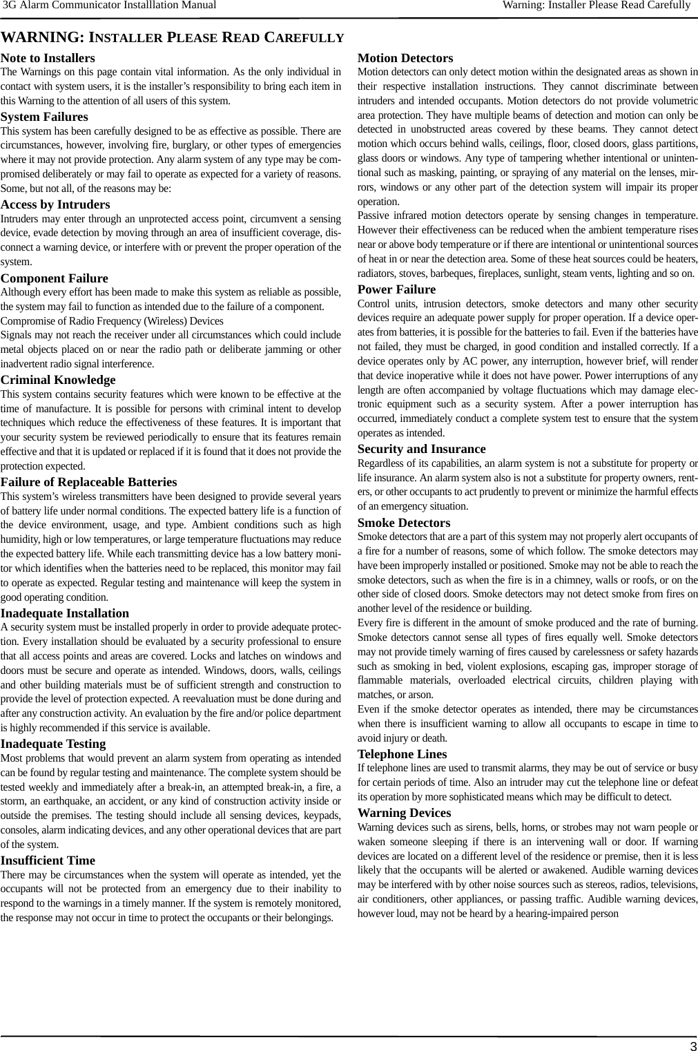
![IMPORTANT 3G Alarm Communicator Installlation Manual4IMPORTANTThis installation manual shall be used in conjunction with the Power Series Alarm Controller Power Panel manual. All the safety instructions specified withinthat manual shall be observed. (or equivalent). The Alarm Controller Power Panel is referenced as the “panel” throughout this document.The General Packet Radio Service (3G/GPRS)/Ethernet Communicator is a fixed, wall-mounted unit, located inside the panel, and shall be installed in thelocation specified in these instructions.The equipment enclosure must be fully assembled and closed, with all the necessary screws/tabs, and secured to a wallbefore operation. Internal wiring must be routed in a manner that prevents: • Excessive strain on wire and on terminal connections,• Interference between power limited and non power limited wiring,• Loosening of terminal connections, or• Damage of conductor insulation.WARNING: Never install this equipment during a lightning storm!Safety InformationThe Installer must instruct the System user on each of the following:• Do not attempt to service this product. Opening or removing covers may expose the user to dangerous voltages or other risks.• Any servicing shall be referred to trained service personnel only.• Use authorized accessories only with this equipment.• Do not stay close to the equipment during device operation. • Do not touch the external antenna.Model Information3G2060R: Is a 3G/GPRS Cellular alarm Communicator that sends alarm communication to Sur-Gard System I, II, III (SG-DRL3IP), and IV (SG-DRL4IP) cen-tral station receivers via a 3G/GPRS digital cellular network.TL260R: Is an Ethernet only alarm Communicator that sends alarm communication to Sur-Gard System I, II, III and IV central station receivers through awired Ethernet/Internet connection.TL2603GR: Is a Dual-path 3G/GPRS/Ethernet alarm Communicator that sends alarm communication to Sur-Gard System I, II, III, and IV central station receiversthrough Ethernet/Internet or a 3G/GPRS digital cellular network.The Communicator can be used as either a backup or primary Communicator. The Communicator supports Internet Protocol (IP) transmission of panel and Commu-nicator events over Ethernet/Internet and/or 3G/GPRS. The 3G/GPRS performance of the 3G2060R or TL2603GR Communicator depends greatly on 3G/GSM network coverage in the local area. The unit shouldnot be mounted in the final location without first performing the Communicator Placement Test below to determine the best location for radio reception (mini-mum of one green LED ON). Optional antenna kits are available from DSC at: http://www.DSC.com.NOTE: Prior to installation of the 3G2060R or TL2603GR Communicator, confirm with your local service provider that the 3G/GPRS network is available andactive in the area where the Communicator will be installed, and that radio signal strength (CSQ) is adequate.Panel MountingThe following Communicators are compatible with PC1616/PC1832/PC1864 panels:•3G2060R, 3G2060 (3G/GPRS only)•TL260R, TL260(Ethernet/Internet only)•TL2603GR, TL2303G (Ethernet/Internet + 3G/GPRS dual-path)NOTE: This manual covers Communicator models with and without ‘R’ throughout entire manual unless specifically states otherwise.Features• 128-bit AES encryption via 3G/GPRS and Ethernet/Internet (NIST Validation Certificate No. 1627).• Back up or primary 3G/GPRS alarm communication.• Ethernet LAN/WAN 10/100 BaseT (TL260R/TL2603GR only).• Full event reporting to central station (UL/ULC listed) and C24 Interactive, via RS-422 to the C24-HUB. (This supplementary feature is in addition to what is required for a UL/ULC Listed system configuration and it does not affect the required UL/ULC Listed signal-ing).• Fully redundant Ethernet/Internet and 3G/GPRS Dual-path Alarm Communication (TL2603GR only).• Individual Ethernet and/or 3G/GPRS Periodic test transmission.• Integrated call routing.• Remote Firmware upgrade capability of the Communicator and Panel Firmware via Ethernet and/or HSPA/3G radio.• Dual-Band Operation: 850 MHz, and 1900 MHz. (North America only).• Panel remote uploading/downloading support via 3G/GPRS and Ethernet/Internet.• PC-LINK connection.• Programmable Labels. • RS-422 balanced line for supplementary communication to the external C24-HUB up to 1,000 ft. (305 m) for C24 Interactive. (This supplementary feature is in addition to what is required for a UL/ULC Listed system configuration and it does not affect the required UL/ULC Listed signaling). Only models with “R”.• SIA and Contact ID (CID) formats supported.• Signal strength and Trouble display LEDs.• Subscriber Identity Module (SIM) card included with Communicator.• Supervision heartbeats sent via 3G/GPRS and Ethernet/Internet.• Supervision heartbeats via HSPA/3G/2G and/or Ethernet/Internet.• iControl ____________________________________________________________________________________ “TBDev_data_2B_provided_by_WH”Technical SpecificationsThe input voltage to the Communicator can be drawn from the Underwriters Laboratories/Underwriters Laboratories Canada (UL/ULC) Listed Control Panel orprovided by an external UL/ULC Listed power supply rated for the application (external power-limited source). NOTE: The power supply must be Class II, Power Limited.UL/ULC Installation RequirementsNOTE: For equipment used at the protected premises and intended to facilitate IP communications (hubs, routers, NIDs, Digital Subscriber Line (DSL), Cablemodems), 24 hour back-up power is required. Where such cannot be facilitated, a secondary (back-up) communication channel is required. Domain Name Service (DNS) programming is not permitted in UL/ULC listed systems.Notes for using Private, Corporate, and High Speed Data Networks:Network access and domain access policies shall be set to restrict unauthorized network access, and spoofing or Denial of Service (DoS) attacks. Select anInternet Service Provider (ISP) that has redundant servers/systems, back-up power, routers with firewalls enabled, and methods to identify and protect againstDoS attacks (e.g., via spoofing).Notes for using Public Switched and Cellular Data Networks:Communication channels shall be facilitated such that the Communicator will restrict unauthorized access, which could otherwise compromise security. TheCommunicator shall be located in a secured area.•For ULC Residential Fire and Burglary applications the TL2603GR can be used as primary communication channel via either 3G/GSM or Ethernet or as aback-up in conjunction with the Digital Alarm Communicator Transmitter (DACT). Test transmission every 24 hours shall be enabled on each channel.•For ULC Commercial Fire and Burglary applications the 3G2060R and TL2603GR can be used as a passive communication module with the followingSecurity Levels:• P1 (each channel 3G/GSM or Ethernet is independent), • P2 (3G/GSM and Ethernet in back-up configuration, Panel Section [851][005] Toggle Option [5] OFF).GENERAL](https://usermanual.wiki/Tyco-Safety-Canada/123G260R.USERS-MANUAL/User-Guide-1690419-Page-4.png)
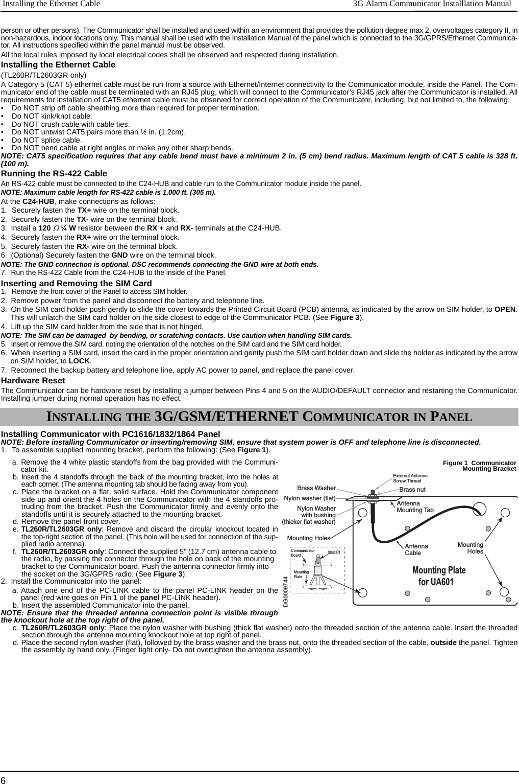
![3G Alarm Communicator Installlation Manual Ratings Compatibility5• P3 (3G/GSM and Ethernet in redundant configuration, Panel Section [851][005] Toggle Option [5] ON). • The Communicator can also be used as an Active communication system with the Security Levels A1-A4 (each channel 3G/GPRS or Ethernet indepen-dent or together in a back-up/redundant configuration). For Active Line Security systems AES128 bit encryption shall be enabled (at the monitoring stationreceiver) and the supervision heartbeat rate shall be set as 90 seconds (Panel Section [851][004] = 005A/90). The supervision window at the SignalReceiver Center (SRC)'s receiver shall be programmed as maximum of 180 (00B4/180) seconds.•For UL Residential Fire and Burglary applications the 3G2060R andTL2603GR can be used as the primary communication channel via either 3G/GSM orEthernet, or as a back-up in conjunction with the DACT (30 day test transmission is required on each channel). •For UL Commercial Burglary applications the TL2603GR can be used as Dual Signalling Line communication system (3G/GPRS and Ethernet channelsused in redundant configuration), Standard Line Security and as Encrypted Line Security. • The supervision heartbeat shall be enabled (Panel Section [851][005] Toggle Option [1] (Ethernet) and/or Toggle Option [2] (3G/GSM) shall be ON), Tog-gle Option [3] (Supervision Type) shall be ON and the supervision heartbeat rate shall be selected as 135 (0087/135) seconds. Option [004] = 0087. Thesupervision window at the supervising station shall be maximum 200 (00C8/200) seconds. For Encrypted Line Security systems the encryption AES128 bitshall be enabled at the monitoring station receiver.•For UL Commercial Burglary installations, the 3G2060R is listed as a primary (sole) communication means (heartbeat must be enabled) or for supplemen-tary (back-up) use in conjunction with a Plain Old Telephone Service (POTS) line dialer. When the heartbeat transmission over the Ethernet or 3G/GPRSnetwork is enabled, using the TL2603GR with a compatible control unit listed for standard/encrypted line security, it can provide line security for the alarmsystem over the primary line. • The TL2603GR is also suitable to be used with a compatible control unit listed for dual line security transmission when used in conjunction with a DACT ora Public Switched Data Network (PSDN) transmitter, where the PSDN provides the line security and is the primary line. In this mode, alarm signals arerequired to be sent simultaneously over both communication methods.Ratings CompatibilityNOTE: Enter [*][8][Installer Code][900] at keypad to view the Panel Version number.Products or components of products, which perform communications functions only shall comply with the requirements applicable to communications equip-ment as specified in UL60950 or CAN CSA C22.2. No. 60950-1, Information Technology Equipment - Safety - Part 1: General Requirements. Where networkinterfaces are internal to the control unit or receiver, compliance to CAN CSA C22.2. No. 60950-1 is adequate. Such components include, but are not limitedto: hubs; routers; NIDs; third-party communications service providers; DSL modems; and Cable modems.C24 InteractiveNOTE: This application has not been investigated by UL/ULC and is not be used on UL/ULC certified installations.The Communicator provides C24 Interactive monitoring and control via an RS-422 interface to an external C24-HUB. The default Keybus link speed is 115.2 KB and this option is programmable by the installer. All life-style events are transmitted by the RS-422 link to the C24-HUB and then remotely to the C24 Inter-active Servers.NOTE: The C24-HUB is an interface device which connects to security panels, IP cameras, sensors, Z-wave based home automation devices, etc. to deliver ahost of advanced functionality.NOTE: Life-style events are “non alarm” events. Life-safety events are “alarm” events.The following features are available with the RS-422 C24 Interactive:• Communicator faults can be transmitted. • Panel communication errors are reported to the C24-HUB.• Real time reporting of Zone status information to the C24 Interactive Server.• Remote update of the Communicator (flash upgrade).• SMS incoming “wake up” for the 3G/GPRS channel.• WEB login to request an incoming session with the Communicator.• Zone Label Programming. NOTE: Communicator buffers 1000 date/time stamped Life-Style events to the C24-HUB as First In First Out (FIFO). EncryptionThe Communicator uses 128 Bit AES Encryption. Encryption can only be enabled from the monitoring station receiver. Each receiver (Ethernet 1 and 2, 3G/GPRS 1 and 2) can independently have encryption enabled or disabled. When encryption is enabled, the central station will configure the device to encryptcommunications the next time the Communicator module performs a communication to that receiver. NOTE: Packets will start being encrypted only after the next event is sent to that receiver, or if the unit is restarted.Before leaving the installation site, the Communicator TL260R/TL2603GR Ethernet line shall be connected via an APPROVED (acceptable to the local authorities) Network Interface Device (NID) (e.g., for UL Installations, UL60950 listed NID). All wiring shall be performed according to the local electrical codes.This 3G/GPRS/Ethernet Communicator shall be installed by Service Persons only. (Service Person is defined as a person having the appropriate technical trainingand experience necessary to be aware of hazards to which that person may be exposed in performing a task and can also take measures to minimize the risks to thatTable 1: Communicator RatingsModel 3G2060R 3G/GPRS only TL260REthernet only TL2603GREthernet and 3G/GPRS POWER SUPPLY RATINGS• Input VoltageNominal 12 VDC: The panel Bell output shall be derated:700mA - (Communicator mA) = (derated Bell output). CURRENT CONSUMPTION• Standby Current90mA @ 13.66V 100mA @ 13.65V 120mA @ 13.66V• Alarm (Transmitting) Current400mA @ 12V• Operating FrequencyQuad band 850MHz, 900MHz, 1800MHz, 1900MHz• Typical Antenna Gain2dBiENVIRONMENTAL SPECIFICATIONS• Operating Temperature 32°F - 120°F (0°C - 49°C) • Humidity5% ~ 93% relative humidity, non-condensingMECHANICAL SPECIFICATIONS• Board Dimensions (mm)100 × 150 × 15 100 × 150 × 18 100 × 150 × 15 • Weight (grams) with bracket310 290 320 Table 2: Compatible Receivers, and PanelsCommunicator Receiver/Panel Description3G2060RTL260RTL2603GRReceiver• Sur-Gard System I Receiver, version 1.13+• Sur-Gard System II Receiver, version 2.10+• Sur-Gard SG-DRL3-IP, version 2.30+ (for Sur-Gard System III Receiver)• Sur-Gard SG-DRL4-IP version 1.20+ (for Sur-Gard System IV Receiver)Panel• Power Series PC1616, version 4.5+• Power Series PC1832, version 4.5+• Power Series PC1864, version 4.5+PRE INSTALLATION CONFIGURATIONCOMMUNICATOR INSTALLATION CONFIGURATION](https://usermanual.wiki/Tyco-Safety-Canada/123G260R.USERS-MANUAL/User-Guide-1690419-Page-5.png)
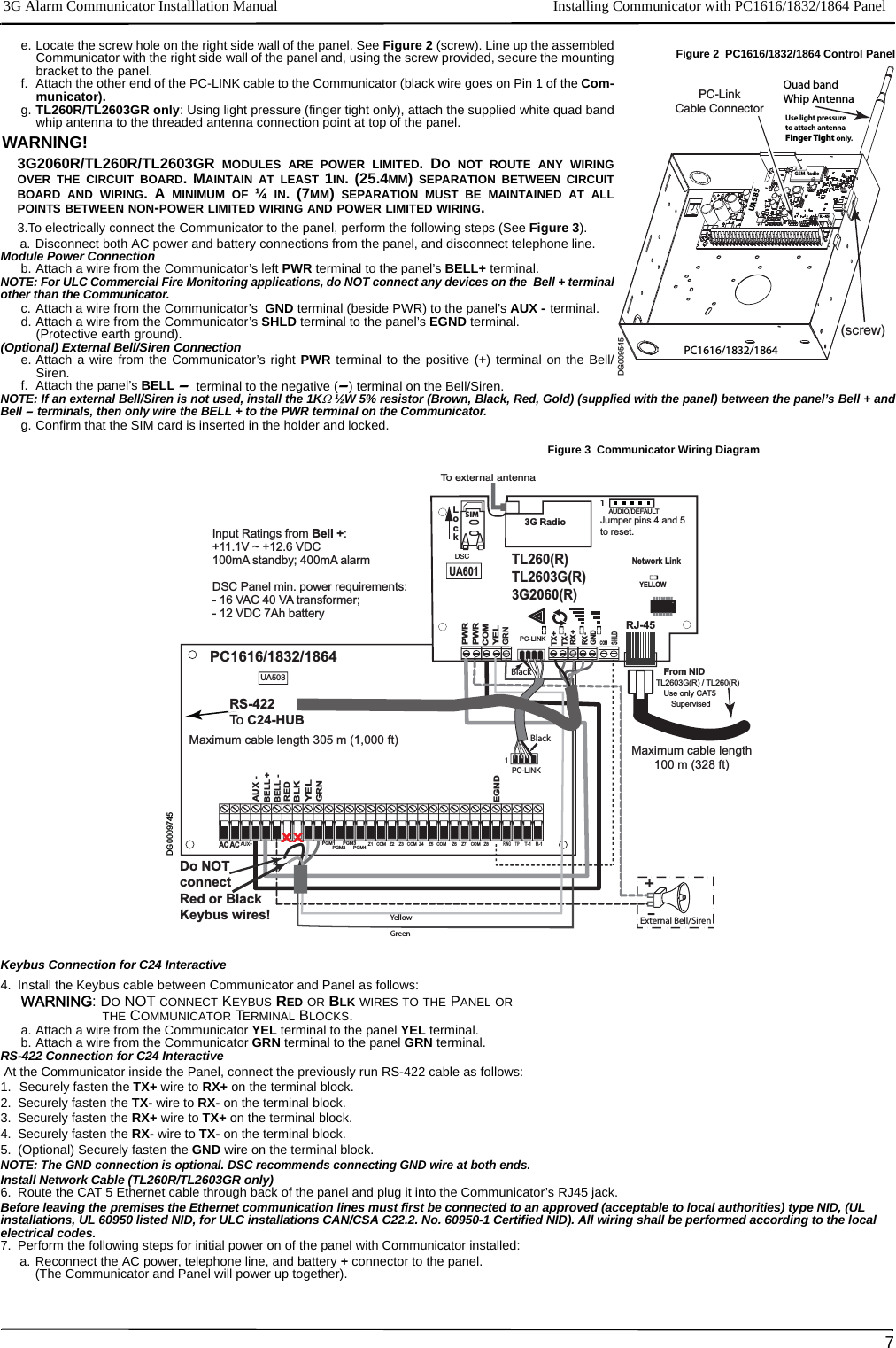
![Keypad Data Display 3G Alarm Communicator Installlation Manual8b. Observe that the Communicator’s red and yellow LEDs are flashing together while it initializes. The red and yellow LEDs will continue to flash until theCommunicator has successfully communicated to all programmed receivers. If this is the first time the Communicator has been powered up in the panel,the module will initiate communication to Connect24 to request remote programming.NOTE: Initialization may take several minutes to complete. red and yellow LEDs will flash together during initialization. Do not continue to next step until the redand yellow LEDs have stopped flashing. (If only the yellow LED is flashing, there is a Communicator trouble and the Green LEDs are not valid for CommunicatorPlacement Test). Correct trouble indicated by flashes on yellow LED before continuing. (See Table 5 for troubleshooting assistance).8. 3G2060R/TL2603GR only: Perform the Communicator Placement Test below.9. Mount the Panel in final location indicated by placement test. Domain Name Service (DNS) programming is not permitted in UL/ULC listed systems.Keypad Data DisplayNOTE: Programming locations accessible via the keypad are for viewing only. All communicator programming is modified via Connect24.•Section-Toggle Options: The number is displayed when Toggle is ON, the number is not displayed when Toggle is OFF. (e.g., Toggle Options displays: [--3--6--]. Options 3 and 6 are ON, all others are OFF). Pressing keys 1 through 8 will alternately turn the Toggle ON and OFF.•HEX/Decimal Data: Values that are provided with two defaults, separated by a “/” character, use the format: hexadecimal followed by decimal equivalent(e.g., Default [0BF5/3061]). Hexadecimal numbers are shown, with all leading zeroes, to the full field length defined for the number.Entering HEX values at keypadTo enter HEX values at the keypad, you must press the * key before entering the HEX value. (e.g., to enter “C” at the keypad, press [*][3]. Entering ASCII Characters at keypad1. Press [*] and use scroll buttons [<] [>] to display “ASCII Entry” on the LCD screen. 2. Press [*] to select ASCII entry mode. 3. Use the [<] [>] scroll keys to display the character you want and press [*] to save and exit ASCII. 4. Repeat the steps above to enter another ASCII character.PC1616/1832/1864 Initial ProgrammingPerform the following steps to ensure that the Communicator and the Panel work together as intended.These Sections must be programmed at the panel keypad. Enter [*][8][Installer Code][Section Number]. Record any values that are modified from their default,in the appropriate Worksheets for the Panel or Communicator. 1. In Panel Section [167] program 060 (seconds).2. In Panel Section [382] set Option [5] ONNOTE: If this option is OFF, the yellow status LED on the Communicator will indicate ‘Panel Supervision Trouble’ (2 flashes) and the unit can not be programmed via thePC-LINK cable.3. In Panel Section [383] set Option [7] ON.4. In Panel Section [383] set Option [8] ON for CID, or OFF for SIA.5. A valid Account Number must be entered in Communicator Section [851][021]. See Programming Section.NOTE: DSC recommends using the same Account Number for Panel and Communicator.6. In Panel Sections [301], [302], and [303], program the central station telephone number that will be used for the 3G/GPRS/Ethernet Communicator. Validentries are:a. A valid telephone number; signals will be routed to the central station using the PSTN. b. DCAA (Receiver 0); signals will be routed to 3G/GPRS/Ethernet Receivers 1 - 4 depending on programming Toggle Options in Communicator Section[851][006].c. Panel Section [301] sets the Primary communication path, and may be configured as either PSTN or Communicator routing. Panel Section [302] isredundant, and Panel Section [303] is the backup telephone number for Panel Section [301]. Refer to the Panel manual for additional information.NOTE: The leading digit ‘D’ (dial tone detection) in the telephone number is pre-programmed.7. In Panel Section [350], program the communication format as: CID (03) or SIA FSK (04). NOTE: If any of the Panel telephone numbers have been set to DCAA, section [350] must be set to (04).8. In Panel Sections [351] - [376], program the Communicator call direction options. Refer to the Panel Installation Manual for details on setting these options.9. In Panel Section [401] set Toggle Option [2] ‘User Enable DLS’ to ON in order to perform panel DLS session through 3G/GPRS or Ethernet.NOTE: Before leaving the premises, the installer should verify all programmed communications paths. See Programming Options Section[851][901] to send immediate test transmissions.Communicator Troubles displayed on a PC1616/1832/1864The General System trouble is the only trouble that will appear on the keypad Liquid Crystal Display (LCD) when encountered by a Communicator installed ina PC1616/1832/1864. For more information about the trouble on the Communicator module refer to the panel event buffer. Log entry will show Fault orRestore for each of the following events:•T-LINK Network Fault/Restore: This log will occur for the following trouble conditions: SIM Lock Trouble, 3G/GSM Trouble, Ethernet Trouble, orConnect24 Configuration Trouble.•T-LINK Receiver Trouble/Restore: This log will occur for the following trouble conditions: Receiver Not Available Trouble, Receiver Supervision Trouble,or Failure to Communicate (FTC) Trouble.•T-LINK Comm. Fault/Restore: This log will occur when the panel loses communications with the Communicator and will clear when communications isrestored. (3G2060R and TL2603GR only).To confirm that the 3G/GPRS antenna location is suitable for radio operation, perform the placement test as follows: NOTE: You may need to relocate the Panel or install an optional extension antenna during this procedure, if radio signal strength is too low.1. Confirm that the yellow LED on the Communicator is not flashing. A flashing yellow LED indicates trouble on the Communicator. See Table 5 to trouble-shoot and correct the cause of this trouble before continuing to the next step.2. Observe the strength of the radio signal on the yellow LED and the 2 green LEDs on the Communicator meet or exceed the minimum signal level requirement.Minimum Signal Level: The yellow LED is OFF and the Green LED 1 (furthest from the yellow LED) is ON. (i.e., not flashing) for the panel location to be accept-able. See table for “Radio Signal Strength” on page 9 for interpretation of receiver signal strength on LEDs.NOTE: If the required signal strength is too low with the panel in its current location, the panel must be relocated or an external antenna isrequired. a. If required, the following 3G/GSM extension antenna kits are available to the installer: •GS15-ANTQ - 4.57m (15’)Internal Antenna Extension Kit (Suitable for interior mounting only).•GS25-ANTQ - 7.62m (25’)External Antenna Extension Kit (Suitable for exterior mounting only).•GS50-ANTQ - 15.24m (50’)External Antenna Extension Kit (Suitable for exterior mounting only).Specific instructions for the installation of the extension antenna are included with the kit. Observe all the electrical safety instructions regarding the installation of the antenna. All the wiring of the equipment shall be fully compliant with the local rules and regulations.3. If required, install the antenna extension and perform the following steps to determine the best location for placement of the antenna : a. Disconnect the white whip antenna from the panel.b. Attach one end of the antenna extension cable to the threaded antenna connector on the panel and the other end to the external antenna.4. Move the extension antenna to various locations while observing the two Green LEDs on the panel. a. Continue to reposition the extension antenna until you receive an acceptable (minimum one green LED ON solid) signal strength.NOTE: Minimum strength is: green LED 1 flashing and yellow LED OFF. If green LED 1 is flashing, relocation should be considered.b. Mount the supplied antenna extension bracket at the location that provides the best signal strength.INITIAL PANEL PROGRAMMINGCOMMUNICATOR PLACEMENT TEST](https://usermanual.wiki/Tyco-Safety-Canada/123G260R.USERS-MANUAL/User-Guide-1690419-Page-8.png)
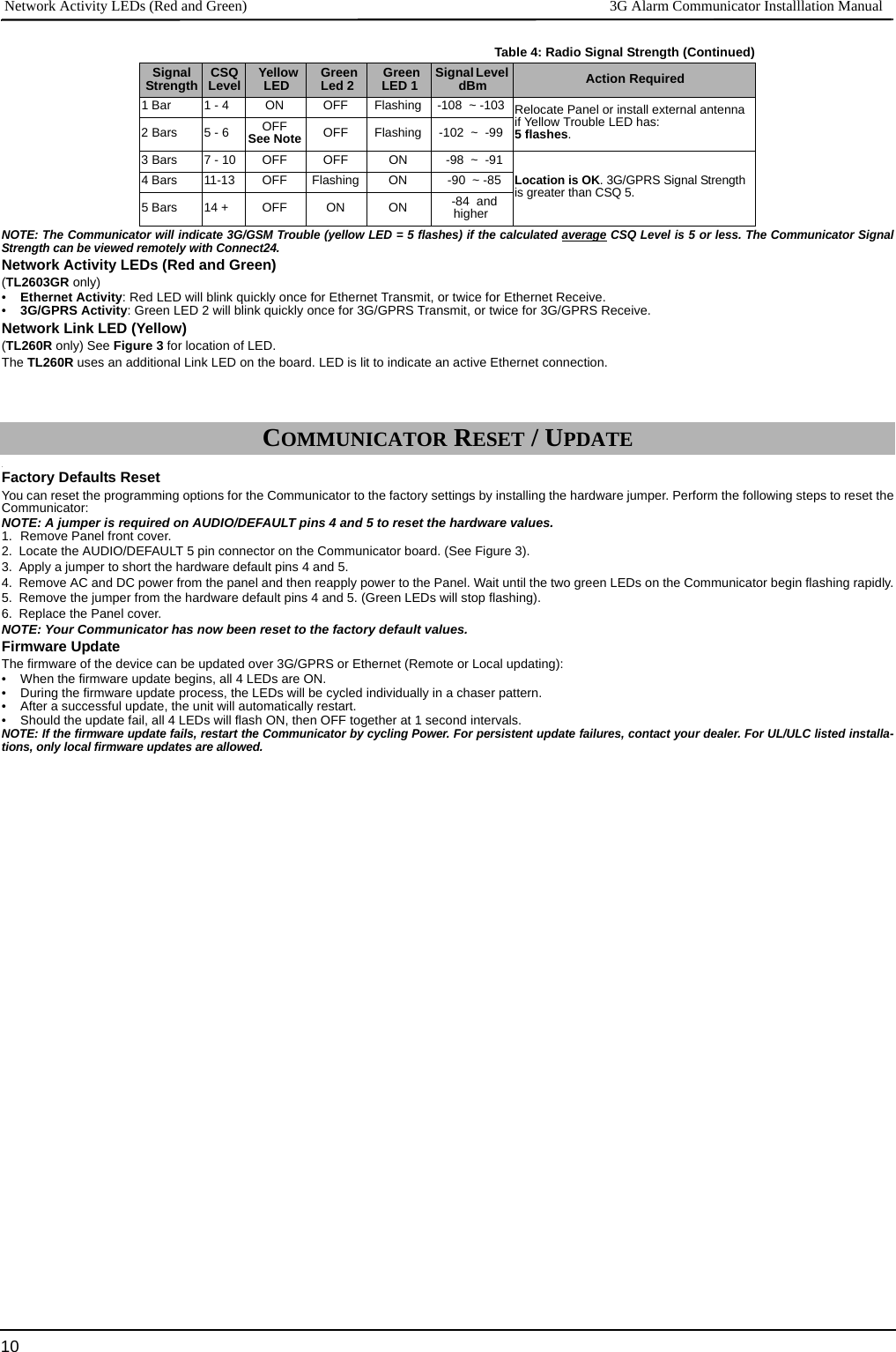
![3G Alarm Communicator Installlation Manual Yellow Trouble LED95. Alternately, you can reposition the Panel to improve signal strength. Dismount the panel and move it to another location to achieve the required signalstrength. If the Panel is relocated to improve signal strength, mount it in the new location.6. When final Panel/antenna location is determined, continue at the Initial Panel Programmingsection.The Communicator has 4 onboard LED indicators. These include 1 yellow trouble LED, 1 red Network Connection Status LED, and 2 green Signal StrengthLEDs. The LED meaning is described in this Section.Yellow Trouble LEDThis yellow LED will flash to indicate a trouble on the unit. The number of flashes indicates the type of trouble. See the table below for the coded flashes andthe conditions which will activate the Trouble Status LED.NOTE: Only the highest priority trouble (2 Flashes is the highest priority trouble) is indicated. When this trouble is restored, the next highest trouble will indi-cate, if present. This will continue until all troubles have been cleared. (yellow LED is not flashing).The following paragraphs describe the conditions associated with the trouble indicated:Panel Supervision Trouble (2 Flashes)This trouble will be indicated when communication between the Communicator module and the Panel fails. If the module can not communicate with the Panel(e.g., loss of power to the panel) the Communicator will send the ‘Panel Absent Trouble Event’ message to the central station receiver. When communicationreturns, a ‘Panel Absent Restore Event’ is sent by the Communicator to the central station receiver. The reporting codes are ET0001 for Trouble and ER0001for Restore. The panel absent event always uses the primary receiver account code when communicating to the central station. NOTE: The Panel Supervision Trouble/Restore are internally generated events by the Communicator. They are the only internal events; all other events are gen-erated by the panel. Trouble is generated if the Communicator misses 6 Polls. Trouble is restored on receipt of first Poll from the Panel.SIM Lock Trouble (4 Flashes)This trouble will signify that the SIM lock feature has been enabled and the unit has not been programmed with the correct PIN for the SIM card.3G/GSM Trouble (5 Flashes)This trouble is indicated for any of the following 4 conditions: 1. Radio Failure: Trouble is indicated after 8 failed attempts to communicate with the 3G/GPRS radio.2. SIM Failure: Trouble is indicated after 10 failed attempts to communicate with the SIM. 3. 3G/GPRS Network Trouble: Trouble is indicated for loss of the registration to the network provider.4.Insufficient Signal Strength: Trouble is indicated if calculated average signal strength is too low. (Both green LEDs are OFF). Trouble will clear when the calcu-lated average signal strength is above minimum (i.e., > CSQ 5).Ethernet Trouble (6 Flashes)This trouble is indicated when Ethernet link between the transmitter and the local switch or router is absent. This trouble will also be indicated if the unit fails toget Dynamic Host Control Protocol (DHCP) settings from the DHCP server. (Not active if Ethernet Receivers are not programmed).Receiver Not Available (7 Flashes)This trouble is indicated if the unit is not able to successfully initialize with any of the programmed receivers. Unprogrammed receivers are excluded. This trou-ble is also indicated if the 3G/GPRS receiver APNs have not been programmed in Sections [205] and [215].Receiver Supervision Trouble (8 Flashes)This trouble is indicated when receiver supervision is enabled and communication between the Communicator module and the receiver fails. Trouble is indi-cated if Ethernet 1 is supervised and does not receive a heartbeat from the receiver or if 3G/GPRS is supervised and the unit does not receive an acknowledg-ment to 4 heartbeats sent to the receiver.FTC Trouble (9 Flashes)This trouble is indicated when the unit fails to communicate module events to the central station. Trouble is displayed after the unit has exhausted all commu-nications attempts to all programmed receivers for events generated by the Communicator.Configuration Failure (10 Flashes)This trouble is indicated when the unit fails to receive remote programming.Remote Programming (11 Flashes)This trouble is indicated during a remote firmware upgrade. Indicates that a remote firmware update is in progress over 3G/GPRS/Ethernet. Trouble will clearautomatically when update completes successfully.Module Configuration Trouble (12 Flashes)This trouble is indicated when the System Account Code or the Receiver Account have not been programmed. Disabled receivers are excluded. Red Network Connection Status LED (TL260R/TL2603GR)BLINKING: Indicates communications in progress.• Once quickly for outgoing Ethernet transmission.• Twice quickly to indicate incoming Ethernet ACK/NACK.OFF: This is the normal state of the Red Network Connection Status LED. There are no network connection issues present. ON: There is a problem with the Ethernet or the 3G/GPRS network connection. LED will be ON if any of the following occur:• Ethernet cable is not connected,• DHCP configuration times out,• Unit fails to get an IP address from the 3G/GPRS network, or• 3G/GPRS connection has been reset. (Green LED 1) (Green LED 2) and (Yellow LED) Signal Strength NOTE: If the yellow LED is flashing, Signal Strength in table below is not valid. See Table 5 for troubleshooting flashing yellow LED.COMMUNICATOR STATUS LEDSTable 3: Yellow Trouble Status LED# of Flashes Trouble # of Flashes Trouble2 Panel Supervision Trouble 8 Receiver Supervision Trouble4 SIM Lock Trouble 9 FTC Trouble5 3G/GSM Trouble 10 Configuration Failure6 Ethernet Trouble 11 Remote Programming7 Receiver Not Available Trouble 12 Module Configuration TroubleTable 4: Radio Signal StrengthSignal Strength CSQ Level Yellow LED Green Led 2 Green LED 1 Signal Level dBm Action RequiredNo Signal 0 ON OFF OFF -108.8 • Check all antenna connections. • Confirm 3G/GPRS service is active in area. • Relocate Panel or install external antenna.](https://usermanual.wiki/Tyco-Safety-Canada/123G260R.USERS-MANUAL/User-Guide-1690419-Page-9.png)
![3G Alarm Communicator Installlation Manual Firmware Update11_____________________________________________________________________________________________________________________________________________________________________________________________________________________________________________________________APPENDIX A: COMMUNICATOR TROUBLESHOOTINGTable 5: Trouble LED indicationsTrouble indication Possible Causes Trouble Possible SolutionNo Indication No Power• Check the power connections between the Panel and the Communicator.• Confirm PC-LINK cable is properly installed between communicator and panel.Yellow LED – ON Solid Insufficient Signal Strength• Confirm that 3G/GPRS network service is active in your area.• Ensure the antenna is securely connected to the radio. Check antenna stub cable issecurely connected to the radio.• If an external antenna is used ensure the antenna is securely screwed on to the antennacable connector. Check external antenna for damage or open/short.Trouble LED – 2 FlashesPanel Supervision Trouble• Check Section [382]Toggle Option[5] is ON.(3G/GPRS/Ethernet Module Enabled)• Ensure the PC-LINK cable between the Panel and Communicator is connected properly(not reversed) and is securely in place.Yellow LED - 4 Flashes Lockout Trouble• The SIM card has incorrect PIN programmed or has a PIN that the module does not rec-ognize. Replace the SIM card.Yellow LED – 5 Flashes 3G/GSM Trou-ble• Confirm that 3G/GPRS service is available and active in your area. • Check all antenna connections. • Ensure average radio signal strength is CSQ 6 or higher. (See Table 4 ).• Ensure the SIM card is properly inserted into the SIM card holder.• Ensure the SIM card has been activated. (Could take up to 24 hrs after install).• If this trouble persists, you must relocate the Panel (and Communicator) or install anexternal antenna extension kit.Yellow LED – 6 Flashes Ethernet Trouble• Check with your ISP to confirm Internet service is active in your area.• Ensure your Ethernet cable is securely inserted into the RJ45 jack of the Communicatorand the Hub/Router/ Switch.• Check the link light on the Hub/Router/ Switch is ON . If link light is OFF, try restarting theHub/Router/ Switch. • If DHCP is used, ensure that the unit has an assigned IP address from the server. InSection [851] [992] verify a valid IP address is programmed. If not, contact the Networkadministrator.• If problem persists, replace the Ethernet cable and RJ45 connector.Yellow LED – 7 Flashes Receiver Not Available• Ensure that the Ethernet path has internet connectivity.• If you are using a static IP address make sure the gateway and subnet mask are enteredcorrectly.• If the network has a firewall, ensure the network has the programmed outgoing ports open (Default UDP Port 3060 and Port 3065).• Ensure that all the receivers are programmed for DHCP or have the proper IP addressand port number.• Ensure the 3G/GPRS Receiver APNs have been programmed with the Access PointName provided by your 3G/GPRS provider.Yellow LED – 8 FlashesReceiver Supervision Trouble• This trouble is indicated when supervision is enabled and the unit is not able to success-fully communicate with the receiver.• If this trouble persists, contact your central station.Yellow LED - 9 Flashes FTC Trouble• The unit has exhausted all communications attempts to all programmed receiver forevents generated by the Communicator.• Restart the system, if trouble persists, contact your dealer.Yellow LED – 10 FlashesConnect24 Configuration Failure• The SIM is active but there is no programming for the Communicator.• Ensure a profile has been programmed in Connect 24 for the SIM.• You can confirm your programming by calling the Connect 24 VRU, or by logging intothe Connect24 VRU web site.Yellow LED – 11 Flashes Remote Programming• The LEDs will flash when a remote firmware upgrade is in progress over Ethernet or 3G/GPRS. The LEDs will extinguish when update is complete.• The LEDs will flash to indicate a remote programming session is active over Ethernet or3G/GPRS. The LEDs will extinguish when the session terminates.Yellow LED – 12 FlashesModule Configuration Trouble• This indication appears when Section [021] System Account Code or Section [101]; [111]; [201]; and [211] Receiver Account Code have not been pro-grammed. Ensure that a valid account code has been entered in these Sections.All LEDs flash-ing together Boot Loader Failed• Disconnect power, then reconnect power to the Communicator module. Red and Yellow LEDs flashing togetherInitialization Sequence• The unit is still initializing please wait while the unit gets its programming and establishesa connection to all programmed receivers. Note: This process may take several minutes to complete.Only Green LEDs flashing Hardware Default Jumper• The hardware default jumper is installed and must be removed. See Figure 3.](https://usermanual.wiki/Tyco-Safety-Canada/123G260R.USERS-MANUAL/User-Guide-1690419-Page-11.png)
![System Options 3G Alarm Communicator Installlation Manual12The Programming Sections described in this document can be viewed at the SCW LCD. To start programming enter: [*][8][installercode] [851][# # # ], Where ### is the 3 digit Section number referenced in this section. The Programming Worksheets at the end ofthis document can be used to record the new values when programming changes have been made from the default values.Programming Sections are accessed through Connect24. Installers may review/record programming Options at the panel.NOTE: Ethernet/Cellular Programming Sections accessed through the panel are for display purposes only. Configuration changes must be done using Connect24.SYSTEM OPTIONS[001] Ethernet IP AddressDefault (000.000.000.000)Enter the IP address of the Communicator. Ensure that the IP address is unique to your Communicator on the local network. Format is 4fields, each field is a 3 digit decimal number. Valid range: 000-255. If an IP address is programmed in this Section, the unit will operatewith Static IP (DHCP disabled). Sections [002] and [003] must also be programmed when using Static IP addresses.NOTE: Default for this Section is Dynamic Host Configuration Protocol (DHCP) enabled. When enabled, the DHCP Server will setvalues for: IP Address [001], Subnet Mask [002], and Gateway [003]. Programming an IP address in this Section will disableDHCP (Static IP).[002] Ethernet IP Subnet MaskDefault (255.255.255.000)Enter the Ethernet IP Subnet Mask of the Communicator. Format is 4 fields, each field is 3 digits. Valid range: 000-255.NOTE: If DHCP is enabled, the DHCP Server will assign the subnet mask for this Section and the programmed value will be ignored.[003] Ethernet Gateway IP AddressDefault (000.000.000.000)Enter the Ethernet Gateway IP address of the Communicator. The gateway IP address is required when a router is used on the local net-work to reach the destination IP address specified in Section [001]. Format is 4 fields, each field is a 3 digit decimal number. Validrange: 000-255.NOTE: If DHCP is enabled, the DHCP Server will assign the Gateway IP address for this Section and the programmed value will beignored.[004] Receiver Supervision IntervalDefault (0087/135)When receiver supervision is enabled (ON) in Section [005] Toggle Option [3], the unit sends heartbeats to Ethernet Receiver 1 or Cel-lular Receiver 1 to test the communications path. Use this Section to set the interval time (in seconds) when heartbeats will be sent tothe receivers. Valid range 000A-FFFF seconds. If the programmed value is less than (000A/10) seconds, supervision is disabled.•Receiver Window: This is the supervision timeout that must be configured at the central station receiver.•Recommended Values: This is the recommended heartbeat interval that should be programmed into the Communicator.• For ULC installations, the Daily test transmission must be enabled over each available communication channel Sections [125] and[225]. When programming with Connect24, the recommended intervals will be programmed automatically when the required win-dow is selected.[005] System Toggle Options[1] Ethernet Receiver 1 SupervisedDefault (OFF)(TL2603GR/TL260R only).ON: Ethernet Receiver 1 will be supervised and heartbeats will be sent to Ethernet Receiver 1 based on the supervision interval pro-grammed in Section [004].OFF: Ethernet Receiver 1 will not be supervised. When disabled, heartbeat 1 is sent to the Ethernet receiver once every hour, regardlessof supervision type (heartbeat 1 or 2). The heartbeat is resent every 5 seconds until ACK. If no event or heartbeat ACK is received after(Receiver Supervision Interval + 75 seconds), Supervisory trouble is indicated.NOTE: Ethernet Receiver 2 can not be supervised.[2] Cellular Receiver 1 SupervisedDefault (OFF)ON: Cellular Receiver 1 will be supervised and heartbeats will be sent to Cellular Receiver 1 based on the supervision interval pro-grammed in Section [004]. If ACK to heartbeat is not received, it is retransmitted every 5 seconds. Failure to ACK 2 consecutive heart-beats will reset the radio.OFF: Cellular Receiver 1 will not be supervised. When disabled, heartbeat is not sent to the receiver. Supervisory trouble is indicated.NOTE: Cellular Receiver 2 can not be supervised.[3] Supervision TypeDefault (OFF)ON: Heartbeat 1 (Commercial Supervision). This supervision type is suitable for applications where swap detection is required on thesupervisory packet.OFF: Heartbeat 2 (Residential Supervision). This supervision type is suitable for applications where supervision of the communicationpath to the receiver is required. (no swap detection).ETHERNET/CELLULAR PROGRAMMING OPTIONS](https://usermanual.wiki/Tyco-Safety-Canada/123G260R.USERS-MANUAL/User-Guide-1690419-Page-12.png)
![3G Alarm Communicator Installlation Manual System Options13NOTE: Commercial supervision is more data intensive than residential supervision and should only be used when required to meet the approval for the installation.[4] Primary PathDefault (OFF - TL2603GR/TL260R) (ON - 3G2060R)ON: Cellular channel is the primary path. Ethernet channel is the secondary path, if it exists.OFF: Ethernet channel is the primary path in a dual Communicator. Cellular channel is the secondary path.[5] Redundant Communications Default (OFF) (TL260R only)ON: Events will be communicated to Ethernet Receiver 1 and Cellular Receiver 1 at the same time. Events will be communicated toEthernet Receiver 2 and Cellular Receiver 2 at the same time. As long as the event is successfully communicated to 1 of the 2 paths(Ethernet or Cellular) the Communicator will move on to the next event.NOTE: Do not configure Ethernet Receiver 1 and Cellular Receiver 1 to communicate using a common receiver configuration (i.e., identical Receiver IP address and Receiver Remote Port). OFF: Events will be communicated to the receivers individually.Toggle should be OFF when guaranteed message delivery to both receivers is required. [6] Remote Firmware UpgradeDefault (ON)ON: The Communicator module firmware can be remotely upgraded using the Ethernet/Cellular paths.OFF: The Communicator module firmware can not be remotely upgraded. Local firmware upgrade is still possible.[7] Alternate Test TransmissionsDefault (OFF).ON: When the periodic test transmission interval occurs, the test transmission will alternate between being sent to the primary and sec-ondary receivers with each test transmission interval.OFF: When the periodic test transmission interval occurs, the test transmission will be sent to the programmed receivers, based on thesettings of the periodic test transmission reporting codes.[8] Cellular Low Signal Trouble.Default (OFF)This option masks the Low Signal trouble from the Cellular trouble event.ON: A Cellular Trouble event is transmitted to receiver when the radio signal level falls below threshold level (average CSQ level is 4or less).OFF: A Cellular Trouble event is not transmitted to receiver when the radio signal level falls below threshold level (average CSQ levelis 4 or less).[006] System Toggle Options 2[1] Ethernet 1 Receiver Enabled.Default (ON) (OFF for 3G2060R).ON: Ethernet Receiver 1 is enabled.OFF: Ethernet Receiver 1 is disabled.[2] Ethernet 2 Receiver Enabled.Default (ON) (OFF for 3G2060R).ON: Ethernet Receiver 2 is enabled.OFF: Ethernet Receiver 2 is disabled.[3] Reserved. ( ).[4] Cellular 1 Receiver Enabled.Default (ON).(OFF for TL2603GR)ON: Cellular Receiver 1 is enabled. OFF: Cellular Receiver 1 is disabled.[5] Cellular 2 Receiver Enabled.Default (ON).(OFF for TL2603GR)ON: Cellular Receiver 2 is enabled.OFF: Cellular Receiver 2 is disabled.[6] Reserved ( ).[7] DLS Over Cellular.Default (ON).NOTE: Program this toggle as OFF if you want to completely disable DLS from using the Cellular path.ON: DLS is enabled on the Cellular path.OFF: DLS is disabled on the Cellular path.NOTE: If this Toggle is OFF, DLS sessions will occur on the Ethernet path only, regardless of Primary Path set in Section [005] Toggle Option [4]. If it is ON then the Communicator will connect to the Primary path first for DLS and if the session fails, the Sec-ondary path will be used.[8] Reserved ( ).[007] DNS Server IP 1Default (000.000.000.000)Programming this Section is not permitted on a UL/ULC listed system.](https://usermanual.wiki/Tyco-Safety-Canada/123G260R.USERS-MANUAL/User-Guide-1690419-Page-13.png)
![Programming Options 3G Alarm Communicator Installlation Manual14Enter the IP address for DNS Server 1. Format is 4 fields, each field is a 3 digit decimal. Valid range: 000-255.NOTE: If no value is programmed and DHCP is used, the DHCP Server will configure the address. If an address is programmed and DHCP is used, the address that you program will be used instead of the DHCP address.[008] DNS Server IP 2Programming this Section is not permitted on a UL/ULC listed system.Default (000.000.000.000)Enter the IP address for DNS Server 2. Format is 4 fields, each field is a 3 digit decimal. Valid range: 000-255.NOTE: If no value is programmed and DHCP is used, the DHCP Server will assign this value. If an address is programmed and DHCP is used, the address that you program will be used instead of the DHCP address.PROGRAMMING OPTIONS[010] System Toggle OptionDefault (Disable)[1] This bit is used to enable/disable two way audio over 3G.[011] Installer CodeDefault (CAFE)Program your installer code for this Communicator module. The installer code will be required when programming the Communicatormodule. Valid range: 0000 - FFFF.[012] DLS Incoming PortDefault (0BF6/3062)The DLS Incoming Local Port (listening port) is the port DLS IV will use when connecting to the Communicator. If a router or gatewayis used, it must be programmed with a Transmission Control Protocol (TCP) port forward for this port to the Communicator module IPaddress. Valid range: 0000 - FFFF.[013] DLS Outgoing PortDefault (0BFA/3066)The DLS Outgoing Port is used for outgoing session to DLS IV after an SMS request has been sent to the Communicator. Use this Sec-tion to set the value of the local outgoing port. The value must be changed if the Communicator is located behind a firewall and must beassigned a particular port number, as determined by your network administrator. In most cases, changing the default value or configur-ing your firewall with this port is not required. Valid range: 0000-FFFF.NOTE: If Section [006] Toggle Option [7] is ON, DLS will use the Primary path for session. If Section [006] Toggle Option [7] is OFFDLS will use the Ethernet path, if available.[021] Account CodeDefault (FFFFFF)The account code is included when transmitting any events generated by the Communicator. (e.g., Panel Absent Trouble). It is recom-mended that the account code be the same as the control panel account number. Valid range: 000001-FFFFFE. If 4 digit account codesare needed the 2 lowest digits shall be programmed as FF.(e.g., Account 1234 is programmed as:1234FF).NOTE: Programming this Section with all 0 or F will cause a Module Configuration Trouble.[022] Communications FormatDefault (04)Program 03 for Contact ID (CID). Program 04 for SIA. The module can be configured to send Events in SIA or CID format. The SIAcommunication format follows the level 2 specifications of the SIA Digital Communication Standard - October 1997. This format willsend the account code along with its data transmission. The transmission will look similar to the following at the receiver. Example:Nri0 ET001Where: N = New Event; ri0 = Partition/Area identifier; ET = Panel Absent Trouble; 001 = Zone 001.COMMUNICATIONS REPORTING CODES[023] Panel Absent TroubleDefault (FF)Program 00 to disable this event or FF to enable. This event will occur when communications with the panel have been lost for morethan 60 seconds.Table 6: Communications Reporting CodesEvent SIA IdentifierSIA Reporting CodeCIDQualifierCID Event CodeCID Reporting CodeCID User/Zone[023] Panel Absent Trouble ET 001 1 3 55 001[024] Panel Absent Trouble Restore ER 001 3 3 55 001[025] Radio Activation Restore RS 001 3 5 52 001[026] Ethernet 1 Test Transmission RP 001 1 6 A3 951[027] Ethernet 2 Test Transmission RP 002 1 6 A3 952[028] Cellular 1 Test Transmission RP 003 1 6 A3 955[029] Cellular 2 Test Transmission RP 004 1 6 A3 956[030] FTC Restore YK 001 3 3 54 001](https://usermanual.wiki/Tyco-Safety-Canada/123G260R.USERS-MANUAL/User-Guide-1690419-Page-14.png)
![3G Alarm Communicator Installlation Manual System Test Options [026 - 029]15[024] Panel Absent Trouble RestoreDefault (FF)Program 00 to disable this event or FF to enable. This event will occur when communications with the control panel have resumed.[025] Radio Activation RestoreDefault (FF)Program 00 to disable this event or FF to enable. This event will occur after any successful Connect24 programming session.SYSTEM TEST OPTIONS [026 - 029]Test Transmissions to Primary Receiver, with Backup to Secondary Receiver:Set Ethernet Section [026] to (FF); [027] to (00). Set Cellular Section [028] to (FF); [029] to (00).• If the test transmission fails to the primary receiver it will backup to the secondary receiver.• If the test transmission fails to the secondary receiver an FTC trouble will be generated.Test Transmission Unique to Primary and Secondary Receivers:Set Ethernet Section [026] to (FF); [027] to (FF). Set Cellular Section [028] to (FF); [029] to (FF).• The module will send periodic test transmissions to each receiver independently, with no backups.• If the test transmission fails to any of the programmed receivers, an FTC trouble will be generated.Alternate Test Transmission:Alternate Test Transmission can be enabled or disabled in Section [005] Toggle Option [7].[026] Ethernet 1 TransmissionDefault (FF)Program 00 to disable this event transmission or FF to enable. See System Test Options (above) for details on settings.[027] Ethernet 2 TransmissionDefault (00)Program 00 to disable this event transmission or FF to enable. See System Test Options (above) for details on settings.[028] Cellular 1 TransmissionDefault (FF)Program 00 to disable this event transmission or FF to enable. See System Test Options (above) for details on settings.[029] Cellular 2 TransmissionDefault (00)Program 00 to disable this event transmission or FF to enable. See System Test Options (above) for details on settings.NOTE: The time interval (in minutes) between periodic tests is programmed in Section [125] (Ethernet) and Section [225] (Cellular).[030] FTC RestoreDefault (FF)Program 00 to disable this event transmission or FF to enable. This event will occur when an FTC Trouble on the system restores.[033] Communicator Firmware Update BeginDefault (FF);Program 00 to disable this event transmission or FF to enable. This event will occur when the communicator firmware update begins.[034] Communicator Firmware Update SuccessfulDefault (FF);Program 00 to disable this event transmission or FF to enable. This event will occur when the communicator firmware update success-fully completed.[035] Panel Firmware Update BeginDefault (FF);Program 00 to disable this event transmission or FF to enable. This event will occur when the panel firmware update begins.[036] Panel Firmware Update SuccessfulDefault (FF);Program 00 to disable this event transmission or FF to enable. This event will occur when the panel firmware is updated successfully.[037] Panel Firmware Update FailDefault (FF);Program 00 to disable this event transmission or FF to enable. This event will occur when the panel firmware updated has failed.](https://usermanual.wiki/Tyco-Safety-Canada/123G260R.USERS-MANUAL/User-Guide-1690419-Page-15.png)
![Ethernet Receiver 1 Options 3G Alarm Communicator Installlation Manual16Table 7: Panel Tamper Alarm RestoreETHERNET RECEIVER 1 OPTIONS[101] Ethernet Receiver 1 Account CodeDefault (0000000000)The account code is used by the central station to distinguish between transmitters. This account code is used when transmitting heart-beat signals to the central station receiver. Signals received from the Panel will use the control panel account number. Valid range:0000000001-FFFFFFFFFE. Programming all 0 or all F will cause a Module Configuration Trouble.NOTE: If Ethernet Receiver 1 and Cellular Receiver 1 are programmed as the same receiver (IP and port number are identical), Ether-net Receiver 1 account code will be used.[102] Ethernet Receiver 1 DNISDefault (000000)The Dialled Number Information Service (DNIS) is used in addition to the Account Code to identify the Communicator module at thecentral station. Valid range: 000000 - 099999. Value is entered as a leading 0 followed by the 5 digit DNIS. Format is Binary CodedDecimal (BCD).NOTE: Each Ethernet/Cellular receiver must be programmed with a unique DNIS.[103] Ethernet Receiver 1 AddressDefault (127.000.000.001)The default address enables the Communicator to operate in Unattended Mode.Unattended Mode is used when a receiver is not available and the unit is required to perform DLS sessions. Typically used where thecustomer programs the control panel daily due to access control and still wants to receive alarms without buying extra hardware(receiver) or software.NOTE: When a valid IP address has been programmed, Ethernet Receiver 1 is enabled and will communicate events over the Ethernetchannel.Ethernet Receiver 1 and Cellular Receiver 1 may be configured to communicate to the same central station receiver. To configure thedevice to operate using this Common Receiver Mode functionality, program Ethernet Receiver 1 and Cellular Receiver 1, IP addressand port number with identical values.NOTE: When operating in Common Receiver Mode, Ethernet Receiver 1 account code will be used for Ethernet and Cellular.[104] Ethernet Receiver 1 Remote PortDefault (0BF5/3061)This Section determines the remote port of Ethernet receiver 1. Valid range: 0000 - FFFF.[105] Ethernet Receiver 1 Local PortDefault (0BF4/3060)Use this Section to set the value of the local outgoing port. Set the value of this port when your installation is located behind a firewalland must be assigned a particular port number as determined by your central station system administrator. Valid range: 0000 - FFFF.[106] Ethernet Receiver 1 Domain NameDefault ( )Enter the Domain Name as 32 ASCII characters.Programming this Section is not permitted on a UL/ULC listed system.ETHERNET RECEIVER 2 OPTIONS[111] Ethernet Receiver 2 Account CodeDefault (0000000000)The account code is used by the central station to distinguish between transmitters. The account code is used when transmitting heart-beat signals to the central station receiver. Signals received from the control panel will use the control panel account number. Validrange: 0000000001- FFFFFFFFFE. Programming all 0 or all F will cause a Module Configuration Trouble (yellow LED=12 flashes).NOTE: If both Ethernet Receiver 2 and Cellular Receiver 2 are the same receiver (IP and port number are identical), Ethernet Receiver2 account will be used for Ethernet and Cellular.Event SIA IdentifierSIA Reporting CodeContact IDQualifier Contact IDEvent CodeContact IDReporting CodeContact IDUser/Zone[033]Comm. FW Update Begin LB 00 1 9 03 002[034]Comm. FW Update Suc-cessful LS 00 3 9 03 002[035]Panel FW Update Begin LB 00 1 9 03 003[036]Panel FW Update Suc-cessful LS 00 3 9 03 003[037]Panel FW Update Fail LU 00 1 9 04 003](https://usermanual.wiki/Tyco-Safety-Canada/123G260R.USERS-MANUAL/User-Guide-1690419-Page-16.png)
![3G Alarm Communicator Installlation Manual Ethernet Options17[112] Ethernet Receiver 2 DNISDefault (000000)The DNIS is used in addition to the account code to identify the Communicator module at the central station. Valid range: 000000 -099999. Value is entered as leading 0 followed by the 5-digit DNIS. Format is BCD.NOTE: Each Ethernet/Cellular receiver must be programmed with a unique DNIS.[113] Ethernet Receiver 2 AddressDefault (000.000.000.000)Programming the Ethernet receiver 2 IP address with 000.000.000.000 will disable Ethernet.Enter the Ethernet receiver 2 IP address. This address will be provided by your central station system administrator. Format is 4 fields,each field is a 3-digit decimal. Valid range: 000-255.NOTE: When a valid IP address has been programmed, Ethernet Receiver 2 is enabled and will communicate events over the Ethernetchannel.Ethernet Receiver 2 and Cellular Receiver 2 may be configured to communicate to the same central station receiver.To configure the device to operate using this common receiver mode functionality, program the Ethernet Receiver 2 and CellularReceiver 2, IP address and port number with the same values. When operating in common receiver mode the Ethernet Receiver 2account code will be used for communications over Ethernet and Cellular.NOTE: Do not program Ethernet Receiver 1 and Ethernet Receiver 2 to communicate to same receiver.[114] Ethernet Receiver 2 Remote PortDefault (0BF5/3061)This Section is used to program the port number used by Ethernet Receiver 2. Set the value of this port when your installation is locatedbehind a firewall, and must be assigned a particular port number as determined by your central station system administrator. Validrange: 0000 - FFFF.NOTE: Do not program Ethernet Receiver 1 and Ethernet Receiver 2 Port with the same value.[115] Ethernet Receiver 2 Local PortDefault (0BF9/3065)Use this Section to program the value of the local outgoing port. You can set the value of this port when your installation is locatedbehind a firewall and must be assigned a particular port number as determined by your network administrator. Valid range: 0000 -FFFF. NOTE: Do not program Ethernet Receiver 1 and Ethernet Receiver 2 Port with the same value.[116] Ethernet Receiver 2 Domain NameDefault ( )Programming this Section is not permitted on a UL/ULC listed system.Enter the Domain Name as 32 Character ASCII.ETHERNET OPTIONS[124] Ethernet Test Transmission TimeDefault (9999)Enter a 4 digit number (0000-2359) using the 24-hour clock format (HHMM) to set the test transmission time of day. Valid range: 00 - 23 hours (HH) and 00 - 59 minutes (MM). Programming a value of 9999 will disable the test transmission time.NOTE: The internal date and time will automatically be programmed when the unit communicates with the primary receiver.[125] Ethernet Test Transmission CycleDefault (000000)This value represents the interval between test transmissions, in minutes. Valid range: 000000 - 999999 minutes. Once the unit has sentthe initial periodic test transmission, all future test transmissions will be offset by the programmed number of minutes. See Sections[026] - [029].NOTE: Minimum value is 000005 minutes. Programming an interval that is less than 5 minutes will disable test transmission.CELLULAR RECEIVER 1 OPTIONS[201] Cellular Receiver 1 Account CodeDefault (0000000000)The account code is used by the central station to distinguish between transmitters. This account code is used when transmitting heart-beat signals to the central station receiver. Signals received from the control panel will use the control panel account number. Validrange: 0000000001 - FFFFFFFFFE. Programming all 0 or all F will cause a Module Configuration Trouble (yellow LED = 12 flashes).[202] Cellular Receiver 1 DNISDefault (000000)The DNIS is used in addition to the account code to identify the Communicator module at the central station. Valid range: 000000 -099999. Values are entered as leading 0 followed by the five digit DNIS. Format is BCD.NOTE: Each Ethernet/Cellular receiver must be programmed with a unique DNIS.Table 8: Ethernet Test Transmission IntervalTest Transmission Interval Daily Weekly MonthlyProgrammed Minutes 001440 010080 043200](https://usermanual.wiki/Tyco-Safety-Canada/123G260R.USERS-MANUAL/User-Guide-1690419-Page-17.png)
![Cellular Receiver 2 Options 3G Alarm Communicator Installlation Manual18[203] Cellular Receiver 1 AddressDefault (000.000.000.000)Enter the Cellular Receiver 1 IP address. This information will be provided by your central station system administrator. Each 3-digitsegment of the address must be within a valid range of 000-255.NOTE: When a valid IP address has been entered, the Cellular is enabled and will communicate events over the Cellular channel.[204] Cellular Receiver 1 PortDefault (0BF5/3061)This Section determines the port used by Cellular Receiver 1. Change the default value of this port when your installation is locatedbehind a firewall, and must be assigned a particular port number as determined by your central station system administrator. Validrange: 0000 - FFFF.NOTE: Programming this Section with 0000 will disable the receiver.[205] Cellular Receiver 1 APNDefault ( )The Access Point Name (APN) determines the Cellular network that the Communicator will connect to. This information is availablefrom your network carrier. Program this Section as 32 ASCII characters.NOTE: When a SIM card with a custom APN is used, the unit will not have access to the Internet. DLS and remote flash can still bedone if Section [221] is programmed with a valid Public APN.[206] Cellular Receiver 1 Domain NameDefault ( )Programming this Section is not permitted on a UL/ULC listed system.Enter the Domain Name as 32 ASCII characters. This information will be provided by your central station system administrator.CELLULAR RECEIVER 2 OPTIONS[211] Cellular Receiver 2 Account CodeDefault (0000000000)The account code is used by the central station to distinguish between different transmitters. This account code is used when transmit-ting signals to the central station receiver. Signals received on the panel will use the panel account number. Valid range: 0000000001 -FFFFFFFFFE. NOTE: Programming this Section as all 0 or F will cause a Module Configuration Trouble (yellow LED = 12 flashes).[212] Cellular Receiver 2 DNISDefault (000000)The DNIS is used in addition to the Account Code to identify the Communicator module at the central station. Valid range: 000000 -099999. Values are entered as a 0 followed by the 5 digit DNIS value. Format is BCD.NOTE: Each Ethernet/Cellular receiver must be programmed with a unique DNIS.[213] Cellular Receiver 2 AddressDefault (000.000.000.000)Enter the Cellular Receiver 2 IP address. This IP address will be provided by your central station. Format is 4 fields, each field is 3-digitdecimal. Valid range: 000 - 255.NOTE: When a valid address has been entered, Cellular Receiver 2 is enabled and will communicate events over the Cellular path. [214] Cellular Receiver 2 PortDefault (0BF5/3061)This Section defines the port of Cellular Receiver 2. Change the value of this port when your installation is located behind a firewalland must be assigned a particular port number, as determined by your central station system administrator. Valid range: 0000 - FFFF.NOTE: Do not program Cellular Receiver 1 and Cellular Receiver 2 to communicate to the same receiver.[215] Cellular Receiver 2 APNDefault ( )The APN determines the Cellular network that the Communicator will connect to. This information is available from your network car-rier. Program this Section with up to 32 ASCII characters.NOTE: When a SIM card with a custom APN is used, the unit will not have access to the internet. DLS and remote flash can still bedone if Section [221] is programmed with a valid Public APN.[216] Cellular Receiver 2 Domain NameDefault ( )Programming this Section is not permitted on a UL/ULC listed system.Enter the Cellular Receiver 2 Domain Name with up to 32 ASCII characters.CELLULAR OPTIONS[221] Cellular Public Access Point NameDefault ( )When the Communicator is operating on a private APN, use this Section to select a public APN for DLS and Remote Firmware Update.This information is available from your network carrier. The APN identifies the public Cellular network that the Communicator willconnect to.](https://usermanual.wiki/Tyco-Safety-Canada/123G260R.USERS-MANUAL/User-Guide-1690419-Page-18.png)
![3G Alarm Communicator Installlation Manual Command and Control Options19[222] Cellular Login User NameDefault ( )Some network carriers require you to provide login credentials when connecting to an APN. Program your login User Name in this Sec-tion. Format is up to 32 ASCII characters.NOTE: This Section is not accessible via SCW keypad programming.[223] Cellular Login PasswordDefault ( )Some network carriers require you to provide login credentials when connecting to an APN. Program your login Password in this Sec-tion.Format is up to 32 ASCII characters.[224] Cellular Test Transmission Time of DayDefault (9999)Enter a 4 digit value using the 24-hour clock format (HHMM) to set the test transmission time of day. Valid range: 00-23 for the hours(HH) and 00-59 for the minutes (MM).NOTE: To disable the test transmission time of day enter 9999 or FFFF in this Section.The internal date and time will be automatically programmed by the primary receiver only.[225] Cellular Test Transmission Cycle Default (000000)This value represents the interval in between test transmissions in minutes. Valid range: 000000 - 999999 minutes. Once the unit hassent the initial periodic test transmission, all future test transmissions will be offset by the programmed number of minutes. See Sec-tions [026] - [029].NOTE: Minimum value is 000005 minutes. Programming an interval that is less than 5 minutes will disable test transmission.[226] Cellular Trouble DelayDefault (00)This option is used to program the delay, in minutes, for reporting a Cellular Trouble Delay. Valid entries are 00 - FF. (e.g., for a 10 min-ute Cellular Trouble Delay enter: 0A). There is no reporting delay if value is programmed as 00.COMMAND AND CONTROL OPTIONS[301] Command and Control Toggle Options[1] SMS Notification Default (ON).[2] Reserved Default ( ).[3] SMS Command and Control Default (ON).[4] Reserved Default ( ).[5] SMS Character Format Default.ON: SMS Unicode, maximum message length is 70 characters.OFF: 7 bit SMS, maximum message length is 160 characters.[6] Long SMS Message Handling Default (OFF).ON: If longer than maximum message length, it is split and sent as multiple SMS messages.OFF: If longer than maximum message length, a single, truncated SMS message is sent.[7-8] Reserved Default ( ).Table 9: Cellular Test Transmission IntervalTest Transmission Interval Daily Weekly MonthlyProgrammed Minutes 001440 010080 043200](https://usermanual.wiki/Tyco-Safety-Canada/123G260R.USERS-MANUAL/User-Guide-1690419-Page-19.png)
![SMS Command and Control Functions 3G Alarm Communicator Installlation Manual20[311] - [318] SMS Phone Number 1 - 8Default ( );These Sections may be programmed through DLS IV or the keypad. Up to 8 SMS telephone numbers (4 - 32 digits) can be programmed in Section [31x] Where x is an SMS telephone number from 1 to 8. Leaving programming blank for a telephone number will disable that number. The User can program their own mobile telephone numbers at the keypad using [*] [6] <> “SMS Programming”. The SMS Command and Control feature utilize the SMS messaging service provided by the Cellular network and is subject to the limita-tions of SMS messaging. These limitations include delayed messages and lack of guaranteed delivery.NOTE: SMS Command and Control (Sections [601] - [618] will only process messages from the mobile telephone numbers pro-grammed in this Section if SMS Command and Control is enabled [301][ 3] ON. SMS responses are listed in Sections [621] - [630]. A blank telephone number is disabled.SMS COMMAND AND CONTROL FUNCTIONSUsers can send SMS text messages from their mobile phone to the communicator cellular phone number assigned to their system. Com-mands are only accepted from telephone numbers that have been programmed in Sections [311]-[318]. The system will reject messages sent from telephone numbers that are not on the programmed list.When the received SMS text matches a valid Section message, the function is performed on the control panel. Text messages are not case sensitive and extra spaces are ignored. A User Access Code may be required for some SMS messages.The User can send just the partition number or the complete label.(e.g., “Away arm Partition 2 1234” is treated the same as “away arm 2 1234”).The SMS Message format is in 3 parts: Command, Partition Label (or only the partition number), and Access Code.• If an Access Code is included in the message, it is sent to the control panel for validation, along with the requested function.• If the panel is configured to require an Access Code and the code is not sent (or invalid) the panel will fail the function (unsuccessful).• If the panel fails the function, an SMS response message is sent to the user. The SMS response will echo the command sent, followed by the label “unsuccessful”. (e.g., “night arm partition 2 1234 unsuccessful”).• The partition label or partition number may be excluded from the SMS request in a single partition system (e.g., disarm 9123).NOTE: The communicator cellular phone number can be viewed in Section [851], [996] and/or [851], [229] or by user entering *6, then scrolling down to ‘SMS Programming” and scrolling down to “Cellular phone No.” [<] [>] “Cellular Phone No.” at the keypad. An Access Code is required for all SMS commands, except Help.[601] Stay ArmDefault (Stay Arm);Send this command to the system to stay arm. It may be followed by a Partition Label or partition number and Access Code.[602] Away ArmDefault (Away Arm);Send this command to the system to away arm. It may be followed by a Partition Label or partition number and Access Code.[603] Night ArmDefault (Night Arm);Send this command to the system to night arm. It may be followed by a Partition Label or partition number and Access Code.[604] DisarmDefault (Disarm);Send this command to the system to disarm. It may be followed by a Partition Label or partition number and Access Code.[605] - [608] Activate Command Output 1 - 4Default (Activate Command Output n);Where n is a number from 1 - 4. Send this command to the system to activate a command output. It may be followed by a Partition Label or partition number and Access Code. [609] - [612] Deactivate Command Output 1 - 4Default (Deactivate Command Output n);Where n is a number from 1 - 4. Send this command to the system to deactivate a command output. This command may be followed by a Partition Label or partition number and optional Access Code.[613] Bypass Default (Bypass);Send this command to the system to bypass a Zone. This command should be followed by a Zone label or Zone number and Access Code. [614] UnbypassDefault (Unbypass);Send this command to the system to unbypass a Zone. This command should be followed by the Zone label or Zone number and Access Code. [615] Status RequestDefault (Status Request);Send this command to request the status of the system. It may be followed by a partition label or partition number and Access Code. If partition label is omitted, status of all enabled partitions will be sent. If there is a trouble on the system, the system label is sent, fol-lowed by the trouble label, then the partition status.NOTE: Status Request response may require more than one SMS message, depending on status of the system. There is a 10-second delay between transmission of SMS messages.](https://usermanual.wiki/Tyco-Safety-Canada/123G260R.USERS-MANUAL/User-Guide-1690419-Page-20.png)
![3G Alarm Communicator Installlation Manual SMS Command and Control Response21[616] Alarm Memory RequestDefault (Alarm Memory Request);Send this command to the system to request the alarm memory from the system. This command may be followed by a Partition Label or partition number, and Access Code. If partition label is omitted, alarm memory of all partitions will be sent. Alarm memory responses will include Partition label and Zone label. Up to 8 partitions may be contained in 1 message.NOTE: Alarm Memory Request response may require more than one SMS message, depending on alarm memory of the unit. There is a 10-second delay between transmission of SMS messages.[617] HelpDefault (Help);When help is sent, the SMS response is a listing of all interactive commands that can be sent to the module. Access Code is not required.SMS COMMAND AND CONTROL RESPONSENOTE: SMS Command and Control Response messages are up to 32 ASCII characters (Maximum 160 characters per SMS message). The message language is specified in Section [009]. SMS responses are sent to the phone that initiated the command. [621] Function SuccessfulDefault (Successful);When an SMS Command and Control function is successfully performed by the panel, the successful label is included in the response sent to the user, following the command requested. (e.g., if “stay armed” command is completed by the panel, SMS response is: “stay armed successful”).[622] Function UnsuccessfulDefault (Unsuccessful);When an SMS Command and Control function is not successfully performed by the panel, the command sent to the unit will be included in the response sent to the user, followed by this label. (e.g., if “stay armed” command is not completed, SMS response is: “stay armed unsuccessful”).[623] Invalid CommandDefault (Invalid Command);This label will be included in the response message if the command was not accepted as a valid SMS command.[624] System Stay ArmedDefault (Stay Armed);This label will be included in the response to a status request command if a partition is stay armed.[625] System Away ArmedDefault (Away Armed);This label will be included in the response to a status request command if a partition is away armed.[626] System Night ArmedDefault (Night Armed);This label will be included in the response to a status request command if a partition is night armed.[627] System Disarmed ReadyDefault (Disarmed Ready);This label will be included in the response to a status request command if a partition is disarmed and is ready to arm.[628] System Disarmed Not ReadyDefault (Disarmed Not Ready);This label will be included in the response to a status request command if a partition is disarmed and is not ready to arm.[629] System is in AlarmDefault (is in Alarm);This label will be included in the response to a status request command if a partition is in alarm.[630] Trouble Label Default (Service is Required);This label will be included in the response of Status Request if there is a trouble present on the system.[631] No Alarms in MemoryDefault (No Alarm Memory);This label will be included in the response to an Alarm Memory Request if there are no alarms on the system.](https://usermanual.wiki/Tyco-Safety-Canada/123G260R.USERS-MANUAL/User-Guide-1690419-Page-21.png)
![SMS Command and Control Response 3G Alarm Communicator Installlation Manual22[634] Error CodeDefault (Error Code);When an SMS initiated function fails, the module will send an error code to the telephone number that was source of the SMS request. Message format is: [Account Label] [Date and Time] [Error Code] [Error Type]. Fields are “space” delimited.Table 10: Error Code FormatClass Definition Error Definition01 DLS01 Bad SMS format02 Session failed due to local network issues03 Unable to connect to remote server04 Bad DLS access code05 DLS lockout active02 TFTP01 Bad SMS format02 Session failed due to local network issues03 Unable to connect to remote server04 File not found on TFTP server05 File not found on TFTP server06 Update was unsuccessful07 Update was successful](https://usermanual.wiki/Tyco-Safety-Canada/123G260R.USERS-MANUAL/User-Guide-1690419-Page-22.png)
![3G Alarm Communicator Installlation Manual System Information (Read Only)23RECEIVER DIAGNOSTIC TESTING[901] Diagnostic Test Transmission[1] Ethernet 1 (OFF).[2] Ethernet 2 (OFF).[3] Cellular 1 (OFF).[4] Cellular 2 (OFF).[5],[6],[7],[8] Reserved (OFF).This Section may be used by the installer to force the Communicator to send an immediate test transmission to specific receivers, toverify that the communications paths are available. Diagnostic Test Transmission failure will indicate as FTC trouble (Yellow LED = 9flashes). If an FTC error occurs when testing all receivers, select only one receiver and repeat test to isolate the receiver that is not com-municating.SYSTEM INFORMATION (READ ONLY)NOTE: Sections [987] - [998] are provided for information (Read Only). Values in these Sections can not be modified by the Installer.[987] Language VersionThis Section will display the current Language version of the Communicator.[988] DNS 1 IP AddressThis Section will display the IP address of DNS Server 1. This is useful when the unit is configured for DHCP and you need to see theIP address was assigned to the device by the DHCP Server. This value is programmed in Section [007] or assigned by DHCP.[989] DNS 2 IP AddressThis Section will display the IP address of DNS Server 2. This is useful when the unit is configured for DHCP and you need to see theIP address that was assigned to the device by the DHCP Server. This value is programmed in Section [008] or assigned by DHCP.[990] Boot Loader VersionThis Section will display the current Boot Loader version of the Communicator.[991] Firmware VersionThis Section will display the current firmware version of the device. Update worksheets with new version after a flash update is com-pleted.[992] Ethernet IP AddressThis Section will display the IP address of the Ethernet connection. This value is programmed in Section [001] or assigned by DHCP.[993] Ethernet Gateway Address This Section will display the IP address of the Ethernet Gateway. This value is programmed in Section [003] or assigned by DHCP.[994] Cellular IP AddressThis Section will display the current dynamic IP address assigned by DHCP to the Cellular connection.NOTE: Cellular uses DHCP (Dynamic IP) only. The Cellular IP address is always provided by the Cellular network (i.e., not program-mable).[995] SIM NumberThis Section will display the Subscriber Identity Module (SIM) number of the SIM card installed in the Communicator. Format is:Major Industry Identifier (2 digits) Mobile Country Code (2 or 3 digits); Mobile Network Code (2 - 3 digits); Unique Number (10 - 12digits); and Checksum (1 digit). Valid SIM numbers range is: 18 - 21 numbers. This number is printed on SIM and the outside of theCommunicator carton.NOTE: The Checksum digit is omitted on 19-digit SIM Card numbers.[996] Cellular Telephone NumberNOTE: This Section will display the Cellular telephone number of the SIM. This telephone number is required by the Installer for DLSand remote firmware (flash) update. User can access this telephone number by entering [*] [6] < > “Cellular Phone No.” to dis-play the phone number.[997] IMEI NumberThis Section will display the unique 15-digit International Mobile Equipment Identity (IMEI) of the radio. Format is: Reporting BodyIdentifier (2 digits), Allocation Number (4 digits); Final Assembly Code (2 digits); Serial Number (6 digits); and a check digit.[998] MAC AddressThis Section will display the unique12-digit, hexadecimal number assigned as the Media Access Control (MAC) address of the device.SYSTEM RESET DEFAULTS[999] Software DefaultDefault (99);The Software default allows the installer to refresh the unit after changes and also return the Communicator to the default state.00: Default Module. All programming Sections in module revert to factory settings. This will erase all existing programming of theunit.55: Reset. The Communicator is reset. This option is equivalent to power cycling the Communicator.](https://usermanual.wiki/Tyco-Safety-Canada/123G260R.USERS-MANUAL/User-Guide-1690419-Page-23.png)
![Communicator Status, Initialization, Diagnostics and Trou- 3G Alarm Communicator Installlation Manual24COMMUNICATOR STATUS, INITIALIZATION, DIAGNOSTICS AND TROUBLESHOOTING[984] Communicator StatusThe communicator status sections are intended to provide the installer with real-time status of the communicator’s functionality, opera-tional readiness, failures, and potential malfunctions that may affect flawless operation of the communicator and its primary function ofsending signal to the central station in case the monitored event occurs.The communicator status is displayed in the form of a 6-digit CODE (6 hexadecimal numbers) as in the following pattern: 00000F. Therange of the code is from: 00000F – 2220CF. Not all numbers in this range are assigned a status code (Some numbers are skipped, i.e.not assigned the code).Each digit represents a status or trouble indicator (or assigned function when no trouble is present) as described below:1. Digit 1 - Signal Indicator 1, displays the presence/strength of signal 1.2. Digit 2 - Signal Indicator 2, displays the presence/strength of signal 2.3. Digit 3 - Network Indicator, displays the presence (operational status) of network.4. Digit 4 & 5 – TROUBLE INDICATOR displays the type of problem/malfunction on communicator or modules associated with andconnected to communicator.5. Digit 6 – Reserved for future use.For example, status code 11002F – when interpreted means: “Signal Indicator 1 OK, Signal indicator 2 OK, there is no network trouble,and there is trouble in the communicator, Panel supervision trouble.” For details see the table below:Table 11: Communicator Status and Trouble Coding in Hexadecimal NumbersThe communicator status codes will indicate the signal levels with digit 1 and 2, a network status with digit 3, and the trouble statuswith digit 4 and 5 as indicated in table above. For example status code 11000F would display following status:1 – On = Signal indicator 1, is ON1 – On = Signal indicator 2, is ON0 – OFF = Network indicator, network is working00 – TROUBLE INDICATOR = there is no trouble on the communicator.F – Future code not assigned yet. It is sixth hexadecimal digit. It could be also ‘ - ‘ (dash) instead of letter F (11000-).In this example both signal indicators are on indicating that communicator has excellent signal level; the network indicator is OFFshowing that we do no have any network problems and trouble indicators are both OFF indicating that we don’t have any trouble on thecommunicator.[985] Radio Initialization StatusThe radio initialization status is intended to provide the installer with real-time status of radio communication. The radio initializationstatus is displayed in an 8 bit toggle option. Each digit indicates one task in the radio initialization process as follows:1. Radio power up2. Receiving the SMS from C243. Radio reset4. Radio attached to network5. Receiver 1 Initialized6. Receiver 2 Initialized7. Receiver 3 Initialized8. Receiver 4 InitializeThe following table shows each digit position in the status code, each digit’s value and its assigned meaning in the eight-digit code:Digit 1 Digit 2 Digit 3 Digit 4 & 5 Digit 6Signal indicator 1 Signal indicator 2 Network indicator TROUBLE INDICATOR Future use0 Off 0 Off 0 Off 00 Off (No trouble) F1 On 1 On 1 On 01 Future use F2 Flashing 2 Flashing 2 Flashing 02 Panel supervision trouble F03 Future use F04 Lockout trouble F05 3G/Cellular trouble F06 Ethernet Trouble F07 Receiver Not Available F08 Receiver Supervision trouble F09 FTC Trouble F0A C24 Configuration SMS Failure F0B Future use F0C Module configuration Trouble F](https://usermanual.wiki/Tyco-Safety-Canada/123G260R.USERS-MANUAL/User-Guide-1690419-Page-24.png)
![3G Alarm Communicator Installlation Manual Communicator Status, Initialization, Diagnostics and Troubleshooting25For example, the radio initialization status code 12-45--- indicates that Radio has been powered up, it has received SMS signal from C24, the radio is attached to the network, and Receiver 1 has been initialized. This code could be followed with...567 if Receivers 2, 3, and 4 are initialized where appli-cable.If the radio initialization status code does not indicate any problems, proceed with installation as per this manual. If troubles are reported, reset the ini-tialization process. If this action does not fix the problem, refer to Trouble shooting section in this manual.Table 13: Trouble Code Indications Table 12: Radio Initialization Status - 1-8 bits completionBit 12345678Not Completed --------Completed 12345678Trouble Indicator Digit Possible Causes Trouble Possible Solutions00 No Trouble N/A02 Panel Supervision Trou-bleCheck Section [382]Toggle Option[5] is ON (3G/Ethernet Module Enabled).Ensure the PC-LINK cable between the Panel and Communicator is connected properly (not reversed) and is securely in place.04 Lockout Trouble The SIM card has incorrect PIN programmed or has a PIN that the module does not recognize. Replace the SIM card.05 3G/Cellular TroubleConfirm that 3G service is available and active in your area.Check all antenna connections.Ensure average radio signal strength is CSQ 6 or higher. (See Table 7).Ensure the SIM card is properly inserted into the SIM card holder.Ensure the SIM card has been activated. (Could take up to 24 hrs after install).If this trouble persists, relocate the Panel (and Communicator) or install an external antenna extension kit.06 Ethernet TroubleCheck with your ISP to confirm Internet service is active in your area.Ensure your Ethernet cable is securely inserted into the RJ45 jack of the Communicator and the Hub/Router/ Switch.Check that the link light on the Hub/Router/ Switch is ON. If link light is OFF, try restarting the Hub/Router/ Switch.If DHCP is used, ensure that the unit has an assigned IP address from the server.In Section [851] [992] verify a valid IP address is programmed. If not, contact the Network administrator.If problem persists, replace the Ethernet cable and RJ45 connector.07 Receiver Not AvailableEnsure that the Ethernet path has internet connectivity.If you are using a static IP address make sure the gateway and subnet mask are entered correctly.If the network has a firewall, ensure the network has the programmed outgoing ports open (Default UDP Port 3060 and Port 3065).Ensure that all the receivers are programmed for DHCP or have the proper IP address and port number.Ensure the 3G Receiver APNs have been programmed with the Access Point Name provided by your 3G provider.08 Receiver Supervision TroubleThis trouble is indicated when supervision is enabled and the unit is not able to successfully communicate with the receiver.If this trouble persists, contact your central station.09 FTC Trouble The unit has exhausted all communications attempts to all programmed receivers for events gen-erated by the Communicator.Restart the system. If trouble persists, contact your dealer.0A Connect24 Configura-tion FailureThe SIM is active but there is no programming for the Communicator.Ensure a profile has been programmed in Connect-24 for the SIM.You can confirm your programming by calling the Connect-24 VRU, or by logging into the Connect24 VRU web site.0C Module Configuration TroubleThis indication appears when Section [021] System Account Code, Section [101], [111], [201], and [211] Receiver Account Code have not been programmed. Ensure that a valid account code has been entered in these Sections.](https://usermanual.wiki/Tyco-Safety-Canada/123G260R.USERS-MANUAL/User-Guide-1690419-Page-25.png)
![Communicator Status, Initialization, Diagnostics and Trou- 3G Alarm Communicator Installlation Manual26Communicator TroubleshootingThe status code for the radio signal strength, its typical troubles, possible causes and troubleshooting instructions is displayed in the table below.Table 14: Radio Signal StrengthThe table below displays the Network indicator codes and meaning of each code.Table 15: Network indicator - Digit 3Signal Strength CSQ Level Signal Indicator 1 Signal Indicator 2 Signal Level [dBm] Signal Level Status Action RequiredNo Signal 0 0 0 -108.8 bad Check all antenna connections.Confirm 3G service is active in area.Relocate Panel or install external antenna.1 Bar 1 - 4 0 2 -108 ~ -103 weak Relocate Panel or install external antenna if Yel-low Trouble LED has:5 flashes.2 Bars 5 - 6 0 1 -102 ~ -99 normal/acceptable3 Bars 7 - 10 2 1 -98 ~ -91 strongLocation is OK. 3G Signal Strength is greater than CSQ 5.4 Bars 11 - 13 2 1 -90 ~ -85 strong5 Bars 14 + 1 1 -84 and higher excellentNetwork indicator Value MeansOFF No Network TroubleONEthernet Cable disconnectedEthernet DHCP failedRadio connection has been restRadio IP failedFlashingIncoming transmissionConnect 24 programmingOutgoing transmissionIncoming transmission](https://usermanual.wiki/Tyco-Safety-Canada/123G260R.USERS-MANUAL/User-Guide-1690419-Page-26.png)
![3G Alarm Communicator Installlation Manual Communicator Status, Initialization, Diagnostics and Troubleshooting27Firmware Update Diagnostics SectionThe firmware updates can be made from communicator. Communicator can update firmware of the panel and also of communicator itself.• The Firmware Update Diagnostic is located in section [984]The Firmware Update Diagnostic section shall be a Read Only 2 Digit, Hexadecimal Section• From Factory Default, the value of this Location shall be 0xFE which indicates No Errors, when a default is made, Diagnostic Section shall default to 0xFE • Communicator could reject Firmware Download SMS String for many reasons, this will only be represented as 1 Reason Code 0xFF Described as Firmware Receive Failure (The detailed reasons why this occurred will be captured in the manual) Firmware Receive Failure may be rejected of the fol-lowing conditions:• DLS Session in Progress• C24 Programming in Progress• Remote Firmware Upgrade is Disabled• TFTP Firmware Update Download is in Progress• iControl/iHub Firmware Update in Progress• Panel Update in Progress• Once file download has begin, Section [984] shall be updated with 0xFD • If the download was dropped/cancelled for any reason, section [984] shall update it with 0xFF• Upon Download successful, the communicator will either be updating itself, or the panel• In the case of Communicator Firmware Upgrade, the communicator shall enter a 4.5 minute window before it performs the update because it is communicating to Central Station and interactive services. Section [984] shall use reason code 0x0A indicating communication in progress at this point• In the case of Panel Firmware Update, if panel firmware pushes through, User will be able to observe it because the keypad enters keybus fault. If panel rejects firmware for any reason, the communicator shall update section [984] with the cancellation reason code provided by the panel • In the Case of Communicator Firmware Update successful, the communicator shall update diagnostic section to 0xFB after it is updated success-fully• During Panel Firmware Update Sequence, the Panel could Cancel the Firmware Update due to the Following Reasons Codes:• Panel does not Send any Reason Code Upon Success of Panel Firmware Upgrade, section [984] shall be updated with 0xFC to indicate Panel Firmware Update Complete.Reason codes and corresponding firmware images are displayed in the table below.Table 16: Reason Codes Description and Corresponding Firmware ImagesThe table below displays the Network indicator codes and meaning of each code.The firmware updates can be made from communicator. Communicator can update firmware of the panel and also of communicator itself.• This section does not provide specific details such as if the Image is still stored or erased due to the cancellation code. Specific details shall be cap-tured in User/Installation Manuals and provided to Technical Advice Bulletin• For the Purpose of Documentation:• Communicator shall erase panel image file on Reason Code 0x00 ~ 0x04 and 0x0B• Communicator shall try to upgrade panel image file forever on Reason Code 0x05 ~ 0x0A.Reason Code Description of Reason Code Firmware Image is00 Version Check Failed Image Erased01 Image Type Mismatch Image Erased02 Panel Type Mismatch Image Erased03 Hardware Type Mismatch Image Erased04 Firmware header Wrong Length Image Erased05 Panel is Armed Firmware Update Pending Status Clearnace06 AC Trouble Firmware Update Pending Status Clearnace07 Low Battery Firmware Update Pending Status Clearnace08 Unviewed Alarm Firmware Update Pending Status Clearnace09 FTC Trouble Firmware Update Pending Status Clearnace0A Communication in Progress Firmware Update Pending Status Clearnace0B Software Variant Mismatch Image ErasedFA (Future Use) (Future Use)FB Communicator Firware Update CompleteFC Panel Firmware Update CompleteFD File Download in ProgressFE Firmware File Empty Software Default Value (Factory Default)FF File Receive Failure File Was Not Received](https://usermanual.wiki/Tyco-Safety-Canada/123G260R.USERS-MANUAL/User-Guide-1690419-Page-27.png)

![3G Alarm Communicator Installlation Manual System Options29SYSTEM OPTIONS[001] Ethernet IP AddressDefault (000.000.000.000)|____|____|____||____|____|____||____|____|____|____|____|____|[002] Ethernet IP Subnet MaskDefault (255.255.255.000)|____|____|____||____|____|____||____|____|____|____|____|____|[003] Ethernet Gateway IP AddressDefault (000.000.000.000)|____|____|____||____|____|____||____|____|____|____|____|____|[004] Receiver Supervision IntervalDefault (0087/135) Valid range: 0000 - FFFF.|____|____|____|____|[005] System Toggle Options|____| [1] Ethernet Receiver 1 Supervised Default (OFF).|____| [2] Cellular Receiver 1 Supervised Default (OFF).|____| [3] Supervision Type Default (OFF).|____| [4] Primary Communications Path.Default [OFF] TL260R; [ON]3G2060R. |____| [5] Redundant Communications Default (OFF).|____| [6] Remote Firmware Upgrade Default (ON).|____| [7] Alternate Test Transmission Default (OFF).|____| [8] Cellular Low Signal Trouble Default (OFF).[006] System Toggle Options 2|____| [1] Ethernet Receiver 1 Enabled Default (ON).|____| [2] Ethernet Receiver 2 Enabled Default (ON).|____| [4] Cellular Receiver 1 Enabled Default (ON). |____| [5] Cellular Receiver 2 Enabled Default (ON).|____| [7] DLS Over Cellular Default (ON).|____| [8] Interactive Over Cellular Default (ON).[007] DNS Server IP 1Programming not permitted on UL/ULC listed system.Default (000.000.000.000)|____|____|____||____|____|____||____|____|____|____|____|____|[008] DNS Server IP 2Programming not permitted on UL/ULC listed system.Default (000.000.000.000)|____|____|____||____|____|____||____|____|____|____|____|____|PROGRAMMING OPTIONS[010] System Toggle OptionDefault (CAFE) Valid range: 0000 - FFFF.|____|____|____|____|[011] Installer CodeDefault (CAFE) Valid range: 0000 - FFFF.|____|____|____|____|[012] DLS Incoming PortDefault (0BF6/3062) Valid range: 0000 - FFFF.|____|____|____|____|[013] DLS Outgoing Port Default (0BFA/3066) Valid range: 0000 - FFFF. |____|____|____|____|[020] Time ZoneDefault (CAFE) Valid range: 0000 - FFFF.|____|____|____|____|[022] Communications FormatDefault (04) Program 03 (CID), 04 (SIA).|____|____|[023] Panel Absent TroubleDefault (FF); Program 00 disable or FF enable.|____|____|[024] Panel Absent Trouble RestoreDefault (FF) Program 00 disable or FF enable.|____|____|[025] Radio Activation RestoreDefault (FF) Program 00 disable or FF enable.|____|____|SYSTEM TEST OPTIONS [026 - 029][026] Ethernet 1 TransmissionDefault (FF) Program 00 disable or FF enable.|____|____|[027] Ethernet 2 TransmissionDefault (00) Program 00 disable or FF enable.|____|____|[028] Cellular 1 TransmissionDefault (FF) Program 00 disable or FF enable.|____|____|[029] Cellular 2 TransmissionDefault (00) Program 00 disable or FF enable.|____|____|[030] FTC RestoreDefault (FF) Program 00 disable or FF enable.|____|____|[033] Communicator Firmware Update BeginDefault (FF) Program 00 disable or FF enable.|____|____|[034] Communicator Firmware Update SuccessfulDefault (FF) Program 00 disable or FF enable.|____|____|[035] Panel Firmware Update BeginDefault (FF) Program 00 disable or FF enable.|____|____|[036] Panel Firmware Update SuccessfulDefault (FF) Program 00 disable or FF enable.|____|____|[037] Panel Firmware Update FailDefault (FF) Program 00 disable or FF enable.|____|____|ETHERNET/CELLULAR PROGRAMMING WORKSHEETS](https://usermanual.wiki/Tyco-Safety-Canada/123G260R.USERS-MANUAL/User-Guide-1690419-Page-29.png)
![Ethernet Receiver 1 Options 3G Alarm Communicator Installlation Manual30ETHERNET RECEIVER 1 OPTIONS[101] Ethernet Receiver 1 Account CodeDefault (0000000000) Valid range: 0000000001 - FFFFFFFFFE.|____|____|____|____|____|____|____|____|____|____|[102] Ethernet Receiver 1 DNISDefault (000000) Valid range: 000000 - FFFFFF.|____|____|____|____|____|____|[103] Ethernet Receiver 1 AddressDefault (127.000.000.001)|____|____|____||____|____|____||____|____|____|____|____|____|[104] Ethernet Receiver 1 Remote PortDefault (0BF5/3061) Valid range: 0000 - FFFF.|____|____|____|____|[105] Ethernet Receiver 1 Local PortDefault (0BF4/3060)Valid range: 0000 - FFFF.|____|____|____|____|[106] Ethernet Receiver 1 Domain NameDefault ( ) 32 ASCII characters. Programming not permitted on UL/ULC listed system. ________________________________ETHERNET RECEIVER 2 OPTIONS[111] Ethernet Receiver 2 Account CodeDefault (0000000000) Valid range: 0000000001 - FFFFFFFFFE.|____|____|____|____|____|____|____|____|____|____|[112] Ethernet Receiver 2 DNISDefault (000000) Valid range: 000000 - 0FFFFF.|____|____|____|____|____|____|[113] Ethernet Receiver 2 AddressDefault (000.000.000.000)|____|____|____||____|____|____||____|____|____|____|____|____|[114] Ethernet Receiver 2 Remote PortDefault (0BF5/3061) Valid range: 0000 - FFFF.|____|____|____|____|[115] Ethernet Receiver 2 Local PortDefault (0BF9/3065) Valid range: 0000 -FFFF.|____|____|____|____|[116] Ethernet Receiver 2 Domain NameDefault ( )Programming not permitted on UL/ULC listed system.____________________________________ETHERNET OPTIONS[124] Ethernet Test Transmission TimeDefault (9999) Valid: 00-23(HH); 00-59(MM)|____|____|____|____|[125] Ethernet Test Transmission CycleDefault (000000)Valid range: 000000 - 999999 minutes.|____|____|____|____|____|____|CELLULAR RECEIVER 1 OPTIONS[201] Cellular Receiver 1 Account CodeDefault (0000000000) Valid range: 0000000001 - FFFFFFFFFE.|____|____|____|____|____|____|____|____|____|____|[202] Cellular Receiver 1 DNISDefault (000000) Valid range: 000000 - 0FFFFF. |____|____|____|____|____|____|[203] Cellular Receiver 1 AddressDefault (000.000.000.000). Valid range: 000-255.|____|____|____||____|____|____||____|____|____|____|____|____|[204] Cellular Receiver 1 PortDefault (0BF5/3061) Valid range: 0000 - FFFF. |____|____|____|____|[205] Cellular Receiver 1 APN Default ( )32 ASCII characters.____________________________________](https://usermanual.wiki/Tyco-Safety-Canada/123G260R.USERS-MANUAL/User-Guide-1690419-Page-30.png)
![3G Alarm Communicator Installlation Manual Cellular Receiver 2 Options31[206] Cellular Receiver 1 Domain NameDefault ( )Programming not permitted on UL/ULC listed system.32 Character ASCII characters.____________________________________CELLULAR RECEIVER 2 OPTIONS[211] Cellular Receiver 2 Account CodeDefault (0000000000)Valid range: 0000000001 - FFFFFFFFFE.|____|____|____|____|____|____|____|____|____|____|[212] Cellular Receiver 2 DNISDefault (000000)Valid range: 000000 - 0FFFFF. |____|____|____|____|____|____|[213] Cellular Receiver 2 AddressDefault (000.000.000.000)Valid segment range: 000-255|____|____|____||____|____|____||____|____|____|____|____|____|[214] Cellular Receiver 2 PortDefault (0BF5/3061) Valid range: 0000 - FFFF.|____|____|____|____|[215] Cellular Receiver 2 APN Default ( ) 32 ASCII characters. ____________________________________[216] Cellular Receiver 2 Domain NameDefault ( )Programming not permitted on UL/ULC listed system. 32 ASCII characters.____________________________________CELLULAR OPTIONS[221] Cellular Public Access Point NameDefault ( ) 32 ASCII characters____________________________________[222] Cellular Login User NameDefault ( ) 32 ASCII characters.____________________________________[223] Cellular Login PasswordDefault ( ) 32 ASCII characters.____________________________________[224] Cellular Test Transmission Time of DayDefault (9999) Valid range: 00 - 23 hrs. (HH) 00 - 59 min. (MM).|____|____|____|____[225] Cellular Test Transmission CycleDefault (000000) Valid range: 000000 - 999999 minutes.|____|____|____|____|____|____|[226] Cellular Trouble DelayDefault (00) Program 00 disable or FF enable.|____|____|[301] Command and Control Toggle Options|____| [1] Reserved Default ( )|____| [2] Reserved Default ( )|____| [3] SMS Command and Control Default (ON).|____| [4] Reserved Default ( )|____| [5] SMS Character Format|____| [6] Long SMS Message Handling Default (OFF)|____| [7] Reserved Default ( )|____| [8] Reserved Default ( )[311] - [318] SMS Phone Number 1 - 8This section may be programmed through DLS IV or the keypad.____________________________________[321] - [328] SMS Phone Number 1 - 8 Toggle Options|____| [1] SMS Notification Alarm/Restore Default (OFF)|____| [2] SMS Notification Tamper/Restore Default (OFF)|____| [3] SMS Notification Opening/Closing Default (OFF)|____| [4] SMS Notification System Maintenance Default (OFF)|____| [5] SMS Notification System Test Default (OFF)|____| [6] SMS Notification Internal Events Default (OFF)|____| [7] SMS Notification Enabled Default (OFF)|____| [8] SMS Command and Control Enabled Default (ON)[601] Stay ArmDefault (Stay Arm);Send this command to the system to stay arm.____________________________________[602] Away ArmDefault (Away Arm);Send this command to the system to away arm.____________________________________[603] Night ArmDefault (Night Arm);Send this command to the system to night arm.____________________________________[604] DisarmDefault (Disarm);Send this command to the system to night disarm.____________________________________[605] - [608] Activate Command Output 1 - 4Default (Activate Command Output n);Send this command to the system to activate a command output.____________________________________[609] - [612] Deactivate Command Output 1 - 4Default (Deactivate Command Output n);Send this command to the system to deactivate a command output.____________________________________[613] BypassDefault (Bypass);Send this command to the system to bypass a Zone.____________________________________[614] UnbypassDefault (Unbypass);Send this command to the system to unbypass a Zone.____________________________________](https://usermanual.wiki/Tyco-Safety-Canada/123G260R.USERS-MANUAL/User-Guide-1690419-Page-31.png)
![3G Alarm Communicator Installlation Manual32[615] Status RequestDefault (Status Request);Send this command to request the status of the system.____________________________________[616] Alarm Memory RequestDefault (Alarm Memory Request);Send this command to request the alarm memory from the system.____________________________________[617] HelpDefault (Help);Access Code is not required.____________________________________[621] Function SuccessfulDefault (Successful);Example: “stay armed successful.”____________________________________[622] Function UnsuccessfulDefault (Unsuccessful);Example: “stay armed unsuccessful.”____________________________________[623] Invalid CommandDefault (Invalid Command);Unprogrammable, enter correct command.____________________________________[624] System Stay ArmedDefault (Stay Arm);Included in the response message if the command was not accepted as a valid SMS command.____________________________________[625] System Away ArmedDefault (Away Arm);Included in the response to a status request command if a partition is away armed.____________________________________[626] System Night ArmedDefault (Night Arm);Included in the response to a status request command if a partition is night armed.____________________________________[627] System Disarmed ReadyDefault (Disarmed Ready);Included in the response to a status request command if a partition is dis-armed and is ready to arm.____________________________________[628] System Disarmed Not ReadyDefault (Disarmed Not Ready);Included in the response to a status request command if a partition is dis-armed and is not ready to arm.____________________________________[629] System is in AlarmDefault (Stay Arm);This label will be included in the response to an Alarm Memory Request if there are no alarms on the system____________________________________[630] Trouble LabelDefault (Service is Required);Included in the response to the Alarm Memory command if there are no alarms in memory.____________________________________[631] No Alarms in MemoryDefault (No Alarm Memory);Included in the response to the Alarm Memory command if there are no alarms on the system.____________________________________[634] Error CodeDefault (Error Code);Included in the response to an Alarm Memory Request if there are no alarms on the system____________________________________](https://usermanual.wiki/Tyco-Safety-Canada/123G260R.USERS-MANUAL/User-Guide-1690419-Page-32.png)
![3G Alarm Communicator Installlation Manual System Information (Read Only)33[901] Diagnostic Test Transmission|___| [1] Ethernet 1 Default (OFF).|___| [2] Ethernet 2 Default (OFF).|___| [3] Cellular 1 Default (OFF).|___| [4] Cellular 2 Default (OFF).SYSTEM INFORMATION (READ ONLY)[988] DNS 1 IP Address|____|____|____||____|____|____||____|____|____|____|____|____|[989] DNS 2 IP Address|____|____|____||____|____|____||____|____|____|____|____|____|[991] Firmware Version |____|____|____|____|____|____|____|____|[992] Ethernet IP Address|____|____|____||____|____|____||____|____|____|____|____|____|[993] Ethernet Gateway Address|____|____|____||____|____|____||____|____|____|____|____|____|[994] Cellular IP Address|____|____|____||____|____|____||____|____|____|____|____|____|[995] SIM Number ____________________________________[996] Cellular Telephone NumberThis number is required for DLS, and Firmware upgrades.____________________________________[997] IMEI Number____________________________________[998] MAC Address |____|____|____|____|____|____| |____|____|____|____|____|____|SYSTEM RESET DEFAULTS[999] Software DefaultDefault (99); Valid entries are 00 or 55|____|____|](https://usermanual.wiki/Tyco-Safety-Canada/123G260R.USERS-MANUAL/User-Guide-1690419-Page-33.png)