Tyco Safety Canada 123G260R DUAL ALARM COMMUNICATOR User Manual USERS MANUAL
Digital Security Controls Ltd. DUAL ALARM COMMUNICATOR USERS MANUAL
Contents
- 1. USERS GUIDE
- 2. USERS MANUAL
USERS MANUAL

Installation Manual
v3.0
Warning: This manual contains information on limitations regarding product use and function and information on the limitations
as to liability of the manufacturer.
3G2060(R)
HSPA/3G WIRELESS ALARM COMMUNICATOR
3G Communicator – North America
TL260(R)
ETHERNET/INTERNET ALARM COMMUNICATOR
Ethernet Communicator
TL2603G(R)
ETHERNET/INTERNET AND HSPA/3G DUAL-PATH ALARM COMMUNICATOR
3G / Ethernet Communicator - North America

3G Alarm Communicator Installlation Manual
2
Warning: Installer Please Read Carefully . . . . . . . . . . . . . . . . . . . . . . . . . . . . . . . . . . . . . . . . . . . . . . . . . . . . . . . . . . . . . . . . 3
Initial Panel Programming. . . . . . . . . . . . . . . . . . . . . . . . . . . . . . . . . . . . . . . . . . . . . . . . . . . . . . . . . . . . . . . . . . . . . . . . . 9
Communicator Technical Specifications . . . . . . . . . . . . . . . . . . . . . . . . . . . . . . . . . . . . . . . . . . . . . . . . . . . . . . . . . . . . . . . . 5
This manual covers Communicator models with and without ‘R’ throughout entire manual unless specifically states otherwise. . . 4
UL/ULC Installation Requirements . . . . . . . . . . . . . . . . . . . . . . . . . . . . . . . . . . . . . . . . . . . . . . . . . . . . . . . . . . . . . . . . . . 4
Ratings Compatibility. . . . . . . . . . . . . . . . . . . . . . . . . . . . . . . . . . . . . . . . . . . . . . . . . . . . . . . . . . . . . . . . . . . . . . . . . . . . . 5
Ratings Compatibility. . . . . . . . . . . . . . . . . . . . . . . . . . . . . . . . . . . . . . . . . . . . . . . . . . . . . . . . . . . . . . . . . . . . . . . . . . . . . 5
Software Compatability . . . . . . . . . . . . . . . . . . . . . . . . . . . . . . . . . . . . . . . . . . . . . . . . . . . . . . . . . . . . . . . . . . . . . . . . . . . . 6
Communicator Installation Configuration . . . . . . . . . . . . . . . . . . . . . . . . . . . . . . . . . . . . . . . . . . . . . . . . . . . . . . . . . . . . 6
Encryption . . . . . . . . . . . . . . . . . . . . . . . . . . . . . . . . . . . . . . . . . . . . . . . . . . . . . . . . . . . . . . . . . . . . . . . . . . . . . . . . . . . . .5
Encryption. . . . . . . . . . . . . . . . . . . . . . . . . . . . . . . . . . . . . . . . . . . . . . . . . . . . . . . . . . . . . . . . . . . . . . . . . . . . . . . . . . . . . . 7
Communicator Configuration with SCW . . . . . . . . . . . . . . . . . . . . . . . . . . . . . . . . . . . . . . . . . . . . . . . . . . . . . . . . . . . . . . . 7
Installing CAT 5 Cable (TL260R/TL2603GR only). . . . . . . . . . . . . . . . . . . . . . . . . . . . . . . . . . . . . . . . . . . . . . . . . . . . . . . . . 7
Communicator Reset . . . . . . . . . . . . . . . . . . . . . . . . . . . . . . . . . . . . . . . . . . . . . . . . . . . . . . . . . . . . . . . . . . . . . . . . . . . . . .8
Establishing a Communication Channel with the SCW Panel. . . . . . . . . . . . . . . . . . . . . . . . . . . . . . . . . . . . . . . . . . . . . . . . . . 8
Label Programming for SMS Message . . . . . . . . . . . . . . . . . . . . . . . . . . . . . . . . . . . . . . . . . . . . . . . . . . . . . . . . . . . . . . . . . . 9
Programming Options Sections
ETHERNET/Cellular Programming Options . . . . . . . . . . . . . . . . . . . . . . . . . . . . . . . . . . . . . . . . . . . . . . . . . . . . . . . . . . . 12
System Options . . . . . . . . . . . . . . . . . . . . . . . . . . . . . . . . . . . . . . . . . . . . . . . . . . . . . . . . . . . . . . . . . . . . . . . . . . . . . . . . . 12
Programming Options. . . . . . . . . . . . . . . . . . . . . . . . . . . . . . . . . . . . . . . . . . . . . . . . . . . . . . . . . . . . . . . . . . . . . . . . . . . . . 14
Communications Reporting Codes. . . . . . . . . . . . . . . . . . . . . . . . . . . . . . . . . . . . . . . . . . . . . . . . . . . . . . . . . . . . . . . . . . . . 14
Ethernet Receiver 1 Options . . . . . . . . . . . . . . . . . . . . . . . . . . . . . . . . . . . . . . . . . . . . . . . . . . . . . . . . . . . . . . . . . . . . . . . .16
Ethernet Receiver 2 Options . . . . . . . . . . . . . . . . . . . . . . . . . . . . . . . . . . . . . . . . . . . . . . . . . . . . . . . . . . . . . . . . . . . . . . . .16
Ethernet Options . . . . . . . . . . . . . . . . . . . . . . . . . . . . . . . . . . . . . . . . . . . . . . . . . . . . . . . . . . . . . . . . . . . . . . . . . . . . . . . .17
Cellular Receiver 1 Options . . . . . . . . . . . . . . . . . . . . . . . . . . . . . . . . . . . . . . . . . . . . . . . . . . . . . . . . . . . . . . . . . . . . . . . . 17
Cellular Receiver 2 Options . . . . . . . . . . . . . . . . . . . . . . . . . . . . . . . . . . . . . . . . . . . . . . . . . . . . . . . . . . . . . . . . . . . . . . . . 18
Cellular Options. . . . . . . . . . . . . . . . . . . . . . . . . . . . . . . . . . . . . . . . . . . . . . . . . . . . . . . . . . . . . . . . . . . . . . . . . . . . . . . . . 18
System Information (Read Only) . . . . . . . . . . . . . . . . . . . . . . . . . . . . . . . . . . . . . . . . . . . . . . . . . . . . . . . . . . . . . . . . . . . . . 23
System Reset Defaults . . . . . . . . . . . . . . . . . . . . . . . . . . . . . . . . . . . . . . . . . . . . . . . . . . . . . . . . . . . . . . . . . . . . . . . . . . . . 23
Communicator Status, Initialization, Diagnostics and Troubleshooting . . . . . . . . . . . . . . . . . . . . . . . . . . . . . . . . . . . . . . . . . .24
Programming Worksheets Sections
Ethernet/Cellular Programming Worksheets. . . . . . . . . . . . . . . . . . . . . . . . . . . . . . . . . . . . . . . . . . . . . . . . . . . . . . . . . . . . 29
System Options . . . . . . . . . . . . . . . . . . . . . . . . . . . . . . . . . . . . . . . . . . . . . . . . . . . . . . . . . . . . . . . . . . . . . . . . . . . . . . . . . 29
Programming Options. . . . . . . . . . . . . . . . . . . . . . . . . . . . . . . . . . . . . . . . . . . . . . . . . . . . . . . . . . . . . . . . . . . . . . . . . . . . . 29
Ethernet Receiver 1 Options . . . . . . . . . . . . . . . . . . . . . . . . . . . . . . . . . . . . . . . . . . . . . . . . . . . . . . . . . . . . . . . . . . . . . . . .30
Ethernet Receiver 2 Options . . . . . . . . . . . . . . . . . . . . . . . . . . . . . . . . . . . . . . . . . . . . . . . . . . . . . . . . . . . . . . . . . . . . . . . .30
Ethernet Options . . . . . . . . . . . . . . . . . . . . . . . . . . . . . . . . . . . . . . . . . . . . . . . . . . . . . . . . . . . . . . . . . . . . . . . . . . . . . . . .30
Cellular Receiver 1 Options . . . . . . . . . . . . . . . . . . . . . . . . . . . . . . . . . . . . . . . . . . . . . . . . . . . . . . . . . . . . . . . . . . . . . . . . 30
Cellular Receiver 2 Options . . . . . . . . . . . . . . . . . . . . . . . . . . . . . . . . . . . . . . . . . . . . . . . . . . . . . . . . . . . . . . . . . . . . . . . . 31
Cellular Options. . . . . . . . . . . . . . . . . . . . . . . . . . . . . . . . . . . . . . . . . . . . . . . . . . . . . . . . . . . . . . . . . . . . . . . . . . . . . . . . . 31
System Information (Read Only) . . . . . . . . . . . . . . . . . . . . . . . . . . . . . . . . . . . . . . . . . . . . . . . . . . . . . . . . . . . . . . . . . . . . . 33
System Reset Defaults . . . . . . . . . . . . . . . . . . . . . . . . . . . . . . . . . . . . . . . . . . . . . . . . . . . . . . . . . . . . . . . . . . . . . . . . . . . . 33
End User Licence Agreement . . . . . . . . . . . . . . . . . . . . . . . . . . . . . . . . . . . . . . . . . . . . . . . . . . . . . . . . . . . . . . . . . . . . . . . 34
Limited Warranty. . . . . . . . . . . . . . . . . . . . . . . . . . . . . . . . . . . . . . . . . . . . . . . . . . . . . . . . . . . . . . . . . . . . . . . . . . . . . . . . 35
TABLE OF CONTENTS

3G Alarm Communicator Installlation Manual Warning: Installer Please Read Carefully
3
WARNING: INSTALLER PLEASE READ CAREFULLY
Note to Installers
The Warnings on this page contain vital information. As the only individual in
contact with system users, it is the installer’s responsibility to bring each item in
this Warning to the attention of all users of this system.
System Failures
This system has been carefully designed to be as effective as possible. There are
circumstances, however, involving fire, burglary, or other types of emergencies
where it may not provide protection. Any alarm system of any type may be com-
promised deliberately or may fail to operate as expected for a variety of reasons.
Some, but not all, of the reasons may be:
Access by Intruders
Intruders may enter through an unprotected access point, circumvent a sensing
device, evade detection by moving through an area of insufficient coverage, dis-
connect a warning device, or interfere with or prevent the proper operation of the
system.
Component Failure
Although every effort has been made to make this system as reliable as possible,
the system may fail to function as intended due to the failure of a component.
Compromise of Radio Frequency (Wireless) Devices
Signals may not reach the receiver under all circumstances which could include
metal objects placed on or near the radio path or deliberate jamming or other
inadvertent radio signal interference.
Criminal Knowledge
This system contains security features which were known to be effective at the
time of manufacture. It is possible for persons with criminal intent to develop
techniques which reduce the effectiveness of these features. It is important that
your security system be reviewed periodically to ensure that its features remain
effective and that it is updated or replaced if it is found that it does not provide the
protection expected.
Failure of Replaceable Batteries
This system’s wireless transmitters have been designed to provide several years
of battery life under normal conditions. The expected battery life is a function of
the device environment, usage, and type. Ambient conditions such as high
humidity, high or low temperatures, or large temperature fluctuations may reduce
the expected battery life. While each transmitting device has a low battery moni-
tor which identifies when the batteries need to be replaced, this monitor may fail
to operate as expected. Regular testing and maintenance will keep the system in
good operating condition.
Inadequate Installation
A security system must be installed properly in order to provide adequate protec-
tion. Every installation should be evaluated by a security professional to ensure
that all access points and areas are covered. Locks and latches on windows and
doors must be secure and operate as intended. Windows, doors, walls, ceilings
and other building materials must be of sufficient strength and construction to
provide the level of protection expected. A reevaluation must be done during and
after any construction activity. An evaluation by the fire and/or police department
is highly recommended if this service is available.
Inadequate Testing
Most problems that would prevent an alarm system from operating as intended
can be found by regular testing and maintenance. The complete system should be
tested weekly and immediately after a break-in, an attempted break-in, a fire, a
storm, an earthquake, an accident, or any kind of construction activity inside or
outside the premises. The testing should include all sensing devices, keypads,
consoles, alarm indicating devices, and any other operational devices that are part
of the system.
Insufficient Time
There may be circumstances when the system will operate as intended, yet the
occupants will not be protected from an emergency due to their inability to
respond to the warnings in a timely manner. If the system is remotely monitored,
the response may not occur in time to protect the occupants or their belongings.
Motion Detectors
Motion detectors can only detect motion within the designated areas as shown in
their respective installation instructions. They cannot discriminate between
intruders and intended occupants. Motion detectors do not provide volumetric
area protection. They have multiple beams of detection and motion can only be
detected in unobstructed areas covered by these beams. They cannot detect
motion which occurs behind walls, ceilings, floor, closed doors, glass partitions,
glass doors or windows. Any type of tampering whether intentional or uninten-
tional such as masking, painting, or spraying of any material on the lenses, mir-
rors, windows or any other part of the detection system will impair its proper
operation.
Passive infrared motion detectors operate by sensing changes in temperature.
However their effectiveness can be reduced when the ambient temperature rises
near or above body temperature or if there are intentional or unintentional sources
of heat in or near the detection area. Some of these heat sources could be heaters,
radiators, stoves, barbeques, fireplaces, sunlight, steam vents, lighting and so on.
Power Failure
Control units, intrusion detectors, smoke detectors and many other security
devices require an adequate power supply for proper operation. If a device oper-
ates from batteries, it is possible for the batteries to fail. Even if the batteries have
not failed, they must be charged, in good condition and installed correctly. If a
device operates only by AC power, any interruption, however brief, will render
that device inoperative while it does not have power. Power interruptions of any
length are often accompanied by voltage fluctuations which may damage elec-
tronic equipment such as a security system. After a power interruption has
occurred, immediately conduct a complete system test to ensure that the system
operates as intended.
Security and Insurance
Regardless of its capabilities, an alarm system is not a substitute for property or
life insurance. An alarm system also is not a substitute for property owners, rent-
ers, or other occupants to act prudently to prevent or minimize the harmful effects
of an emergency situation.
Smoke Detectors
Smoke detectors that are a part of this system may not properly alert occupants of
a fire for a number of reasons, some of which follow. The smoke detectors may
have been improperly installed or positioned. Smoke may not be able to reach the
smoke detectors, such as when the fire is in a chimney, walls or roofs, or on the
other side of closed doors. Smoke detectors may not detect smoke from fires on
another level of the residence or building.
Every fire is different in the amount of smoke produced and the rate of burning.
Smoke detectors cannot sense all types of fires equally well. Smoke detectors
may not provide timely warning of fires caused by carelessness or safety hazards
such as smoking in bed, violent explosions, escaping gas, improper storage of
flammable materials, overloaded electrical circuits, children playing with
matches, or arson.
Even if the smoke detector operates as intended, there may be circumstances
when there is insufficient warning to allow all occupants to escape in time to
avoid injury or death.
Telephone Lines
If telephone lines are used to transmit alarms, they may be out of service or busy
for certain periods of time. Also an intruder may cut the telephone line or defeat
its operation by more sophisticated means which may be difficult to detect.
Warning Devices
Warning devices such as sirens, bells, horns, or strobes may not warn people or
waken someone sleeping if there is an intervening wall or door. If warning
devices are located on a different level of the residence or premise, then it is less
likely that the occupants will be alerted or awakened. Audible warning devices
may be interfered with by other noise sources such as stereos, radios, televisions,
air conditioners, other appliances, or passing traffic. Audible warning devices,
however loud, may not be heard by a hearing-impaired person

IMPORTANT 3G Alarm Communicator Installlation Manual
4
IMPORTANT
This installation manual shall be used in conjunction with the Power Series Alarm Controller Power Panel manual. All the safety instructions specified within
that manual shall be observed. (or equivalent). The Alarm Controller Power Panel is referenced as the “panel” throughout this document.
The General Packet Radio Service (3G/GPRS)/Ethernet Communicator is a fixed, wall-mounted unit, located inside the panel, and shall be installed in the
location specified in these instructions.The equipment enclosure must be fully assembled and closed, with all the necessary screws/tabs, and secured to a wall
before operation. Internal wiring must be routed in a manner that prevents:
• Excessive strain on wire and on terminal connections,
• Interference between power limited and non power limited wiring,
• Loosening of terminal connections, or
• Damage of conductor insulation.
WARNING: Never install this equipment during a lightning storm!
Safety Information
The Installer must instruct the System user on each of the following:
• Do not attempt to service this product. Opening or removing covers may expose the user to dangerous
voltages or other risks.
• Any servicing shall be referred to trained service personnel only.
• Use authorized accessories only with this equipment.
• Do not stay close to the equipment during device operation.
• Do not touch the external antenna.
Model Information
3G2060R: Is a 3G/GPRS Cellular alarm Communicator that sends alarm communication to Sur-Gard System I, II, III (SG-DRL3IP), and IV (SG-DRL4IP) cen-
tral station receivers via a 3G/GPRS digital cellular network.
TL260R: Is an Ethernet only alarm Communicator that sends alarm communication to Sur-Gard System I, II, III and IV central station receivers through a
wired Ethernet/Internet connection.
TL2603GR
: Is a Dual-path 3G/GPRS/Ethernet alarm Communicator that sends alarm communication to Sur-Gard System I, II, III, and IV central station receivers
through Ethernet/Internet or a 3G/GPRS digital cellular network.
The Communicator can be used as either a backup or primary Communicator. The Communicator supports Internet Protocol (IP) transmission of panel and Commu-
nicator events over Ethernet/Internet and/or 3G/GPRS.
The 3G/GPRS performance of the 3G2060R or TL2603GR Communicator depends greatly on 3G/GSM network coverage in the local area. The unit should
not be mounted in the final location without first performing the Communicator Placement Test below to determine the best location for radio reception (mini-
mum of one green LED ON). Optional antenna kits are available from DSC at: http://www.DSC.com.
NOTE: Prior to installation of the 3G2060R or TL2603GR Communicator, confirm with your local service provider that the 3G/GPRS network is available and
active in the area where the Communicator will be installed, and that radio signal strength (CSQ) is adequate.
Panel Mounting
The following Communicators are compatible with PC1616/PC1832/PC1864 panels:
•3G2060R, 3G2060 (3G/GPRS only)
•TL260R, TL260(Ethernet/Internet only)
•TL2603GR, TL2303G (Ethernet/Internet + 3G/GPRS dual-path)
NOTE:
This manual covers Communicator models with and without ‘R’ throughout entire manual unless specifically states otherwise.
Features
• 128-bit AES encryption via 3G/GPRS and Ethernet/Internet (NIST Validation Certificate No. 1627).
• Back up or primary 3G/GPRS alarm communication.
• Ethernet LAN/WAN 10/100 BaseT (TL260R/TL2603GR only).
• Full event reporting to central station (UL/ULC listed) and C24 Interactive, via RS-422 to the C24-HUB.
(This supplementary feature is in addition to what is required for a UL/ULC Listed system configuration and it does not affect the required UL/ULC Listed signal-
ing).
• Fully redundant Ethernet/Internet and 3G/GPRS Dual-path Alarm Communication (TL2603GR only).
• Individual Ethernet and/or 3G/GPRS Periodic test transmission.
• Integrated call routing.
• Remote Firmware upgrade capability of the Communicator and Panel Firmware via Ethernet and/or HSPA/3G radio.
• Dual-Band Operation: 850 MHz, and 1900 MHz. (North America only).
• Panel remote uploading/downloading support via 3G/GPRS and Ethernet/Internet.
• PC-LINK connection.
• Programmable Labels.
• RS-422 balanced line for supplementary communication to the external C24-HUB up to 1,000 ft. (305 m) for C24 Interactive.
(This supplementary feature is
in addition to what is required for a UL/ULC Listed system configuration and it does not affect the required UL/ULC Listed signaling). Only models with “R”.
• SIA and Contact ID (CID) formats supported.
• Signal strength and Trouble display LEDs.
• Subscriber Identity Module (SIM) card included with Communicator.
• Supervision heartbeats sent via 3G/GPRS and Ethernet/Internet.
• Supervision heartbeats via HSPA/3G/2G and/or Ethernet/Internet.
• iControl ____________________________________________________________________________________ “TBDev_data_2B_provided_by_WH”
Technical Specifications
The input voltage to the Communicator can be drawn from the Underwriters Laboratories/Underwriters Laboratories Canada (UL/ULC) Listed Control Panel or
provided by an external UL/ULC Listed power supply rated for the application (external power-limited source).
NOTE: The power supply must be Class II, Power Limited.
UL/ULC Installation Requirements
NOTE: For equipment used at the protected premises and intended to facilitate IP communications (hubs, routers, NIDs, Digital Subscriber Line (DSL), Cable
modems), 24 hour back-up power is required. Where such cannot be facilitated, a secondary (back-up) communication channel is required.
Domain Name Service (DNS) programming is not permitted in UL/ULC listed systems.
Notes for using Private, Corporate, and High Speed Data Networks:
Network access and domain access policies shall be set to restrict unauthorized network access, and spoofing or Denial of Service (DoS) attacks. Select an
Internet Service Provider (ISP) that has redundant servers/systems, back-up power, routers with firewalls enabled, and methods to identify and protect against
DoS attacks (e.g., via spoofing).
Notes for using Public Switched and Cellular Data Networks:
Communication channels shall be facilitated such that the Communicator will restrict unauthorized access, which could otherwise compromise security. The
Communicator shall be located in a secured area.
•For ULC Residential Fire and Burglary applications the TL2603GR can be used as primary communication channel via either 3G/GSM or Ethernet or as a
back-up in conjunction with the Digital Alarm Communicator Transmitter (DACT). Test transmission every 24 hours shall be enabled on each channel.
•For ULC Commercial Fire and Burglary applications the 3G2060R and TL2603GR can be used as a passive communication module with the following
Security Levels:
• P1 (each channel 3G/GSM or Ethernet is independent),
• P2 (3G/GSM and Ethernet in back-up configuration, Panel Section [851][005] Toggle Option [5] OFF).
GENERAL
3G Alarm Communicator Installlation Manual Ratings Compatibility
5
• P3 (3G/GSM and Ethernet in redundant configuration, Panel Section [851][005] Toggle Option [5] ON).
• The Communicator can also be used as an Active communication system with the Security Levels A1-A4 (each channel 3G/GPRS or Ethernet indepen-
dent or together in a back-up/redundant configuration). For Active Line Security systems AES128 bit encryption shall be enabled (at the monitoring station
receiver) and the supervision heartbeat rate shall be set as 90 seconds (Panel Section [851][004] = 005A/90). The supervision window at the Signal
Receiver Center (SRC)'s receiver shall be programmed as maximum of
180 (00B4/180) seconds.
•For UL Residential Fire and Burglary applications the 3G2060R andTL2603GR can be used as the primary communication channel via either 3G/GSM or
Ethernet, or as a back-up in conjunction with the DACT
(30 day test transmission is required on each channel).
•For UL Commercial Burglary applications the TL2603GR can be used as Dual Signalling Line communication system (3G/GPRS and Ethernet channels
used in redundant configuration), Standard Line Security and as Encrypted Line Security.
• The supervision heartbeat shall be enabled (Panel Section [851][005] Toggle Option [1] (Ethernet) and/or Toggle Option [2] (3G/GSM) shall be ON), Tog-
gle Option [3] (Supervision Type) shall be ON and the supervision heartbeat rate shall be selected as 135 (0087/135) seconds. Option [004] = 0087. The
supervision window at the supervising station shall be maximum 200 (00C8/200) seconds. For Encrypted Line Security systems the encryption AES128 bit
shall be enabled at the monitoring station receiver.
•For UL Commercial Burglary installations, the 3G2060R is listed as a primary (sole) communication means (heartbeat must be enabled) or for supplemen-
tary (back-up) use in conjunction with a Plain Old Telephone Service (POTS) line dialer. When the heartbeat transmission over the Ethernet or 3G/GPRS
network is enabled, using the TL2603GR with a compatible control unit listed for standard/encrypted line security, it can provide line security for the alarm
system over the primary line.
• The TL2603GR is also suitable to be used with a compatible control unit listed for dual line security transmission when used in conjunction with a DACT or
a Public Switched Data Network (PSDN) transmitter, where the PSDN provides the line security and is the primary line. In this mode, alarm signals are
required to be sent simultaneously over both communication methods.
Ratings Compatibility
NOTE: Enter [*][8][Installer Code][900] at keypad to view the Panel Version number.
Products or components of products, which perform communications functions only shall comply with the requirements applicable to communications equip-
ment as specified in UL60950 or CAN CSA C22.2. No. 60950-1, Information Technology Equipment - Safety - Part 1: General Requirements. Where network
interfaces are internal to the control unit or receiver, compliance to CAN CSA C22.2. No. 60950-1 is adequate. Such components include, but are not limited
to: hubs; routers; NIDs; third-party communications service providers; DSL modems; and Cable modems.
C24 Interactive
NOTE: This application has not been investigated by UL/ULC and is not be used on UL/ULC certified installations.
The Communicator provides C24 Interactive monitoring and control via an RS-422 interface to an external C24-HUB. The default Keybus link speed is 115.2
KB and this option is programmable by the installer. All life-style events are transmitted by the RS-422 link to the C24-HUB and then remotely to the C24 Inter-
active Servers.
NOTE: The C24-HUB is an interface device which connects to security panels, IP cameras, sensors, Z-wave based home automation devices, etc. to deliver a
host of advanced functionality.
NOTE: Life-style events are “non alarm” events. Life-safety events are “alarm” events.
The following features are available with the RS-422 C24 Interactive:
• Communicator faults can be transmitted.
• Panel communication errors are reported to the C24-HUB.
• Real time reporting of Zone status information to the C24 Interactive Server.
• Remote update of the Communicator (flash upgrade).
• SMS incoming “wake up” for the 3G/GPRS channel.
• WEB login to request an incoming session with the Communicator.
• Zone Label Programming.
NOTE: Communicator buffers 1000 date/time stamped Life-Style events to the C24-HUB as First In First Out (FIFO).
Encryption
The Communicator uses 128 Bit AES Encryption. Encryption can only be enabled from the monitoring station receiver. Each receiver (Ethernet 1 and 2, 3G/
GPRS 1 and 2) can independently have encryption enabled or disabled. When encryption is enabled, the central station will configure the device to encrypt
communications the next time the Communicator module performs a communication to that receiver.
NOTE: Packets will start being encrypted only after the next event is sent to that receiver, or if the unit is restarted.
Before leaving the installation site, the Communicator TL260R/TL2603GR Ethernet line shall be connected via an APPROVED (acceptable to the local
authorities) Network Interface Device (NID) (e.g., for UL Installations, UL60950 listed NID). All wiring shall be performed according to the local electrical
codes.
This 3G/GPRS/Ethernet Communicator shall be installed by Service Persons only. (Service Person is defined as a person having the appropriate technical training
and experience necessary to be aware of hazards to which that person may be exposed in performing a task and can also take measures to minimize the risks to that
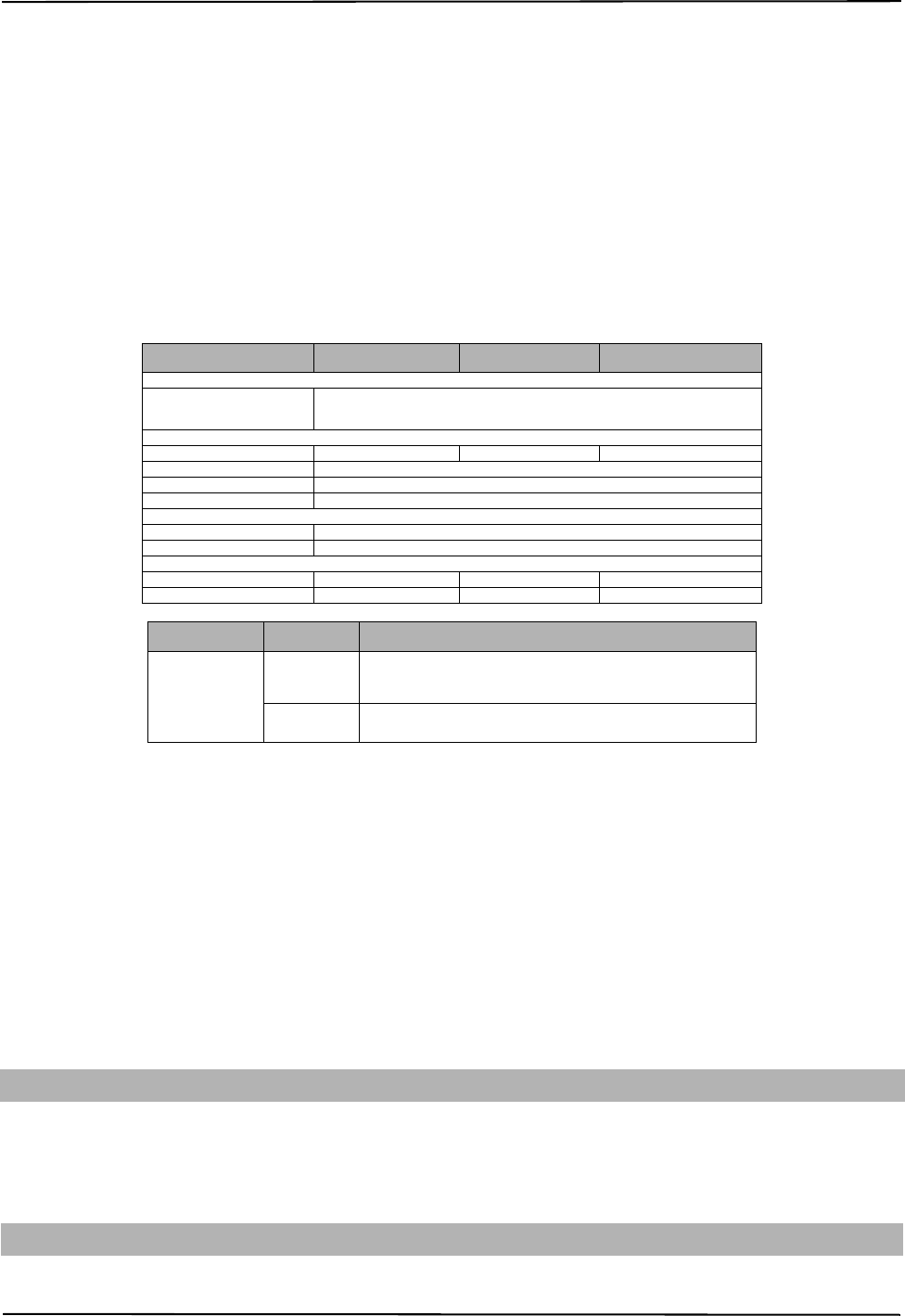
Table 1: Communicator Ratings
Model 3G2060R
3G/GPRS only TL260R
Ethernet only TL2603GR
Ethernet and 3G/GPRS
POWER SUPPLY RATINGS
• Input Voltage
Nominal 12 VDC:
The panel Bell output shall be derated:
700mA - (Communicator mA) = (derated Bell output).
CURRENT CONSUMPTION
• Standby Current
90mA @ 13.66V 100mA @ 13.65V 120mA @ 13.66V
• Alarm (Transmitting) Current
400mA @ 12V
• Operating Frequency
Quad band 850MHz, 900MHz, 1800MHz, 1900MHz
• Typical Antenna Gain
2dBi
ENVIRONMENTAL SPECIFICATIONS
• Operating Temperature
32°F - 120°F (0°C - 49°C)
• Humidity
5% ~ 93% relative humidity, non-condensing
MECHANICAL SPECIFICATIONS
• Board Dimensions (mm)
100 × 150 × 15 100 × 150 × 18 100 × 150 × 15
• Weight (grams) with bracket
310 290 320
Table 2: Compatible Receivers, and Panels
Communicator Receiver/
Panel Description
3G2060R
TL260R
TL2603GR
Receiver
• Sur-Gard System I Receiver, version 1.13+
• Sur-Gard System II Receiver, version 2.10+
• Sur-Gard SG-DRL3-IP, version 2.30+ (for Sur-Gard System III Receiver)
• Sur-Gard SG-DRL4-IP version 1.20+ (for Sur-Gard System IV Receiver)
Panel
• Power Series PC1616, version 4.5+
• Power Series PC1832, version 4.5+
• Power Series PC1864, version 4.5+
PRE INSTALLATION CONFIGURATION
COMMUNICATOR INSTALLATION CONFIGURATION

Installing the Ethernet Cable 3G Alarm Communicator Installlation Manual
6
person or other persons). The Communicator shall be installed and used within an environment that provides the pollution degree max 2, overvoltages category II, in
non-hazardous, indoor locations only. This manual shall be used with the Installation Manual of the panel which is connected to the 3G/GPRS/Ethernet Communica-
tor. All instructions specified within the panel manual must be observed.
All the local rules imposed by local electrical codes shall be observed and respected during installation.
Installing the Ethernet Cable
(TL260R/TL2603GR only)
A Category 5 (CAT 5) ethernet cable must be run from a source with Ethernet/Internet connectivity to the Communicator module, inside the Panel. The Com-
municator end of the cable must be terminated with an RJ45 plug, which will connect to the Communicator’s RJ45 jack after the Communicator is installed. All
requirements for installation of CAT5 ethernet cable must be observed for correct operation of the Communicator, including, but not limited to, the following:
• Do NOT strip off cable sheathing more than required for proper termination.
• Do NOT kink/knot cable.
• Do NOT crush cable with cable ties.
• Do NOT untwist CAT5 pairs more than ½ in. (1.2cm).
• Do NOT splice cable.
• Do NOT bend cable at right angles or make any other sharp bends.
NOTE: CAT5 specification requires that any cable bend must have a minimum 2 in. (5 cm) bend radius. Maximum length of CAT 5 cable is 328 ft.
(100 m).
Running the RS-422 Cable
An RS-422 cable must be connected to the C24-HUB and cable run to the Communicator module inside the panel.
NOTE: Maximum cable length for RS-422 cable is 1,000 ft. (305 m).
At the C24-HUB, make connections as follows:
1. Securely fasten the TX+ wire on the terminal block.
2. Securely fasten the TX- wire on the terminal block.
3. Install a 120
¼ W resistor between the RX + and RX- terminals at the C24-HUB.
4. Securely fasten the RX+ wire on the terminal block.
5. Securely fasten the RX- wire on the terminal block.
6. (Optional) Securely fasten the GND wire on the terminal block.
NOTE: The GND connection is optional. DSC recommends connecting the GND wire at both ends.
7. Run the RS-422 Cable from the
C24-HUB
to the inside of the Panel.
Inserting and Removing the SIM Card
1. Remove the front cover of the Panel to access SIM holder.
2. Remove power from the panel and disconnect the battery and telephone line.
3. On the SIM card holder push gently to slide the cover towards the Printed Circuit Board (PCB) antenna, as indicated by the arrow on SIM holder, to OPEN.
This will unlatch the SIM card holder on the side closest to edge of the Communicator PCB. (See Figure 3).
4. Lift up the SIM card holder from the side that is not hinged.
NOTE: The SIM can be damaged by bending, or scratching contacts. Use caution when handling SIM cards.
5. Insert or remove the SIM card, noting the orientation of the notches on the SIM card and the SIM card holder.
6. When inserting a SIM card, insert the card in the proper orientation and gently push the SIM card holder down and slide the holder as indicated by the arrow
on SIM holder, to LOCK.
7. Reconnect the backup battery and telephone line, apply AC power to panel, and replace the panel cover.
Hardware Reset
The Communicator can be hardware reset by installing a jumper between Pins 4 and 5 on the AUDIO/DEFAULT connector and restarting the Communicator.
Installing jumper during normal operation has no effect.
Installing Communicator with PC1616/1832/1864 Panel
NOTE: Before installing Communicator or inserting/removing SIM, ensure that system power is OFF and telephone line is disconnected.
1. To assemble supplied mounting bracket, perform the following: (See Figure 1).
a. Remove the 4 white plastic standoffs from the bag provided with the Communi-
cator kit.
b. Insert the 4 standoffs through the back of the mounting bracket, into the holes at
each corner. (The antenna mounting tab should be facing away from you).
c. Place the bracket on a flat, solid surface. Hold the Communicator component
side up and orient the 4 holes on the Communicator with the 4 standoffs pro-
truding from the bracket. Push the Communicator firmly and evenly onto the
standoffs until it is securely attached to the mounting bracket.
d. Remove the panel front cover.
e.
TL260R/TL2603GR only
: Remove and discard the circular knockout located in
the top-right section of the panel. (This hole will be used for connection of the sup-
plied radio antenna).
f. TL260R/TL2603GR only: Connect the supplied 5” (12.7 cm) antenna cable to
the radio, by passing the connector through the hole on back of the mounting
bracket to the Communicator board. Push the antenna connector firmly into
the socket on the 3G/GPRS radio. (See Figure 3).
2. Install the Communicator into the panel:
a. Attach one end of the PC-LINK cable to the panel PC-LINK header on the
panel (red wire goes on Pin 1 of the panel PC-LINK header).
b. Insert the assembled Communicator into the panel.
NOTE: Ensure that the threaded antenna connection point is visible through
the knockout hole at the top right of the panel.
c. TL260R/TL2603GR only: Place the nylon washer with bushing (thick flat washer) onto the threaded section of the antenna cable. Insert the threaded
section through the antenna mounting knockout hole at top right of panel.
d. Place the second nylon washer (flat), followed by the brass washer and the brass nut, onto the threaded section of the cable, outside the panel. Tighten
the assembly by hand only. (Finger tight only- Do not overtighten the antenna assembly).
INSTALLING THE 3G/GSM/ETHERNET COMMUNICATOR IN PANEL
DG0009744
Brass Washer
Nylon washer (flat)
Nylon Washer
with bushing
(thicker flat washer)
Brass nut
Antenna
Mounting Tab
Mounting
Holes
Mounting Holes
Antenna
Cable
Mounting Plate
for UA601
External Antenna
Screw Thread
Communicator
Board
Mounting
Plate
Stand Off
Figure 1 Communicator
Mounting Bracket
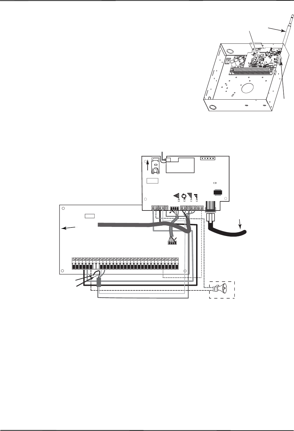
3G Alarm Communicator Installlation Manual Installing Communicator with PC1616/1832/1864 Panel
7
e. Locate the screw hole on the right side wall of the panel. See Figure 2 (screw). Line up the assembled
Communicator with the right side wall of the panel and, using the screw provided, secure the mounting
bracket to the panel.
f. Attach the other end of the PC-LINK cable to the Communicator (black wire goes on Pin 1 of the Com-
municator).
g. TL260R/TL2603GR only: Using light pressure (finger tight only), attach the supplied white quad band
whip antenna to the threaded antenna connection point at top of the panel.
WARNING!
3G2060R/TL260R/TL2603GR MODULES ARE POWER LIMITED. DO NOT ROUTE ANY WIRING
OVER THE CIRCUIT BOARD. MAINTAIN AT LEAST 1IN. (25.4MM) SEPARATION BETWEEN CIRCUIT
BOARD AND WIRING. A MINIMUM OF ¼ IN. (7MM) SEPARATION MUST BE MAINTAINED AT ALL
POINTS BETWEEN NON-POWER LIMITED WIRING AND POWER LIMITED WIRING.
3.To electrically connect the Communicator to the panel, perform the following steps (See Figure 3).
a. Disconnect both AC power and battery connections from the panel, and disconnect telephone line.
Module Power Connection
b. Attach a wire from the Communicator’s left PWR terminal to the panel’s BELL+ terminal.
NOTE: For ULC Commercial Fire Monitoring applications, do NOT connect any devices on the Bell + terminal
other than the Communicator.
c. Attach a wire from the Communicator’s GND terminal (beside PWR) to the panel’s AUX - terminal.
d. Attach a wire from the Communicator’s SHLD terminal to the panel’s EGND terminal.
(Protective earth ground).
(Optional) External Bell/Siren Connection
e. Attach a wire from the Communicator’s right PWR terminal to the positive (+) terminal on the Bell/
Siren.
f. Attach the panel’s BELL
-
terminal to the negative (
-
) terminal on the Bell/Siren.
NOTE: If an external Bell/Siren is not used, install the 1K
½W 5% resistor (Brown, Black, Red, Gold) (supplied with the panel) between the panel’s Bell + and
Bell
-
terminals, then only wire the BELL + to the PWR terminal on the Communicator.
g. Confirm that the SIM card is inserted in the holder and locked.
Keybus Connection for C24 Interactive
4. Install the Keybus cable between Communicator and Panel as follows:
WARNING: DO NOT CONNECT KEYBUS RED OR BLK WIRES TO THE PANEL OR
THE COMMUNICATOR TERMINAL BLOCKS.
a. Attach a wire from the Communicator YEL terminal to the panel YEL terminal.
b. Attach a wire from the Communicator GRN terminal to the panel GRN terminal.
RS-422 Connection for C24 Interactive
At the Communicator inside the Panel, connect the previously run RS-422 cable as follows:
1. Securely fasten the TX+ wire to RX+ on the terminal block.
2. Securely fasten the TX- wire to RX- on the terminal block.
3. Securely fasten the RX+ wire to TX+ on the terminal block.
4. Securely fasten the RX- wire to TX- on the terminal block.
5. (Optional) Securely fasten the GND wire on the terminal block.
NOTE: The GND connection is optional. DSC recommends connecting GND wire at both ends.
Install Network Cable (TL260R/TL2603GR only)
6. Route the CAT 5 Ethernet cable through back of the panel and plug it into the Communicator’s RJ45 jack.
Before leaving the premises the Ethernet communication lines must first be connected to an approved (acceptable to local authorities) type NID, (UL
installations, UL 60950 listed NID, for ULC installations CAN/CSA C22.2. No. 60950-1 Certified NID). All wiring shall be performed according to the local
electrical codes.
7. Perform the following steps for initial power on of the panel with Communicator installed:
a. Reconnect the AC power, telephone line, and battery + connector to the panel.
(The Communicator and Panel will power up together).
DG009545
PC-Link
Cable Connector
(screw)
Quad band
Whip Antenna
PC1616/1832/1864
GSM Radio
RJ-45
UA585
Use light pressure
to attach antenna
Finger Tight only.
Figure 2 PC1616/1832/1864 Control Panel
Figure 3 Communicator Wiring Diagram
AUDIO/DEFAULT
DSC
UA601
PC-LINK
PC-LINK
COM
TL260(R)
TL2603G(R)
3G2060(R)
AC
AC
Z1 COM Z2 Z3 COM Z4 Z5 COM Z6 Z7 COM Z8
AUX+
BELL +
PGM1 PGM3
RING
T-1
PC1616/1832/1864
3G Radio
+
-
UA503
1
To external antenna
Input Ratings from Bell +:
+11.1V ~ +12.6 VDC
100mA standby; 400mA alarm
DSC Panel min. power requirements:
- 16 VAC 40 VA transformer;
- 12 VDC 7Ah battery
+
-
External Bell/Siren
Black
Black
Jumper pins 4 and 5
to reset.
L
o
c
k
1
GRN
RS-422
To C24-HUB
Maximum cable length 305 m (1,000 ft)
From NID
TL2603G(R) / TL260(R)
Use only CAT5
Supervised
RJ-45
YEL
COM
PWR
GRN
YEL
TIP
R-1
BLK
RED
AUX -
BELL -
EGND
Do NOT
connect
Red or Black
Keybus wires!
TX+
GND
TX-
RX+
RX-
SHLD
Green
Yellow
SIM
Network Link
YELLOW
XX
PGM2 PGM4
Maximum cable length
100 m (328 ft)
PWR
DG0009745

Keypad Data Display 3G Alarm Communicator Installlation Manual
8
b. Observe that the Communicator’s red and yellow LEDs are flashing together while it initializes. The red and yellow LEDs will continue to flash until the
Communicator has successfully communicated to all programmed receivers. If this is the first time the Communicator has been powered up in the panel,
the module will initiate communication to Connect24 to request remote programming.
NOTE: Initialization may take several minutes to complete. red and yellow LEDs will flash together during initialization. Do not continue to next step until the red
and yellow LEDs have stopped flashing. (If only the yellow LED is flashing, there is a Communicator trouble and the Green LEDs are not valid for Communicator
Placement Test). Correct trouble indicated by flashes on yellow LED before continuing. (See Table 5 for troubleshooting assistance).
8. 3G2060R/TL2603GR only: Perform the Communicator Placement Test below.
9. Mount the Panel in final location indicated by placement test.
Domain Name Service (DNS) programming is not permitted in UL/ULC listed systems.
Keypad Data Display
NOTE: Programming locations accessible via the keypad are for viewing only. All communicator programming is modified via Connect24.
•Section-Toggle Options: The number is displayed when Toggle is ON, the number is not displayed when Toggle is OFF. (e.g., Toggle Options displays: [
--
3
--
6
--
]. Options 3 and 6 are ON, all others are OFF). Pressing keys 1 through 8 will alternately turn the Toggle ON and OFF.
•HEX/Decimal Data: Values that are provided with two defaults, separated by a “/” character, use the format: hexadecimal followed by decimal equivalent
(e.g., Default [0BF5/3061]). Hexadecimal numbers are shown, with all leading zeroes, to the full field length defined for the number.
Entering HEX values at keypad
To enter HEX values at the keypad, you must press the
*
key before entering the HEX value. (e.g., to enter “
C
” at the keypad, press
[*][3]
.
Entering ASCII Characters at keypad
1. Press [*] and use scroll buttons [<] [>] to display “ASCII Entry” on the LCD screen.
2. Press [*] to select ASCII entry mode.
3. Use the [<] [>] scroll keys to display the character you want and press [*] to save and exit ASCII.
4. Repeat the steps above to enter another ASCII character.
PC1616/1832/1864 Initial Programming
Perform the following steps to ensure that the Communicator and the Panel work together as intended.
These Sections must be programmed at the panel keypad. Enter
[*][8][Installer Code][Section Number]
. Record any values that are modified from their default,
in the appropriate Worksheets for the Panel or Communicator.
1. In Panel Section [167] program 060 (seconds).
2. In Panel Section [382] set Option [5] ON
NOTE: I
f this option is OFF, the yellow status LED on the Communicator will indicate ‘Panel Supervision Trouble’ (2 flashes) and the unit can not be programmed via the
PC-LINK cable.
3. In Panel Section [383] set Option [7] ON.
4. In Panel Section [383] set Option [8] ON for CID, or OFF for SIA.
5. A valid Account Number must be entered in Communicator Section [851][021]. See Programming Section.
NOTE: DSC recommends using the same Account Number for Panel and Communicator.
6. In Panel Sections [301], [302], and [303], program the central station telephone number that will be used for the 3G/GPRS/Ethernet Communicator. Valid
entries are:
a. A valid telephone number; signals will be routed to the central station using the PSTN.
b. DCAA (Receiver 0); signals will be routed to 3G/GPRS/Ethernet Receivers 1 - 4 depending on programming Toggle Options in Communicator Section
[851][006].
c. Panel Section [301] sets the Primary communication path, and may be configured as either PSTN or Communicator routing. Panel Section [302] is
redundant, and Panel Section [303] is the backup telephone number for Panel Section [301]. Refer to the Panel manual for additional information.
NOTE: The leading digit ‘D’ (dial tone detection) in the telephone number is pre-programmed.
7. In Panel Section [350], program the communication format as: CID (03) or SIA FSK (04).
NOTE: If any of the Panel telephone numbers have been set to DCAA, section [350] must be set to (04).
8. In Panel Sections [351] - [376], program the Communicator call direction options. Refer to the Panel Installation Manual for details on setting these options.
9. In Panel Section [401] set Toggle Option [2] ‘User Enable DLS’ to ON in order to perform panel DLS session through 3G/GPRS or Ethernet.
NOTE: Before leaving the premises, the installer should verify all programmed communications paths. See Programming Options Section
[851][901] to send immediate test transmissions.
Communicator Troubles displayed on a PC1616/1832/1864
The General System trouble is the only trouble that will appear on the keypad Liquid Crystal Display (LCD) when encountered by a Communicator installed in
a PC1616/1832/1864. For more information about the trouble on the Communicator module refer to the panel event buffer. Log entry will show Fault or
Restore for each of the following events:
•T-LINK Network Fault/Restore: This log will occur for the following trouble conditions: SIM Lock Trouble, 3G/GSM Trouble, Ethernet Trouble, or
Connect24 Configuration Trouble.
•T-LINK Receiver Trouble/Restore: This log will occur for the following trouble conditions: Receiver Not Available Trouble, Receiver Supervision Trouble,
or Failure to Communicate (FTC) Trouble.
•T-LINK Comm. Fault/Restore: This log will occur when the panel loses communications with the Communicator and will clear when communications is
restored.
(3G2060R and TL2603GR only).
To confirm that the 3G/GPRS antenna location is suitable for radio operation, perform the placement test as follows:
NOTE: You may need to relocate the Panel or install an optional extension antenna during this procedure, if radio signal strength is too low.
1. Confirm that the yellow LED on the Communicator is not flashing. A flashing yellow LED indicates trouble on the Communicator. See Table 5 to trouble-
shoot and correct the cause of this trouble before continuing to the next step.
2. Observe the strength of the radio signal on the yellow LED and the 2 green LEDs on the Communicator meet or exceed the minimum signal level requirement.
Minimum Signal Level: The yellow LED is OFF and the Green LED 1 (furthest from the yellow LED) is ON. (i.e., not flashing) for the panel location to be accept-
able. See table for “Radio Signal Strength” on page 9 for interpretation of receiver signal strength on LEDs.
NOTE: If the required signal strength is too low with the panel in its current location, the panel must be relocated or an external antenna is
required.
a. If required, the following 3G/GSM extension antenna kits are available to the installer:
•GS15-ANTQ - 4.57m (15’)Internal Antenna Extension Kit (Suitable for interior mounting only).
•GS25-ANTQ - 7.62m (25’)External Antenna Extension Kit (Suitable for exterior mounting only).
•GS50-ANTQ - 15.24m (50’)External Antenna Extension Kit (Suitable for exterior mounting only).
Specific instructions for the installation of the extension antenna are included with the kit. Observe all the electrical safety instructions regarding the installation
of the antenna. All the wiring of the equipment shall be fully compliant with the local rules and regulations.
3. If required, install the antenna extension and perform the following steps to determine the best location for placement of the antenna :
a. Disconnect the white whip antenna from the panel.
b. Attach one end of the antenna extension cable to the threaded antenna connector on the panel and the other end to the external antenna.
4. Move the extension antenna to various locations while observing the two Green LEDs on the panel.
a. Continue to reposition the extension antenna until you receive an acceptable (minimum one green LED ON solid) signal strength.
NOTE: Minimum strength is: green LED 1 flashing and yellow LED OFF. If green LED 1 is flashing, relocation should be considered.
b. Mount the supplied antenna extension bracket at the location that provides the best signal strength.
INITIAL PANEL PROGRAMMING
COMMUNICATOR PLACEMENT TEST
3G Alarm Communicator Installlation Manual Yellow Trouble LED
9
5. Alternately, you can reposition the Panel to improve signal strength. Dismount the panel and move it to another location to achieve the required signal
strength. If the Panel is relocated to improve signal strength, mount it in the new location.
6. When final Panel/antenna location is determined, continue at the Initial Panel Programmingsection.
The Communicator has 4 onboard LED indicators. These include 1 yellow trouble LED, 1 red Network Connection Status LED, and 2 green Signal Strength
LEDs. The LED meaning is described in this Section.
Yellow Trouble LED
This yellow LED will flash to indicate a trouble on the unit. The number of flashes indicates the type of trouble. See the table below for the coded flashes and
the conditions which will activate the Trouble Status LED.
NOTE: Only the highest priority trouble (2 Flashes is the highest priority trouble) is indicated. When this trouble is restored, the next highest trouble will indi-
cate, if present. This will continue until all troubles have been cleared. (yellow LED is not flashing).
The following paragraphs describe the conditions associated with the trouble indicated:
Panel Supervision Trouble (2 Flashes)
This trouble will be indicated when communication between the Communicator module and the Panel fails. If the module can not communicate with the Panel
(e.g., loss of power to the panel) the Communicator will send the ‘Panel Absent Trouble Event’ message to the central station receiver. When communication
returns, a ‘Panel Absent Restore Event’ is sent by the Communicator to the central station receiver. The reporting codes are ET0001 for Trouble and ER0001
for Restore. The panel absent event always uses the primary receiver account code when communicating to the central station.
NOTE: The Panel Supervision Trouble/Restore are internally generated events by the Communicator. They are the only internal events; all other events are gen-
erated by the panel. Trouble is generated if the Communicator misses 6 Polls. Trouble is restored on receipt of first Poll from the Panel.
SIM Lock Trouble (4 Flashes)
This trouble will signify that the SIM lock feature has been enabled and the unit has not been programmed with the correct PIN for the SIM card.
3G/GSM Trouble (5 Flashes)
This trouble is indicated for any of the following 4 conditions:
1. Radio Failure: Trouble is indicated after 8 failed attempts to communicate with the 3G/GPRS radio.
2. SIM Failure: Trouble is indicated after 10 failed attempts to communicate with the SIM.
3. 3G/GPRS Network Trouble: Trouble is indicated for loss of the registration to the network provider.
4.
Insufficient Signal Strength
: Trouble is indicated if
calculated
average
signal strength is too low. (Both green LEDs are OFF). Trouble will clear when the calcu-
lated average signal strength is above minimum (i.e., > CSQ 5).
Ethernet Trouble (6 Flashes)
This trouble is indicated when Ethernet link between the transmitter and the local switch or router is absent. This trouble will also be indicated if the unit fails to
get Dynamic Host Control Protocol (DHCP) settings from the DHCP server. (Not active if Ethernet Receivers are not programmed).
Receiver Not Available (7 Flashes)
This trouble is indicated if the unit is not able to successfully initialize with any of the programmed receivers. Unprogrammed receivers are excluded. This trou-
ble is also indicated if the 3G/GPRS receiver APNs have not been programmed in Sections [205] and [215].
Receiver Supervision Trouble (8 Flashes)
This trouble is indicated when receiver supervision is enabled and communication between the Communicator module and the receiver fails. Trouble is indi-
cated if Ethernet 1 is supervised and does not receive a heartbeat from the receiver or if 3G/GPRS is supervised and the unit does not receive an acknowledg-
ment to 4 heartbeats sent to the receiver.
FTC Trouble (9 Flashes)
This trouble is indicated when the unit fails to communicate module events to the central station. Trouble is displayed after the unit has exhausted all commu-
nications attempts to all programmed receivers for events generated by the Communicator.
Configuration Failure (10 Flashes)
This trouble is indicated when the unit fails to receive remote programming.
Remote Programming (11 Flashes)
This trouble is indicated during a remote firmware upgrade. Indicates that a remote firmware update is in progress over 3G/GPRS/Ethernet. Trouble will clear
automatically when update completes successfully.
Module Configuration Trouble (12 Flashes)
This trouble is indicated when the System Account Code or the Receiver Account have not been programmed. Disabled receivers are excluded.
Red Network Connection Status LED
(
TL260R/TL2603GR
)
BLINKING: Indicates communications in progress.
• Once quickly for outgoing Ethernet transmission.
• Twice quickly to indicate incoming Ethernet ACK/NACK.
OFF: This is the normal state of the Red Network Connection Status LED. There are no network connection issues present.
ON
: There is a problem with the Ethernet or the 3G/GPRS network connection. LED will be ON if any of the following occur:
• Ethernet cable is not connected,
• DHCP configuration times out,
• Unit fails to get an IP address from the 3G/GPRS network, or
• 3G/GPRS connection has been reset.
(Green LED 1) (Green LED 2) and (Yellow LED) Signal Strength
NOTE: If the yellow LED is flashing, Signal Strength in table below is not valid.
See
Table 5
for troubleshooting flashing yellow LED.
COMMUNICATOR STATUS LEDS
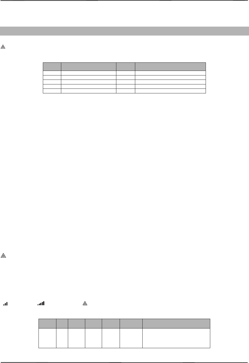
Table 3: Yellow Trouble Status LED
# of
Flashes Trouble # of
Flashes Trouble
2 Panel Supervision Trouble 8 Receiver Supervision Trouble
4 SIM Lock Trouble 9 FTC Trouble
5 3G/GSM Trouble 10 Configuration Failure
6 Ethernet Trouble 11 Remote Programming
7 Receiver Not Available Trouble 12 Module Configuration Trouble
Table 4: Radio Signal Strength
Signal
Strength CSQ
Level Yellow
LED Green
Led 2 Green
LED 1 Signal Level
dBm Action Required
No Signal 0 ON OFF OFF -108.8
• Check all antenna connections.
• Confirm 3G/GPRS service is active in
area.
• Relocate Panel or install external
antenna.

Network Activity LEDs (Red and Green) 3G Alarm Communicator Installlation Manual
10
NOTE: The Communicator will indicate 3G/GSM Trouble (yellow LED = 5 flashes) if the calculated average CSQ Level is 5 or less. The Communicator Signal
Strength can be viewed remotely with Connect24.
Network Activity LEDs (Red and Green)
(TL2603GR only)
•Ethernet Activity: Red LED will blink quickly once for Ethernet Transmit, or twice for Ethernet Receive.
•3G/GPRS Activity: Green LED 2 will blink quickly once for 3G/GPRS Transmit, or twice for 3G/GPRS Receive.
Network Link LED (Yellow)
(TL260R only) See Figure 3 for location of LED.
The TL260R uses an additional Link LED on the board. LED is lit to indicate an active Ethernet connection.
.
Factory Defaults Reset
You can reset the programming options for the Communicator to the factory settings by installing the hardware jumper. Perform the following steps to reset the
Communicator:
NOTE: A jumper is required on AUDIO/DEFAULT pins 4 and 5 to reset the hardware values.
1. Remove Panel front cover.
2. Locate the AUDIO/DEFAULT 5 pin connector on the Communicator board. (See Figure 3).
3. Apply a jumper to short the hardware default pins 4 and 5.
4. Remove AC and DC power from the panel and then reapply power to the Panel. Wait until the two green LEDs on the Communicator begin flashing rapidly.
5. Remove the jumper from the hardware default pins 4 and 5. (Green LEDs will stop flashing).
6. Replace the Panel cover.
NOTE: Your Communicator has now been reset to the factory default values.
Firmware Update
The firmware of the device can be updated over 3G/GPRS or Ethernet (Remote or Local updating):
• When the firmware update begins, all 4 LEDs are ON.
• During the firmware update process, the LEDs will be cycled individually in a chaser pattern.
• After a successful update, the unit will automatically restart.
• Should the update fail, all 4 LEDs will flash ON, then OFF together at 1 second intervals.
NOTE: If the firmware update fails, restart the Communicator by cycling Power. For persistent update failures, contact your dealer. For UL/ULC listed installa-
tions, only local firmware updates are allowed.
1 Bar 1 - 4 ON OFF Flashing -108 ~ -103 Relocate Panel or install external antenna
if Yellow Trouble LED has:
5 flashes.
2 Bars 5 - 6 OFF
See Note OFF Flashing -102 ~ -99
3 Bars 7 - 10 OFF OFF ON -98 ~ -91
Location is OK
. 3G/GPRS Signal Strength
is greater than CSQ 5.
4 Bars 11-13 OFF Flashing ON -90 ~ -85
5 Bars 14 + OFF ON ON -84 and
higher
COMMUNICATOR RESET / UPDATE
Table 4: Radio Signal Strength (Continued)
Signal
Strength CSQ
Level Yellow
LED Green
Led 2 Green
LED 1 Signal Level
dBm Action Required

3G Alarm Communicator Installlation Manual Firmware Update
11
_____________________________________________________________________________________________________________________________________________________________________________________________________________________________________________________________
APPENDIX A: COMMUNICATOR TROUBLESHOOTING
Table 5: Trouble LED indications
Trouble
indication Possible
Causes Trouble Possible Solution
No Indication No Power
• Check the power connections between the Panel and the Communicator.
• Confirm PC-LINK cable is properly installed between communicator and panel.
Yellow LED –
ON Solid Insufficient
Signal Strength
• Confirm that 3G/GPRS network service is active in your area.
• Ensure the antenna is securely connected to the radio. Check antenna stub cable is
securely connected to the radio.
• If an external antenna is used ensure the antenna is securely screwed on to the antenna
cable connector. Check external antenna for damage or open/short.
Trouble LED –
2 Flashes
Panel
Supervision
Trouble
• Check Section [382]Toggle Option[5] is ON.(3G/GPRS/Ethernet Module Enabled)
• Ensure the PC-LINK cable between the Panel and Communicator is connected properly
(not reversed) and is securely in place.
Yellow LED -
4 Flashes Lockout
Trouble
• The SIM card has incorrect PIN programmed or has a PIN that the module does not rec-
ognize. Replace the SIM card.
Yellow LED –
5 Flashes 3G/GSM Trou-
ble
• Confirm that 3G/GPRS service is available and active in your area.
• Check all antenna connections.
• Ensure
average
radio signal strength is CSQ
6
or higher. (See Table 4 ).
• Ensure the SIM card is properly inserted into the SIM card holder.
• Ensure the SIM card has been activated. (Could take up to 24 hrs after install).
• If this trouble persists, you must relocate the Panel (and Communicator) or install an
external antenna extension kit.
Yellow LED –
6 Flashes Ethernet
Trouble
• Check with your ISP to confirm Internet service is active in your area.
• Ensure your Ethernet cable is securely inserted into the RJ45 jack of the Communicator
and the Hub/Router/ Switch.
• Check the link light on the Hub/Router/ Switch is ON . If link light is OFF, try restarting the
Hub/Router/ Switch.
• If DHCP is used, ensure that the unit has an assigned IP address from the server. In
Section [851] [992] verify a valid IP address is programmed. If not, contact the Network
administrator.
• If problem persists, replace the Ethernet cable and RJ45 connector.
Yellow LED –
7 Flashes Receiver Not
Available
• Ensure that the Ethernet path has internet connectivity.
• If you are using a static IP address make sure the gateway and subnet mask are entered
correctly.
• If the network has a firewall, ensure the network has the programmed
outgoing ports open (Default UDP Port 3060 and Port 3065).
• Ensure that all the receivers are programmed for DHCP or have the proper IP address
and port number.
• Ensure the 3G/GPRS Receiver APNs have been programmed with the Access Point
Name provided by your 3G/GPRS provider.
Yellow LED –
8 Flashes
Receiver
Supervision
Trouble
• This trouble is indicated when supervision is enabled and the unit is not able to success-
fully communicate with the receiver.
• If this trouble persists, contact your central station.
Yellow LED -
9 Flashes FTC Trouble
• The unit has exhausted all communications attempts to all programmed receiver for
events generated by the Communicator.
• Restart the system, if trouble persists, contact your dealer.
Yellow LED –
10 Flashes
Connect24
Configuration
Failure
• The SIM is active but there is no programming for the Communicator.
• Ensure a profile has been programmed in Connect 24 for the SIM.
• You can confirm your programming by calling the Connect 24 VRU, or by logging into
the Connect24 VRU web site.
Yellow LED –
11 Flashes Remote
Programming
• The LEDs will flash when a remote firmware upgrade is in progress over Ethernet or 3G/
GPRS. The LEDs will extinguish when update is complete.
• The LEDs will flash to indicate a remote programming session is active over Ethernet or
3G/GPRS. The LEDs will extinguish when the session terminates.
Yellow LED –
12 Flashes
Module
Configuration
Trouble
• This indication appears when Section [021] System Account Code or
Section [101]; [111]; [201]; and [211] Receiver Account Code have not been pro-
grammed. Ensure that a valid account code has been entered in these Sections.
All LEDs flash-
ing together Boot Loader
Failed
• Disconnect power, then reconnect power to the Communicator module.
Red and Yellow
LEDs flashing
together
Initialization
Sequence
• The unit is still initializing please wait while the unit gets its programming and establishes
a connection to all programmed receivers.
Note: This process may take several minutes to complete.
Only Green
LEDs flashing Hardware
Default Jumper
• The hardware default jumper is installed and must be removed. See Figure 3.

System Options 3G Alarm Communicator Installlation Manual
12
The Programming Sections described in this document can be viewed at the SCW LCD. To start programming enter: [*][8][installer
code] [851][# # # ], Where ### is the 3 digit Section number referenced in this section. The Programming Worksheets at the end of
this document can be used to record the new values when programming changes have been made from the default values.
Programming Sections are accessed through Connect24. Installers may review/record programming Options at the panel.
NOTE: Ethernet/Cellular Programming Sections accessed through the panel are for display purposes only. Configuration changes
must be done using Connect24.
SYSTEM OPTIONS
[001] Ethernet IP Address
Default (000.000.000.000)
Enter the IP address of the Communicator. Ensure that the IP address is unique to your Communicator on the local network. Format is 4
fields, each field is a 3 digit decimal number. Valid range: 000-255. If an IP address is programmed in this Section, the unit will operate
with Static IP (DHCP disabled). Sections [002] and [003] must also be programmed when using Static IP addresses.
NOTE: Default for this Section is Dynamic Host Configuration Protocol (DHCP) enabled. When enabled, the DHCP Server will set
values for: IP Address [001], Subnet Mask [002], and Gateway [003]. Programming an IP address in this Section will disable
DHCP (Static IP).
[002] Ethernet IP Subnet Mask
Default (255.255.255.000)
Enter the Ethernet IP Subnet Mask of the Communicator. Format is 4 fields, each field is 3 digits. Valid range: 000-255.
NOTE: If DHCP is enabled, the DHCP Server will assign the subnet mask for this Section and the
programmed value will be ignored.
[003] Ethernet Gateway IP Address
Default (000.000.000.000)
Enter the Ethernet Gateway IP address of the Communicator. The gateway IP address is required when a router is used on the local net-
work to reach the destination IP address specified in Section [001]. Format is 4 fields, each field is a 3 digit decimal number. Valid
range: 000-255.
NOTE: If DHCP is enabled, the DHCP Server will assign the Gateway IP address for this Section and the programmed value will be
ignored.
[004] Receiver Supervision Interval
Default (0087/135)
When receiver supervision is enabled (ON) in Section [005] Toggle Option [3], the unit sends heartbeats to Ethernet Receiver 1 or Cel-
lular Receiver 1 to test the communications path. Use this Section to set the interval time (in seconds) when heartbeats will be sent to
the receivers. Valid range 000A-FFFF seconds. If the programmed value is less than (000A/10) seconds, supervision is disabled.
•Receiver Window: This is the supervision timeout that must be configured at the central station receiver.
•Recommended Values: This is the recommended heartbeat interval that should be programmed into the Communicator.
• For ULC installations, the Daily test transmission must be enabled over each available communication channel Sections [125] and
[225]. When programming with Connect24, the recommended intervals will be programmed automatically when the required win-
dow is selected.
[005] System Toggle Options
[1] Ethernet Receiver 1 Supervised
Default (OFF)
(TL2603GR/TL260R only).
ON: Ethernet Receiver 1 will be supervised and heartbeats will be sent to Ethernet Receiver 1 based on the supervision interval pro-
grammed in Section [004].
OFF: Ethernet Receiver 1 will not be supervised. When disabled, heartbeat 1 is sent to the Ethernet receiver once every hour, regardless
of supervision type (heartbeat 1 or 2). The heartbeat is resent every 5 seconds until ACK. If no event or heartbeat ACK is received after
(Receiver Supervision Interval + 75 seconds), Supervisory trouble is indicated.
NOTE: Ethernet Receiver 2 can not be supervised.
[2] Cellular Receiver 1 Supervised
Default (OFF)
ON: Cellular Receiver 1 will be supervised and heartbeats will be sent to Cellular Receiver 1 based on the supervision interval pro-
grammed in Section [004]. If ACK to heartbeat is not received, it is retransmitted every 5 seconds. Failure to ACK 2 consecutive heart-
beats will reset the radio.
OFF: Cellular Receiver 1 will not be supervised. When disabled, heartbeat is not sent to the receiver. Supervisory trouble is indicated.
NOTE: Cellular Receiver 2 can not be supervised.
[3] Supervision Type
Default (OFF)
ON: Heartbeat 1 (Commercial Supervision). This supervision type is suitable for applications where swap detection is required on the
supervisory packet.
OFF: Heartbeat 2 (Residential Supervision). This supervision type is suitable for applications where supervision of the communication
path to the receiver is required. (no swap detection).
ETHERNET/CELLULAR PROGRAMMING OPTIONS

3G Alarm Communicator Installlation Manual System Options
13
NOTE: Commercial supervision is more data intensive than residential supervision and should only be used when required to meet the
approval for the installation.
[4] Primary Path
Default (OFF - TL2603GR/TL260R) (ON - 3G2060R)
ON: Cellular channel is the primary path. Ethernet channel is the secondary path, if it exists.
OFF: Ethernet channel is the primary path in a dual Communicator. Cellular channel is the secondary path.
[5] Redundant Communications
Default (OFF) (TL260R only)
ON: Events will be communicated to Ethernet Receiver 1 and Cellular Receiver 1 at the same time. Events will be communicated to
Ethernet Receiver 2 and Cellular Receiver 2 at the same time. As long as the event is successfully communicated to 1 of the 2 paths
(Ethernet or Cellular) the Communicator will move on to the next event.
NOTE: Do not configure Ethernet Receiver 1 and Cellular Receiver 1 to communicate using a common receiver configuration (i.e.,
identical Receiver IP address and Receiver Remote Port). OFF: Events will be communicated to the receivers individually.
Toggle should be OFF when guaranteed message delivery to both receivers is required.
[6] Remote Firmware Upgrade
Default (ON)
ON: The Communicator module firmware can be remotely upgraded using the Ethernet/Cellular paths.
OFF: The Communicator module firmware can not be remotely upgraded. Local firmware upgrade is still possible.
[7] Alternate Test Transmissions
Default (OFF).
ON: When the periodic test transmission interval occurs, the test transmission will alternate between being sent to the primary and sec-
ondary receivers with each test transmission interval.
OFF: When the periodic test transmission interval occurs, the test transmission will be sent to the programmed receivers, based on the
settings of the periodic test transmission reporting codes.
[8] Cellular Low Signal Trouble.
Default (OFF)
This option masks the Low Signal trouble from the Cellular trouble event.
ON: A Cellular Trouble event is transmitted to receiver when the radio signal level falls below threshold level (average CSQ level is 4
or less).
OFF: A Cellular Trouble event is not transmitted to receiver when the radio signal level falls below threshold level (average CSQ level
is 4 or less).
[006] System Toggle Options 2
[1] Ethernet 1 Receiver Enabled.
Default (ON) (OFF for 3G2060R).
ON: Ethernet Receiver 1 is enabled.
OFF: Ethernet Receiver 1 is disabled.
[2] Ethernet 2 Receiver Enabled.
Default (ON) (OFF for 3G2060R).
ON: Ethernet Receiver 2 is enabled.
OFF: Ethernet Receiver 2 is disabled.
[3] Reserved. ( ).
[4] Cellular 1 Receiver Enabled.
Default (ON).(OFF for TL2603GR)
ON: Cellular Receiver 1 is enabled.
OFF: Cellular Receiver 1 is disabled.
[5] Cellular 2 Receiver Enabled.
Default (ON).(OFF for TL2603GR)
ON: Cellular Receiver 2 is enabled.
OFF: Cellular Receiver 2 is disabled.
[6] Reserved ( ).
[7] DLS Over Cellular.
Default (ON).
NOTE: Program this toggle as OFF if you want to completely disable DLS from using the Cellular path.
ON: DLS is enabled on the Cellular path.
OFF: DLS is disabled on the Cellular path.
NOTE: If this Toggle is OFF, DLS sessions will occur on the Ethernet path only, regardless of Primary Path set in Section [005] Toggle
Option [4]. If it is ON then the Communicator will connect to the Primary path first for DLS and if the session fails, the Sec-
ondary path will be used.
[8] Reserved ( ).
[007] DNS Server IP 1
Default (000.000.000.000)
Programming this Section is not permitted on a UL/ULC listed system.

Programming Options 3G Alarm Communicator Installlation Manual
14
Enter the IP address for DNS Server 1. Format is 4 fields, each field is a 3 digit decimal. Valid range: 000-255.
NOTE: If no value is programmed and DHCP is used, the DHCP Server will configure the address. If an address is programmed and
DHCP is used, the address that you program will be used instead of the DHCP address.
[008] DNS Server IP 2
Programming this Section is not permitted on a UL/ULC listed system.
Default (000.000.000.000)
Enter the IP address for DNS Server 2. Format is 4 fields, each field is a 3 digit decimal. Valid range: 000-255.
NOTE: If no value is programmed and DHCP is used, the DHCP Server will assign this value. If an address is programmed and DHCP
is used, the address that you program will be used instead of the DHCP address.
PROGRAMMING OPTIONS
[010] System Toggle Option
Default (Disable)
[1] This bit is used to enable/disable two way audio over 3G.
[011] Installer Code
Default (CAFE)
Program your installer code for this Communicator module. The installer code will be required when programming the Communicator
module. Valid range: 0000 - FFFF.
[012] DLS Incoming Port
Default (0BF6/3062)
The DLS Incoming Local Port (listening port) is the port DLS IV will use when connecting to the Communicator. If a router or gateway
is used, it must be programmed with a Transmission Control Protocol (TCP) port forward for this port to the Communicator module IP
address. Valid range: 0000 - FFFF.
[013] DLS Outgoing Port
Default (0BFA/3066)
The DLS Outgoing Port is used for outgoing session to DLS IV after an SMS request has been sent to the Communicator. Use this Sec-
tion to set the value of the local outgoing port. The value must be changed if the Communicator is located behind a firewall and must be
assigned a particular port number, as determined by your network administrator. In most cases, changing the default value or configur-
ing your firewall with this port is not required.
Valid range: 0000-FFFF.
NOTE: If Section [006] Toggle Option [7] is ON, DLS will use the Primary path for session. If Section [006] Toggle Option [7] is OFF
DLS will use the Ethernet path, if available.
[021] Account Code
Default (FFFFFF)
The account code is included when transmitting any events generated by the Communicator. (e.g., Panel Absent Trouble). It is recom-
mended that the account code be the same as the control panel account number. Valid range: 000001-FFFFFE. If 4 digit account codes
are needed the 2 lowest digits shall be programmed as FF.
(e.g., Account 1234 is programmed as:1234FF).
NOTE: Programming this Section with all 0 or F will cause a Module Configuration Trouble.
[022] Communications Format
Default (04)
Program 03 for Contact ID (CID). Program 04 for SIA. The module can be configured to send Events in SIA or CID format. The SIA
communication format follows the level 2 specifications of the SIA Digital Communication Standard - October 1997. This format will
send the account code along with its data transmission. The transmission will look similar to the following at the receiver. Example:
Nri0 ET001
Where: N = New Event; ri0 = Partition/Area identifier; ET = Panel Absent Trouble; 001 = Zone 001.
COMMUNICATIONS REPORTING CODES
[023] Panel Absent Trouble
Default (FF)
Program 00 to disable this event or FF to enable. This event will occur when communications with the panel have been lost for more
than 60 seconds.
Table 6: Communications Reporting Codes
Event SIA
Identifier
SIA
Reporting
Code
CID
Qualifier
CID
Event
Code
CID
Reporting
Code
CID
User/
Zone
[023] Panel Absent Trouble ET 001 1 3 55 001
[024] Panel Absent Trouble Restore ER 001 3 3 55 001
[025] Radio Activation Restore RS 001 3 5 52 001
[026] Ethernet 1 Test Transmission RP 001 1 6 A3 951
[027] Ethernet 2 Test Transmission RP 002 1 6 A3 952
[028] Cellular 1 Test Transmission RP 003 1 6 A3 955
[029] Cellular 2 Test Transmission RP 004 1 6 A3 956
[030] FTC Restore YK 001 3 3 54 001

3G Alarm Communicator Installlation Manual System Test Options [026 - 029]
15
[024] Panel Absent Trouble Restore
Default (FF)
Program 00 to disable this event or FF to enable. This event will occur when communications with the control panel have resumed.
[025] Radio Activation Restore
Default (FF)
Program 00 to disable this event or FF to enable. This event will occur after any successful Connect24 programming session.
SYSTEM TEST OPTIONS [026 - 029]
Test Transmissions to Primary Receiver, with Backup to Secondary Receiver:
Set Ethernet Section [026] to (FF); [027] to (00). Set Cellular Section [028] to (FF); [029] to (00).
• If the test transmission fails to the primary receiver it will backup to the secondary receiver.
• If the test transmission fails to the secondary receiver an FTC trouble will be generated.
Test Transmission Unique to Primary and Secondary Receivers:
Set Ethernet Section [026] to (FF); [027] to (FF). Set Cellular Section [028] to (FF); [029] to (FF).
• The module will send periodic test transmissions to each receiver independently, with no backups.
• If the test transmission fails to any of the programmed receivers, an FTC trouble will be generated.
Alternate Test Transmission:
Alternate Test Transmission can be enabled or disabled in Section [005] Toggle Option [7].
[026] Ethernet 1 Transmission
Default (FF)
Program 00 to disable this event transmission or FF to enable. See System Test Options (above) for details on settings.
[027] Ethernet 2 Transmission
Default (00)
Program 00 to disable this event transmission or FF to enable. See System Test Options (above) for details on settings.
[028] Cellular 1 Transmission
Default (FF)
Program 00 to disable this event transmission or FF to enable. See System Test Options (above) for details on settings.
[029] Cellular 2 Transmission
Default (00)
Program 00 to disable this event transmission or FF to enable. See System Test Options (above) for details on settings.
NOTE: The time interval (in minutes) between periodic tests is programmed in Section [125] (Ethernet) and Section [225] (Cellular).
[030] FTC Restore
Default (FF)
Program 00 to disable this event transmission or FF to enable. This event will occur when an FTC Trouble on the system restores.
[033] Communicator Firmware Update Begin
Default (FF);
Program 00 to disable this event transmission or FF to enable. This event will occur when the communicator firmware update begins.
[034] Communicator Firmware Update Successful
Default (FF);
Program 00 to disable this event transmission or FF to enable. This event will occur when the communicator firmware update success-
fully completed.
[035] Panel Firmware Update Begin
Default (FF);
Program 00 to disable this event transmission or FF to enable. This event will occur when the panel firmware update begins.
[036] Panel Firmware Update Successful
Default (FF);
Program 00 to disable this event transmission or FF to enable. This event will occur when the panel firmware is updated successfully.
[037] Panel Firmware Update Fail
Default (FF);
Program 00 to disable this event transmission or FF to enable. This event will occur when the panel firmware updated has failed.

Ethernet Receiver 1 Options 3G Alarm Communicator Installlation Manual
16
Table 7: Panel Tamper Alarm Restore
ETHERNET RECEIVER 1 OPTIONS
[101] Ethernet Receiver 1 Account Code
Default (0000000000)
The account code is used by the central station to distinguish between transmitters. This account code is used when transmitting heart-
beat signals to the central station receiver. Signals received from the Panel will use the control panel account number. Valid range:
0000000001-FFFFFFFFFE. Programming all 0 or all F will cause a Module Configuration Trouble.
NOTE: If Ethernet Receiver 1 and Cellular Receiver 1 are programmed as the same receiver (IP and port number are identical), Ether-
net Receiver 1 account code will be used.
[102] Ethernet Receiver 1 DNIS
Default (000000)
The Dialled Number Information Service (DNIS) is used in addition to the Account Code to identify the Communicator module at the
central station. Valid range: 000000 - 099999. Value is entered as a leading 0 followed by the 5 digit DNIS. Format is Binary Coded
Decimal (BCD).
NOTE: Each Ethernet/Cellular receiver must be programmed with a unique DNIS.
[103] Ethernet Receiver 1 Address
Default (127.000.000.001)
The default address enables the Communicator to operate in Unattended Mode.
Unattended Mode is used when a receiver is not available and the unit is required to perform DLS sessions. Typically used where the
customer programs the control panel daily due to access control and still wants to receive alarms without buying extra hardware
(receiver) or software.
NOTE: When a valid IP address has been programmed, Ethernet Receiver 1 is enabled and will communicate events over the Ethernet
channel.
Ethernet Receiver 1 and Cellular Receiver 1 may be configured to communicate to the same central station receiver. To configure the
device to operate using this Common Receiver Mode functionality, program Ethernet Receiver 1 and Cellular Receiver 1, IP address
and port number with identical values.
NOTE: When operating in Common Receiver Mode, Ethernet Receiver 1 account code will be used for Ethernet and Cellular.
[104] Ethernet Receiver 1 Remote Port
Default (0BF5/3061)
This Section determines the remote port of Ethernet receiver 1. Valid range: 0000 - FFFF.
[105] Ethernet Receiver 1 Local Port
Default (0BF4/3060)
Use this Section to set the value of the local outgoing port. Set the value of this port when your installation is located behind a firewall
and must be assigned a particular port number as determined by your central station
system administrator. Valid range: 0000 - FFFF.
[106] Ethernet Receiver 1 Domain Name
Default ( )
Enter the Domain Name as 32 ASCII characters.
Programming this Section is not permitted on a UL/ULC listed system.
ETHERNET RECEIVER 2 OPTIONS
[111] Ethernet Receiver 2 Account Code
Default (0000000000)
The account code is used by the central station to distinguish between transmitters. The account code is used when transmitting heart-
beat signals to the central station receiver. Signals received from the control panel will use the control panel account number. Valid
range: 0000000001- FFFFFFFFFE. Programming all 0 or all F will cause a Module Configuration Trouble (yellow LED=12 flashes).
NOTE: If both Ethernet Receiver 2 and Cellular Receiver 2 are the same receiver (IP and port number are identical), Ethernet Receiver
2 account will be used for Ethernet and Cellular.
Event SIA
Identifier
SIA
Reporting
Code
Contact ID
Qualifier Contact ID
Event Code
Contact ID
Reporting
Code
Contact ID
User/Zone
[033]Comm. FW Update
Begin LB 00 1 9 03 002
[034]Comm. FW Update Suc-
cessful LS 00 3 9 03 002
[035]Panel FW Update Begin LB 00 1 9 03 003
[036]Panel FW Update Suc-
cessful LS 00 3 9 03 003
[037]Panel FW Update Fail LU 00 1 9 04 003

3G Alarm Communicator Installlation Manual Ethernet Options
17
[112] Ethernet Receiver 2 DNIS
Default (000000)
The DNIS is used in addition to the account code to identify the Communicator module at the central station. Valid range: 000000 -
099999. Value is entered as leading 0 followed by the 5-digit DNIS. Format is BCD.
NOTE: Each Ethernet/Cellular receiver must be programmed with a unique DNIS.
[113] Ethernet Receiver 2 Address
Default (000.000.000.000)
Programming the Ethernet receiver 2 IP address with 000.000.000.000 will disable Ethernet.
Enter the Ethernet receiver 2 IP address. This address will be provided by your central station system administrator. Format is 4 fields,
each field is a 3-digit decimal. Valid range: 000-255.
NOTE: When a valid IP address has been programmed, Ethernet Receiver 2 is enabled and will communicate events over the Ethernet
channel.
Ethernet Receiver 2 and Cellular Receiver 2 may be configured to communicate to the same central station receiver.
To configure the device to operate using this common receiver mode functionality, program the Ethernet Receiver 2 and Cellular
Receiver 2, IP address and port number with the same values. When operating in common receiver mode the Ethernet Receiver 2
account code will be used for communications over Ethernet and Cellular.
NOTE: Do not program Ethernet Receiver 1 and Ethernet Receiver 2 to communicate to same receiver.
[114] Ethernet Receiver 2 Remote Port
Default (0BF5/3061)
This Section is used to program the port number used by Ethernet Receiver 2. Set the value of this port when your installation is located
behind a firewall, and must be assigned a particular port number as determined by your central station system administrator. Valid
range: 0000 - FFFF.
NOTE: Do not program Ethernet Receiver 1 and Ethernet Receiver 2 Port with the same value.
[115] Ethernet Receiver 2 Local Port
Default (0BF9/3065)
Use this Section to program the value of the local outgoing port. You can set the value of this port when your installation is located
behind a firewall and must be assigned a particular port number as determined by your network administrator. Valid range: 0000 -
FFFF.
NOTE: Do not program Ethernet Receiver 1 and Ethernet Receiver 2 Port with the same value.
[116] Ethernet Receiver 2 Domain Name
Default ( )
Programming this Section is not permitted on a UL/ULC listed system.
Enter the Domain Name as 32 Character ASCII.
ETHERNET OPTIONS
[124] Ethernet Test Transmission Time
Default (9999)
Enter a 4 digit number (0000-2359) using the 24-hour clock format (HHMM) to set the test transmission time of day.
Valid range: 00 - 23 hours (HH) and 00 - 59 minutes (MM). Programming a value of 9999 will disable the test transmission time.
NOTE: The internal date and time will automatically be programmed when the unit communicates with the primary receiver.
[125] Ethernet Test Transmission Cycle
Default (000000)
This value represents the interval between test transmissions, in minutes. Valid range: 000000 - 999999 minutes. Once the unit has sent
the initial periodic test transmission, all future test transmissions will be offset by the programmed number of minutes. See Sections
[026] - [029].
NOTE: Minimum value is 000005 minutes. Programming an interval that is less than 5 minutes will disable test transmission.
CELLULAR RECEIVER 1 OPTIONS
[201] Cellular Receiver 1 Account Code
Default (0000000000)
The account code is used by the central station to distinguish between transmitters. This account code is used when transmitting heart-
beat signals to the central station receiver. Signals received from the control panel will use the control panel account number. Valid
range: 0000000001 - FFFFFFFFFE. Programming all 0 or all F will cause a Module Configuration Trouble (yellow LED = 12 flashes).
[202] Cellular Receiver 1 DNIS
Default (000000)
The DNIS is used in addition to the account code to identify the Communicator module at the central station. Valid range: 000000 -
099999. Values are entered as leading 0 followed by the five digit DNIS. Format is BCD.
NOTE: Each Ethernet/Cellular receiver must be programmed with a unique DNIS.
Table 8: Ethernet Test Transmission Interval
Test Transmission Interval Daily Weekly Monthly
Programmed Minutes 001440 010080 043200

Cellular Receiver 2 Options 3G Alarm Communicator Installlation Manual
18
[203] Cellular Receiver 1 Address
Default (000.000.000.000)
Enter the Cellular Receiver 1 IP address. This information will be provided by your central station system administrator. Each 3-digit
segment of the address must be within a valid range of 000-255.
NOTE: When a valid IP address has been entered, the Cellular is enabled and will communicate events over the Cellular channel.
[204] Cellular Receiver 1 Port
Default (0BF5/3061)
This Section determines the port used by Cellular Receiver 1. Change the default value of this port when your installation is located
behind a firewall, and must be assigned a particular port number as determined by your central station system administrator. Valid
range: 0000 - FFFF.
NOTE: Programming this Section with 0000 will disable the receiver.
[205] Cellular Receiver 1 APN
Default ( )
The Access Point Name (APN) determines the Cellular network that the Communicator will connect to. This information is available
from your network carrier. Program this Section as 32 ASCII characters.
NOTE: When a SIM card with a custom APN is used, the unit will not have access to the Internet. DLS and remote flash can still be
done if Section [221] is programmed with a valid Public APN.
[206] Cellular Receiver 1 Domain Name
Default ( )
Programming this Section is not permitted on a UL/ULC listed system.
Enter the Domain Name as 32 ASCII characters. This information will be provided by your central station system administrator.
CELLULAR RECEIVER 2 OPTIONS
[211] Cellular Receiver 2 Account Code
Default (0000000000)
The account code is used by the central station to distinguish between different transmitters. This account code is used when transmit-
ting signals to the central station receiver. Signals received on the panel will use the panel account number. Valid range: 0000000001 -
FFFFFFFFFE.
NOTE: Programming this Section as all 0 or F will cause a Module Configuration Trouble (yellow LED = 12 flashes).
[212] Cellular Receiver 2 DNIS
Default (000000)
The DNIS is used in addition to the Account Code to identify the Communicator module at the central station. Valid range: 000000 -
099999. Values are entered as a 0 followed by the 5 digit DNIS value. Format is BCD.
NOTE: Each Ethernet/Cellular receiver must be programmed with a unique DNIS.
[213] Cellular Receiver 2 Address
Default (000.000.000.000)
Enter the Cellular Receiver 2 IP address. This IP address will be provided by your central station. Format is 4 fields, each field is 3-digit
decimal. Valid range: 000 - 255.
NOTE: When a valid address has been entered, Cellular Receiver 2 is enabled and will communicate events over the Cellular path.
[214] Cellular Receiver 2 Port
Default (0BF5/3061)
This Section defines the port of Cellular Receiver 2. Change the value of this port when your installation is located behind a firewall
and must be assigned a particular port number, as determined by your central station system administrator. Valid range: 0000 - FFFF.
NOTE: Do not program Cellular Receiver 1 and Cellular Receiver 2 to communicate to the same receiver.
[215] Cellular Receiver 2 APN
Default ( )
The APN determines the Cellular network that the Communicator will connect to. This information is available from your network car-
rier. Program this Section with up to 32 ASCII characters.
NOTE: When a SIM card with a custom APN is used, the unit will not have access to the internet. DLS and remote flash can still be
done if Section [221] is programmed with a valid Public APN.
[216] Cellular Receiver 2 Domain Name
Default ( )
Programming this Section is not permitted on a UL/ULC listed system.
Enter the Cellular Receiver 2 Domain Name with up to 32 ASCII characters.
CELLULAR OPTIONS
[221] Cellular Public Access Point Name
Default ( )
When the Communicator is operating on a private APN, use this Section to select a public APN for DLS and Remote Firmware Update.
This information is available from your network carrier. The APN identifies the public Cellular network that the Communicator will
connect to.

3G Alarm Communicator Installlation Manual Command and Control Options
19
[222] Cellular Login User Name
Default ( )
Some network carriers require you to provide login credentials when connecting to an APN. Program your login User Name in this Sec-
tion. Format is up to 32 ASCII characters.
NOTE: This Section is not accessible via SCW keypad programming.
[223] Cellular Login Password
Default ( )
Some network carriers require you to provide login credentials when connecting to an APN. Program your login Password in this Sec-
tion.
Format is up to 32 ASCII characters.
[224] Cellular Test Transmission Time of Day
Default (9999)
Enter a 4 digit value using the 24-hour clock format (HHMM) to set the test transmission time of day. Valid range: 00-23 for the hours
(HH) and 00-59 for the minutes (MM).
NOTE: To disable the test transmission time of day enter 9999 or FFFF in this Section.
The internal date and time will be automatically programmed by the primary receiver only.
[225] Cellular Test Transmission Cycle
Default (000000)
This value represents the interval in between test transmissions in minutes. Valid range: 000000 - 999999 minutes. Once the unit has
sent the initial periodic test transmission, all future test transmissions will be offset by the programmed number of minutes. See Sec-
tions [026] - [029].
NOTE: Minimum value is 000005 minutes. Programming an interval that is less than 5 minutes will disable test transmission.
[226] Cellular Trouble Delay
Default (00)
This option is used to program the delay, in minutes, for reporting a Cellular Trouble Delay. Valid entries are 00 - FF. (e.g., for a 10 min-
ute Cellular Trouble Delay enter: 0A). There is no reporting delay if value is programmed as 00.
COMMAND AND CONTROL OPTIONS
[301] Command and Control Toggle Options
[1] SMS Notification Default (ON).
[2] Reserved Default ( ).
[3] SMS Command and Control Default (ON).
[4] Reserved Default ( ).
[5] SMS Character Format Default.
ON: SMS Unicode, maximum message length is 70 characters.
OFF: 7 bit SMS, maximum message length is 160 characters.
[6] Long SMS Message Handling Default (OFF).
ON: If longer than maximum message length, it is split and sent as multiple SMS messages.
OFF: If longer than maximum message length, a single, truncated SMS message is sent.
[7-8] Reserved Default ( ).
Table 9: Cellular Test Transmission Interval
Test Transmission Interval Daily Weekly Monthly
Programmed Minutes 001440 010080 043200

SMS Command and Control Functions 3G Alarm Communicator Installlation Manual
20
[311] - [318] SMS Phone Number 1 - 8
Default ( );
These Sections may be programmed through DLS IV or the keypad. Up to 8 SMS telephone numbers (4 - 32 digits) can be programmed
in Section [31x] Where x is an SMS telephone number from 1 to 8. Leaving programming blank for a telephone number will disable
that number. The User can program their own mobile telephone numbers at the keypad using [*] [6] <> “SMS Programming”. The
SMS Command and Control feature utilize the SMS messaging service provided by the Cellular network and is subject to the limita-
tions of SMS messaging. These limitations include delayed messages and lack of guaranteed delivery.
NOTE: SMS Command and Control (Sections [601] - [618] will only process messages from the mobile telephone numbers pro-
grammed in this Section if SMS Command and Control is enabled [301][ 3] ON. SMS responses are listed in Sections [621] -
[630]. A blank telephone number is disabled.
SMS COMMAND AND CONTROL FUNCTIONS
Users can send SMS text messages from their mobile phone to the communicator cellular phone number assigned to their system. Com-
mands are only accepted from telephone numbers that have been programmed in Sections [311]-[318]. The system will reject messages
sent from telephone numbers that are not on the programmed list.
When the received SMS text matches a valid Section message, the function is performed on the control panel. Text messages are not
case sensitive and extra spaces are ignored. A User Access Code may be required for some SMS messages.
The User can send just the partition number or the complete label.(e.g., “Away arm Partition 2 1234” is treated the same as “away arm
2 1234”).
The SMS Message format is in 3 parts: Command, Partition Label (or only the partition number), and Access Code.
• If an Access Code is included in the message, it is sent to the control panel for validation, along with the requested function.
• If the panel is configured to require an Access Code and the code is not sent (or invalid) the panel will fail the function (unsuccessful).
• If the panel fails the function, an SMS response message is sent to the user. The SMS response will echo the command sent, followed
by the label “unsuccessful”. (e.g., “night arm partition 2 1234 unsuccessful”).
• The partition label or partition number may be excluded from the SMS request in a single partition system (e.g., disarm 9123).
NOTE: The communicator cellular phone number can be viewed in Section [851], [996] and/or [851], [229] or by user entering *6,
then scrolling down to ‘SMS Programming” and scrolling down to “Cellular phone No.” [<] [>] “Cellular Phone No.” at the
keypad. An Access Code is required for all SMS commands, except Help.
[601] Stay Arm
Default (Stay Arm);
Send this command to the system to stay arm. It may be followed by a Partition Label or partition number and Access Code.
[602] Away Arm
Default (Away Arm);
Send this command to the system to away arm. It may be followed by a Partition Label or partition number and Access Code.
[603] Night Arm
Default (Night Arm);
Send this command to the system to night arm. It may be followed by a Partition Label or partition number and Access Code.
[604] Disarm
Default (Disarm);
Send this command to the system to disarm. It may be followed by a Partition Label or partition number and Access Code.
[605] - [608] Activate Command Output 1 - 4
Default (Activate Command Output n);
Where n is a number from 1 - 4. Send this command to the system to activate a command output. It may be followed by a Partition
Label or partition number and Access Code.
[609] - [612] Deactivate Command Output 1 - 4
Default (Deactivate Command Output n);
Where n is a number from 1 - 4. Send this command to the system to deactivate a command output. This command may be followed by
a Partition Label or partition number and optional Access Code.
[613] Bypass
Default (Bypass);
Send this command to the system to bypass a Zone. This command should be followed by a Zone label or Zone number and Access
Code.
[614] Unbypass
Default (Unbypass);
Send this command to the system to unbypass a Zone. This command should be followed by the Zone label or Zone number and Access
Code.
[615] Status Request
Default (Status Request);
Send this command to request the status of the system. It may be followed by a partition label or partition number and Access Code. If
partition label is omitted, status of all enabled partitions will be sent. If there is a trouble on the system, the system label is sent, fol-
lowed by the trouble label, then the partition status.
NOTE: Status Request response may require more than one SMS message, depending on status of the system. There is a 10-second
delay between transmission of SMS messages.

3G Alarm Communicator Installlation Manual SMS Command and Control Response
21
[616] Alarm Memory Request
Default (Alarm Memory Request);
Send this command to the system to request the alarm memory from the system. This command may be followed by a Partition Label
or partition number, and Access Code. If partition label is omitted, alarm memory of all partitions will be sent. Alarm memory
responses will include Partition label and Zone label. Up to 8 partitions may be contained in 1 message.
NOTE: Alarm Memory Request response may require more than one SMS message, depending on alarm memory of the unit. There is
a 10-second delay between transmission of SMS messages.
[617] Help
Default (Help);
When help is sent, the SMS response is a listing of all interactive commands that can be sent to the module. Access Code is not
required.
SMS COMMAND AND CONTROL RESPONSE
NOTE: SMS Command and Control Response messages are up to 32 ASCII characters (Maximum 160 characters per SMS message).
The message language is specified in Section [009]. SMS responses are sent to the phone that initiated the command.
[621] Function Successful
Default (Successful);
When an SMS Command and Control function is successfully performed by the panel, the successful label is included in the response
sent to the user, following the command requested. (e.g., if “stay armed” command is completed by the panel, SMS response is: “stay
armed successful”).
[622] Function Unsuccessful
Default (Unsuccessful);
When an SMS Command and Control function is not successfully performed by the panel, the command sent to the unit will be
included in the response sent to the user, followed by this label. (e.g., if “stay armed” command is not completed, SMS response is:
“stay armed unsuccessful”).
[623] Invalid Command
Default (Invalid Command);
This label will be included in the response message if the command was not accepted as a valid SMS command.
[624] System Stay Armed
Default (Stay Armed);
This label will be included in the response to a status request command if a partition is stay armed.
[625] System Away Armed
Default (Away Armed);
This label will be included in the response to a status request command if a partition is away armed.
[626] System Night Armed
Default (Night Armed);
This label will be included in the response to a status request command if a partition is night armed.
[627] System Disarmed Ready
Default (Disarmed Ready);
This label will be included in the response to a status request command if a partition is disarmed and is ready to arm.
[628] System Disarmed Not Ready
Default (Disarmed Not Ready);
This label will be included in the response to a status request command if a partition is disarmed and is not ready to arm.
[629] System is in Alarm
Default (is in Alarm);
This label will be included in the response to a status request command if a partition is in alarm.
[630] Trouble Label
Default (Service is Required);
This label will be included in the response of Status Request if there is a trouble present on the system.
[631] No Alarms in Memory
Default (No Alarm Memory);
This label will be included in the response to an Alarm Memory Request if there are no alarms on the system.
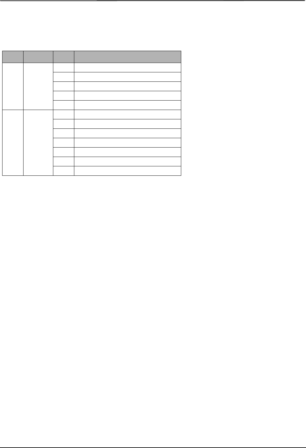
SMS Command and Control Response 3G Alarm Communicator Installlation Manual
22
[634] Error Code
Default (Error Code);
When an SMS initiated function fails, the module will send an error code to the telephone number that was source of the
SMS request. Message format is: [Account Label] [Date and Time] [Error Code] [Error Type]. Fields are “space” delimited.
Table 10: Error Code Format
Class Definition Error Definition
01 DLS
01 Bad SMS format
02 Session failed due to local network issues
03 Unable to connect to remote server
04 Bad DLS access code
05 DLS lockout active
02 TFTP
01 Bad SMS format
02 Session failed due to local network issues
03 Unable to connect to remote server
04 File not found on TFTP server
05 File not found on TFTP server
06 Update was unsuccessful
07 Update was successful

3G Alarm Communicator Installlation Manual System Information (Read Only)
23
RECEIVER DIAGNOSTIC TESTING
[901] Diagnostic Test Transmission
[1] Ethernet 1 (OFF).
[2] Ethernet 2 (OFF).
[3] Cellular 1 (OFF).
[4] Cellular 2 (OFF).
[5],[6],[7],[8] Reserved (OFF).
This Section may be used by the installer to force the Communicator to send an immediate test transmission to specific receivers, to
verify that the communications paths are available. Diagnostic Test Transmission failure will indicate as FTC trouble (Yellow LED = 9
flashes). If an FTC error occurs when testing all receivers, select only one receiver and repeat test to isolate the receiver that is not com-
municating.
SYSTEM INFORMATION (READ ONLY)
NOTE: Sections [987] - [998] are provided for information (Read Only). Values in these Sections can not be modified by the Installer.
[987] Language Version
This Section will display the current Language version of the Communicator.
[988] DNS 1 IP Address
This Section will display the IP address of DNS Server 1. This is useful when the unit is configured for DHCP and you need to see the
IP address was assigned to the device by the DHCP Server. This value is programmed in Section [007] or assigned by DHCP.
[989] DNS 2 IP Address
This Section will display the IP address of DNS Server 2. This is useful when the unit is configured for DHCP and you need to see the
IP address that was assigned to the device by the DHCP Server. This value is programmed in Section [008] or assigned by DHCP.
[990] Boot Loader Version
This Section will display the current Boot Loader version of the Communicator.
[991] Firmware Version
This Section will display the current firmware version of the device. Update worksheets with new version after a flash update is com-
pleted.
[992] Ethernet IP Address
This Section will display the IP address of the Ethernet connection. This value is programmed in Section [001] or assigned by DHCP.
[993] Ethernet Gateway Address
This Section will display the IP address of the Ethernet Gateway. This value is programmed in Section [003] or assigned by DHCP.
[994] Cellular IP Address
This Section will display the current dynamic IP address assigned by DHCP to the Cellular connection.
NOTE: Cellular uses DHCP (Dynamic IP) only. The Cellular IP address is always provided by the Cellular network (i.e., not program-
mable).
[995] SIM Number
This Section will display the Subscriber Identity Module (SIM) number of the SIM card installed in the Communicator. Format is:
Major Industry Identifier (2 digits) Mobile Country Code (2 or 3 digits); Mobile Network Code (2 - 3 digits); Unique Number (10 - 12
digits); and Checksum (1 digit). Valid SIM numbers range is: 18 - 21 numbers. This number is printed on SIM and the outside of the
Communicator carton.
NOTE: The Checksum digit is omitted on 19-digit SIM Card numbers.
[996] Cellular Telephone Number
NOTE: This Section will display the Cellular telephone number of the SIM. This telephone number is required by the Installer for DLS
and remote firmware (flash) update. User can access this telephone number by entering [*] [6] < > “Cellular Phone No.” to dis-
play the phone number.
[997] IMEI Number
This Section will display the unique 15-digit International Mobile Equipment Identity (IMEI) of the radio. Format is: Reporting Body
Identifier (2 digits), Allocation Number (4 digits); Final Assembly Code (2 digits); Serial Number (6 digits); and a check digit.
[998] MAC Address
This Section will display the unique12-digit, hexadecimal number assigned as the Media Access Control (MAC) address of the device.
SYSTEM RESET DEFAULTS
[999] Software Default
Default (99);
The Software default allows the installer to refresh the unit after changes and also return the Communicator to the default state.
00: Default Module. All programming Sections in module revert to factory settings. This will erase all existing programming of the
unit.
55: Reset. The Communicator is reset. This option is equivalent to power cycling the Communicator.
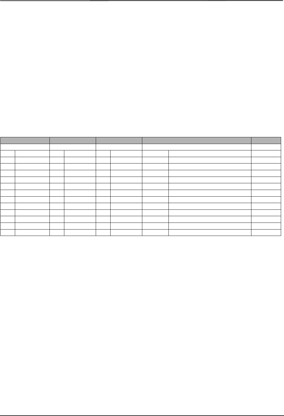
Communicator Status, Initialization, Diagnostics and Trou- 3G Alarm Communicator Installlation Manual
24
COMMUNICATOR STATUS, INITIALIZATION, DIAGNOSTICS AND TROUBLESHOOTING
[984] Communicator Status
The communicator status sections are intended to provide the installer with real-time status of the communicator’s functionality, opera-
tional readiness, failures, and potential malfunctions that may affect flawless operation of the communicator and its primary function of
sending signal to the central station in case the monitored event occurs.
The communicator status is displayed in the form of a 6-digit CODE (6 hexadecimal numbers) as in the following pattern: 00000F. The
range of the code is from: 00000F – 2220CF. Not all numbers in this range are assigned a status code (Some numbers are skipped, i.e.
not assigned the code).
Each digit represents a status or trouble indicator (or assigned function when no trouble is present) as described below:
1. Digit 1 - Signal Indicator 1, displays the presence/strength of signal 1.
2. Digit 2 - Signal Indicator 2, displays the presence/strength of signal 2.
3. Digit 3 - Network Indicator, displays the presence (operational status) of network.
4. Digit 4 & 5 – TROUBLE INDICATOR displays the type of problem/malfunction on communicator or modules associated with and
connected to communicator.
5. Digit 6 – Reserved for future use.
For example, status code 11002F – when interpreted means: “Signal Indicator 1 OK, Signal indicator 2 OK, there is no network trouble,
and there is trouble in the communicator, Panel supervision trouble.” For details see the table below:
Table 11: Communicator Status and Trouble Coding in Hexadecimal Numbers
The communicator status codes will indicate the signal levels with digit 1 and 2, a network status with digit 3, and the trouble status
with digit 4 and 5 as indicated in table above. For example status code 11000F would display following status:
1 – On = Signal indicator 1, is ON
1 – On = Signal indicator 2, is ON
0 – OFF = Network indicator, network is working
00 – TROUBLE INDICATOR = there is no trouble on the communicator.
F – Future code not assigned yet. It is sixth hexadecimal digit. It could be also ‘ - ‘ (dash) instead of letter F (11000-).
In this example both signal indicators are on indicating that communicator has excellent signal level; the network indicator is OFF
showing that we do no have any network problems and trouble indicators are both OFF indicating that we don’t have any trouble on the
communicator.
[985] Radio Initialization Status
The radio initialization status is intended to provide the installer with real-time status of radio communication. The radio initialization
status is displayed in an 8 bit toggle option. Each digit indicates one task in the radio initialization process as follows:
1. Radio power up
2. Receiving the SMS from C24
3. Radio reset
4. Radio attached to network
5. Receiver 1 Initialized
6. Receiver 2 Initialized
7. Receiver 3 Initialized
8. Receiver 4 Initialize
The following table shows each digit position in the status code, each digit’s value and its assigned meaning in the eight-digit code:
Digit 1 Digit 2 Digit 3 Digit 4 & 5 Digit 6
Signal indicator 1 Signal indicator 2 Network indicator TROUBLE INDICATOR Future use
0 Off 0 Off 0 Off 00 Off (No trouble) F
1 On 1 On 1 On 01 Future use F
2 Flashing 2 Flashing 2 Flashing 02 Panel supervision trouble F
03 Future use F
04 Lockout trouble F
05 3G/Cellular trouble F
06 Ethernet Trouble F
07 Receiver Not Available F
08 Receiver Supervision trouble F
09 FTC Trouble F
0A C24 Configuration SMS Failure F
0B Future use F
0C Module configuration Trouble F

3G Alarm Communicator Installlation Manual Communicator Status, Initialization, Diagnostics and Troubleshooting
25
For example, the radio initialization status code 12-45--- indicates that Radio has been powered up, it has received SMS signal from C24, the radio is
attached to the network, and Receiver 1 has been initialized. This code could be followed with...567 if Receivers 2, 3, and 4 are initialized where appli-
cable.
If the radio initialization status code does not indicate any problems, proceed with installation as per this manual. If troubles are reported, reset the ini-
tialization process. If this action does not fix the problem, refer to Trouble shooting section in this manual.
Table 13: Trouble Code Indications
Table 12: Radio Initialization Status - 1-8 bits completion
Bit 12345678
Not Completed --------
Completed 12345678
Trouble Indicator
Digit Possible Causes Trouble Possible Solutions
00 No Trouble N/A
02 Panel Supervision Trou-
ble
Check Section [382]Toggle Option[5] is ON (3G/Ethernet Module Enabled).
Ensure the PC-LINK cable between the Panel and Communicator is connected properly (not
reversed) and is securely in place.
04 Lockout Trouble The SIM card has incorrect PIN programmed or has a PIN that the module does not recognize.
Replace the SIM card.
05 3G/Cellular Trouble
Confirm that 3G service is available and active in your area.
Check all antenna connections.
Ensure average radio signal strength is CSQ 6 or higher. (See Table 7).
Ensure the SIM card is properly inserted into the SIM card holder.
Ensure the SIM card has been activated. (Could take up to 24 hrs after install).
If this trouble persists, relocate the Panel (and Communicator) or install an external antenna
extension kit.
06 Ethernet Trouble
Check with your ISP to confirm Internet service is active in your area.
Ensure your Ethernet cable is securely inserted into the RJ45 jack of the Communicator and the
Hub/Router/ Switch.
Check that the link light on the Hub/Router/ Switch is ON. If link light is OFF, try restarting the
Hub/Router/ Switch.
If DHCP is used, ensure that the unit has an assigned IP address from the server.
In Section [851] [992] verify a valid IP address is programmed. If not, contact the Network
administrator.
If problem persists, replace the Ethernet cable and RJ45 connector.
07 Receiver Not Available
Ensure that the Ethernet path has internet connectivity.
If you are using a static IP address make sure the gateway and subnet mask are entered correctly.
If the network has a firewall, ensure the network has the programmed outgoing ports open
(Default UDP Port 3060 and Port 3065).
Ensure that all the receivers are programmed for DHCP or have the proper IP address and port
number.
Ensure the 3G Receiver APNs have been programmed with the Access Point Name provided by
your 3G provider.
08 Receiver Supervision
Trouble
This trouble is indicated when supervision is enabled and the unit is not able to successfully
communicate with the receiver.
If this trouble persists, contact your central station.
09 FTC Trouble The unit has exhausted all communications attempts to all programmed receivers for events gen-
erated by the Communicator.
Restart the system. If trouble persists, contact your dealer.
0A Connect24 Configura-
tion Failure
The SIM is active but there is no programming for the Communicator.
Ensure a profile has been programmed in Connect-24 for the SIM.
You can confirm your programming by calling the Connect-24 VRU, or by logging into the
Connect24 VRU web site.
0C Module Configuration
Trouble
This indication appears when Section [021] System Account Code, Section [101], [111], [201],
and [211] Receiver Account Code have not been programmed. Ensure that a valid account code
has been entered in these Sections.
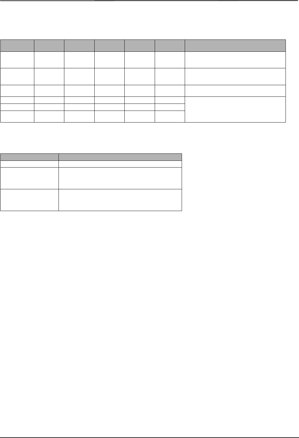
Communicator Status, Initialization, Diagnostics and Trou- 3G Alarm Communicator Installlation Manual
26
Communicator Troubleshooting
The status code for the radio signal strength, its typical troubles, possible causes and troubleshooting instructions is displayed in the table below.
Table 14: Radio Signal Strength
The table below displays the Network indicator codes and meaning of each code.
Table 15: Network indicator - Digit 3
Signal
Strength CSQ Level Signal
Indicator 1 Signal
Indicator 2 Signal Level
[dBm] Signal Level
Status Action Required
No Signal 0 0 0 -108.8 bad Check all antenna connections.
Confirm 3G service is active in area.
Relocate Panel or install external antenna.
1 Bar 1 - 4 0 2 -108 ~ -103 weak Relocate Panel or install external antenna if Yel-
low Trouble LED has:
5 flashes.
2 Bars 5 - 6 0 1 -102 ~ -99 normal/
acceptable
3 Bars 7 - 10 2 1 -98 ~ -91 strong
Location is OK. 3G Signal Strength is greater
than CSQ 5.
4 Bars 11 - 13 2 1 -90 ~ -85 strong
5 Bars 14 + 1 1 -84 and
higher excellent
Network indicator Value Means
OFF No Network Trouble
ON
Ethernet Cable disconnected
Ethernet DHCP failed
Radio connection has been rest
Radio IP failed
Flashing
Incoming transmission
Connect 24 programming
Outgoing transmission
Incoming transmission

3G Alarm Communicator Installlation Manual Communicator Status, Initialization, Diagnostics and Troubleshooting
27
Firmware Update Diagnostics Section
The firmware updates can be made from communicator. Communicator can update firmware of the panel and also of communicator itself.
• The Firmware Update Diagnostic is located in section [984]
The Firmware Update Diagnostic section shall be a Read Only 2 Digit, Hexadecimal Section
• From Factory Default, the value of this Location shall be 0xFE which indicates No Errors, when a default is made, Diagnostic Section shall default
to 0xFE
• Communicator could reject Firmware Download SMS String for many reasons, this will only be represented as 1 Reason Code 0xFF Described as
Firmware Receive Failure (The detailed reasons why this occurred will be captured in the manual) Firmware Receive Failure may be rejected of the fol-
lowing conditions:
• DLS Session in Progress
• C24 Programming in Progress
• Remote Firmware Upgrade is Disabled
• TFTP Firmware Update Download is in Progress
• iControl/iHub Firmware Update in Progress
• Panel Update in Progress
• Once file download has begin, Section [984] shall be updated with 0xFD
• If the download was dropped/cancelled for any reason, section [984] shall update it with 0xFF
• Upon Download successful, the communicator will either be updating itself, or the panel
• In the case of Communicator Firmware Upgrade, the communicator shall enter a 4.5 minute window before it performs the update because it is
communicating to Central Station and interactive services. Section [984] shall use reason code 0x0A indicating communication in progress at this point
• In the case of Panel Firmware Update, if panel firmware pushes through, User will be able to observe it because the keypad enters keybus fault. If
panel rejects firmware for any reason, the communicator shall update section [984] with the cancellation reason code provided by the panel
• In the Case of Communicator Firmware Update successful, the communicator shall update diagnostic section to 0xFB after it is updated success-
fully
• During Panel Firmware Update Sequence, the Panel could Cancel the Firmware Update due to the Following Reasons Codes:
• Panel does not Send any Reason Code Upon Success of Panel Firmware Upgrade, section [984] shall be updated with 0xFC to indicate Panel
Firmware Update Complete.
Reason codes and corresponding firmware images are displayed in the table below.
Table 16: Reason Codes Description and Corresponding Firmware Images
The table below displays the Network indicator codes and meaning of each code.
The firmware updates can be made from communicator. Communicator can update firmware of the panel and also of communicator itself.
• This section does not provide specific details such as if the Image is still stored or erased due to the cancellation code. Specific details shall be cap-
tured in User/Installation Manuals and provided to Technical Advice Bulletin
• For the Purpose of Documentation:
• Communicator shall erase panel image file on Reason Code 0x00 ~ 0x04 and 0x0B
• Communicator shall try to upgrade panel image file forever on Reason Code 0x05 ~ 0x0A.
Reason Code Description of Reason Code Firmware Image is
00 Version Check Failed Image Erased
01 Image Type Mismatch Image Erased
02 Panel Type Mismatch Image Erased
03 Hardware Type Mismatch Image Erased
04 Firmware header Wrong Length Image Erased
05 Panel is Armed Firmware Update Pending Status Clearnace
06 AC Trouble Firmware Update Pending Status Clearnace
07 Low Battery Firmware Update Pending Status Clearnace
08 Unviewed Alarm Firmware Update Pending Status Clearnace
09 FTC Trouble Firmware Update Pending Status Clearnace
0A Communication in Progress Firmware Update Pending Status Clearnace
0B Software Variant Mismatch Image Erased
FA (Future Use) (Future Use)
FB Communicator Firware Update Complete
FC Panel Firmware Update Complete
FD File Download in Progress
FE Firmware File Empty Software Default Value (Factory Default)
FF File Receive Failure File Was Not Received

Communicator Status, Initialization, Diagnostics and Trou- 3G Alarm Communicator Installlation Manual
28

3G Alarm Communicator Installlation Manual System Options
29
SYSTEM OPTIONS
[001] Ethernet IP Address
Default (000.000.000.000)
|____|____|____||____|____|____||____|____|____|____|____|____|
[002] Ethernet IP Subnet Mask
Default (255.255.255.000)
|____|____|____||____|____|____||____|____|____|____|____|____|
[003] Ethernet Gateway IP Address
Default (000.000.000.000)
|____|____|____||____|____|____||____|____|____|____|____|____|
[004] Receiver Supervision Interval
Default (0087/135) Valid range: 0000 - FFFF.
|____|____|____|____|
[005] System Toggle Options
|____| [1] Ethernet Receiver 1 Supervised Default (OFF).
|____| [2] Cellular Receiver 1 Supervised Default (OFF).
|____| [3] Supervision Type Default (OFF).
|____| [4] Primary Communications Path.
Default [OFF] TL260R; [ON]3G2060R.
|____| [5] Redundant Communications Default (OFF).
|____| [6] Remote Firmware Upgrade Default (ON).
|____| [7] Alternate Test Transmission Default (OFF).
|____| [8] Cellular Low Signal Trouble Default (OFF).
[006] System Toggle Options 2
|____| [1] Ethernet Receiver 1 Enabled Default (ON).
|____| [2] Ethernet Receiver 2 Enabled Default (ON).
|____| [4] Cellular Receiver 1 Enabled Default (ON).
|____| [5] Cellular Receiver 2 Enabled Default (ON).
|____| [7] DLS Over Cellular Default (ON).
|____| [8] Interactive Over Cellular Default (ON).
[007] DNS Server IP 1
Programming not permitted on UL/ULC listed system.
Default (000.000.000.000)
|____|____|____||____|____|____||____|____|____|____|____|____|
[008] DNS Server IP 2
Programming not permitted on UL/ULC listed system.
Default (000.000.000.000)
|____|____|____||____|____|____||____|____|____|____|____|____|
PROGRAMMING OPTIONS
[010] System Toggle Option
Default (CAFE) Valid range: 0000 - FFFF.
|____|____|____|____|
[011] Installer Code
Default (CAFE) Valid range: 0000 - FFFF.
|____|____|____|____|
[012] DLS Incoming Port
Default (0BF6/3062) Valid range: 0000 - FFFF.
|____|____|____|____|
[013] DLS Outgoing Port
Default (0BFA/3066) Valid range: 0000 - FFFF.
|____|____|____|____|
[020] Time Zone
Default (CAFE) Valid range: 0000 - FFFF.
|____|____|____|____|
[022] Communications Format
Default (04) Program 03 (CID), 04 (SIA).
|____|____|
[023] Panel Absent Trouble
Default (FF); Program 00 disable or FF enable.
|____|____|
[024] Panel Absent Trouble Restore
Default (FF) Program 00 disable or FF enable.
|____|____|
[025] Radio Activation Restore
Default (FF) Program 00 disable or FF enable.
|____|____|
SYSTEM TEST OPTIONS [026 - 029]
[026] Ethernet 1 Transmission
Default (FF) Program 00 disable or FF enable.
|____|____|
[027] Ethernet 2 Transmission
Default (00) Program 00 disable or FF enable.
|____|____|
[028] Cellular 1 Transmission
Default (FF) Program 00 disable or FF enable.
|____|____|
[029] Cellular 2 Transmission
Default (00) Program 00 disable or FF enable.
|____|____|
[030] FTC Restore
Default (FF) Program 00 disable or FF enable.
|____|____|
[033] Communicator Firmware Update Begin
Default (FF) Program 00 disable or FF enable.
|____|____|
[034] Communicator Firmware Update Successful
Default (FF) Program 00 disable or FF enable.
|____|____|
[035] Panel Firmware Update Begin
Default (FF) Program 00 disable or FF enable.
|____|____|
[036] Panel Firmware Update Successful
Default (FF) Program 00 disable or FF enable.
|____|____|
[037] Panel Firmware Update Fail
Default (FF) Program 00 disable or FF enable.
|____|____|
ETHERNET/CELLULAR PROGRAMMING WORKSHEETS

Ethernet Receiver 1 Options 3G Alarm Communicator Installlation Manual
30
ETHERNET RECEIVER 1 OPTIONS
[101] Ethernet Receiver 1 Account Code
Default (0000000000)
Valid range: 0000000001 - FFFFFFFFFE.
|____|____|____|____|____|____|____|____|____|____|
[102] Ethernet Receiver 1 DNIS
Default (000000) Valid range: 000000 - FFFFFF.
|____|____|____|____|____|____|
[103] Ethernet Receiver 1 Address
Default (127.000.000.001)
|____|____|____||____|____|____||____|____|____|____|____|____|
[104] Ethernet Receiver 1 Remote Port
Default (0BF5/3061) Valid range: 0000 - FFFF.
|____|____|____|____|
[105] Ethernet Receiver 1 Local Port
Default (0BF4/3060)Valid range: 0000 - FFFF.
|____|____|____|____|
[106] Ethernet Receiver 1 Domain Name
Default ( ) 32 ASCII characters.
Programming not permitted on UL/ULC listed system.
________________________________
ETHERNET RECEIVER 2 OPTIONS
[111] Ethernet Receiver 2 Account Code
Default (0000000000)
Valid range: 0000000001 - FFFFFFFFFE.
|____|____|____|____|____|____|____|____|____|____|
[112] Ethernet Receiver 2 DNIS
Default (000000) Valid range: 000000 - 0FFFFF.
|____|____|____|____|____|____|
[113] Ethernet Receiver 2 Address
Default (000.000.000.000)
|____|____|____||____|____|____||____|____|____|____|____|____|
[114] Ethernet Receiver 2 Remote Port
Default (0BF5/3061) Valid range: 0000 - FFFF.
|____|____|____|____|
[115] Ethernet Receiver 2 Local Port
Default (0BF9/3065) Valid range: 0000 -FFFF.
|____|____|____|____|
[116] Ethernet Receiver 2 Domain Name
Default ( )
Programming not permitted on UL/ULC listed system.
____________________________________
ETHERNET OPTIONS
[124] Ethernet Test Transmission Time
Default (9999) Valid: 00-23(HH); 00-59(MM)
|____|____|____|____|
[125] Ethernet Test Transmission Cycle
Default (000000)
Valid range: 000000 - 999999 minutes.
|____|____|____|____|____|____|
CELLULAR RECEIVER 1 OPTIONS
[201] Cellular Receiver 1 Account Code
Default (0000000000)
Valid range: 0000000001 - FFFFFFFFFE.
|____|____|____|____|____|____|____|____|____|____|
[202] Cellular Receiver 1 DNIS
Default (000000) Valid range: 000000 - 0FFFFF.
|____|____|____|____|____|____|
[203] Cellular Receiver 1 Address
Default (000.000.000.000). Valid range: 000-255.
|____|____|____||____|____|____||____|____|____|____|____|____|
[204] Cellular Receiver 1 Port
Default (0BF5/3061) Valid range: 0000 - FFFF.
|____|____|____|____|
[205] Cellular Receiver 1 APN Default ( )
32 ASCII characters.
____________________________________

3G Alarm Communicator Installlation Manual Cellular Receiver 2 Options
31
[206] Cellular Receiver 1 Domain Name
Default ( )
Programming not permitted on UL/ULC listed system.
32 Character ASCII characters.
____________________________________
CELLULAR RECEIVER 2 OPTIONS
[211] Cellular Receiver 2 Account Code
Default (0000000000)
Valid range: 0000000001 - FFFFFFFFFE.
|____|____|____|____|____|____|____|____|____|____|
[212] Cellular Receiver 2 DNIS
Default (000000)
Valid range: 000000 - 0FFFFF.
|____|____|____|____|____|____|
[213] Cellular Receiver 2 Address
Default (000.000.000.000)
Valid segment range: 000-255
|____|____|____||____|____|____||____|____|____|____|____|____|
[214] Cellular Receiver 2 Port
Default (0BF5/3061) Valid range: 0000 - FFFF.
|____|____|____|____|
[215] Cellular Receiver 2 APN
Default ( ) 32 ASCII characters.
____________________________________
[216] Cellular Receiver 2 Domain Name
Default ( )
Programming not permitted on UL/ULC listed system.
32 ASCII characters.
____________________________________
CELLULAR OPTIONS
[221] Cellular Public Access Point Name
Default ( ) 32 ASCII characters
____________________________________
[222] Cellular Login User Name
Default ( ) 32 ASCII characters.
____________________________________
[223] Cellular Login Password
Default ( ) 32 ASCII characters.
____________________________________
[224] Cellular Test Transmission Time of Day
Default (9999) Valid range: 00 - 23 hrs. (HH) 00 - 59 min. (MM).
|____|____|____|____
[225] Cellular Test Transmission Cycle
Default (000000)
Valid range: 000000 - 999999 minutes.
|____|____|____|____|____|____|
[226] Cellular Trouble Delay
Default (00)
Program 00 disable or FF enable.
|____|____|
[301] Command and Control Toggle Options
|____| [1] Reserved Default ( )
|____| [2] Reserved Default ( )
|____| [3] SMS Command and Control Default (ON).
|____| [4] Reserved Default ( )
|____| [5] SMS Character Format
|____| [6] Long SMS Message Handling Default (OFF)
|____| [7] Reserved Default ( )
|____| [8] Reserved Default ( )
[311] - [318] SMS Phone Number 1 - 8
This section may be programmed through DLS IV or the keypad.
____________________________________
[321] - [328] SMS Phone Number 1 - 8 Toggle Options
|____| [1] SMS Notification Alarm/Restore Default (OFF)
|____| [2] SMS Notification Tamper/Restore Default (OFF)
|____| [3] SMS Notification Opening/Closing Default (OFF)
|____| [4] SMS Notification System Maintenance Default (OFF)
|____| [5] SMS Notification System Test Default (OFF)
|____| [6] SMS Notification Internal Events Default (OFF)
|____| [7] SMS Notification Enabled Default (OFF)
|____| [8] SMS Command and Control Enabled Default (ON)
[601] Stay Arm
Default (Stay Arm);
Send this command to the system to stay arm.
____________________________________
[602] Away Arm
Default (Away Arm);
Send this command to the system to away arm.
____________________________________
[603] Night Arm
Default (Night Arm);
Send this command to the system to night arm.
____________________________________
[604] Disarm
Default (Disarm);
Send this command to the system to night disarm.
____________________________________
[605] - [608] Activate Command Output 1 - 4
Default (Activate Command Output n);
Send this command to the system to activate a command output.
____________________________________
[609] - [612] Deactivate Command Output 1 - 4
Default (Deactivate Command Output n);
Send this command to the system to deactivate a command output.
____________________________________
[613] Bypass
Default (Bypass);
Send this command to the system to bypass a Zone.
____________________________________
[614] Unbypass
Default (Unbypass);
Send this command to the system to unbypass a Zone.
____________________________________

3G Alarm Communicator Installlation Manual
32
[615] Status Request
Default (Status Request);
Send this command to request the status of the system.
____________________________________
[616] Alarm Memory Request
Default (Alarm Memory Request);
Send this command to request the alarm memory from the system.
____________________________________
[617] Help
Default (Help);
Access Code is not required.
____________________________________
[621] Function Successful
Default (Successful);
Example: “stay armed successful.”
____________________________________
[622] Function Unsuccessful
Default (Unsuccessful);
Example: “stay armed unsuccessful.”
____________________________________
[623] Invalid Command
Default (Invalid Command);
Unprogrammable, enter correct command.
____________________________________
[624] System Stay Armed
Default (Stay Arm);
Included in the response message if the command was not accepted as a
valid SMS command.
____________________________________
[625] System Away Armed
Default (Away Arm);
Included in the response to a status request command if a partition is
away armed.
____________________________________
[626] System Night Armed
Default (Night Arm);
Included in the response to a status request command if a partition is night
armed.
____________________________________
[627] System Disarmed Ready
Default (Disarmed Ready);
Included in the response to a status request command if a partition is dis-
armed and is ready to arm.
____________________________________
[628] System Disarmed Not Ready
Default (Disarmed Not Ready);
Included in the response to a status request command if a partition is dis-
armed and is not ready to arm.
____________________________________
[629] System is in Alarm
Default (Stay Arm);
This label will be included in the response to an Alarm Memory Request
if there are no alarms on the system
____________________________________
[630] Trouble Label
Default (Service is Required);
Included in the response to the Alarm Memory command if there are no
alarms in memory.
____________________________________
[631] No Alarms in Memory
Default (No Alarm Memory);
Included in the response to the Alarm Memory command if there are no
alarms on the system.
____________________________________
[634] Error Code
Default (Error Code);
Included in the response to an Alarm Memory Request if there are no
alarms on the system
____________________________________

3G Alarm Communicator Installlation Manual System Information (Read Only)
33
[901] Diagnostic Test Transmission
|___| [1] Ethernet 1 Default (OFF).
|___| [2] Ethernet 2 Default (OFF).
|___| [3] Cellular 1 Default (OFF).
|___| [4] Cellular 2 Default (OFF).
SYSTEM INFORMATION (READ ONLY)
[988] DNS 1 IP Address
|____|____|____||____|____|____||____|____|____|____|____|____|
[989] DNS 2 IP Address
|____|____|____||____|____|____||____|____|____|____|____|____|
[991] Firmware Version
|____|____|____|____|____|____|____|____|
[992] Ethernet IP Address
|____|____|____||____|____|____||____|____|____|____|____|____|
[993] Ethernet Gateway Address
|____|____|____||____|____|____||____|____|____|____|____|____|
[994] Cellular IP Address
|____|____|____||____|____|____||____|____|____|____|____|____|
[995] SIM Number
____________________________________
[996] Cellular Telephone Number
This number is required for DLS, and Firmware upgrades.
____________________________________
[997] IMEI Number
____________________________________
[998] MAC Address
|____|____|____|____|____|____| |____|____|____|____|____|____|
SYSTEM RESET DEFAULTS
[999] Software Default
Default (99); Valid entries are 00 or 55
|____|____|

End User Licence Agreement 3G Alarm Communicator Installlation Manual
34
END USER LICENCE AGREEMENT
IMPORTANT - READ CAREFULLY: DSC Software purchased with or without Products and Components is Copyrighted and is pur-
chased under the following license terms:
This End-User License Agreement (EULA) is a legal agreement between You (the
company, individual or entity who acquired the SOFTWARE and any related
HARDWARE) and Digital Security Controls (DSC), a division of Tyco Safety
Products Canada Ltd., the manufacturer of the integrated security systems and the
developer of the software and any related products or components (‘HARD-
WARE’) which you acquired.
If the DSC software product (‘SOFTWARE PRODUCT’ or ‘SOFTWARE’) is
intended to be accompanied by HARDWARE, and is NOT accompanied by new
HARDWARE, You may not use, copy or install the SOFTWARE PRODUCT. The
SOFTWARE PRODUCT includes computer software, and may include associated
media, printed materials, and ‘online’ or electronic documentation.
Any software provided along with the SOFTWARE PRODUCT that is associated
with a separate EULA is licensed to You under the terms of that license agreement.
By installing, copying, downloading, storing, accessing, or otherwise using the
SOFTWARE PRODUCT, You agree unconditionally to be bound by the terms of
this EULA, even if this EULA is deemed to be a modification of any previous
arrangement or contract. If You do not agree to the terms of this EULA, DSC is
unwilling to license the SOFTWARE PRODUCT to You, and You have no right to
use it.
SOFTWARE PRODUCT LICENSE
The SOFTWARE PRODUCT is protected by copyright laws and international
copyright treaties, as well as other intellectual property laws and treaties. The
SOFTWARE PRODUCT is licensed, not sold, under the following terms:.
GRANT OF LICENSE This EULA grants You the following rights:
Software Installation and Use - For each license You acquire, You may have only
one copy of the SOFTWARE PRODUCT installed.
Storage/Network Use - The SOFTWARE PRODUCT may not be installed,
accessed, displayed, run, shared or used concurrently on or from different comput-
ers, including a workstation, terminal or other digital electronic device (‘Device’).
In other words, if You have several workstations, You will have to acquire a license
for each workstation where the SOFTWARE will be used.
Backup Copy - You may make back-up copies of the SOFTWARE PRODUCT,
but You may only have one copy per license installed at any given time. You may
use the back-up copy solely for archival purposes. Except as expressly provided in
this EULA, You may not otherwise make copies of the SOFTWARE PRODUCT,
including the printed materials accompanying the SOFTWARE.
DESCRIPTION OF OTHER RIGHTS AND LIMITATIONS
Limitations on Reverse Engineering, Decompilation and Disassembly - You
may not reverse engineer, decompile, or disassemble the SOFTWARE PRODUCT,
except and only to the extent that such activity is expressly permitted by applicable
law notwithstanding this limitation. You may not make any changes or modifica-
tions to the Software, without the written permission of an officer of DSC. You may
not remove any proprietary notices, marks or labels from the Software Product.
You shall institute reasonable measures to ensure compliance with the terms and
conditions of this EULA.
Separation of Components - The SOFTWARE PRODUCT is licensed as a single
product. Its component parts may not be separated for use on more than one
HARDWARE unit.
Single INTEGRATED PRODUCT - If You acquired this SOFTWARE with
HARDWARE, then the SOFTWARE PRODUCT is licensed with the HARD-
WARE as a single integrated product. In this case, the SOFTWARE PRODUCT
may only be used with the HARDWARE as set forth in this EULA.
Rental - You may not rent, lease or lend the SOFTWARE PRODUCT. You may
not make it available to others or post it on a server or web site.
Software Product Transfer - You may transfer all of Your rights under this EULA
only as part of a permanent sale or transfer of the HARDWARE, provided You
retain no copies, You transfer all of the SOFTWARE PRODUCT (including all
component parts, the media and printed materials, any upgrades and this EULA),
and provided the recipient agrees to the terms of this EULA. If the SOFTWARE
PRODUCT is an upgrade, any transfer must also include all prior versions of the
SOFTWARE PRODUCT.
Termination - Without prejudice to any other rights, DSC may terminate this
EULA if You fail to comply with the terms and conditions of this EULA. In such
event, You must destroy all copies of the SOFTWARE PRODUCT and all of its
component parts.
Trademarks - This EULA does not grant You any rights in connection with any
trademarks or service marks of DSC or its suppliers.
COPYRIGHT - All title and intellectual property rights in and to the SOFTWARE
PRODUCT (including but not limited to any images, photographs, and text incor-
porated into the SOFTWARE PRODUCT), the accompanying printed materials,
and any copies of the SOFTWARE PRODUCT, are owned by DSC or its suppliers.
You may not copy the printed materials accompanying the SOFTWARE PROD-
UCT. All title and intellectual property rights in and to the content which may be
accessed through use of the SOFTWARE PRODUCT are the property of the
respective content owner and may be protected by applicable copyright or other
intellectual property laws and treaties. This EULA grants You no rights to use such
content. All rights not expressly granted under this EULA are reserved by DSC and
its suppliers.
EXPORT RESTRICTIONS - You agree that You will not export or reexport the
SOFTWARE PRODUCT to any country, person, or entity subject to Canadian
export restrictions.
CHOICE OF LAW - This Software License Agreement is governed by the laws
of the Province of Ontario, Canada.
ARBITRATION - All disputes arising in connection with this Agreement shall be
determined by final and binding arbitration in accordance with the Arbitration Act,
and the parties agree to be bound by the arbitrator’s decision. The place of arbitra-
tion shall be Toronto, Canada, and the language of the arbitration shall be English.
7. LIMITED WARRANTY
NO WARRANTY - DSC provides the SOFTWARE ‘as is’ without warranty. DSC
does not warrant that the SOFTWARE will meet your requirements or that opera-
tion of the SOFTWARE will be uninterrupted or error free.
CHANGES IN OPERATING ENVIRONMENT - DSC shall not be responsible
for problems caused by changes in the operating characteristics of the hardware, or
for problems in the interaction of the SOFTWARE with non DSC software or hard-
ware products.
LIMITATION OF LIABILITY; WARRANTY REFLECTS ALLOCATION
OF RISK -In any event, if any statute implies warranties or conditions not stated
in this license agreement, entire liability under any provision of this license agree-
ment shall be limited to the greater of the amount actually paid by you to license the
SOFTWARE and five Canadian dollars (CAD$5.00). because some jurisdictions
do not allow the exclusion or limitation of liability for consequential or incidental
damages, the above limitation may not apply to you.
DISCLAIMER OF WARRANTIES - This warranty contains the entire warranty
and shall be in lieu of any and all other warranties, whether expressed or implied
(including all implied warranties of merchantability or fitness for a particular pur-
pose) and of all other obligations or liabilities on the part of DSC. DSC makes no
other warranties. DSC neither assumes nor authorizes any other person purporting
to act on its behalf to modify or to change this warranty, nor to assume for it any
other warranty or liability concerning this SOFTWARE PRODUCT.
EXCLUSIVE REMEDY AND LIMITATION OF WARRANTY - Under no
circumstances shall DSC be liable for any special, incidental, consequential or indi-
rect damages based upon breach of warranty, breach of contract, negligence, strict
liability, or any other legal theory. such damages include, but are not limited to, loss
of profits, loss of the SOFTWARE or any associated equipment, cost of capital,
cost of substitute or replacement equipment, facilities or services, down time, pur-
chasers time, the claims of third parties, including customers, and injury to prop-
erty.
DSC recommends that the entire system be completely tested on a regular basis.
However, despite frequent testing, and due to, but not limited to, criminal tamper-
ing or electrical disruption, it is possible for this Software Product to fail to perform
as expected.

3G Alarm Communicator Installlation Manual Limited Warranty
35
LIMITED WARRANTY
Digital Security Controls (DSC) warrants the original purchaser
that for a period of twelve (12) months from the date of purchase,
the product shall be free of defects in materials and workmanship
under normal use. During the warranty period, Digital Security
Controls shall, at its option, repair or replace any defective prod-
uct upon return of the product to its factory, at no charge for
labour and materials. Any replacement and/or repaired parts are
warranted for the remainder of the original warranty or ninety
(90) days, whichever is longer. The original purchaser must
promptly notify Digital Security Controls in writing that there is
defect in material or workmanship, such written notice to be
received in all events prior to expiration of the warranty period.
There is absolutely no warranty on software and all software
products are sold as a user license under the terms of the software
license agreement included with the product. The Customer
assumes all responsibility for the proper selection, installation,
operation and maintenance of any products purchased from DSC.
Custom products are only warranted to the extent that they do not
function upon delivery. In such cases, DSC can replace or credit at
its option.
International Warranty
The warranty for international customers is the same as for any
customer within Canada and the United States, with the exception
that Digital Security Controls shall not be responsible for any cus-
toms fees, taxes, or VAT that may be due.
Warranty Procedure
To obtain service under this warranty, please return the item(s) in
question to the point of purchase. All authorized distributors and
dealers have a warranty program. Anyone returning goods to Dig-
ital Security Controls must first obtain an authorization number.
Digital Security Controls will not accept any shipment whatso-
ever for which prior authorization has not been obtained.
Conditions to Void Warranty
This warranty applies only to defects in parts and workmanship
relating to normal use. It does not cover:
• damage incurred in shipping or handling;
• damage caused by disaster such as fire, flood, wind, earthquake
or lightning;
• damage due to causes beyond the control of Digital Security
Controls such as excessive voltage, mechanical shock or water
damage;
• damage caused by unauthorized attachment, alterations, modi-
fications, or foreign objects;
• damage caused by peripherals (unless such peripherals were
supplied by Digital Security Controls);
• defects caused by failure to provide a suitable installation envi-
ronment for the products;
• damage caused by use of the products for purposes other than
those for which it was designed;
• damage from improper maintenance; or
• damage arising out of any other abuse, mishandling or
improper application of the products.
Items Not Covered by Warranty
In addition to the items which void the Warranty, the following
items shall not be covered by Warranty:
freight cost to the repair centre;
products which are not identified with DSC's product label and lot
number or serial number; or
products disassembled or repaired in such a manner as to
adversely affect performance or prevent adequate inspection or
testing to verify any warranty claim.
Access cards or tags returned for replacement under warranty will
be credited or replaced at DSC's option. Products not covered by
this warranty, or otherwise out of warranty due to age, misuse, or
damage shall be evaluated, and a repair estimate shall be pro-
vided. No repair work will be performed until a valid purchase
order is received from the Customer and a Return Merchandise
Authorisation number (RMA) is issued by DSC's Customer Ser-
vice.
Digital Security Controls’ liability for failure to repair the product
under this warranty after a reasonable number of attempts will be
limited to a replacement of the product, as the exclusive remedy
for breach of warranty. Under no circumstances shall Digital
Security Controls be liable for any special, incidental, or conse-
quential damages based upon breach of warranty, breach of con-
tract, negligence, strict liability, or any other legal theory. Such
damages include, but are not limited to, loss of profits, loss of the
product or any associated equipment, cost of capital, cost of sub-
stitute or replacement equipment, facilities or services, down
time, purchaser’s time, the claims of third parties, including cus-
tomers, and injury to property. The laws of some jurisdictions
limit or do not allow the disclaimer of consequential damages. If
the laws of such a jurisdiction apply to any claim by or against
DSC, the limitations and disclaimers contained here shall be to the
greatest extent permitted by law. Some states do not allow the
exclusion or limitation of incidental or consequential damages, so
that the above may not apply to you.
Disclaimer of Warranties
This warranty contains the entire warranty and shall be in lieu of
any and all other warranties, whether expressed or implied
(including all implied warranties of merchantability or fitness for
a particular purpose) and of all other obligations or liabilities on
the part of Digital Security Controls Digital Security Controls nei-
ther assumes responsibility for nor authorizes any other person
purporting to act on its behalf to modify or to change this war-
ranty, nor to assume for it any other warranty or liability concern-
ing this product.
This disclaimer of warranties and limited warranty are governed
by the laws of the province of Ontario, Canada.
Digital Security Controls recommends that the entire system be
completely tested on a regular basis. However, despite frequent
testing, and due to, but not limited to, criminal tampering or elec-
trical disruption, it is possible for this product to fail to perform as
expected.
Out of Warranty Repairs
Digital Security Controls will at its option repair or replace out-
of-warranty products which are returned to its factory according
to the following conditions. Anyone returning goods to Digital
Security Controls must first obtain an authorization number. Digi-
tal Security Controls will not accept any shipment whatsoever for
which prior authorization has not been obtained.
Products which Digital Security Controls determines to be repair-
able will be repaired and returned. A set fee which Digital Secu-
rity Controls has predetermined and which may be revised from
time to time, will be charged for each unit repaired.

FCC Compliance Statement
CAUTION: Changes or modifications not expressly approved by the Digital Security Controls could void
your authority to use this equipment.
This equipment has been tested and found to comply with the limits for a Class B digital device, pursuant to Part 15 of the FCC Rules.
These limits are designed to provide reasonable protection against harmful interference in a residential installation. This equipment
generates, uses and can radiate radio frequency energy and, if not installed and used in accordance with the instructions, may cause
harmful interference to radio communications. However, there is no guarantee that interference will not occur in a particular installa-
tion. If this equipment does cause harmful interference to radio or television reception, which can be determined by turning the equip-
ment off and on, the user is encouraged to try to correct the interference by one or more of the following measures:
- Re-orient the receiving antenna.
- Increase the separation between the equipment and receiver.
- Connect the equipment into an outlet on a circuit different from that to which the receiver is connected.
- Consult the dealer or an experienced radio/television technician for help.
The user may find the following booklet prepared by the FCC useful: ‘How to Identify and Resolve Radio/Television Interference
Problems’. This booklet is available from the U.S. Government Printing Office, Washington D.C. 20402, Stock # 004-000-00345-4.
WARNING: TO SATISFY FCC RF EXPOSURE REQUIREMENTS FOR MOBILE TRANSMITTING DEVICES, A SEPARATION DIS-
TANCE OF 20CM OR MORE MUST BE MAINTAINED BETWEEN THE ANTENNA OF THIS DEVICE AND PERSONS DURING DEVICE
OPERATION.
Industry Canada Statement
The prefix ‘IC:’ in front of the radio certification number signifies only that Industry Canada technical specifications were met.
Certification Number IC: 160A-3G260R
This device complies with Industry Canada licence-exempt RSS standard(s). Operation is subject to the following tow conditions: (1)
this device may not cause interference, and (2) this device must accept any interference, including interference that may cause unde-
sired operation of the device.
Cet appareil est conforme avec Industrie Canada exempts de licence standard RSS (s). Le fonctionnement est soumis aux deux condi-
tions suivantes: (1) cet appareil ne peut pas provoquer d'interférences et (2) cet appareil doit accepter toute interférence, y compris les
interferences qui peuvent causer un mauvais fonctionnement de l'appareil.
This Class B digital apparatus complies with Canadian ICES-003.
Cet appareil numérique de la classe B est conforme à la norme NMB-003 du Canada.
© 2012 Tyco International Ltd. and its Respective Companies. All Rights Reserved.
Toronto, Canada · www.dsc.com
Tech Support: 1-800-387-3630 (CA, US), 905-760-3000
Printed in Canada