Tyco Safety Canada 15TL2553GRE Cellular alarm communicator with 2G/3G wireless module User Manual My
Digital Security Controls Ltd. Cellular alarm communicator with 2G/3G wireless module My
UserManual.wiki
>
Tyco Safety Canada
>
15TL2553GRE User Manual
User Manual
Navigation menu
Upload a User Manual
Namespaces
Wiki Guide
HTML
PDF
Info
Views
User Manual
Discussion / Help
Navigation
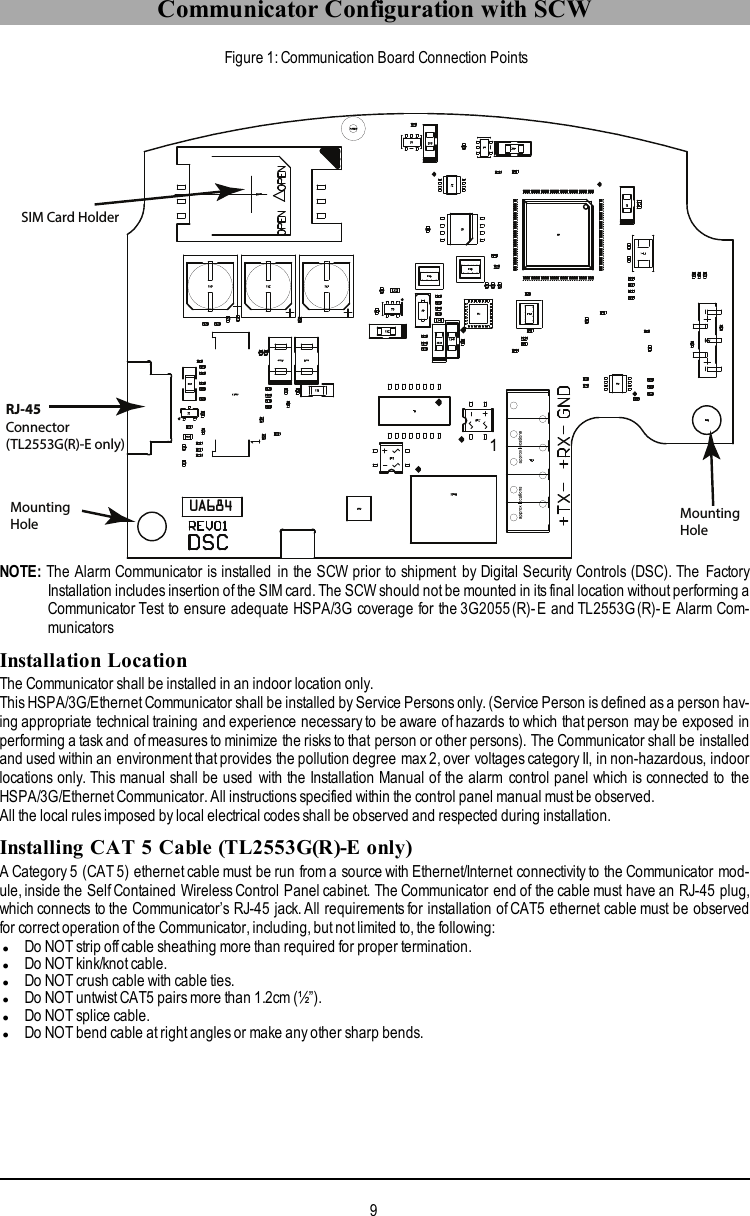
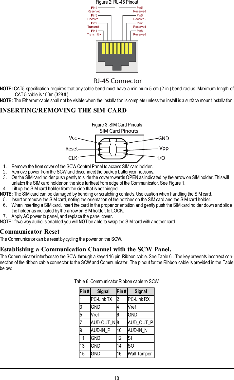
![WARNING: Installer please read carefully 4General Information 5Keypad Data Display 5Entering Data From Keypad 5Entering ASCII Characters 5Mounting Considerations 5Communicator Technical Specifications 6General Information 6Features 6UL/ULC Installation Requirements 6Communicator Frequency Bands for North America 7Ratings 7Hardware Compatibility 7Software Compatability 7Communicator Pre Intsallation Configuration 8Connect24™1 Account and SIM card Activation 8Encryption 8Communicator Configuration with SCW 9Installation Location 9Installing CAT 5 Cable (TL2553G(R)-E only) 9INSERTING/REMOVING THE SIM CARD 10Communicator Reset 10Establishing a Communication Channel with the SCW Panel. 10Initial Programming of Communicator and SCW 11SMS Command and Control Functions 11Label Programming for SMS Message 11Communicator Placement Test 12Ethernet/Cellular Programming Options 12System Options 12Programming Options 14Communications Reporting Codes 16System Test Options [026 - 029] 17Ethernet Receiver 1 Options 18Ethernet Receiver 2 Options 19Ethernet Options 19Cellular Receiver 1 Options 20Cellular Receiver 2 Options 20Cellular Options 21Command and Control Options 22SMS Command and Control Functions 22SMS Command and Control Response 23Receiver Diagnostic Testing 25System Information (Read Only) 25System Reset Defaults 26Communicator Troubleshooting 26Communicator Troubleshooting 28Ethernet Cellular Programming Worksheets 30System Options 30Programming Options 302](https://usermanual.wiki/Tyco-Safety-Canada/15TL2553GRE/User-Guide-2739713-Page-2.png)
![General InformationDomain Name Service (DNS) programming is not permitted in UL/ULC listed systemsKeypad Data DisplaylSection-Toggle Options: The number is displayed when Toggle is ON. The number is not displayed when Toggle is OFF.(e.g., Toggle Options displays:“[--3--6--]”. Options 3and 6are ON, all others are OFF). Pressing keys 1 through 8 willalternately turn the Toggle ON and OFF.lHEX/Decimal Data: Values that are provided with two defaults, separated by a / character, use the format: hexadecimal fol-lowed by decimal equivalent (e.g., Default [0BF5/3061]). Hexadecimal numbers are shown, with all leading zeroes, to thefull field length defined for the number.Entering Data From KeypadTo enter data at the keypad, press the number key, from the table below, to select the character that you want. Pressing thenumber key repeatedly will scroll through the characters available for that key. Press the [*] key and use [<] [>] keys to scroll toone of the following selections: (Press [*] to select the Option.)lASCII Entry. Use this mode to enter ASCII characters from the keypad.lClear to End. This selection will clear the remainder of the display.lClear Display.This selection will completely erase all entries on the display.lChange Case. Toggles between upper/lower case depending on current selection.NOTE: The “0” on the keypad is used to delete characters.Table 1: Data Entry at KeypadKey Value Key Value Key Value1 1-A-B-C 4 4-J-K-L 7 7-S-T-U2 2-D-E-F 5 5-M-N-O 8 8-V-W-X3 3-G-H-I 6 6-P-Q-R 9 9-Y-Z-0Entering ASCII CharactersTo enter American Standard Code for Information Interchange (ASCII) characters at the keypad, perform the following:1. Press [*] and use [<] [>] keys to scroll to “ASCII Entry”.2. Press [*] to select ASCII entry mode.3. Use the [<] [>] keys to scroll to display the ASCII character you want to use and press [*] to accept.4. Press [*] to exit ASCII character entry mode and return to normal entry.NOTE: Authorized access to Connect24 (3G2055(R)-E/TL2553G(R)-E) is required to modify any Ethernet/Cellular Pro-gramming Section. Specific panel sections must be configured for proper operation of the Communicator with thepanel.Mounting ConsiderationsThe Cellular/Ethernet Communicator is a fixed, wall-mounted unit and shall be installed in the location specified in these instruc-tions. The equipment enclosure must be fully assembled and closed, with all the necessary screws/tabs and it mustbe securedto a wall before operation.Internal wiring must be routed in a manner that prevents:lExcessive strain on wire and on terminal connections,lInterference between power limited and non power limited wiring,lLoosening of terminal connections, orlDamage of conductor insulation.WARNING: Never install this equipment during a lightning storm!The Installer must instruct the System user on each of the following items:lThis manual shall be used in conjunction with the Alarm controller manual; All the safety instructions specified within thatmanual shall be observed.lDo not attempt to service this product. Opening or removing covers may expose the user to dangerouslvoltages or other risks.lAny servicing shall be referred to trained service person only.lUse authorized accessories only with this equipment.Cellular Coverage for Alarm Communicator OperationThe HSPA/3G performance of the 3G2055(R)-E and TL2553G(R)-E Alarm Communicators depends greatly on Cellular net-work coverage. The SCW (with internal Alarm Communicator) should not be mounted in the final location without first ensuring5](https://usermanual.wiki/Tyco-Safety-Canada/15TL2553GRE/User-Guide-2739713-Page-5.png)
![Establishing a communication channel between the Communicator and the SCW is critical to ensuring the desired operation ofthe two units. The following steps must be completed during the on-site installation. Program the following to ensure that theCommunicator and the panel will work together as intended.Initial Programming of Communicator and SCW1. Enter [*][8][Installer Code] [Section Number] for panel programming. Record any values that are modified from theirdefault, in the appropriate Programming Worksheets.NOTE: When programming Toggle Options,the toggle is ON when the number is displayed and OFF when the number is notdis played. (e.g.,[1---5---],Toggle Options 1 and 5 are ON, all others are OFF).2. Panel Section [167] Cellular/Ethernet Interface Communications ‘Wait for ACK’: Default value is: 060 seconds.3. When the communicator is installed with the SCW panel, 4 telephone numbers are available to backup one another.You can set up these 4 telephone numbers to perform in one of two ways: Backup dialling or Alternate dialling.a. Backup dialling: each of the 4 telephone numbers will make 5 dialling attempts in turn, before an FTC trouble is dis-played on the keypad.b. Alternate dialling: each telephone number makes 1 dialling attempt before moving on to the next number, cyclingthrough each of the 4 numbers for a total of 5 times each. If all 4 numbers fail the 5 attempts, an FTC trouble is dis-played on the keypad.4. Panel Sections [301], [302], [303], and [305] can be configured as Primary communication paths.a. Panel Sections [302], [303], and [305] may also be configured for backup or redundant communications by usingPanel Section(s) [383] or [351] - [376]. Refer to the SCW panel Installation Manual for more information.b. If a valid telephone number is programmed, communications will use Public Switched Telephone Network (PSTN).Entering a 4 digit hexadecimal value for a telephone number will change the call routing to the Communicator, asdetermined by the number programmed:DCAAF: Internal (All Receivers). Signals will be routed depending on Section [851] [006] programming.DCBBF: Ethernet Receiver 1 (Primary). (Not available for 3G2055(R)-E).DCCCF: Ethernet Receiver 2 (Backup). (Not available for 3G2055(R)-E).DCDDF: Cellular Receiver 1 (Primary).DCEEF: Cellular Receiver 2 (Backup).NOTE: Add a single ‘F’ as a suffix to the 4 digit hex number to populate the unused remainder of the 32 character field.5. Panel Section [350]: If any of the phone numbers have been programmed as DCAA, DCBB, DCCC, DCDD, or DCEE,panel Section [350] must be set to [04] if SIA format or [03] if Contact ID (CID) format is used by control panel.6. Panel Section [382]: Toggle Option [5], ‘GS/IP Module Enabled’, must be set to ON.7. Panel Section [401]: Toggle Option [1] must be set to ON in order to perform panel DLS session through Cellular or Eth-ernet data channel.8. Panel section [310], account code, auto syncs with the communicator account code in section [021]. The panel accountcode ([*][8][installer code] [310]), will overwrite the communicator account code section ([*][8][installer code] [850] [021]) ifprogrammed differently.NOTE: Keep a record of the SIM card telephone number, it is required by users for SMS Command and Control functions.(The number can be recorded in the Programming Worksheets Section of this document, under Option [996]). Due tothe nature of the SIM card activation process with Cellular network carriers, it can take up to 24 hours for SIM card activ-ation to be complete.SMS Command and Control FunctionsSMS Command and Control is available on SCW9055/57 panels. Users can send SMS text messages from their mobile phoneto the GSM phone number assigned to their system. Commands are only accepted from telephone numbers that have beenprogrammed in Sections [311]-[318]. The system will reject messages sent from telephone numbers that are not on the pro-grammed list.When the received SMS text matches a valid Section message, the function is performed on the control panel. Text messagesare not case sensitive and extra spaces are ignored. A User Access Code may be required for some SMS messages.The SMS Message format is in 3 parts:Command, Partition Label (or only the partition number), and Access Code.If an Access Code is included in the message, it is sent to the control panel for validation, along with the requested function.If the panel is configured to require an Access Code and the code is not sent (or invalid) the panel will fail the function (unsuc-cessful).If the panel fails the function, an SMS response message is sent to the user. The SMS response will echo the command sensat,followed by the label “unsuccessful”. (e.g., “night arm partition 2 1234 unsuccessful”).The partition label or partition number may be excluded from the SMS request in a single partition system (e.g., disarm 9123).NOTE: The GSM phone number can be viewed in Section [851] [996], and/or [851] [229] or by entering *6, then scrolling downto “SMS Programming” and scrolling down to “Cellular phone No”.Label Programming for SMS MessageProgrammable Labels can not be modified in Connect24, use DLS IV for label programming only, if labels need to be mod-ified. Before initiating remote programming, record your network’s Public IP Address and port for incoming DLS IV con-nections.11](https://usermanual.wiki/Tyco-Safety-Canada/15TL2553GRE/User-Guide-2739713-Page-11.png)
![1. Run the DLS IV software on your computer. DLS IV will connect to the unit, using the Public IP address, and make an Eth-ernet connection. If the Ethernet connection fails, DLS IV will report an error and prompt you to connect using Cellular.NOTE: If required, download the DLS IV software from DSC: http://www.dsc.com/index.php?n=library#self. If you select Cellularconnection, DLS will request Connect24 to send an outgoing SMS message to the unit.2. Connect24 will confirm that the account has DLS service and will provide the Public IP addressand port number of theDLS server in an SMS message.3. SMS message will establish a connection to your computer’s DLS IV software (to change programming labels only).4. Create an account for the panel/Communicator, select the Communicator type (e.g., SMS - TL2553GR-E) and enter allrelevant information in SMS section.NOTE: The Cellular telephone number will also be required by the user, to send SMS Command and Control messages totheir system.5. Program the account information, then click Global Download and choose SMS as the Connection Type. Click OK.6. The download path configured in Programming Section [005] Toggle Option[4] determines the Cellular or Ethernet pathto be used.Communicator Placement Test(3G2055(R)-E / TL2553G(R)-E only)1. Using the keypad enter the installer mode: [*][8] [installer code] [850].2. View and record the number of bars showing on the SCW LCD.3. Compare with the number of bars indicated in the “CSQ Levels” column shown in Table 7 .4. If 3 or more bars are shown, the location is GOOD and no further action is required.5. If the location is BAD,move the SCW to various suitable locations until 3 or more bars are obtained.Table 7: Communicator CSQ LevelsSignal Strength CSQ Level Signal Level (dBm) Installer ActionNo Signal 0 -108.8 Check if Cellular coverage is active in your area.1 Bar 1 to 4 -108 to -103 Location is BAD. Not suitable for Cellular operation.2 Bars 5 to 6 -102 to -993 Bars 7 to 10 -98 to -90Location is GOOD.4 Bars 11 to 13 -90 to -855 Bars 14 and higher -84 and higherNOTE: The communicator is capable of indicating signal strength even without an active SIM, but signal indication may take upto 1-2 minutes.Ethernet/Cellular Programming OptionsThe Programming Sections described in this document can be viewed at the SCW LCD. To start programming enter: [*][8][installer code] [851][###], Where ### is the 3 digit Section number referenced in this section. The Programming Worksheets atthe end of this document can be used to record the new values when programming changes have been made from the defaultvalues. Programming Sections are accessed through Connect24. Installers may review/record programming Options at thepanel.NOTE: Ethernet/Cellular Programming Sections accessed through the panel are for display purposes only. Configurationchanges must be done using Connect24.System Options[001] Ethernet IP AddressDefault (000.000.000.000)Enter the IP address of the Communicator. Ensure that the IP address is unique to your Communicator on the local network.Format is 4 fields, each field is a 3 digit decimal number. Valid range: 000-255. If an IP address is programmed in this Section,the unit will operate with Static IP (DHCP disabled). Sections [002] and [003] must also be programmed when using Static IPaddresses.NOTE: Default for this Section is Dynamic Host Configuration Protocol (DHCP) enabled. When enabled, the DHCP Server willset values for: IP Address [001], Subnet Mask [002], and Gateway [003]. Programming an IP address in this Section willdisable DHCP (Static IP).[002] Ethernet IP Subnet MaskDefault (255.255.255.000)Enter the Ethernet IP Subnet Mask of the Communicator. Format is 4 fields, each field is 3 digits. Valid range: 000-255.NOTE: If DHCP is enabled, the DHCP Server will assign the subnet mask for this Section and the programmed value will beignored.12](https://usermanual.wiki/Tyco-Safety-Canada/15TL2553GRE/User-Guide-2739713-Page-12.png)
![[003] Ethernet Gateway IP AddressDefault (000.000.000.000)Enter the Ethernet Gateway IP address of the Communicator. The gateway IP address is required when a router is used on thelocal network to reach the destination IP address specified in Section [001]. Format is 4 fields, each field is a 3 digit decimalnumber. Valid range: 000-255.NOTE: If DHCP is enabled, the DHCP Server will assign the Gateway IP addressfor this Section and the programmed valuewill be ignored.[004] Receiver Supervision IntervalDefault (0087/135)When receiver supervision is enabled (ON) in Section [005] Toggle Option [3], the unit sends heartbeats to Ethernet Receiver1 or Cellular Receiver 1 to test the communications path. Use this Section to set the interval time (in seconds) when heartbeatswill be sent to the receivers. Valid range 000A-FFFF seconds. If the programmed value is less than (000A/10) seconds, super-vision is disabled.lReceiver Window: This is the supervision timeout that must be configured at the central station receiver.lRecommended Values: This is the recommended heartbeat interval that should be programmed into the Communicator.lFor ULC installations, the Daily test transmission must be enabled over each available communication channel Sections[125] and [225]. When programming with Connect24, the recommended intervals will be programmed automatically whenthe required window is selected.[005] System Toggle Options[1] Ethernet Receiver 1 SupervisedDefault (OFF)(TL2553G(R)-E only).ON: Ethernet Receiver 1 will be supervised and heartbeatswill be sent to Ethernet Receiver 1 based on the supervision inter-val programmed in Section [004].OFF: Ethernet Receiver 1 will not be supervised. When disabled, heartbeat 1 is sent to the Ethernet receiver once every hour,regardless of supervision type (heartbeat 1 or 2). The heartbeat is resent every 5 seconds until ACK. If no event or heartbeatACK is received after (Receiver Supervision Interval + 75 seconds), Supervisory trouble is indicated.NOTE: Ethernet Receiver 2 can not be supervised.[2] Cellular Receiver 1 SupervisedDefault (OFF)ON: Cellular Receiver 1 will be supervised and heartbeats will be sent to Cellular Receiver 1 based on the supervision intervalprogrammed in Section [004]. If ACK to heartbeat is not received, it is retransmitted every 5 seconds. Failure to ACK 2 con-secutive heartbeats will reset the radio.OFF: Cellular Receiver 1 will not be supervised. When disabled, heartbeat is not sent to the receiver. Supervisory trouble isindicated.NOTE: Cellular Receiver 2 can not be supervised.[3] Supervision TypeDefault (OFF)ON: Heartbeat 1 (Commercial Supervision). This supervision type is suitable for applications where swap detection is requiredon the supervisory packet.OFF: Heartbeat 2 (Residential Supervision). This supervision type is suitable for applications where supervision of the com-munication path to the receiver is required. (no swap detection).NOTE: Commercial supervision is more data intensive than residential supervision and should only be used when required tomeet the approval for the installation.[4] Primary PathDefault (OFF - TL2553G(R)-E) (ON - 3G2055(R)-E)ON: Cellular channel is the primary path. Ethernet channel is the secondary path, if it exists.OFF: Ethernet channel is the primary path in a dual Communicator. Cellular channel is the secondary path.[5] Redundant CommunicationsDefault (OFF) (TL2553G(R)-E only)ON: Events will be communicated to Ethernet Receiver 1 and Cellular Receiver 1 at the same time. Events will be com-municated to Ethernet Receiver 2 and Cellular Receiver 2 at the same time. As long as the event is successfully communicatedto 1 of the 2 paths (Ethernet or Cellular) the Communicator will move on to the next event.NOTE: Do not configure Ethernet Receiver 1 and Cellular Receiver 1 to communicate using a common receiver configuration(i.e., identical Receiver IP address and Receiver Remote Port). OFF: Events will be communicated to the receivers indi-vidually. Toggle should be OFF when guaranteed message delivery to both receivers is required.[6] Remote Firmware UpgradeDefault (ON)ON: The Communicator module firmware can be remotely upgraded using the Ethernet/Cellular paths.OFF: The Communicator module firmware can not be remotely upgraded. Local firmware upgrade is still possible.[7] Alternate Test TransmissionsDefault (OFF).13](https://usermanual.wiki/Tyco-Safety-Canada/15TL2553GRE/User-Guide-2739713-Page-13.png)
![ON: When the periodic test transmission interval occurs, the test transmission will alternate between being sent to the primaryand secondary receivers with each test transmission interval.OFF: When the periodic test transmission interval occurs, the test transmission will be sent to the programmed receivers, basedon the settings of the periodic test transmission reporting codes.[8] Cellular Low Signal Trouble.Default (OFF)This option masks the Low Signal trouble from the Cellular trouble event.ON: A Cellular Trouble event is transmitted to receiver when the radio signal level falls below threshold level (average CSQlevel is 4 or less).OFF: A Cellular Trouble event is not transmitted to receiver when the radio signal level falls below threshold level (averageCSQ level is 4 or less).[006] System Toggle Options 2[1] Ethernet 1 Receiver Enabled.Default (ON) (OFF for 3G2055(R)-E).ON: Ethernet Receiver 1 is enabled.OFF: Ethernet Receiver 1 is disabled.[2] Ethernet 2 Receiver Enabled.Default (ON) (OFF for 3G2055(R)-E).ON: Ethernet Receiver 2 is enabled.OFF: Ethernet Receiver 2 is disabled.[3] Reserved. ( ).[4] Cellular 1 Receiver Enabled.Default (ON).ON: Cellular Receiver 1 is enabled.OFF: Cellular Receiver 1 is disabled.[5] Cellular 2 Receiver Enabled.Default (ON).ON: Cellular Receiver 2 is enabled.OFF: Cellular Receiver 2 is disabled.[6] Reserved ( ).[7] DLS Over Cellular.Default (ON).NOTE: Program this toggle as OFF if you want to completely disable DLS from using the Cellular path.ON: DLS is enabled on the Cellular path.OFF: DLS is disabled on the Cellular path.NOTE: If this Toggle is OFF, DLS sessions will occur on the Ethernet path only, regardless of Primary Path set in Section [005]Toggle Option [4]. If it is ON then the Communicator will connect to the Primary path first for DLS and if the session fails,the Secondary path will be used.[8] Reserved ( ).[007] DNS Server IP 1Default (000.000.000.000)Programming this Section is not permitted on a UL/ULC listed system.Enter the IP address for DNS Server 1. Format is 4 fields, each field is a 3 digit decimal. Valid range: 000-255.NOTE: If no value is programmed and DHCP is used, the DHCP Server will configure the address. If an address is pro-grammed and DHCP is used, the address that you program will be used instead of the DHCP address.[008] DNS Server IP 2Programming this Section is not permitted on a UL/ULC listed system.Default (000.000.000.000)Enter the IP address for DNS Server 2. Format is 4 fields, each field is a 3 digit decimal. Valid range: 000-255.NOTE: Ifno value is programmed and DHCP is used, the DHCP Server will assign this value. If an address is programmed andDHCP is used, the address that you program will be used instead of the DHCP address.Programming Options[010] System Toggle OptionDefault (Disable)[1] This bit is used to enable/disable two way audio over 3G.[011] Installer CodeDefault (CAFE)Program your installer code for this Communicator module. The installer code will be required when programming the Com-municator module. Valid range: 0000 - FFFF.14](https://usermanual.wiki/Tyco-Safety-Canada/15TL2553GRE/User-Guide-2739713-Page-14.png)
![[012] DLS Incoming PortDefault (0BF6/3062)The DLS Incoming Local Port (listening port) is the port DLS IV will use when connecting to the Communicator. If a router orgateway is used, it must be programmed with a Transmission Control Protocol (TCP) port forward for this port to the Com-municator module IP address. Valid range: 0000 - FFFF.[013] DLS Outgoing PortDefault (0BFA/3066)The DLS Outgoing Port is used for outgoing session to DLS IV after an SMS request has been sent to the Communicator. Usethis Section to set the value of the local outgoing port.The value mustbe changed if the Communicator is located behind a fire-wall and must be assigned a particular port number, as determined by your network administrator. In most cases, changing thedefault value or configuring your firewall with this port is not required.Valid range: 0000-FFFF.NOTE: If Section [006] Toggle Option [7] is ON, DLS will use the Primary path for session. If Section [006] Toggle Option [7] isOFF DLS will use the Ethernet path, if available.[020] Time ZoneDefault (00)Use Column 2 (Offset Hours) to find your local Time Zone. Record the two digit HEX value from Column 1 (HEX Value) on thesame row. Program this HEX value for your Time Zone. Valid range is 00 - FF.Table 8: World Wide Time ZonesHEXValueOffsetHoursStandardAbbreviation Location01 -12 BIT Baker Island Time05 -11 SST Somoa Standard Time09 -10 HAST Hawaii-Aleutian Standard Time0B -9.5 MIT Marquesas Island Time0D -9 AKST Alaska Standard Time11 -8 PST Pacific Standard Time15 -7 MST Mountain Standard Time19 -6 CST Central Standard Time1D -5 EST Eastern Standard Time1F -4.5 VST Venezuela Standard Time21 -4 AST Atlantic Standard Time23 -3.5 NST Newfoundland Standard Time25 -3 ART Argentina Time29 -2 BEST Brazil Eastern Standard Time2D -1 CVT Cape Verde Time31 0 GMT Greenwich Mean Time (UTC)35 1 CET Central European Time39 2 SAST South Africa Standard Time3D 3 AST Arabic Standard Time3F 3.5 IRST Iran Standard Time41 4 GST Gulf Standard Time43 4.5 AFT Afghanistan Time45 5 PKT Pakistan Time47 5.5 IST Indian Standard Time48 5.75 NPT Nepal Time49 6 VOST Vostok Time4B 6.5 MMT Myanmar Time15](https://usermanual.wiki/Tyco-Safety-Canada/15TL2553GRE/User-Guide-2739713-Page-15.png)
![HEXValueOffsetHoursStandardAbbreviation Location4D 7 BDT Bangladesh Standard Time51 8 CST China Standard Time52 8.25 APO Apo Island Time54 8.75 ACWST Australian Central Western Standard Time55 9 KST Korea Standard Time57 9.5 ACST Australian Central Standard Time59 10 AEST Australian Eastern Standard Time5B 10.5 LHST Lord Howe Standard Time5D 11 VUT Vanuatu Time5F 11.5 NFT Norfolk Island Time61 12 NZST New Zealand Standard Time64 12.75 CHAST Chatham Island Standard Time65 13 TOT Tonga Time69 14 LINT Line Island Time70-FF N/A N/A N/A[021] Account CodeDefault (FFFFFF)The account code is included when transmitting any events generated by the Communicator. (e.g., Panel Absent Trouble). It isrecommended that the account code be the same as the control panel account number. Valid range: 000001-FFFFFE. If 4 digitaccount codes are needed the 2 lowest digits shall be programmed as FF.(e.g., Account 1234 is programmed as:1234FF).NOTE: Programming this Section with all 0 or F will cause a Module Configuration Trouble.[022] Communications FormatDefault (04)Program 03 for Contact ID (CID). Program 04 for SIA. The module can be configured to send Events in SIA or CID format. TheSIA communication format follows the level 2 specifications of the SIA Digital Communication Standard - October 1997. Thisformat will send the account code along with its data transmission. The transmission will look similar to the following at thereceiver. Example: Nri0 ET001Where: N= New Event; ri0 = Partition/Area identifier; ET = Panel Absent Trouble; 001 = Zone 001.Communications Reporting CodesTable 9: Communications Reporting CodesEvent SIAIdentifierSIAReporting CodeCIDQualifierCIDEvent CodeCIDReporting CodeCIDUser/ Zone[023] Panel Absent Trouble ET 001 1 3 55 001[024] Panel Absent Trouble Restore ER 001 3 3 55 001[025] Radio Activation Restore RS 001 3 5 52 001[026] Ethernet 1 Test Transmission RP 001 1 6 A3 951[027] Ethernet 2 Test Transmission RP 002 1 6 A3 952[028] Cellular 1 Test Transmission RP 003 1 6 A3 955[029] Cellular 2 Test Transmission RP 004 1 6 A3 956[030] FTC Restore YK 001 3 3 54 001[023] Panel Absent TroubleDefault (FF)Program 00 to disable this event or FF to enable. This event will occur when communications with the panel have been lost formore than 60 seconds.[024] Panel Absent Trouble RestoreDefault (FF)16](https://usermanual.wiki/Tyco-Safety-Canada/15TL2553GRE/User-Guide-2739713-Page-16.png)
![Program 00 to disable this event or FF to enable. This event will occur when communications with the control panel haveresumed.[025] Radio Activation RestoreDefault (FF)Program 00 to disable this event or FF to enable. This event will occur after any successful Connect24 programming session.System Test Options [026 - 029]Test Transmissions to Primary Receiver, with Backup to Secondary Receiver:Set Ethernet Section [026] to (FF); [027] to (00). Set Cellular Section [028] to (FF); [029] to (00).lIf the test transmission fails to the primary receiver it will backup to the secondary receiver.lIf the test transmission fails to the secondary receiver an FTC trouble will be generated.Test Transmission Unique to Primary and Secondary Receivers:Set Ethernet Section [026] to (FF); [027] to (FF). Set Cellular Section [028] to (FF); [029] to (FF).lThe module will send periodic test transmissions to each receiver independently, with no backups.lIf the test transmission fails to any of the programmed receivers, an FTC trouble will be generated.Alternate Test Transmission:Alternate Test Transmission can be enabled or disabled in Section [005] Toggle Option [7].[026] Ethernet 1 TransmissionDefault (FF)Program 00 to disable this event transmission or FF to enable. See System Test Options (above) for details on settings.[027] Ethernet 2 TransmissionDefault (00)Program 00 to disable this event transmission or FF to enable. See System Test Options (above) for details on settings.[028] Cellular 1 TransmissionDefault (FF)Program 00 to disable this event transmission or FF to enable. See System Test Options (above) for details on settings.[029] Cellular 2 TransmissionDefault (00)Program 00 to disable this event transmission or FF to enable. See System Test Options (above) for details on settings.NOTE: The time interval (in minutes) between periodic tests is programmed in Section [125] (Ethernet) and Section [225] (Cel-lular).[030] FTC RestoreDefault (FF)Program 00 to disable this event transmission or FF to enable. This event will occur when an FTC Trouble on the systemrestores.[031] Priority Tamper AlarmProgram 00 to disable this event or FF to enable. This event will occur when panel tampered during the entry delay.[032] Priority Tamper RestoreProgram 00 to disable this event or FF to enable.This event will occur when panel tamper restored.Table 10: Priority Temper RestoreEvent SIAIdentifierSIA ReportingCodeContact IDQualifierContact IDEvent CodeContact IDReporting CodeContact IDUser/ZonePriority Tamper BA 000 1 1 37 000Priority Tamper Restore BR 000 3 1 37 000[033] Communicator Firmware Update BeginDefault (FF);Program 00 to disable this event transmission or FF to enable. This event will occur when the communicator firmware updatebegins.[034] Communicator Firmware Update SuccessfulDefault (FF);Program 00 to disable this event transmission or FF to enable. This event will occur when the communicator firmware updatesuccessfully completed.[035] Panel Firmware Update BeginDefault (FF);17](https://usermanual.wiki/Tyco-Safety-Canada/15TL2553GRE/User-Guide-2739713-Page-17.png)
![Program 00 to disable this event transmission or FF to enable. This event will occur when the panel firmware update begins.[036] Panel Firmware Update SuccessfulDefault (FF);Program 00 to disable this event transmission or FF to enable. This event will occur when the panel firmware is updated suc-cessfully.[037] Panel Firmware Update FailDefault (FF);Program 00 to disable this event transmission or FF to enable. This event will occur when the panel firmware updated hasfailed.Table 11: Panel Tamper Alarm RestoreEvent SIAIdentifierSIAReportingCodeContact IDQualifierContact IDEvent CodeContact IDReportingCodeContact IDUser/Zone[033]Comm. FW Update Begin LB 00 1 9 03 002[034]Comm. FW Update Successful LS 00 3 9 03 002[035]Panel FW Update Begin LB 00 1 9 03 003[036]Panel FW Update Successful LS 00 3 9 03 003[037]Panel FW Update Fail LU 00 1 9 04 003Ethernet Receiver 1 Options[101] Ethernet Receiver 1 Account CodeDefault (0000000000)The account code is used by the central station to distinguish between transmitters. This account code is used when trans-mitting heartbeat signals to the central station receiver. Signals received from the Panel will use the control panel account num-ber. Valid range: 0000000001-FFFFFFFFFE. Programming all 0 or all F will cause a Module Configuration Trouble.NOTE: If Ethernet Receiver 1 and Cellular Receiver 1 are programmed as the same receiver (IP and port number areidentical), Ethernet Receiver 1 account code will be used.[102] Ethernet Receiver 1 DNISDefault (000000)The Dialled Number Information Service (DNIS) is used in addition to the Account Code to identify the Communicator moduleat the central station. Valid range: 000000 - 099999. Value is entered as a leading 0 followed by the 5 digit DNIS. Format is Bin-ary Coded Decimal (BCD).NOTE: Each Ethernet/Cellular receiver must be programmed with a unique DNIS.[103] Ethernet Receiver 1 AddressDefault (127.000.000.001)The default address enables the Communicator to operate in Unattended Mode.Unattended Mode is used when a receiver is not available and the unit is required to perform DLS sessions. Typically usedwhere the customer programs the control panel daily due to access control and still wants to receive alarms without buyingextra hardware (receiver) or software.NOTE: When a valid IP address has been programmed, Ethernet Receiver 1 is enabled and will communicate events over theEthernet channel.Ethernet Receiver 1 and Cellular Receiver 1 may be configured to communicate to the same central station receiver. To con-figure the device to operate using this Common Receiver Mode functionality, program Ethernet Receiver 1 and CellularReceiver 1, IP address and port number with identical values.NOTE: When operating in Common Receiver Mode, Ethernet Receiver 1 account code will be used for Ethernet and Cellular.[104] Ethernet Receiver 1 Remote PortDefault (0BF5/3061)This Section determines the remote port of Ethernet receiver 1. Valid range: 0000 - FFFF.[105] Ethernet Receiver 1 Local PortDefault (0BF4/3060)Use this Section to set the value of the local outgoing port. Set the value of this port when your installation is located behind afirewall and must be assigned a particular port number as determined by your central stationsystem administrator. Valid range: 0000 - FFFF.[106] Ethernet Receiver 1 Domain NameDefault ( )18](https://usermanual.wiki/Tyco-Safety-Canada/15TL2553GRE/User-Guide-2739713-Page-18.png)
![Enter the Domain Name as 32 ASCII characters.Programming this Section is not permitted on a UL/ULC listed system.Ethernet Receiver 2 Options[111] Ethernet Receiver 2 Account CodeDefault (0000000000)The account code is used by the central station to distinguish between transmitters. The account code is used when transmittingheartbeat signals to the central station receiver. Signals received from the control panel will use the control panel account num-ber. Valid range: 0000000001- FFFFFFFFFE. Programming all 0 or all F will cause a Module Configuration Trouble (yellowLED=12 flashes).NOTE: Ifboth Ethernet Receiver 2 and Cellular Receiver 2 are the same receiver (IP and port number are identical), EthernetReceiver 2 account will be used for Ethernet and Cellular.[112] Ethernet Receiver 2 DNISDefault (000000)The DNIS is used in addition to the account code to identify the Communicator module at the central station. Valid range:000000 - 099999. Value is entered as leading 0 followed by the 5-digit DNIS. Format is BCD.NOTE: Each Ethernet/Cellular receiver must be programmed with a unique DNIS.[113] Ethernet Receiver 2 AddressDefault (000.000.000.000)Programming the Ethernet receiver 2 IP address with 000.000.000.000 will disable Ethernet.Enter the Ethernet receiver 2 IP address. This address will be provided by your central station system administrator. Format is 4fields, each field is a 3-digit decimal. Valid range: 000-255.NOTE: When a valid IP address has been programmed, Ethernet Receiver 2 is enabled and will communicate events over theEthernet channel.Ethernet Receiver 2 and Cellular Receiver 2 may be configured to communicate to the same central station receiver.To configure the device to operate using this common receiver mode functionality, program the Ethernet Receiver 2 and Cel-lular Receiver 2, IP address and port number with the same values. When operating in common receiver mode the EthernetReceiver 2 account code will be used for communications over Ethernet and Cellular.NOTE: Do not program Ethernet Receiver 1 and Ethernet Receiver 2 to communicate to same receiver.[114] Ethernet Receiver 2 Remote PortDefault (0BF5/3061)This Section is used to program the port number used by Ethernet Receiver 2. Set the value of this port when your installationis located behind a firewall, and mustbe assigned a particular port number as determined by your central station system admin-istrator. Valid range: 0000 - FFFF.NOTE: Do not program Ethernet Receiver 1 and Ethernet Receiver 2 Port with the same value.[115] Ethernet Receiver 2 Local PortDefault (0BF9/3065)Use this Section to program the value of the local outgoing port. You can set the value of this port when your installation is loc-ated behind a firewall and must be assigned a particular port number as determined by your network administrator. Validrange: 0000 - FFFF.NOTE: Do not program Ethernet Receiver 1 and Ethernet Receiver 2 Port with the same value.[116] Ethernet Receiver 2 Domain NameDefault ( )Programming this Section is not permitted on a UL/ULC listed system.Enter the Domain Name as 32 Character ASCII.Ethernet Options[124] Ethernet Test Transmission TimeDefault (9999)Enter a 4 digit number (0000-2359) using the 24-hour clock format (HHMM) to set the testtransmission time of day.Valid range: 00 - 23 hours (HH) and 00 - 59 minutes (MM). Programming a value of 9999 will disable the test transmissiontime.NOTE: The internal date and time will automatically be programmed when the unit communicates with the primary receiver.[125] Ethernet Test Transmission CycleDefault (000000)This value represents the interval between test transmissions, in minutes. Valid range: 000000 - 999999 minutes. Once the unithas sent the initial periodic test transmission, all future test transmissions will be offset by the programmed number of minutes.See Sections [026] - [029].19](https://usermanual.wiki/Tyco-Safety-Canada/15TL2553GRE/User-Guide-2739713-Page-19.png)
![Table 12: Ethernet Test Transmission IntervalTest Transmission Interval Daily Weekly MonthlyProgrammed Minutes 001440 010080 043200NOTE: Minimum value is 000005 minutes. Programming an interval that is less than 5 minutes will disable test transmission.Cellular Receiver 1 Options[201] Cellular Receiver 1 Account CodeDefault (0000000000)The account code is used by the central station to distinguish between transmitters. This account code is used when trans-mitting heartbeat signals to the central station receiver. Signals received from the control panel will use the control panelaccount number. Valid range: 0000000001 - FFFFFFFFFE. Programming all 0 or all F will cause a Module ConfigurationTrouble (yellow LED = 12 flashes).[202] Cellular Receiver 1 DNISDefault (000000)The DNIS is used in addition to the account code to identify the Communicator module at the central station. Valid range:000000 - 099999. Values are entered as leading 0 followed by the five digit DNIS. Format is BCD.NOTE: Each Ethernet/Cellular receiver must be programmed with a unique DNIS.[203] Cellular Receiver 1 AddressDefault (000.000.000.000)Enter the Cellular Receiver 1 IP address. This information will be provided by your central station system administrator. Each 3-digit segment of the address must be within a valid range of 000-255.NOTE: When a valid IP address has been entered, the Cellular is enabled and will communicate eventsover the Cellular chan-nel.[204] Cellular Receiver 1 PortDefault (0BF5/3061)This Section determines the port used by Cellular Receiver 1. Change the default value of this port when your installation is loc-ated behind a firewall, and must be assigned a particular port number as determined by your central station system admin-istrator. Valid range: 0000 - FFFF.NOTE: Programming this Section with 0000 will disable the receiver.[205] Cellular Receiver 1 APNDefault ( )The Access Point Name (APN) determines the Cellular network that the Communicator will connectto. This information is avail-able from your network carrier. Program this Section as 32 ASCII characters.NOTE: When a SIM card with a custom APN is used, the unit will not have access to the Internet. DLS and remote flash can stillbe done if Section [221] is programmed with a valid Public APN.[206] Cellular Receiver 1 Domain NameDefault ( )Programming this Section is not permitted on a UL/ULC listed system.Enter the Domain Name as 32 ASCII characters.This information will be provided by your central station system administrator.Cellular Receiver 2 Options[211] Cellular Receiver 2 Account CodeDefault (0000000000)The account code is used by the central station to distinguish between different transmitters. This account code is used whentransmitting signals to the central station receiver. Signals received on the panel will use the panel account number. Validrange: 0000000001 - FFFFFFFFFE.NOTE: Programming this Section as all 0 or F will cause a Module Configuration Trouble (yellow LED = 12 flashes).[212] Cellular Receiver 2 DNISDefault (000000)The DNIS is used in addition to the Account Code to identify the Communicator module at the central station. Valid range:000000 - 099999. Values are entered as a 0 followed by the 5 digit DNIS value. Format is BCD.NOTE: Each Ethernet/Cellular receiver must be programmed with a unique DNIS.[213] Cellular Receiver 2 AddressDefault (000.000.000.000)Enter the Cellular Receiver 2 IP address. This IP address will be provided by your central station. Format is 4 fields, each field is3-digit decimal. Valid range: 000 - 255.20](https://usermanual.wiki/Tyco-Safety-Canada/15TL2553GRE/User-Guide-2739713-Page-20.png)
![NOTE: When a valid address has been entered, Cellular Receiver 2 is enabled and will communicate events over the Cellularpath.[214] Cellular Receiver 2 PortDefault (0BF5/3061)This Section defines the port of Cellular Receiver 2. Change the value of this port when your installation is located behind a fire-wall and must be assigned a particular port number, as determined by your central station system administrator. Valid range:0000 - FFFF.NOTE: Do not program Cellular Receiver 1 and Cellular Receiver 2 to communicate to the same receiver.[215] Cellular Receiver 2 APNDefault ( )The APN determines the Cellular network that the Communicator will connect to. This information is available from your net-work carrier. Program this Section with up to 32 ASCII characters.NOTE: When a SIM card with a custom APN is used, the unit will not have access to the internet. DLS and remote flash can stillbe done if Section [221] is programmed with a valid Public APN.[216] Cellular Receiver 2 Domain NameDefault ( )Programming this Section is not permitted on a UL/ULC listed system.Enter the Cellular Receiver 2 Domain Name with up to 32 ASCII characters.Cellular Options[221] Cellular Public Access Point NameDefault ( )When the Communicator is operating on a private APN, use this Section to select a public APN for DLS and Remote FirmwareUpdate. This information is available from your network carrier. The APN identifies the public Cellular network that the Com-municator will connect to.[222] Cellular Login User NameDefault ( )Some network carriers require you to provide login credentials when connecting to an APN. Program your login User Name inthis Section. Format is up to 32 ASCII characters.NOTE: This Section is not accessible via SCW keypad programming.[223] Cellular Login PasswordDefault ( )Some network carriers require you to provide login credentials when connecting to an APN. Program your login Password inthis Section.Format is up to 32 ASCII characters.[224] Cellular Test Transmission Time of DayDefault (9999)Enter a 4 digit value using the 24-hour clock format (HHMM) to set the test transmission time of day. Valid range: 00-23 for thehours (HH) and 00-59 for the minutes (MM).NOTE: To disable the test transmission time of day enter 9999 or FFFF in this Section.The internal date and time will be automatically programmed by the primary receiver only.[225] Cellular Test Transmission CycleDefault (000000)This value represents the interval in between test transmissions in minutes. Valid range: 000000 - 999999 minutes. Once theunit has sent the initial periodic test transmission, all future test transmissions will be offset by the programmed number ofminutes. See Sections [026] - [029].Table 13: Cellular Test Transmission IntervalTest Transmission Interval Daily Weekly MonthlyProgrammed Minutes 001440 010080 043200NOTE: Minimum value is 000005 minutes. Programming an interval that is less than 5 minutes will disable test transmission.[226] Cellular Trouble DelayDefault (00)This option is used to program the delay, in minutes, for reporting a Cellular Trouble Delay. Valid entries are 00 - FF. (e.g., for a10 minute Cellular Trouble Delay enter: 0A). There is no reporting delay if value is programmed as 00.21](https://usermanual.wiki/Tyco-Safety-Canada/15TL2553GRE/User-Guide-2739713-Page-21.png)
![[227] Voice Call TimeoutDefault (00);This option sets the Voice Call Timeout, in minutes. Programming a value of 00 will disable timeout. Valid range is 00 to FF.[228] Voice Call Back TimeDefault (0A);This option sets the Voice call back time, in minutes. When the Communicator requests Call Back from the receiver, it willanswer incoming calls during the programmed timeout period. If an incoming call is received after the timeout from requestingcall back, the Communicator will answer the call and immediately hang up. Programming a value of 00 will disable timeout(accept all incoming calls). Default value is 0A/10 seconds.Valid range is 00 to FF.[229] Voice Call Back NumberDefault (SIM Telephone Number);This option sets the Voice Call Back Telephone Number for the receiver. This number is used for Two Way calling. Current SIMtelephone number can be viewed in Section [996]. Valid entry is 32 character ASCII.Command and Control Options[301] Command and Control Toggle Options[1] SMS Notification Default (ON).[2] Reserved Default ( ).[3] SMS Command and Control Default (ON).[4] Reserved Default ( ).[5] SMS Character Format Default.ON: SMS Unicode, maximum message length is 70 characters.OFF: 7 bit SMS, maximum message length is 160 characters.[6] Long SMS Message Handling Default (OFF).ON: If longer than maximum message length, it is split and sent as multiple SMS messages.OFF: If longer than maximum message length, a single, truncated SMS message is sent.[7-8] Reserved Default ( ).[311] - [318] SMS Phone Number 1 - 8Default ( );These Sections may be programmed through DLS IV or the keypad. Up to 8 SMS telephone numbers (4 - 32 digits) can be pro-grammed in Section [31x]Where x is an SMS telephone number from 1 to 8. Leaving programming blank for a telephone num-ber will disable that number. The User can program their own mobile telephone numbers at the keypad using [*] [6] <> “SMSProgramming”. The SMS Command and Control feature utilizes the SMS messaging service provided by the Cellular networkand is subject to the limitations of SMS messaging. These limitations include delayed messages and lack of guaranteed deliv-ery.NOTE: SMS Command and Control (Sections [601] - [618] will only process messages from the mobile telephone numbers pro-grammed in this Section if SMS Command and Control is enabled [301][ 3] ON. SMS responses are listed in Sections[621] - [630]. A blank telephone number is disabled.SMS Command and Control FunctionsUsers can send SMS text messages from their mobile phone to the communicator cellular phone number assigned to their sys-tem. Commands are only accepted from telephone numbers that have been programmed in Sections [311]-[318]. The systemwill reject messages sent from telephone numbers that are not on the programmed list.When the received SMS text matches a valid Section message, the function is performed on the control panel. Text messagesare not case sensitive and extra spaces are ignored. A User Access Code may be required for some SMS messages.The User can send just the partition number or the complete label.(e.g., “Away arm Partition 2 1234” is treated the same as“away arm 2 1234”).The SMS Message format is in 3 parts:Command, Partition Label (or only the partition number), and Access Code.lIf an Access Code is included in the message, it is sent to the control panel for validation, along with the requested function.lIf the panel is configured to require an Access Code and the code is not sent (or invalid) the panel will fail the function(unsuccessful).lIf the panel fails the function, an SMS response message is sent to the user. The SMS response will echo the commandsent, followed by the label “unsuccessful”. (e.g., “night arm partition 2 1234 unsuccessful”).lThe partition label or partition number may be excluded from the SMS request in a single partition system (e.g., disarm9123).NOTE: The communicator cellular phone number can be viewed in Section [851], [996] and/or [851], [229] or by user entering[*][6], then scrolling down to ‘SMS Programming” and scrolling down to “Cellular phone No.” [<] [>] “Cellular PhoneNo.” at the keypad. An Access Code is required for all SMS commands, except Help.[601] Stay ArmDefault (Stay Arm);22](https://usermanual.wiki/Tyco-Safety-Canada/15TL2553GRE/User-Guide-2739713-Page-22.png)
![Send this command to the system to stay arm. It may be followed by a Partition Label or partition number and Access Code.[602] Away ArmDefault (Away Arm);Send this command to the system to away arm. Itmay be followed by a Partition Label or partition number and Access Code.[603] Night ArmDefault (Night Arm);Send this command to the system to night arm.It may be followed by a Partition Label or partition number and Access Code.[604] DisarmDefault (Disarm);Send this command to the system to disarm. It may be followed by a Partition Label or partition number and Access Code.[605] - [608] Activate Command Output 1 - 4Default (Activate Command Output n);Where n is a number from 1 - 4. Send this command to the system to activate a command output.It may be followed by a Par-tition Label or partition number and Access Code.[609] - [612] Deactivate Command Output 1 - 4Default (Deactivate Command Output n);Where n is a number from 1 - 4. Send this command to the system to deactivate a command output.This command may be fol-lowed by a Partition Label or partition number and optional Access Code.[613] BypassDefault (Bypass);Send this command to the system to bypass a Zone. This command should be followed by a Zone label or Zone number andAccess Code.[614] UnbypassDefault (Unbypass);Send this command to the system to unbypass a Zone. This command should be followed by the Zone label or Zone numberand Access Code.[615] Status RequestDefault (Status Request);Send this command to request the status of the system. It may be followed by a partition label or partition number and AccessCode. If partition label is omitted, status of all enabled partitions will be sent. If there is a trouble on the system, the system labelis sent,followed by the trouble label, then the partition status.NOTE: Status Request response may require more than one SMS message, depending on status of the system. There is a 10-second delay between transmission of SMS messages.[616] Alarm Memory RequestDefault (Alarm Memory Request);Send this command to the system to request the alarm memory from the system. This command may be followed by a PartitionLabel or partition number, and Access Code. If partition label is omitted, alarm memory of all partitions will be sent. Alarmmemory responses will include Partition label and Zone label. Up to 8 partitions may be contained in 1 message.NOTE: Alarm Memory Request response may require more than one SMS message, depending on alarm memory of the unit.There is a 10-second delay between transmission of SMS messages.[617] HelpDefault (Help);When help is sent, the SMS response is a listing of all interactive commands that can be sent to the module. Access Code is notrequired.[619] Keypad MessageDefault (Keypad Message);The response format is: [Account Label] [Date and Time] [SMS Function] [Response] [Message Text]. Fields are space delim-ited.When Keypad Message is sent, the SMS response is the message displayed on the keypad. If the message is too long todisplay on the keypad, only the portion displayed is sent in the response.SMS Command and Control ResponseNOTE: SMS Command and Control Response messages are up to 32 ASCII characters (Maximum 160 characters per SMSmessage). The message language is specified in Section [009].SMS responses are sent to the phone that initiated thecommand.[621] Function SuccessfulDefault (Successful);23](https://usermanual.wiki/Tyco-Safety-Canada/15TL2553GRE/User-Guide-2739713-Page-23.png)
![When an SMS Command and Control function is successfully performed by the panel, the successful label is included in theresponse sent to the user, following the command requested. (e.g., if “stay armed” command is completed by the panel, SMSresponse is: “stay armed successful”).[622] Function UnsuccessfulDefault (Unsuccessful);When an SMS Command and Control function is not successfully performed by the panel, the command sent to the unit will beincluded in the response sent to the user, followed by this label. (e.g., if “stay armed” command is not completed, SMSresponse is: “stay armed unsuccessful”).[623] Invalid CommandDefault (Invalid Command);This label will be included in the response message if the command was not accepted as a valid SMS command.[624] System Stay ArmedDefault (Stay Armed);This label will be included in the response to a status request command if a partition is stay armed.[625] System Away ArmedDefault (Away Armed);This label will be included in the response to a status request command if a partition is away armed.[626] System Night ArmedDefault (Night Armed);This label will be included in the response to a status request command if a partition is night armed.[627] System Disarmed ReadyDefault (Disarmed Ready);This label will be included in the response to a status request command if a partition is disarmed and is ready to arm.[628] System Disarmed Not ReadyDefault (Disarmed Not Ready);This label will be included in the response to a status request command if a partition is disarmed and is not ready to arm.[629] System is in AlarmDefault (is in Alarm);This label will be included in the response to a status request command if a partition is in alarm.[630] Trouble LabelDefault (Service is Required);This label will be included in the response to the Alarm Memory command if there are no alarms in memory.[631] No Alarms in MemoryDefault (No Alarm Memory);This label will be included in the response to an Alarm Memory Request if there are no alarmson the system.[634] Error CodeDefault (Error Code);When an SMS initiated function fails, the module will send an error code to the telephone number that was source of theSMS request. Message format is: [Account Label] [Date and Time] [Error Code] [Error Type]. Fields are “space” delimited.Table 14: Error Code FormatClass Definition Error Definition01 DLS01 Bad SMS format02 Session failed due to local network issues03 Unable to connect to remote server04 Bad DLS access code05 DLS lockout active24](https://usermanual.wiki/Tyco-Safety-Canada/15TL2553GRE/User-Guide-2739713-Page-24.png)
![Class Definition Error Definition02 TFTP01 Bad SMS format02 Session failed due to local network issues03 Unable to connect to remote server04 File not found on TFTP server05 File not found on TFTP server06 Update was unsuccessful07 Update was successfulReceiver Diagnostic Testing[901] Diagnostic Test Transmission[1] Ethernet 1 (OFF).[2] Ethernet 2 (OFF).[3] Cellular 1 (OFF).[4] Cellular 2 (OFF).[5],[6],[7],[8] Reserved (OFF).This Section may be used by the installer to force the Communicator to send an immediate test transmission to specific receiv-ers, to verify that the communications paths are available. Diagnostic Test Transmission failure will indicate as FTC trouble (Yel-low LED = 9 flashes). Ifan FTC error occurs when testing all receivers, select only one receiver and repeat testto isolate thereceiver that is not communicating.System Information (Read Only)NOTE: Sections [987] - [998] are provided for information (Read Only). Values in these Sections can not be modified by theInstaller.[987] Language VersionThis Section will display the current Language version of the Communicator.[988] DNS 1 IP AddressThis Section will display the IP address of DNS Server 1. This is useful when the unit is configured for DHCP and you need tosee the IP address was assigned to the device by the DHCP Server. This value is programmed in Section [007] or assigned byDHCP.[989] DNS 2 IP AddressThis Section will display the IP address of DNS Server 2. This is useful when the unit is configured for DHCP and you need tosee the IP address that was assigned to the device by the DHCP Server. This value is programmed in Section [008] orassigned by DHCP.[990] Boot Loader VersionThis Section will display the current Boot Loader version of the Communicator.[991] Firmware VersionThis Section will display the current firmware version of the device. Update worksheetswith new version after a flash update iscompleted.[992] Ethernet IP AddressThis Section will display the IP address of the Ethernet connection. This value is programmed in Section [001] or assigned byDHCP.[993] Ethernet Gateway AddressThis Section will display the IP address of the Ethernet Gateway. This value is programmed in Section [003] or assigned byDHCP.[994] Cellular IP AddressThis Section will display the current dynamic IP address assigned by DHCP to the Cellular connection.NOTE: Cellular uses DHCP (Dynamic IP) only. The Cellular IP address is always provided by the Cellular network (i.e., not pro-grammable).[995] SIM NumberThis Section will display the Subscriber Identity Module (SIM) number of the SIM card installed in the Communicator. Format is:Major Industry Identifier (2 digits) Mobile Country Code (2 or 3 digits); Mobile Network Code (2 - 3 digits); Unique Number (10 -12 digits); and Checksum (1 digit). Valid SIM numbers range is: 18 - 21 numbers. This number is printed on SIM and the out-side of the Communicator carton.NOTE: The Checksum digit is omitted on 19-digit SIM Card numbers.25](https://usermanual.wiki/Tyco-Safety-Canada/15TL2553GRE/User-Guide-2739713-Page-25.png)
![[996] Cellular Telephone NumberNOTE: This Section will display the Cellular telephone number of the SIM. This telephone number is required by the Installerfor DLS and remote firmware (flash) update. User can access this telephone number by entering [*] [6] < > “CellularPhone No.” to display the phone number.[997] IMEI NumberThis Section will display the unique 15-digit International Mobile Equipment Identity (IMEI) of the radio. Format is: ReportingBody Identifier (2 digits), Allocation Number (4 digits); Final Assembly Code (2 digits); Serial Number (6 digits); and a checkdigit.[998] MAC AddressThis Section will display the unique12-digit, hexadecimal number assigned as the Media Access Control (MAC) address of thedevice.System Reset Defaults[999] Software DefaultDefault (99);The Software default allows the installer to refresh the unit after changes and also return the Communicator to the default state.00: Default Module. All programming Sections in module revert to factory settings. This will erase all existing programming ofthe unit.55: Reset. The Communicator is reset.This option is equivalent to power cycling the Communicator.Communicator Troubleshooting[984] Communicator StatusThe communicator status sections are intended to provide the installer with real-time status of the communicator’s functionality,operational readiness, failures, and potential malfunctions that may affect flawless operation of the communicator and itsprimary function of sending signal to the central station in case the monitored event occurs.The communicator status is displayed in the form of a 6-digit CODE (6 hexadecimal numbers) as in the following pattern:00000F. The range of the code is from: 00000F – 2220CF. Not all numbers in this range are assigned a status code (Somenumbers are skipped, i.e. not assigned the code).Each digit represents a status or trouble indicator (or assigned function when no trouble is present) as described below:1. Digit 1 - Signal Indicator 1, displays the presence/strength of signal 1.2. Digit 2 - Signal Indicator 2, displays the presence/strength of signal 2.3. Digit 3 - Network Indicator, displays the presence (operational status) of network.4. Digit 4 & 5 – TROUBLE INDICATOR displays the type of problem/malfunction on communicator or modules associatedwith and connected to communicator.5. Digit 6 – Reserved for future use.For example, status code 11002F – when interpreted means: “Signal Indicator 1 OK, Signal indicator 2 OK, there is no networktrouble, and there is trouble in the communicator, Panel supervision trouble.” For details see the table below:Table 15: Communicator Status and Trouble Coding in Hexadecimal NumbersDigit 1 Digit 2 Digit 3 Digits 4 & 5 Digit 6Signal Indicator 1 Signal Indicator 2 Network Indicator TROUBLE INDICATOR Future Use0 Off 0 Off 0 Off 00 Off (No trouble) F1 On 1 On 1 On 01 Future use F2 Flashing 2 Flashing 2 Flashing 02 Panel supervision trouble F03 Future use F04 Lockout trouble F05 3G/Cellular trouble F06 Ethernet Trouble F07 Receiver Not Available F08 Receiver Supervision trouble F09 FTC Trouble F0A C24 Configuration SMS Failure F0B Future use F0C Module configuration Trouble F26](https://usermanual.wiki/Tyco-Safety-Canada/15TL2553GRE/User-Guide-2739713-Page-26.png)
![The communicator status codes will indicate the signal levels with digit 1 and 2, a network status with digit 3, and the troublestatus with digit 4 and 5 as indicated in table above. For example status code 11000F would display following status:1 – On = Signal indicator 1, is ON1 – On = Signal indicator 2, is ON0 – OFF = Network indicator, network is working00 – TROUBLE INDICATOR = there is no trouble on the communicator.F – Future code not assigned yet. Itis sixth hexadecimal digit.It could be also ‘ - ‘ (dash) instead of letter F (11000-).In this example both signal indicators are on indicating that communicator has excellent signal level; the network indicator isOFF showing that we do not have any network problems and trouble indicators are both OFF indicating that we don’t have anytrouble on the communicator.[985] Radio Initialization StatusThe radio initialization status is intended to provide the installer with real-time status of radio communication. The radio ini-tialization status is displayed in an 8 bit toggle option. Each digit indicates one task in the radio initialization process as follows:1. Radio power up2. Received the SMS from C243. Radio reset4. Radio attached to network5. Receiver 1 Initialized6. Receiver 2 Initialized7. Receiver 3 Initialized8. Receiver 4 InitializeThe following table showseach digit position in the status code, each digit’s value and its assigned meaning in the eight-digitcode:Table 16: Radio Initialization Status - 1-8 bits completionBit 12345678Not Completed - - - - - - - -Completed 1 2 3 4 5 6 7 8For example, the radio initialization status code 12-45--- indicates that Radio has been powered up, it has received SMS signalfrom C24, the radio is attached to the network, and Receiver 1 has been initialized. This code could be followed with...567 ifReceivers 2, 3, and 4 are initialized where applicable.If the radio initialization status code does not indicate any problems,proceed with installation as per this manual. If troubles arereported, reset the initialization process. If this action does not fix the problem,refer to Trouble shooting section in this manual.Table 17: Trouble Code IndicatorsTroubleIndicatorDigitPossible Causes Trouble Possible Solutions00 No Trouble N/A02 Panel Supervision TroubleCheck Section [382]Toggle Option[5] is ON (3G/Ethernet Module Enabled).Ensure the PC- LINK cable between the Panel and Communicator isconnected properly (not reversed) and is securely in place.04 Lockout Trouble The SIM card has incorrect PIN programmed or has a PIN that the moduledoes not recognize. Replace the SIM card.05 3G/Cellular TroubleConfirm that 3G service is available and active in your area.Check all antenna connections.Ensure average radio signal strength is CSQ 6 or higher. (See Table 7).Ensure the SIM card is properly inserted into the SIM card holder.Ensure the SIM card has been activated. (Could take up to 24 hrs after install).If this trouble persists, relocate the Panel (and Communicator) or install anexternal antenna extension kit.06 Ethernet TroubleCheck with your ISP to confirm Internet service is active in your area.Ensure your Ethernet cable is securely inserted into the RJ45 jack of theCommunicator and the Hub/Router/ Switch.Check that the link light on the Hub/Router/ Switch is ON. If link light is OFF, tryrestarting the Hub/Router/ Switch.If DHCP is used, ensure that the unit has an assigned IP address from theserver.27](https://usermanual.wiki/Tyco-Safety-Canada/15TL2553GRE/User-Guide-2739713-Page-27.png)
![TroubleIndicatorDigitPossible Causes Trouble Possible SolutionsIn Section [851] [992] verify a valid IP address is programmed. If not, contactthe Network administrator.If problem persists, replace the Ethernet cable and RJ45 connector.07 Receiver Not AvailableEnsure that the Ethernet path has internet connectivity.If you are using a static IP address make sure the gateway and subnet maskare entered correctly.If the network has a firewall, ensure the network has the programmed outgoingports open (Default UDP Port 3060 and Port 3065).Ensure that all the receivers are programmed for DHCP or have the proper IPaddress and port number.Ensure the 3G Receiver APNs have been programmed with the Access PointName provided by your 3G provider.08 Receiver Supervision TroubleThis trouble is indicated when supervision is enabled and the unit is not able tosuccessfully communicate with the receiver.If this trouble persists, contact your central station.09 FTC TroubleThe unit has exhausted all communications attempts to all programmedreceivers for events generated by the Communicator.Restart the system. If trouble persists, contact your dealer.0A Connect24 Configuration FailureThe SIM is active but there is no programming for the Communicator.Ensure a profile has been programmed in Connect-24 for the SIM.You can confirm your programming by calling the Connect- 24 VRU, or bylogging into the Connect24 VRU web site.0C Module Configuration TroubleThis indication appears when Section [021] System Account Code, Section[101], [111], [201], and [211] Receiver Account Code have not beenprogrammed. Ensure that a valid account code has been entered in theseSections.Communicator TroubleshootingThe status code for the radio signal strength, its typical troubles, possible causes and troubleshooting instructions is displayedin the table below.Table 18: Radio Signal StrengthSignalStrengthCSQLevelSignalIndicator 1SignalIndicator 2Signal Level[dBm]Signal LevelStatus Action RequiredNo Signal 0 0 0 -108.8 badCheck all antenna connections.Confirm 3G service is active in area.Relocate Panel.1 Bar 1 - 4 0 2 -108 ~ -103 weak Relocate Panel if signal strength showsless than 3 bars.2 Bars 5 - 6 0 1 -102 ~ -99 weak3 Bars 7 - 10 2 1 -98 ~ -91 strongLocation is OK. 3G Signal Strength isgreater than CSQ 7.4 Bars 11 - 13 2 1 -90 ~ -85 strong5 Bars 14 + 1 1 -84 andhigher excellentThe table below displays the Network indicator codes and meaning of each code.Table 19: Network indicator - Digit 3Network indicator Value MeansOFF No Network TroubleONEthernet Cable disconnectedEthernet DHCP failedRadio connection has been restRadio IP failed28](https://usermanual.wiki/Tyco-Safety-Canada/15TL2553GRE/User-Guide-2739713-Page-28.png)
![Ethernet Cellular ProgrammingWorksheetsSystem Options[001] Ethernet IP AddressDefault (000.000.000.000)[002] Ethernet IP Subnet MaskDefault (255.255.255.000)[003] Ethernet Gateway IP AddressDefault (000.000.000.000)[004] Receiver Supervision IntervalDefault (0087/135) Valid range: 0000 - FFFF.[005] System Toggle Options[1] Ethernet Receiver 1 Supervised Default (OFF).[2] Cellular Receiver 1 Supervised Default (OFF).[3] Supervision Type Default (OFF).[4] Primary Communications Path.Default [OFF] TL2553G(R)-E; [ON] 3G2055(R)-E.[5] Redundant Communications Default (OFF).[6] Remote Firmware Upgrade Default (ON).[7] Alternate Test Transmission Default (OFF).[8] Cellular Low Signal Trouble Default (OFF).[006] System Toggle Options 2[1] Ethernet Receiver 1 Enabled Default (ON).[2] Ethernet Receiver 2 Enabled Default (ON).[4] Cellular Receiver 1 Enabled Default (ON).[5] Cellular Receiver 2 Enabled Default (ON).[7] DLS Over Cellular Default (ON).[8] Interactive Over Cellular Default (ON).[007] DNS Server IP 1Programming not permitted on UL/ULC listed system.Default (000.000.000.000)[008] DNS Server IP 2Programming not permitted on UL/ULC listed system.Default (000.000.000.000)Programming Options[010] System Toggle Options 3[1] Enable 2-way audio over 3G[011] Installer CodeDefault (CAFE) Valid range: 0000 - FFFF.[012] DLS Incoming PortDefault (0BF6/3062) Valid range: 0000 - FFFF.[013] DLS Outgoing PortDefault (0BFA/3066) Valid range: 0000 - FFFF.[020] Time ZoneDefault (00) Valid range: 00 - 99.[021] Account CodeDefault (FFFFFF) Valid range: 000001 - FFFFFE.[022] Communications FormatDefault (04) Program 03 (CID), 04 (SIA).[023] Panel Absent TroubleDefault (FF); Program 00 disable or FF enable.[024] Panel Absent Trouble RestoreDefault (FF) Program 00 disable or FF enable.[025] Radio Activation RestoreDefault (FF) Program 00 disable or FF enable.System Test Options[026] Ethernet 1 TransmissionDefault (FF) Program 00 disable or FF enable.[027] Ethernet 2 TransmissionDefault (00) Program 00 disable or FF enable.[028] Cellular 1 TransmissionDefault (FF) Program 00 disable or FF enable.[029] Cellular 2 TransmissionDefault (00) Program 00 disable or FF enable.[030] FTC RestoreDefault (FF) Program 00 disable or FF enable.[031] Priority Tamper AlarmDefault (FF) Program 00 disable or FF enable.30](https://usermanual.wiki/Tyco-Safety-Canada/15TL2553GRE/User-Guide-2739713-Page-30.png)
![[032] Priority Tamper RestoreDefault (FF) Program 00 disable or FF enable.[033] Communicator Firmware Update BeginDefault (FF) Program 00 disable or FF enable.[034] Communicator Firmware Update Suc-cessfulDefault (FF) Program 00 disable or FF enable.[035] Panel Firmware Update BeginDefault (FF) Program 00 disable or FF enable.[036] Panel Firmware Update SuccessfulDefault (FF) Program 00 disable or FF enable.[037] Panel Firmware Update FailDefault (FF) Program 00 disable or FF enable.Ethernet Receiver 1 Options[101] Ethernet Receiver 1 Account CodeDefault (0000000000)Valid range: 0000000001 - FFFFFFFFFE.[102] Ethernet Receiver 1 DNISDefault (000000) Valid range: 000000 - FFFFFF.[103] Ethernet Receiver 1 AddressDefault (127.000.000.001)[104] Ethernet Receiver 1 UDP Remote PortDefault (0BF5/3061) Valid range: 0000 - FFFF.[105] Ethernet Receiver 1 UDP Local PortDefault (0BF4/3060)Valid range: 0000 - FFFF.[106] Ethernet Receiver 1 Domain NameDefault ( ) 32 ASCII characters.Programming not permitted on UL/ULC listed system.________________________________Ethernet Receiver 2 Options[111] Ethernet Receiver 2 Account CodeDefault (0000000000)Valid range: 0000000001 - FFFFFFFFFE.[112] Ethernet Receiver 2 DNISDefault (000000) Valid range: 000000 - 0FFFFF.[113] Ethernet Receiver 2 AddressDefault (000.000.000.000)[114] Ethernet Receiver 2 UDP Remote PortDefault (0BF5/3061) Valid range: 0000 - FFFF.[115] Ethernet Receiver 2 UDP Local PortDefault (0BF9/3065) Valid range: 0000 -FFFF.[116] Ethernet Receiver 2 Domain NameDefault ( )Programming not permitted on UL/ULC listed system.____________________________________Ethernet Options[124] Ethernet Test Transmission TimeDefault (9999) Valid: 00-23(HH); 00-59(MM)[125] Ethernet Test Transmission CycleDefault (000000)Valid range:000000 - 999999 minutes.Cellular Receiver 1 Options[201] Cellular Receiver 1 Account CodeDefault (0000000000)Valid range: 0000000001 - FFFFFFFFFE.[202] Cellular Receiver 1 DNISDefault (000000) Valid range: 000000 - 0FFFFF.[203] Cellular Receiver 1 AddressDefault (000.000.000.000). Valid range: 000-255.[204] Cellular Receiver 1 PortDefault (0BF5/3061) Valid range: 0000 - FFFF.[205] Cellular Receiver 1 APN Default ( )32 ASCII characters.____________________________________[206] Cellular Receiver 1 Domain NameDefault ( )32 Character ASCII characters.____________________________________Cellular Receiver 2 Options[211] Cellular Receiver 2 Account CodeDefault (0000000000)Valid range: 0000000001 - FFFFFFFFFE.31](https://usermanual.wiki/Tyco-Safety-Canada/15TL2553GRE/User-Guide-2739713-Page-31.png)
![[212] Cellular Receiver 2 DNISDefault (000000)Valid range: 000000 - 0FFFFF.[213] Cellular Receiver 2 AddressDefault (000.000.000.000)Valid segment range: 000-255[214] Cellular Receiver 2 PortDefault (0BF5/3061) Valid range: 0000 - FFFF.[215] Cellular Receiver 2 APNDefault ( ) 32 ASCII characters.____________________________________[216] Cellular Receiver 2 Domain NameDefault ( ) 32 ASCII characters.Programming not permitted on UL/ULC listed system.____________________________________Cellular Options[221] Cellular Public Access Point NameDefault ( ) 32 ASCII characters____________________________________[222] Cellular Login User NameDefault ( ) 32 ASCII characters.____________________________________[223] Cellular Login PasswordDefault ( ) 32 ASCII characters.____________________________________[224] Cellular Test Transmission Time of DayDefault (9999) Valid range: 00 - 23 hrs. (HH) 00 - 59 min.(MM).[225] Cellular Test Transmission CycleDefault (000000)Valid range:000000 - 999999 minutes.[226] Network Trouble DelayDefault (0F)Valid entries from, 00 to FF.Command and Control Options[301] Command and Control Toggle Options[1] Reserved[2] Reserved[3] SMS Command and Control Default (ON).[4] Reserved[5] SMS Character Format (OFF)[6] Long SMS Message Handling Default (OFF).[7] Reserved[8] Reserved[311]-[318] SMS Phone Number 1-8This section may be programmed through DLS-IV or thekeypad.______________________________________________[321]-[328] SMS Phone Number 1-8 ToggleOptions[1] SMS Notification Alarm/Restore Default (OFF).[2] SMS Notification Tamper/Restore Default (OFF)[3]SMSNotificationOpening/ClosingDefault(OFF).[4] SMS Notification System Maintenance Default(OFF)[5] SMS Notification System Test Default (OFF)[6] SMS Notification Internal Events Default (OFF).[7] SMS Notification Enabled Default (OFF).[8] SMS Command and Control Enabled Default(ON).[601] Stay ArmDefault (Stay Arm)Send this command to the system to stay arm.______________________________________________[602] Away ArmDefault (Away Arm)Send this command to the system to away arm.______________________________________________[603] Night ArmDefault (Night Arm)Send this command to the system to night arm.______________________________________________[604] DisarmDefault (Disarm)Send this command to the system to disarm.______________________________________________[605]-[608] Activate Command Output 1-4Default (Activate Command Output n)Send this command to the system to activate a command out-put.______________________________________________[609]-[612] Deactivate Command Output 1-4Default (Deactivate Command Output n)Send this command to the system to deactivate a commandoutput.______________________________________________[613] BypassDefault (Bypass)Send this command to the system to bypass a zone.______________________________________________[614] UnbypassDefault (Unbypass)Send this command to the system to unbypass a Zone.32](https://usermanual.wiki/Tyco-Safety-Canada/15TL2553GRE/User-Guide-2739713-Page-32.png)
![______________________________________________[615] Status RequestDefault (Status Request)Send this command to request the status of the system.______________________________________________[616] Alarm Memory RequestDefault (Alarm Memory Request)Send this command to request the alarm memory from thesystem.______________________________________________[617] HelpDefault (Help)Access Code is not required.______________________________________________[619] Keypad MessageDefault (Keypad Message)[Account Label] _________________________________[Date and Time] _________________________________[SMS Function] _________________________________[Response] ____________________________________[Message Text]_________________________________[621] Function SuccessfulDefault (Successful)Example: “stay armed successful.”______________________________________________[622] Function FailureDefault (Unsuccessful)Example: “stay armed unsuccessful.”______________________________________________[623] Invalid CommandDefault (Invalid Command)Unprogrammable, enter correct command.______________________________________________[624] System Stay ArmedDefault (Stay Armed)Included in the response message if the command was notaccepted as a valid SMS command.______________________________________________[625] System Away ArmedDefault (Away Armed)Included in the response to a status request command if a par-tition is away armed.______________________________________________[626] System Night ArmedDefault (Night Armed)Included in the response to a status request command if a par-tition is night armed.______________________________________________[627] System Disarmed ReadyDefault (Disarmed Ready)Included in the response to a status request command if a par-tition is disarmed and is ready to arm.______________________________________________[628] System Disarmed, Not ReadyDefault (Disarmed Not Ready)Included in the response to a status request command if a par-tition is disarmed and is not ready to arm.______________________________________________[629] System In AlarmDefault (is in Alarm)This label will be included in the response to an AlarmMemory Request if there are no alarms on the system______________________________________________[630] Trouble LabelDefault (Service is Required)Included in the response to the Alarm Memory command ifthere are no alarms in memory.______________________________________________[631] No Alarms in MemoryDefault (No Alarms in Memory)Included in the response to the Alarm Memory command ifthere are no alarms on the system.______________________________________________[634] Response CodeDefault (Response Code)Included in the response to an Alarm Memory Request ifthere are no alarms on the system______________________________________________Receiver Diagnostic Testing[901] Diagnostic Test Transmission[1] Ethernet 1 Default (OFF).[2] Ethernet 2 Default (OFF).[3] Cellular 1 Default (OFF).[4] Cellular 2 Default (OFF).System Information (Read Only)[988] DNS 1 IP Address[989] DNS 2 IP Address[991] Firmware Version[992] Ethernet IP Address[993] Ethernet Gateway Address[994] Cellular IP Address[995] SIM Number____________________________________[996] Cellular Telephone NumberThis number is required for DLS and Firmware upgrades.____________________________________[997] IMEI Number____________________________________33](https://usermanual.wiki/Tyco-Safety-Canada/15TL2553GRE/User-Guide-2739713-Page-33.png)
![[998] MAC AddressSystem Reset Defaults[999] Software DefaultDefault (99); Valid entries are 00 or 55EULAIMPORTANT - READ CAREFULLY: DSC Software purchased with or withoutProductsand Componentsis copyrighted and ispurchased under the followinglicense terms:ThisEnd- UserLicense Agreement (“EULA”) isa legal agreement between You(the company, individual or entity who acquired the Software and any relatedHardware) and Digital Security Controls, a division of Tyco Safety ProductsCanada Ltd. (“DSC”), the manufacturer of the integrated security systems andthe developer of the software and any related products or components(“HARDWARE”)which You acquired.If the DSC software product (“SOFTWAREPRODUCT” or“SOFTWARE”)is inten-ded to be accompanied by HARDWARE, and is NOT accompanied by newHARDWARE, You may not use, copy orinstall the SOFTWARE PRODUCT. TheSOFTWARE PRODUCT includes computer software, and may include asso-ciated media, printed materials, and “online” orelectronic documentation.Anysoftware provided along with the SOFTWAREPRODUCT that is associatedwith a separate end-user license agreement islicensed to You underthe terms ofthat license agreement.By installing, copying, downloading, storing, accessing or otherwise using theSOFTWAREPRODUCT, You agree unconditionallyto be bound by the terms ofthis EULA, even if this EULA is deemed to be a modification of any previousarrangement or contract. If You do not agree to the terms of thisEULA, DSC isunwilling to license the SOFTWAREPRODUCT to You, and You have no right touse it.SOFTWARE PRODUCT LICENSEThe SOFTWARE PRODUCT is protected by copyright laws and internationalcopyright treaties, as well as other intellectual property laws and treaties. TheSOFTWAREPRODUCT islicensed, not sold.1. GRANT OF LICENSE This EULA grants You the following rights:Software Installation and Use -For each license You acquire, You may haveonlyone copyof the SOFTWAREPRODUCT installed.Storage/Network Use - The SOFTWARE PRODUCT may not be installed,accessed, displayed, run, shared or used concurrentlyon or from different com-puters, including a workstation, terminal or other digital electronic device(“Device”). In other words, if You have several workstations, You will have toacquire a license foreach workstation where the SOFTWAREwillbe used.Backup Copy - You maymake back-up copies of the SOFTWARE PRODUCT,but You may onlyhave one copyper license installed at anygiven time. You mayuse the back-up copysolelyfor archivalpurposes. Except asexpressly provided inthisEULA, You maynot otherwise make copiesof the SOFTWARE PRODUCT,including the printed materialsaccompanying the SOFTWARE.2. DESCRIPTION OFOTHER RIGHTSAND LIMITATIONSLimitations on Reverse Engineering, Decompilation and Disassembly -You may not reverse engineer, decompile, or disassemble the SOFTWAREPRODUCT, except and only to the extent that such activityisexpressly permittedbyapplicable law notwithstanding thislimitation. You may not make any changesormodifications to the Software, without the written permission of an officer ofDSC. You may not remove any proprietarynotices, marksor labels fromthe Soft-ware Product. You shallinstitute reasonable measuresto ensure compliance withthe termsand conditionsof thisEULA.Separation of Components - The SOFTWARE PRODUCT is licensed as asingle product. Its component parts may not be separated for use on more thanone HARDWAREunit.Single INTEGRATED PRODUCT - If You acquired this SOFTWARE withHARDWARE, then the SOFTWAREPRODUCT is licensed with the HARDWAREasa single integrated product. In thiscase, the SOFTWAREPRODUCT may onlybe used with the HARDWAREasset forth in thisEULA.Rental - You may not rent, lease orlend the SOFTWAREPRODUCT. You maynot make it available to othersorpostit on a serveror web site.Software Product Transfer -You maytransfer allof Your rights under this EULAonlyas part of a permanent sale or transfer of the HARDWARE, provided Youretain no copies, You transferallof the SOFTWAREPRODUCT (including all com-ponent parts, the media and printed materials, any upgrades and this EULA),and provided the recipient agrees to the terms of this EULA. If the SOFTWAREPRODUCT is an upgrade, anytransfer must also include all priorversions of theSOFTWAREPRODUCT.Termination - Without prejudice to any other rights, DSC may terminate thisEULA if You fail to comply with the terms and conditions of this EULA. In suchevent, You must destroy allcopies of the SOFTWAREPRODUCT and all of its com-ponentparts.Trademarks - ThisEULA doesnot grant You anyrights in connection with anytrademarks or service marksof DSC oritssuppliers.3. COPYRIGHTAlltitle and intellectualpropertyrightsin and to the SOFTWAREPRODUCT (includ-ing but not limited to any images, photographs, and text incorporated into theSOFTWAREPRODUCT), the accompanying printed materials,and anycopies ofthe SOFTWARE PRODUCT, are owned by DSC or its suppliers. You may notcopythe printed materialsaccompanying the SOFTWAREPRODUCT. Alltitle andintellectualpropertyrights in and to the content which maybe accessed throughuse of the SOFTWARE PRODUCT are the property of the respective contentowner and maybe protected byapplicable copyright orotherintellectualpropertylawsand treaties. This EULAgrants You no rights to use such content. All rightsnot expresslygranted under thisEULAare reserved byDSC and itssuppliers.EXPORT RESTRICTIONS- You agree that You will not export orre-export theSOFTWARE PRODUCT to any country, person, or entity subject to Canadianexport restrictions.CHOICEOFLAW - This Software License Agreement isgoverned by the laws ofthe Province of Ontario, Canada.ARBITRATION - All disputes arising in connection with this Agreement shall bedetermined byfinaland binding arbitration in accordance with the Arbitration Act,and the partiesagree to be bound bythe arbitrator’sdecision. The place of arbit-ration shall be Toronto, Canada, and the language of the arbitration shall beEnglish.LIMITED WARRANTYNO WARRANTY - DSC PROVIDES THE SOFTWARE “AS IS” WITHOUTWARRANTY. DSC DOES NOT WARRANT THAT THE SOFTWARE WILL MEETYOUR REQUIREMENTS OR THAT OPERATION OF THESOFTWARE WILL BEUNINTERRUPTED OR ERROR-FREE.CHANGES IN OPERATING ENVIRONMENT - DSC shallnot be responsible forproblemscaused bychangesin the operating characteristicsof the HARDWARE,orfor problems in the interaction of the SOFTWARE PRODUCT with non- DSC-SOFTWAREorHARDWAREPRODUCTS.LIMITATION OF LIABILITY; WARRANTY REFLECTS ALLOCATION OFRISK - IN ANY EVENT, IF ANY STATUTE IMPLIES WARRANTIES ORCONDITIONS NOT STATED IN THIS LICENSE AGREEMENT, DSC’S ENTIRELIABILITYUNDER ANYPROVISION OF THISLICENSEAGREEMENT SHALL BELIMITED TO THE GREATER OF THE AMOUNT ACTUALLY PAID BY YOU TOLICENSE THE SOFTWARE PRODUCT AND FIVE CANADIAN DOLLARS(CAD$5.00). BECAUSE SOME JURISDICTIONS DO NOT ALLOW THEEXCLUSION OR LIMITATION OF LIABILITY FOR CONSEQUENTIAL ORINCIDENTAL DAMAGES, THE ABOVELIMITATION MAY NOT APPLYTO YOU.DISCLAIMER OF WARRANTIES - THISWARRANTYCONTAINSTHE ENTIREWARRANTYAND SHALL BEIN LIEU OFANYAND ALL OTHER WARRANTIES,WHETHER EXPRESSED OR IMPLIED (INCLUDING ALL IMPLIEDWARRANTIES OF MERCHANTABILITY OR FITNESS FOR A PARTICULARPURPOSE)AND OFALL OTHER OBLIGATIONSOR LIABILITIESON THE PARTOF DSC. DSC MAKES NO OTHER WARRANTIES. DSC NEITHER ASSUMESNOR AUTHORIZES ANY OTHER PERSON PURPORTING TO ACT ON ITSBEHALFTO MOD8IFY OR TO CHANGE THIS WARRANTY, NOR TO ASSUMEFOR IT ANY OTHER WARRANTY OR LIABILITY CONCERNING THISSOFTWAREPRODUCT.EXCLUSIVE REMEDY AND LIMITATION OF WARRANTY - UNDER NOCIRCUMSTANCESSHALL DSC BE LIABLE FOR ANY SPECIAL, INCIDENTAL,CONSEQUENTIAL OR INDIRECT DAMAGES BASED UPON BREACH OFWARRANTY, BREACH OF CONTRACT, NEGLIGENCE, STRICT LIABILITY, ORANY OTHER LEGAL THEORY. SUCH DAMAGES INCLUDE, BUT ARE NOTLIMITED TO, LOSS OF PROFITS, LOSS OF THE SOFTWARE PRODUCT ORANY ASSOCIATED EQUIPMENT, COST OF CAPITAL, COST OF SUBSTITUTEOR REPLACEMENT EQUIPMENT, FACILITIES OR SERVICES, DOWN TIME,PURCHASERS TIME, THE CLAIMS OF THIRD PARTIES, INCLUDINGCUSTOMERS, AND INJURYTO PROPERTY.DSC recommends that the entire system be completelytested on a regular basis.However, despite frequent testing, and due to, but not limited to, criminal tam-pering or electricaldisruption, it ispossible for thisSOFTWAREPRODUCT to fail toperformasexpected.DigitalSecurityControlswarrantsthe originalpurchaserthat fora period of twelvemonthsfromthe date of purchase, the productshallbe free of defectsin mater-ials and workmanship under normal use. During the warranty period, DigitalSecurity Controlsshall, at itsoption, repairor replace anydefective product uponreturn of the product to its factory, at no charge for labour and materials. Anyreplacement and/or repaired parts are warranted for the remainder of the ori-ginal warranty or ninety (90) days, whichever is longer. The original purchasermust promptlynotifyDigitalSecurityControlsin writing that there is defect in mater-ialor workmanship, such written notice to be received in all eventsprior to expir-ation of the warranty period. There is absolutelyno warranty on software and allsoftware products are sold as a user license under the terms of the softwarelicense agreement included with the product. The CustomerassumesallLimited Warranty34](https://usermanual.wiki/Tyco-Safety-Canada/15TL2553GRE/User-Guide-2739713-Page-34.png)

![© 2015 Tyco Security Products. All Rights Reserved.Tech Support: 1-800-387-3630 (Canada & U.S.) or 905-760-3000www.dsc.comThe trademarks,logos, and service marksdisplayed on thisdocument are registered in the United States[or othercountries]. Anymisuse of the trademarksis strictly pro-hibited and Tyco willaggressively enforce its intellectualproperty rightsto the fullest extent of the law, including pursuitof criminalprosecution wherevernecessary. Alltrademarksnot owned byTyco are the propertyof their respective owners, and are used with permission or allowed underapplicable laws.Product offeringsand specificationsare subject to change without notice. Actualproductsmay varyfromphotos. Not allproductsinclude allfeatures. Availabilityvaries byregion; contact your sales representative.537](https://usermanual.wiki/Tyco-Safety-Canada/15TL2553GRE/User-Guide-2739713-Page-37.png)