Tyco Safety Canada 15TL2553GRE Cellular alarm communicator with 2G/3G wireless module User Manual My
Digital Security Controls Ltd. Cellular alarm communicator with 2G/3G wireless module My
User Manual
3G2055(R)-E
HSPA/3G Wireless Alarm Communicator
SCW 3G Communcator - North America
TL2553G(R)-E
Ethernet/Internet and HSPA/3G Dual-Path Alarm
Communicator
SCW 3G/Ethernet Communicator - North America
Installation Manual v5.0
Warning: This manual contains information on limitations regarding product use and function and inform-
ation on the limitations as to liability of the manufacturer. The entire manual should be carefully read.

WARNING: Installer please read carefully 4
General Information 5
Keypad Data Display 5
Entering Data From Keypad 5
Entering ASCII Characters 5
Mounting Considerations 5
Communicator Technical Specifications 6
General Information 6
Features 6
UL/ULC Installation Requirements 6
Communicator Frequency Bands for North America 7
Ratings 7
Hardware Compatibility 7
Software Compatability 7
Communicator Pre Intsallation Configuration 8
Connect24™1 Account and SIM card Activation 8
Encryption 8
Communicator Configuration with SCW 9
Installation Location 9
Installing CAT 5 Cable (TL2553G(R)-E only) 9
INSERTING/REMOVING THE SIM CARD 10
Communicator Reset 10
Establishing a Communication Channel with the SCW Panel. 10
Initial Programming of Communicator and SCW 11
SMS Command and Control Functions 11
Label Programming for SMS Message 11
Communicator Placement Test 12
Ethernet/Cellular Programming Options 12
System Options 12
Programming Options 14
Communications Reporting Codes 16
System Test Options [026 - 029] 17
Ethernet Receiver 1 Options 18
Ethernet Receiver 2 Options 19
Ethernet Options 19
Cellular Receiver 1 Options 20
Cellular Receiver 2 Options 20
Cellular Options 21
Command and Control Options 22
SMS Command and Control Functions 22
SMS Command and Control Response 23
Receiver Diagnostic Testing 25
System Information (Read Only) 25
System Reset Defaults 26
Communicator Troubleshooting 26
Communicator Troubleshooting 28
Ethernet Cellular Programming Worksheets 30
System Options 30
Programming Options 30
2

System Test Options 30
Ethernet Receiver 1 Options 31
Ethernet Receiver 2 Options 31
Ethernet Options 31
Cellular Receiver 1 Options 31
Cellular Receiver 2 Options 31
Cellular Options 32
Command and Control Options 32
Receiver Diagnostic Testing 33
System Information (Read Only) 33
Limited Warranty 34
System Reset Defaults 34
EULA 34
Regulatory Information 35
3

WARNING: Installer please read
carefully
Note to Installers
The warningson thispage contain vitalinformation. Asthe only individualin con-
tact with system users, it is the installer’s responsibility to bring each item in this
warning to the attention of allusersof thissystem.
System Failures
Thissystemhasbeen carefully designed to be aseffective aspossible. There are
circumstances, however, involving fire, burglary, or other types of emergencies
where it may not provide protection. Any alarmsystem of anytype may be com-
promised deliberatelyor mayfailto operate as expected for a varietyof reasons.
Some, but not all, of the reasons maybe:
Access by Intruders
Intrudersmayenter through an unprotected accesspoint, circumvent a sensing
device, evade detection by moving through an area of insufficient coverage, dis-
connect a warning device, or interfere with or prevent the proper operation of the
system.
Component Failure
Although everyeffort has been made to make thissystem asreliable as possible,
the systemmayfailto function asintended due to the failure of a component.
Compromise of Radio Frequency (Wireless) Devices
Signalsmay not reach the receiver under all circumstances which could include
metalobjectsplaced on ornear the radio path ordeliberate jamming orotherinad-
vertent radio signalinterference.
Criminal Knowledge
Thissystem contains security features which were known to be effective at the
time of manufacture. It is possible for personswith criminalintent to develop tech-
niques which reduce the effectivenessof these features. It isimportant that your
securitysystembe reviewed periodicallyto ensure that its featuresremain effect-
ive and that it is updated orreplaced if it is found that it does not provide the pro-
tection expected.
Failure of Replaceable Batteries
Thissystem’s wirelesstransmitters have been designed to provide several years
of battery life under normal conditions. The expected battery life isa function of
the device environment, usage, and type. Ambient conditionssuch ashigh humid-
ity, high or low temperatures, or large temperature fluctuations may reduce the
expected battery life. While each transmitting device has a low battery monitor
which identifies when the batteries need to be replaced, this monitormay fail to
operate as expected. Regulartesting and maintenance willkeep the system in
good operating condition.
Inadequate Installation
A security system must be installed properly in order to provide adequate pro-
tection. Every installation should be evaluated by a security professional to
ensure that allaccess points and areas are covered. Locks and latches on win-
dows and doors must be secure and operate as intended. Windows, doors,
walls, ceilings and other building materialsmust be of sufficient strength and con-
struction to provide the levelof protection expected. Areevaluation must be done
during and after any construction activity. An evaluation bythe fire and/or police
department is highly recommended if this service is available.
Inadequate Testing
Most problems that would prevent an alarm systemfrom operating as intended
can be found byregular testing and maintenance. The complete system should
be tested weeklyand immediatelyaftera break-in, an attempted break-in, a fire,
a storm, an earthquake, an accident, orany kind of construction activity inside or
outside the premises. The testing should include all sensing devices, keypads,
consoles, alarm indicating devices, and any other operational devices that are
part of the system.
Insufficient Time
There may be circumstanceswhen the systemwill operate asintended, yet the
occupants will not be protected from an emergency due to their inability to
respond to the warnings in a timelymanner. If the systemis remotely monitored,
the response maynot occurin time to protectthe occupants ortheirbelongings.
Motion Detectors
Motion detectorscan onlydetect motion within the designated areasasshown in
their respective installation instructions. They cannot discriminate between
intruders and intended occupants. Motion detectors do not provide volumetric
area protection. Theyhave multiple beams of detection and motion can only be
detected in unobstructed areas covered by these beams. They cannot detect
motion which occurs behind walls, ceilings, floor, closed doors, glass partitions,
glass doors or windows. Any type of tampering whether intentional or unin-
tentionalsuch asmasking, painting, or spraying of anymaterialon the lenses, mir-
rors, windows or any other part of the detection system will impair its proper
operation.
Passive infrared motion detectors operate by sensing changes in temperature.
However their effectiveness can be reduced when the ambient temperature
risesnear orabove bodytemperature orif there are intentionalor unintentional
sourcesof heat in or nearthe detection area. Some of these heat sources could
be heaters, radiators, stoves, barbecues, fireplaces, sunlight, steamvents, light-
ing and so on.
Power Failure
Control units, intrusion detectors, smoke detectors and many other security
devices require an adequate powersupplyforproperoperation. If a device oper-
atesfrombatteries, it is possible for the batteriesto fail. Even if the batteries have
not failed, they must be charged, in good condition and installed correctly. If a
device operates only by AC power, any interruption, however brief, will render
that device inoperative while it does not have power. Power interruptionsof any
length are often accompanied by voltage fluctuationswhich may damage elec-
tronic equipment such as a security system. After a power interruption has
occurred, immediatelyconduct a complete systemtest to ensure that the system
operatesasintended.
Security and Insurance
Regardlessof its capabilities, an alarmsystemisnot a substitute for propertyor life
insurance. An alarmsystemalso is not a substitute for propertyowners, renters, or
other occupants to act prudentlyto prevent or minimize the harmful effects of an
emergencysituation.
Smoke Detectors
Smoke detectorsthat are a part of thissystemmay not properly alert occupants of
a fire for a number of reasons, some of which follow. The smoke detectors may
have been improperlyinstalled orpositioned. Smoke may not be able to reach the
smoke detectors, such aswhen the fire is in a chimney, walls orroofs, or on the
other side of closed doors. Smoke detectorsmay not detect smoke from fires on
anotherlevelof the residence orbuilding.
Everyfire isdifferent in the amount of smoke produced and the rate of burning.
Smoke detectorscannot sense alltypes of firesequallywell. Smoke detectorsmay
not provide timelywarning of fires caused bycarelessnessorsafetyhazards such
as smoking in bed, violent explosions, escaping gas, improper storage of flam-
mable materials, overloaded electrical circuits, children playing with matches, or
arson.
Even if the smoke detector operates as intended, there may be circumstances
when there isinsufficient warning to allow alloccupantsto escape in time to avoid
injuryordeath.
Telephone Lines
If telephone lines are used to transmit alarms, theymay be out of service or busy
forcertain periods of time. Also an intrudermaycut the telephone line ordefeat its
operation bymore sophisticated meanswhich maybe difficult to detect.
Warning Devices
Warning devices such as sirens, bells, horns, or strobesmay not warn people or
waken someone sleeping if there isan intervening wallor door. If warning devices
are located on a different levelof the residence orpremise, then it islesslikely that
the occupants will be alerted or awakened. Audible warning devices may be
interfered with byothernoise sourcessuch asstereos, radios, televisions, air con-
ditioners, other appliances, or passing traffic. Audible warning devices, however
loud, maynot be heard bya hearing-impaired person.
4

General Information
Domain Name Service (DNS) programming is not permitted in UL/ULC listed systems
Keypad Data Display
lSection-Toggle Options: The number is displayed when Toggle is ON. The number is not displayed when Toggle is OFF.
(e.g., Toggle Options displays:“[--3--6--]”. Options 3and 6are ON, all others are OFF). Pressing keys 1 through 8 will
alternately turn the Toggle ON and OFF.
lHEX/Decimal Data: Values that are provided with two defaults, separated by a / character, use the format: hexadecimal fol-
lowed by decimal equivalent (e.g., Default [0BF5/3061]). Hexadecimal numbers are shown, with all leading zeroes, to the
full field length defined for the number.
Entering Data From Keypad
To enter data at the keypad, press the number key, from the table below, to select the character that you want. Pressing the
number key repeatedly will scroll through the characters available for that key. Press the [*] key and use [<] [>] keys to scroll to
one of the following selections: (Press [*] to select the Option.)
lASCII Entry. Use this mode to enter ASCII characters from the keypad.
lClear to End. This selection will clear the remainder of the display.
lClear Display.This selection will completely erase all entries on the display.
lChange Case. Toggles between upper/lower case depending on current selection.
NOTE: The “0” on the keypad is used to delete characters.
Table 1: Data Entry at Keypad
Key Value Key Value Key Value
1 1-A-B-C 4 4-J-K-L 7 7-S-T-U
2 2-D-E-F 5 5-M-N-O 8 8-V-W-X
3 3-G-H-I 6 6-P-Q-R 9 9-Y-Z-0
Entering ASCII Characters
To enter American Standard Code for Information Interchange (ASCII) characters at the keypad, perform the following:
1. Press [*] and use [<] [>] keys to scroll to “ASCII Entry”.
2. Press [*] to select ASCII entry mode.
3. Use the [<] [>] keys to scroll to display the ASCII character you want to use and press [*] to accept.
4. Press [*] to exit ASCII character entry mode and return to normal entry.
NOTE: Authorized access to Connect24 (3G2055(R)-E/TL2553G(R)-E) is required to modify any Ethernet/Cellular Pro-
gramming Section. Specific panel sections must be configured for proper operation of the Communicator with the
panel.
Mounting Considerations
The Cellular/Ethernet Communicator is a fixed, wall-mounted unit and shall be installed in the location specified in these instruc-
tions. The equipment enclosure must be fully assembled and closed, with all the necessary screws/tabs and it mustbe secured
to a wall before operation.
Internal wiring must be routed in a manner that prevents:
lExcessive strain on wire and on terminal connections,
lInterference between power limited and non power limited wiring,
lLoosening of terminal connections, or
lDamage of conductor insulation.
WARNING: Never install this equipment during a lightning storm!
The Installer must instruct the System user on each of the following items:
lThis manual shall be used in conjunction with the Alarm controller manual; All the safety instructions specified within that
manual shall be observed.
lDo not attempt to service this product. Opening or removing covers may expose the user to dangerous
lvoltages or other risks.
lAny servicing shall be referred to trained service person only.
lUse authorized accessories only with this equipment.
Cellular Coverage for Alarm Communicator Operation
The HSPA/3G performance of the 3G2055(R)-E and TL2553G(R)-E Alarm Communicators depends greatly on Cellular net-
work coverage. The SCW (with internal Alarm Communicator) should not be mounted in the final location without first ensuring
5

that Cellular radio reception is adequate for communication using the HSPA/3G paths. Perform the “Communicator Placement
Test” on page 9.
Communicator Technical Specifications
General Information
All versions of the HSPA/3G and Ethernet Alarm Communicator, operate on a HSPA/3G network and are housed inside the
Self Contained Wireless (SCW) 9055/9057. The Communicators use an Internal Antenna only.
Each version of Alarm Communicators covered by this Installation Manual are described below:
3G2055-E: A High Speed Packet Access/Global System for Mobile (HSPA/3G) wireless Alarm Communicator that sends
alarm communication to Sur-Gard System I, II, III (SG-DRL3IP), IV (SG-DRL4IP), and 5 (SG- DRL5IP) central station receivers
via a HSPA/3G digital cellular network.
3G2055R-E: A High Speed Packet Access/Global System for Mobile (HSPA/3G) wireless Alarm Communicator that sends
alarm communication to Sur-Gard System I, II, III (SG-DRL3IP), IV (SG-DRL4IP), and 5 (SG- DRL5IP) central station receivers
via a HSPA/3G digital cellular network. This model also includes an interface for connecting to 3rd party applications.
TL2553G-E: Is a dual-path Cellular/Ethernet Alarm Communicator that sends alarm communication to Sur-Gard System I, II, III,
and IV central station receivers through Ethernet/Internet or a HSPA/3G digital cellular network.
The dual path Communicator can be used as either a backup or primary Communicator. The Communicator supports Internet
Protocol (IP) transmission of panel and internal events over Ethernet/Internet and/or HSPA/3G.
TL2553GR-E: Is a dual-path Cellular/Ethernet Alarm Communicator that sends alarm communication to Sur-Gard System I, II,
III, and IV central station receivers through Ethernet/Internet or a HSPA/3G digital cellular network.
The dual path Communicator can be used as either a backup or primary Communicator. The Communicator supports Internet
Protocol (IP) transmission of panel and internal events over Ethernet/Internet and/or HSPA/3G. This model also includes an
interface for connecting to 3rd party applications.
NOTE: For North America the following model names are available: 3G2055-E, 3G2055R-E, TL2553G-E and TL2553GR-E.
CAUTION:
lDo not stay close to the equipment during device operation and to do not touch any exposed wires and other conductive
surfaces,
lRecycle the battery according to the local rules and regulations.
NOTE: Prior to installation of the 3G2055(R)-E or TL2553G (R)-E Communicator, confirm with your local carrier that the
HSPA/3G network is available and active in the area where the Communicator will be installed, and that the location
provides a radio signal strength that is adequate for uninterrupted service.
Features
l128-bit Advanced Encryption Standard (AES) encryption via HSPA/3G and Ethernet/Internet.
lActivating, initializing and remote programming through Connect 24.
lBack up or primary HSPA/3G/2G alarm communication.
lDoes not require an external HSPA/3G/2G antenna.
lEthernet LAN/WAN 10/100 BaseT (TL2553G(R)-E only).
lFull event reporting to central station.
lFully redundant Ethernet/Internet and HSPA/3G/2G Dual-path Alarm Communication (TL2553G(R)-E only).
lIndividual Ethernet and/or HSPA/3G periodic test transmission.
l2-way audio (listen-in feature) provided over Cellular.
lIntegrated call routing.
lRemote Firmware upgrade capability of the Communicator and Panel Firmware via Ethernet and/or HSPA/3G radio.
lDual-Band Operation: 850 MHz, and 1900 MHz. (North America only)
lCID and SIA format reporting.
lSubscriber Identity Module (SIM) card included with Communicator. (North America only)
lSupervision heartbeats via HSPA/3G/2G and/or Ethernet/Internet.
UL/ULC Installation Requirements
lFor ULC Residential fire and burglary applications the 3G2055(R)-E/TL2553G(R)-E can be used as primary com-
munication channel via either Cellular or Ethernet (as applicable) or as a back-up in conjunction with the Digital Alarm
Communicator Transmitter (DACT). Testtransmission every 24hours shall be enabled on each channel.
lFor UL Residential fire and burglary applications the 3G2055(R)-E/TL2553G(R)-E can be used as primary communication
channel via either Cellular or Ethernet, or as a back-up in conjunction with the DACT. (30 day test transmission is required
on each channel).
6
Communicator Frequency Bands for North America
Table 2: 2G Frequency Bands
Transmit Direction Cellular 850 North America PCS 1900 North America
Transmit Frequency 824 MHz to 849 MHz 1850 MHz to 1910 MHz
Receive Frequency 869 MHz to 894 MHz 1930 MHz to 1990 MHz
Table 3: 3G Frequency Bands
Transmit Direction UMTS 850 North America,
International UMTS 1900 North America
Transmit Frequency 824 MHz to 849 MHz 1850 MHz to 1910 MHz
Receive Frequency 869 MHz to 894 MHz 1930 MHz to 1990 MHz
Ratings
Table 4: Communictor Electrical Ratings
Model 3G2055(R)-E
Cellular Only
TL2553G(R)-E
Ethernet and Cellular
Power Supply Ratings
Input Voltage 3.5 / 3.9 / 4.2 VDC (min / NOM / MAX) from the SCW panel
Current Consumption 75mA 100mA
Standby Current (@ 3.7V) 75mA 100mA
Alarm (Transmitting) Current) 400 mA @ 3.7V during transmission
Antenna Specifications
Dual band Antenna See Table 2 and Table 3
Environmental Specifications
Operating Temperature 0°C - 49°C (32°F- 120°F)
Humidity 5% ~ 85% relative humidity, non-condensing
Mechanical Specifications
Board Dimensions (mm) 109 x 110
Weight (grams) 60 65
Hardware Compatibility
Table 5: Compatibility
Communicator Receiver/Control Panel Description
3G2055(R)-E
TL2553G(R)-E
Receiver
Sur-Gard System I-IP Receiver, version 1.14+
Sur-Gard System II Receiver, version 2.11+
Sur-Gard SG-DRL3-IP, version 2.30+ (for Sur-Gard System IIIReceiver)
Sur-Gard SG-DRL4-IP version 1.20+ (for Sur-Gard System IV Receiver)
Sur-Gard SG-DRL5-IP version 1.00+ (for Sur-Gard System 5 Receiver)
Control Panel SCW9055/SCW9057 V1.00
Products or components of products, which perform communications functions only shall comply with the requirements applic-
able to communications equipment as specified in UL60950 or CAN/CSA-C22.2 No. 60950-1, Information Technology Equip-
ment - Safety - Part 1: General Requirements. Where network interfaces are internal to the control unit or receiver, compliance
to CAN/CSA-C22.2 No. 60950- 1 is adequate. Such components include, but are not limited to: hubs; routers; NIDs; Third party
communications service providers; DSL modems; and Cable modems.
Software Compatability
The Communicator is compatible with the following software:
7

lConnect24 Using: Simple Messaging System (SMS) Protocol.
lConnect24 Remote Flash. Using: Internet Protocol (IP) using Trivial File Transfer Protocol (TFTP).
Communicator Pre Intsallation Configuration
Connect24™1Account and SIM card Activation
(Before Installation)
Installation of the Communicator requires activation with Connect24 before operation. Dealer application forms and additional
information on the Connect24 Voice Response Unit (VRU) and graphical user interface (GUI) can be found at http://www.Con-
nect24.com or by telephone at:USA 1-888-251-7458 or CANADA 1-888-955-5583.
IMPORTANT: Prior to installing a 3G2055(R)-E or TL2553G(R)-E Communicator, contact your monitoring station to determine
if it is a master re-seller or visit http://www.Connect24.com to become an authorized dealer. In either instance, you will require
a Profile Number, Installer ID Number, and an Installer Password. Perform the following pre installation:
1. Retrieve the installer account and password from the master reseller, or from Connect24 directly.
2. Connect your browser to the Connect 24 website at: http://www.Connect24.com or call VRU number.
3. Log in to the Connect24 website using your installer account and password.
4. Perform the following steps in a Connect24 session to activate the SIM card and initialize programming:
a. Navigate to the Initialize an account section.
b. Select Profile (This information will be provided by the master reseller or by Connect24).
c. Select Product Module.
d. Enter the SIM card number.
e. Click Next then enter in all relevant information as required.
f. Confirm all information is entered correctly before submitting.
5. Repeat Step 4 to program another SIM card (i.e. another Subscriber), or log out from Connect24.
6. When you are at the physical installation site, the Communicator will automatically connect and download its pro-
gramming from Connect24 once the unit is initialized.
1. Connect24, DSC, and DLS IV are Registered Trademarks of Tyco International Ltd. and its respective Companies. All Rights
Reserved.
NOTE: Following initial installation, you can log in to the Connect24 website at any time to re-configure the Communicator
remotely, using the account created for this installation. For more information, refer to the Connect24 website.
Before leaving the installation site, the Communicator TL2553G(R)-E shall be connected via an APPROVED (acceptable
to the local authorities) Network Interface Device (NID) (e.g., for UL Installations, U60950 listed NID). All wiring shall be
performed according to the local electrical codes.
Encryption
The Communicator uses 128 Bit AES Encryption. Encryption can only be enabled from the monitoring station receiver. Each
receiver can independently have encryption enabled or disabled. When encryption is enabled, the central station will configure
the device to encrypt communications the next time the Communicator module performsa communication to that receiver.
NOTE: Packets will start being encrypted only after the next event is sent to that receiver, or if the unit is restarted.
8
Communicator Configuration with SCW
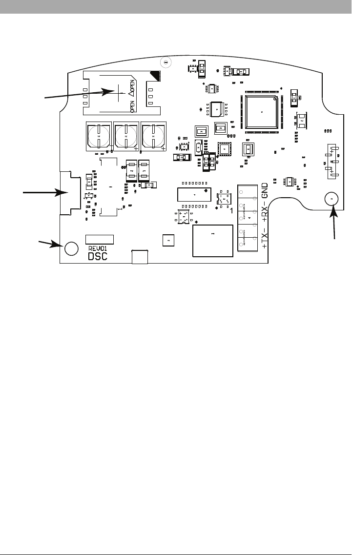
Figure 1: Communication Board Connection Points
Mounting
Hole
Mounting
Hole
SIM Card Holder
RJ-45
Connector
(TL2553G(R)-E only)
UA684
NOTE: The Alarm Communicator is installed in the SCW prior to shipment by Digital Security Controls (DSC). The Factory
Installation includes insertion of the SIM card. The SCW should not be mounted in its final location without performing a
Communicator Test to ensure adequate HSPA/3G coverage for the 3G2055(R)-E and TL2553G(R)-E Alarm Com-
municators
Installation Location
The Communicator shall be installed in an indoor location only.
This HSPA/3G/Ethernet Communicator shall be installed by Service Persons only.(Service Person is defined as a person hav-
ing appropriate technical training and experience necessary to be aware of hazards to which that person may be exposed in
performing a task and of measures to minimize the risks to that person or other persons). The Communicator shall be installed
and used within an environment that provides the pollution degree max 2, over voltages category II, in non-hazardous, indoor
locations only. This manual shall be used with the Installation Manual of the alarm control panel which is connected to the
HSPA/3G/Ethernet Communicator. All instructions specified within the control panel manual must be observed.
All the local rules imposed by local electrical codes shall be observed and respected during installation.
Installing CAT 5 Cable (TL2553G(R)-E only)
A Category 5 (CAT 5) ethernet cable must be run from a source with Ethernet/Internet connectivity to the Communicator mod-
ule, inside the Self Contained Wireless Control Panel cabinet. The Communicator end of the cable must have an RJ-45 plug,
which connects to the Communicator’s RJ-45 jack. All requirements for installation of CAT5 ethernet cable must be observed
for correct operation of the Communicator, including, but not limited to, the following:
lDo NOT strip off cable sheathing more than required for proper termination.
lDo NOT kink/knot cable.
lDo NOT crush cable with cable ties.
lDo NOT untwist CAT5 pairs more than 1.2cm (½”).
lDo NOT splice cable.
lDo NOT bend cable at right angles or make any other sharp bends.
9
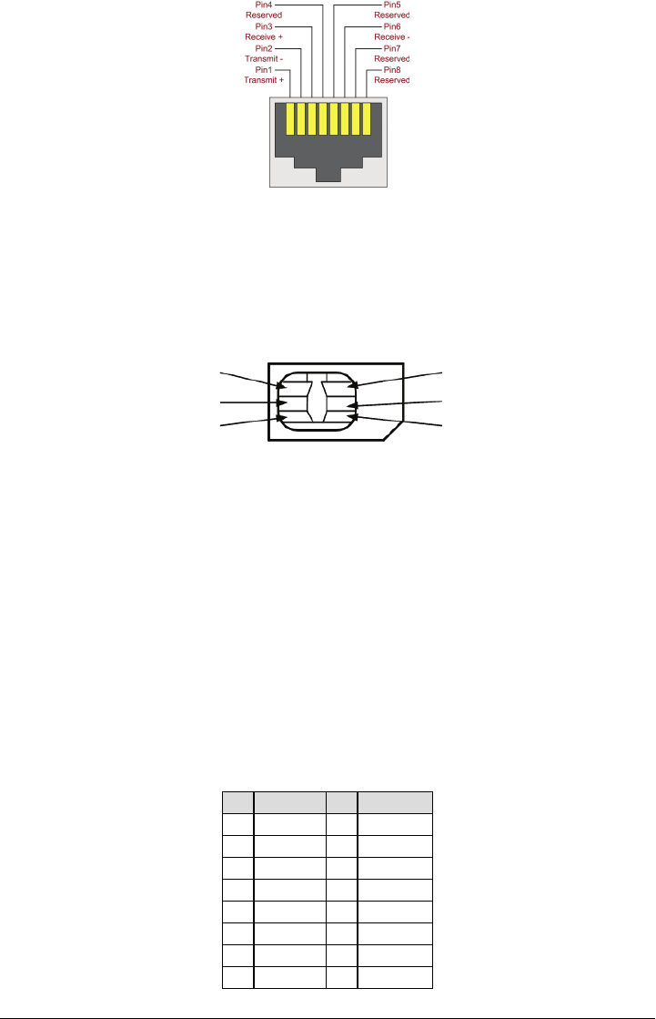
Figure 2: RL-45 Pinout
RJ-45 Connector
NOTE: CAT5 specification requires that any cable bend must have a minimum 5 cm (2 in.) bend radius. Maximum length of
CAT 5 cable is 100m (328 ft.).
NOTE: The Ethernet cable shall not be visible when the installation is complete unless the install is a surface mount installation.
INSERTING/REMOVING THE SIM CARD
Figure 3: SIM Card Pinouts
SIM Card Pinouts
GND
Vpp
I/O
Vcc
Reset
CLK
1. Remove the front cover of the SCW Control Panel to access SIM card holder.
2. Remove power from the SCW and disconnectthe backup batteryconnections.
3. On the SIM card holder push gently to slide the cover towards OPEN as indicated by the arrow on SIM holder. This will
unlatch the SIM card holder on the side furthest from edge of the Communicator. See Figure 1.
4. Lift up the SIM card holder from the side that is not hinged.
NOTE: The SIM card can be damaged by bending or scratching contacts. Use caution when handling the SIM card.
5. Insert or remove the SIM card, noting the orientation of the notches on the SIM card and the SIM card holder.
6. When inserting a SIM card, insert the card in the proper orientation and gently push the SIM card holder down and slide
the holder as indicated by the arrow on SIM holder, to LOCK.
7. Apply AC power to panel, and replace the panel cover.
NOTE: If two way audio is enabled you will NOT be able to swap the SIM card with another card.
Communicator Reset
The Communicator can be reset by cycling the power on the SCW.
Establishing a Communication Channel with the SCW Panel.
The Communicator interfaces to the SCW through a keyed 16 pin Ribbon cable. See Table 6 . The key prevents incorrect con-
nection of the ribbon cable connector to the SCW and Communicator. The pinout for the Ribbon cable is provided in the Table
below:
Table 6: Communicator Ribbon cable to SCW
Pin # Signal Pin # Signal
1 PC-Link TX 2 PC-Link RX
3 GND 4 Vref
5 Vref 6 GND
7 AUD-OUT_N 8 AUD_OUT_P
9 AUD-IN_P 10 AUD-IN_N
11 GND 12 SI
13 GND 14 SO
15 GND 16 Wall Tamper
10

Establishing a communication channel between the Communicator and the SCW is critical to ensuring the desired operation of
the two units. The following steps must be completed during the on-site installation. Program the following to ensure that the
Communicator and the panel will work together as intended.
Initial Programming of Communicator and SCW
1. Enter [*][8][Installer Code] [Section Number] for panel programming. Record any values that are modified from their
default, in the appropriate Programming Worksheets.
NOTE: When programming Toggle Options,the toggle is ON when the number is displayed and OFF when the number is not
dis played. (e.g.,[1---5---],Toggle Options 1 and 5 are ON, all others are OFF).
2. Panel Section [167] Cellular/Ethernet Interface Communications ‘Wait for ACK’: Default value is: 060 seconds.
3. When the communicator is installed with the SCW panel, 4 telephone numbers are available to backup one another.
You can set up these 4 telephone numbers to perform in one of two ways: Backup dialling or Alternate dialling.
a. Backup dialling: each of the 4 telephone numbers will make 5 dialling attempts in turn, before an FTC trouble is dis-
played on the keypad.
b. Alternate dialling: each telephone number makes 1 dialling attempt before moving on to the next number, cycling
through each of the 4 numbers for a total of 5 times each. If all 4 numbers fail the 5 attempts, an FTC trouble is dis-
played on the keypad.
4. Panel Sections [301], [302], [303], and [305] can be configured as Primary communication paths.
a. Panel Sections [302], [303], and [305] may also be configured for backup or redundant communications by using
Panel Section(s) [383] or [351] - [376]. Refer to the SCW panel Installation Manual for more information.
b. If a valid telephone number is programmed, communications will use Public Switched Telephone Network (PSTN).
Entering a 4 digit hexadecimal value for a telephone number will change the call routing to the Communicator, as
determined by the number programmed:
DCAAF: Internal (All Receivers). Signals will be routed depending on Section [851] [006] programming.
DCBBF: Ethernet Receiver 1 (Primary). (Not available for 3G2055(R)-E).
DCCCF: Ethernet Receiver 2 (Backup). (Not available for 3G2055(R)-E).
DCDDF: Cellular Receiver 1 (Primary).
DCEEF: Cellular Receiver 2 (Backup).
NOTE: Add a single ‘F’ as a suffix to the 4 digit hex number to populate the unused remainder of the 32 character field.
5. Panel Section [350]: If any of the phone numbers have been programmed as DCAA, DCBB, DCCC, DCDD, or DCEE,
panel Section [350] must be set to [04] if SIA format or [03] if Contact ID (CID) format is used by control panel.
6. Panel Section [382]: Toggle Option [5], ‘GS/IP Module Enabled’, must be set to ON.
7. Panel Section [401]: Toggle Option [1] must be set to ON in order to perform panel DLS session through Cellular or Eth-
ernet data channel.
8. Panel section [310], account code, auto syncs with the communicator account code in section [021]. The panel account
code ([*][8][installer code] [310]), will overwrite the communicator account code section ([*][8][installer code] [850] [021]) if
programmed differently.
NOTE: Keep a record of the SIM card telephone number, it is required by users for SMS Command and Control functions.
(The number can be recorded in the Programming Worksheets Section of this document, under Option [996]). Due to
the nature of the SIM card activation process with Cellular network carriers, it can take up to 24 hours for SIM card activ-
ation to be complete.
SMS Command and Control Functions
SMS Command and Control is available on SCW9055/57 panels. Users can send SMS text messages from their mobile phone
to the GSM phone number assigned to their system. Commands are only accepted from telephone numbers that have been
programmed in Sections [311]-[318]. The system will reject messages sent from telephone numbers that are not on the pro-
grammed list.
When the received SMS text matches a valid Section message, the function is performed on the control panel. Text messages
are not case sensitive and extra spaces are ignored. A User Access Code may be required for some SMS messages.
The SMS Message format is in 3 parts:Command, Partition Label (or only the partition number), and Access Code.
If an Access Code is included in the message, it is sent to the control panel for validation, along with the requested function.
If the panel is configured to require an Access Code and the code is not sent (or invalid) the panel will fail the function (unsuc-
cessful).
If the panel fails the function, an SMS response message is sent to the user. The SMS response will echo the command sensat,
followed by the label “unsuccessful”. (e.g., “night arm partition 2 1234 unsuccessful”).
The partition label or partition number may be excluded from the SMS request in a single partition system (e.g., disarm 9123).
NOTE: The GSM phone number can be viewed in Section [851] [996], and/or [851] [229] or by entering *6, then scrolling down
to “SMS Programming” and scrolling down to “Cellular phone No”.
Label Programming for SMS Message
Programmable Labels can not be modified in Connect24, use DLS IV for label programming only, if labels need to be mod-
ified. Before initiating remote programming, record your network’s Public IP Address and port for incoming DLS IV con-
nections.
11
1. Run the DLS IV software on your computer. DLS IV will connect to the unit, using the Public IP address, and make an Eth-
ernet connection. If the Ethernet connection fails, DLS IV will report an error and prompt you to connect using Cellular.
NOTE: If required, download the DLS IV software from DSC: http://www.dsc.com/index.php?n=library#self. If you select Cellular
connection, DLS will request Connect24 to send an outgoing SMS message to the unit.
2. Connect24 will confirm that the account has DLS service and will provide the Public IP addressand port number of the
DLS server in an SMS message.
3. SMS message will establish a connection to your computer’s DLS IV software (to change programming labels only).
4. Create an account for the panel/Communicator, select the Communicator type (e.g., SMS - TL2553GR-E) and enter all
relevant information in SMS section.
NOTE: The Cellular telephone number will also be required by the user, to send SMS Command and Control messages to
their system.
5. Program the account information, then click Global Download and choose SMS as the Connection Type. Click OK.
6. The download path configured in Programming Section [005] Toggle Option[4] determines the Cellular or Ethernet path
to be used.
Communicator Placement Test
(3G2055(R)-E / TL2553G(R)-E only)
1. Using the keypad enter the installer mode: [*][8] [installer code] [850].
2. View and record the number of bars showing on the SCW LCD.
3. Compare with the number of bars indicated in the “CSQ Levels” column shown in Table 7 .
4. If 3 or more bars are shown, the location is GOOD and no further action is required.
5. If the location is BAD,move the SCW to various suitable locations until 3 or more bars are obtained.
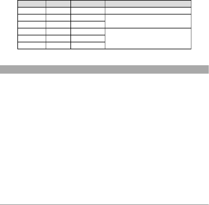
Table 7: Communicator CSQ Levels
Signal Strength CSQ Level Signal Level (dBm) Installer Action
No Signal 0 -108.8 Check if Cellular coverage is active in your area.
1 Bar 1 to 4 -108 to -103 Location is BAD. Not suitable for Cellular operation.
2 Bars 5 to 6 -102 to -99
3 Bars 7 to 10 -98 to -90
Location is GOOD.4 Bars 11 to 13 -90 to -85
5 Bars 14 and higher -84 and higher
NOTE: The communicator is capable of indicating signal strength even without an active SIM, but signal indication may take up
to 1-2 minutes.
Ethernet/Cellular Programming Options
The Programming Sections described in this document can be viewed at the SCW LCD. To start programming enter: [*][8]
[installer code] [851][###], Where ### is the 3 digit Section number referenced in this section. The Programming Worksheets at
the end of this document can be used to record the new values when programming changes have been made from the default
values. Programming Sections are accessed through Connect24. Installers may review/record programming Options at the
panel.
NOTE: Ethernet/Cellular Programming Sections accessed through the panel are for display purposes only. Configuration
changes must be done using Connect24.
System Options
[001] Ethernet IP Address
Default (000.000.000.000)
Enter the IP address of the Communicator. Ensure that the IP address is unique to your Communicator on the local network.
Format is 4 fields, each field is a 3 digit decimal number. Valid range: 000-255. If an IP address is programmed in this Section,
the unit will operate with Static IP (DHCP disabled). Sections [002] and [003] must also be programmed when using Static IP
addresses.
NOTE: Default for this Section is Dynamic Host Configuration Protocol (DHCP) enabled. When enabled, the DHCP Server will
set values for: IP Address [001], Subnet Mask [002], and Gateway [003]. Programming an IP address in this Section will
disable DHCP (Static IP).
[002] Ethernet IP Subnet Mask
Default (255.255.255.000)
Enter the Ethernet IP Subnet Mask of the Communicator. Format is 4 fields, each field is 3 digits. Valid range: 000-255.
NOTE: If DHCP is enabled, the DHCP Server will assign the subnet mask for this Section and the programmed value will be
ignored.
12

[003] Ethernet Gateway IP Address
Default (000.000.000.000)
Enter the Ethernet Gateway IP address of the Communicator. The gateway IP address is required when a router is used on the
local network to reach the destination IP address specified in Section [001]. Format is 4 fields, each field is a 3 digit decimal
number. Valid range: 000-255.
NOTE: If DHCP is enabled, the DHCP Server will assign the Gateway IP addressfor this Section and the programmed value
will be ignored.
[004] Receiver Supervision Interval
Default (0087/135)
When receiver supervision is enabled (ON) in Section [005] Toggle Option [3], the unit sends heartbeats to Ethernet Receiver
1 or Cellular Receiver 1 to test the communications path. Use this Section to set the interval time (in seconds) when heartbeats
will be sent to the receivers. Valid range 000A-FFFF seconds. If the programmed value is less than (000A/10) seconds, super-
vision is disabled.
lReceiver Window: This is the supervision timeout that must be configured at the central station receiver.
lRecommended Values: This is the recommended heartbeat interval that should be programmed into the Communicator.
lFor ULC installations, the Daily test transmission must be enabled over each available communication channel Sections
[125] and [225]. When programming with Connect24, the recommended intervals will be programmed automatically when
the required window is selected.
[005] System Toggle Options
[1] Ethernet Receiver 1 Supervised
Default (OFF)
(TL2553G(R)-E only).
ON: Ethernet Receiver 1 will be supervised and heartbeatswill be sent to Ethernet Receiver 1 based on the supervision inter-
val programmed in Section [004].
OFF: Ethernet Receiver 1 will not be supervised. When disabled, heartbeat 1 is sent to the Ethernet receiver once every hour,
regardless of supervision type (heartbeat 1 or 2). The heartbeat is resent every 5 seconds until ACK. If no event or heartbeat
ACK is received after (Receiver Supervision Interval + 75 seconds), Supervisory trouble is indicated.
NOTE: Ethernet Receiver 2 can not be supervised.
[2] Cellular Receiver 1 Supervised
Default (OFF)
ON: Cellular Receiver 1 will be supervised and heartbeats will be sent to Cellular Receiver 1 based on the supervision interval
programmed in Section [004]. If ACK to heartbeat is not received, it is retransmitted every 5 seconds. Failure to ACK 2 con-
secutive heartbeats will reset the radio.
OFF: Cellular Receiver 1 will not be supervised. When disabled, heartbeat is not sent to the receiver. Supervisory trouble is
indicated.
NOTE: Cellular Receiver 2 can not be supervised.
[3] Supervision Type
Default (OFF)
ON: Heartbeat 1 (Commercial Supervision). This supervision type is suitable for applications where swap detection is required
on the supervisory packet.
OFF: Heartbeat 2 (Residential Supervision). This supervision type is suitable for applications where supervision of the com-
munication path to the receiver is required. (no swap detection).
NOTE: Commercial supervision is more data intensive than residential supervision and should only be used when required to
meet the approval for the installation.
[4] Primary Path
Default (OFF - TL2553G(R)-E) (ON - 3G2055(R)-E)
ON: Cellular channel is the primary path. Ethernet channel is the secondary path, if it exists.
OFF: Ethernet channel is the primary path in a dual Communicator. Cellular channel is the secondary path.
[5] Redundant Communications
Default (OFF) (TL2553G(R)-E only)
ON: Events will be communicated to Ethernet Receiver 1 and Cellular Receiver 1 at the same time. Events will be com-
municated to Ethernet Receiver 2 and Cellular Receiver 2 at the same time. As long as the event is successfully communicated
to 1 of the 2 paths (Ethernet or Cellular) the Communicator will move on to the next event.
NOTE: Do not configure Ethernet Receiver 1 and Cellular Receiver 1 to communicate using a common receiver configuration
(i.e., identical Receiver IP address and Receiver Remote Port). OFF: Events will be communicated to the receivers indi-
vidually. Toggle should be OFF when guaranteed message delivery to both receivers is required.
[6] Remote Firmware Upgrade
Default (ON)
ON: The Communicator module firmware can be remotely upgraded using the Ethernet/Cellular paths.
OFF: The Communicator module firmware can not be remotely upgraded. Local firmware upgrade is still possible.
[7] Alternate Test Transmissions
Default (OFF).
13

ON: When the periodic test transmission interval occurs, the test transmission will alternate between being sent to the primary
and secondary receivers with each test transmission interval.
OFF: When the periodic test transmission interval occurs, the test transmission will be sent to the programmed receivers, based
on the settings of the periodic test transmission reporting codes.
[8] Cellular Low Signal Trouble.
Default (OFF)
This option masks the Low Signal trouble from the Cellular trouble event.
ON: A Cellular Trouble event is transmitted to receiver when the radio signal level falls below threshold level (average CSQ
level is 4 or less).
OFF: A Cellular Trouble event is not transmitted to receiver when the radio signal level falls below threshold level (average
CSQ level is 4 or less).
[006] System Toggle Options 2
[1] Ethernet 1 Receiver Enabled.
Default (ON) (OFF for 3G2055(R)-E).
ON: Ethernet Receiver 1 is enabled.
OFF: Ethernet Receiver 1 is disabled.
[2] Ethernet 2 Receiver Enabled.
Default (ON) (OFF for 3G2055(R)-E).
ON: Ethernet Receiver 2 is enabled.
OFF: Ethernet Receiver 2 is disabled.
[3] Reserved. ( ).
[4] Cellular 1 Receiver Enabled.
Default (ON).
ON: Cellular Receiver 1 is enabled.
OFF: Cellular Receiver 1 is disabled.
[5] Cellular 2 Receiver Enabled.
Default (ON).
ON: Cellular Receiver 2 is enabled.
OFF: Cellular Receiver 2 is disabled.
[6] Reserved ( ).
[7] DLS Over Cellular.
Default (ON).
NOTE: Program this toggle as OFF if you want to completely disable DLS from using the Cellular path.
ON: DLS is enabled on the Cellular path.
OFF: DLS is disabled on the Cellular path.
NOTE: If this Toggle is OFF, DLS sessions will occur on the Ethernet path only, regardless of Primary Path set in Section [005]
Toggle Option [4]. If it is ON then the Communicator will connect to the Primary path first for DLS and if the session fails,
the Secondary path will be used.
[8] Reserved ( ).
[007] DNS Server IP 1
Default (000.000.000.000)
Programming this Section is not permitted on a UL/ULC listed system.
Enter the IP address for DNS Server 1. Format is 4 fields, each field is a 3 digit decimal. Valid range: 000-255.
NOTE: If no value is programmed and DHCP is used, the DHCP Server will configure the address. If an address is pro-
grammed and DHCP is used, the address that you program will be used instead of the DHCP address.
[008] DNS Server IP 2
Programming this Section is not permitted on a UL/ULC listed system.
Default (000.000.000.000)
Enter the IP address for DNS Server 2. Format is 4 fields, each field is a 3 digit decimal. Valid range: 000-255.
NOTE: Ifno value is programmed and DHCP is used, the DHCP Server will assign this value. If an address is programmed and
DHCP is used, the address that you program will be used instead of the DHCP address.
Programming Options
[010] System Toggle Option
Default (Disable)
[1] This bit is used to enable/disable two way audio over 3G.
[011] Installer Code
Default (CAFE)
Program your installer code for this Communicator module. The installer code will be required when programming the Com-
municator module. Valid range: 0000 - FFFF.
14

[012] DLS Incoming Port
Default (0BF6/3062)
The DLS Incoming Local Port (listening port) is the port DLS IV will use when connecting to the Communicator. If a router or
gateway is used, it must be programmed with a Transmission Control Protocol (TCP) port forward for this port to the Com-
municator module IP address. Valid range: 0000 - FFFF.
[013] DLS Outgoing Port
Default (0BFA/3066)
The DLS Outgoing Port is used for outgoing session to DLS IV after an SMS request has been sent to the Communicator. Use
this Section to set the value of the local outgoing port.The value mustbe changed if the Communicator is located behind a fire-
wall and must be assigned a particular port number, as determined by your network administrator. In most cases, changing the
default value or configuring your firewall with this port is not required.
Valid range: 0000-FFFF.
NOTE: If Section [006] Toggle Option [7] is ON, DLS will use the Primary path for session. If Section [006] Toggle Option [7] is
OFF DLS will use the Ethernet path, if available.
[020] Time Zone
Default (00)
Use Column 2 (Offset Hours) to find your local Time Zone. Record the two digit HEX value from Column 1 (HEX Value) on the
same row. Program this HEX value for your Time Zone. Valid range is 00 - FF.
Table 8: World Wide Time Zones
HEX
Value
Offset
Hours
Standard
Abbreviation Location
01 -12 BIT Baker Island Time
05 -11 SST Somoa Standard Time
09 -10 HAST Hawaii-Aleutian Standard Time
0B -9.5 MIT Marquesas Island Time
0D -9 AKST Alaska Standard Time
11 -8 PST Pacific Standard Time
15 -7 MST Mountain Standard Time
19 -6 CST Central Standard Time
1D -5 EST Eastern Standard Time
1F -4.5 VST Venezuela Standard Time
21 -4 AST Atlantic Standard Time
23 -3.5 NST Newfoundland Standard Time
25 -3 ART Argentina Time
29 -2 BEST Brazil Eastern Standard Time
2D -1 CVT Cape Verde Time
31 0 GMT Greenwich Mean Time (UTC)
35 1 CET Central European Time
39 2 SAST South Africa Standard Time
3D 3 AST Arabic Standard Time
3F 3.5 IRST Iran Standard Time
41 4 GST Gulf Standard Time
43 4.5 AFT Afghanistan Time
45 5 PKT Pakistan Time
47 5.5 IST Indian Standard Time
48 5.75 NPT Nepal Time
49 6 VOST Vostok Time
4B 6.5 MMT Myanmar Time
15

HEX
Value
Offset
Hours
Standard
Abbreviation Location
4D 7 BDT Bangladesh Standard Time
51 8 CST China Standard Time
52 8.25 APO Apo Island Time
54 8.75 ACWST Australian Central Western Standard Time
55 9 KST Korea Standard Time
57 9.5 ACST Australian Central Standard Time
59 10 AEST Australian Eastern Standard Time
5B 10.5 LHST Lord Howe Standard Time
5D 11 VUT Vanuatu Time
5F 11.5 NFT Norfolk Island Time
61 12 NZST New Zealand Standard Time
64 12.75 CHAST Chatham Island Standard Time
65 13 TOT Tonga Time
69 14 LINT Line Island Time
70-FF N/A N/A N/A
[021] Account Code
Default (FFFFFF)
The account code is included when transmitting any events generated by the Communicator. (e.g., Panel Absent Trouble). It is
recommended that the account code be the same as the control panel account number. Valid range: 000001-FFFFFE. If 4 digit
account codes are needed the 2 lowest digits shall be programmed as FF.
(e.g., Account 1234 is programmed as:1234FF).
NOTE: Programming this Section with all 0 or F will cause a Module Configuration Trouble.
[022] Communications Format
Default (04)
Program 03 for Contact ID (CID). Program 04 for SIA. The module can be configured to send Events in SIA or CID format. The
SIA communication format follows the level 2 specifications of the SIA Digital Communication Standard - October 1997. This
format will send the account code along with its data transmission. The transmission will look similar to the following at the
receiver. Example: Nri0 ET001
Where: N= New Event; ri0 = Partition/Area identifier; ET = Panel Absent Trouble; 001 = Zone 001.
Communications Reporting Codes
Table 9: Communications Reporting Codes
Event SIA
Identifier
SIA
Reporting Code
CID
Qualifier
CID
Event Code
CID
Reporting Code
CID
User/ Zone
[023] Panel Absent Trouble ET 001 1 3 55 001
[024] Panel Absent Trouble Restore ER 001 3 3 55 001
[025] Radio Activation Restore RS 001 3 5 52 001
[026] Ethernet 1 Test Transmission RP 001 1 6 A3 951
[027] Ethernet 2 Test Transmission RP 002 1 6 A3 952
[028] Cellular 1 Test Transmission RP 003 1 6 A3 955
[029] Cellular 2 Test Transmission RP 004 1 6 A3 956
[030] FTC Restore YK 001 3 3 54 001
[023] Panel Absent Trouble
Default (FF)
Program 00 to disable this event or FF to enable. This event will occur when communications with the panel have been lost for
more than 60 seconds.
[024] Panel Absent Trouble Restore
Default (FF)
16

Program 00 to disable this event or FF to enable. This event will occur when communications with the control panel have
resumed.
[025] Radio Activation Restore
Default (FF)
Program 00 to disable this event or FF to enable. This event will occur after any successful Connect24 programming session.
System Test Options [026 - 029]
Test Transmissions to Primary Receiver, with Backup to Secondary Receiver:
Set Ethernet Section [026] to (FF); [027] to (00). Set Cellular Section [028] to (FF); [029] to (00).
lIf the test transmission fails to the primary receiver it will backup to the secondary receiver.
lIf the test transmission fails to the secondary receiver an FTC trouble will be generated.
Test Transmission Unique to Primary and Secondary Receivers:
Set Ethernet Section [026] to (FF); [027] to (FF). Set Cellular Section [028] to (FF); [029] to (FF).
lThe module will send periodic test transmissions to each receiver independently, with no backups.
lIf the test transmission fails to any of the programmed receivers, an FTC trouble will be generated.
Alternate Test Transmission:
Alternate Test Transmission can be enabled or disabled in Section [005] Toggle Option [7].
[026] Ethernet 1 Transmission
Default (FF)
Program 00 to disable this event transmission or FF to enable. See System Test Options (above) for details on settings.
[027] Ethernet 2 Transmission
Default (00)
Program 00 to disable this event transmission or FF to enable. See System Test Options (above) for details on settings.
[028] Cellular 1 Transmission
Default (FF)
Program 00 to disable this event transmission or FF to enable. See System Test Options (above) for details on settings.
[029] Cellular 2 Transmission
Default (00)
Program 00 to disable this event transmission or FF to enable. See System Test Options (above) for details on settings.
NOTE: The time interval (in minutes) between periodic tests is programmed in Section [125] (Ethernet) and Section [225] (Cel-
lular).
[030] FTC Restore
Default (FF)
Program 00 to disable this event transmission or FF to enable. This event will occur when an FTC Trouble on the system
restores.
[031] Priority Tamper Alarm
Program 00 to disable this event or FF to enable. This event will occur when panel tampered during the entry delay.
[032] Priority Tamper Restore
Program 00 to disable this event or FF to enable.This event will occur when panel tamper restored.
Table 10: Priority Temper Restore
Event SIA
Identifier
SIA Reporting
Code
Contact ID
Qualifier
Contact ID
Event Code
Contact ID
Reporting Code
Contact ID
User/Zone
Priority Tamper BA 000 1 1 37 000
Priority Tamper Restore BR 000 3 1 37 000
[033] Communicator Firmware Update Begin
Default (FF);
Program 00 to disable this event transmission or FF to enable. This event will occur when the communicator firmware update
begins.
[034] Communicator Firmware Update Successful
Default (FF);
Program 00 to disable this event transmission or FF to enable. This event will occur when the communicator firmware update
successfully completed.
[035] Panel Firmware Update Begin
Default (FF);
17

Program 00 to disable this event transmission or FF to enable. This event will occur when the panel firmware update begins.
[036] Panel Firmware Update Successful
Default (FF);
Program 00 to disable this event transmission or FF to enable. This event will occur when the panel firmware is updated suc-
cessfully.
[037] Panel Firmware Update Fail
Default (FF);
Program 00 to disable this event transmission or FF to enable. This event will occur when the panel firmware updated has
failed.
Table 11: Panel Tamper Alarm Restore
Event SIA
Identifier
SIA
Reporting
Code
Contact ID
Qualifier
Contact ID
Event Code
Contact ID
Reporting
Code
Contact ID
User/Zone
[033]Comm. FW Update Begin LB 00 1 9 03 002
[034]Comm. FW Update Successful LS 00 3 9 03 002
[035]Panel FW Update Begin LB 00 1 9 03 003
[036]Panel FW Update Successful LS 00 3 9 03 003
[037]Panel FW Update Fail LU 00 1 9 04 003
Ethernet Receiver 1 Options
[101] Ethernet Receiver 1 Account Code
Default (0000000000)
The account code is used by the central station to distinguish between transmitters. This account code is used when trans-
mitting heartbeat signals to the central station receiver. Signals received from the Panel will use the control panel account num-
ber. Valid range: 0000000001-FFFFFFFFFE. Programming all 0 or all F will cause a Module Configuration Trouble.
NOTE: If Ethernet Receiver 1 and Cellular Receiver 1 are programmed as the same receiver (IP and port number are
identical), Ethernet Receiver 1 account code will be used.
[102] Ethernet Receiver 1 DNIS
Default (000000)
The Dialled Number Information Service (DNIS) is used in addition to the Account Code to identify the Communicator module
at the central station. Valid range: 000000 - 099999. Value is entered as a leading 0 followed by the 5 digit DNIS. Format is Bin-
ary Coded Decimal (BCD).
NOTE: Each Ethernet/Cellular receiver must be programmed with a unique DNIS.
[103] Ethernet Receiver 1 Address
Default (127.000.000.001)
The default address enables the Communicator to operate in Unattended Mode.
Unattended Mode is used when a receiver is not available and the unit is required to perform DLS sessions. Typically used
where the customer programs the control panel daily due to access control and still wants to receive alarms without buying
extra hardware (receiver) or software.
NOTE: When a valid IP address has been programmed, Ethernet Receiver 1 is enabled and will communicate events over the
Ethernet channel.
Ethernet Receiver 1 and Cellular Receiver 1 may be configured to communicate to the same central station receiver. To con-
figure the device to operate using this Common Receiver Mode functionality, program Ethernet Receiver 1 and Cellular
Receiver 1, IP address and port number with identical values.
NOTE: When operating in Common Receiver Mode, Ethernet Receiver 1 account code will be used for Ethernet and Cellular.
[104] Ethernet Receiver 1 Remote Port
Default (0BF5/3061)
This Section determines the remote port of Ethernet receiver 1. Valid range: 0000 - FFFF.
[105] Ethernet Receiver 1 Local Port
Default (0BF4/3060)
Use this Section to set the value of the local outgoing port. Set the value of this port when your installation is located behind a
firewall and must be assigned a particular port number as determined by your central station
system administrator. Valid range: 0000 - FFFF.
[106] Ethernet Receiver 1 Domain Name
Default ( )
18

Enter the Domain Name as 32 ASCII characters.
Programming this Section is not permitted on a UL/ULC listed system.
Ethernet Receiver 2 Options
[111] Ethernet Receiver 2 Account Code
Default (0000000000)
The account code is used by the central station to distinguish between transmitters. The account code is used when transmitting
heartbeat signals to the central station receiver. Signals received from the control panel will use the control panel account num-
ber. Valid range: 0000000001- FFFFFFFFFE. Programming all 0 or all F will cause a Module Configuration Trouble (yellow
LED=12 flashes).
NOTE: Ifboth Ethernet Receiver 2 and Cellular Receiver 2 are the same receiver (IP and port number are identical), Ethernet
Receiver 2 account will be used for Ethernet and Cellular.
[112] Ethernet Receiver 2 DNIS
Default (000000)
The DNIS is used in addition to the account code to identify the Communicator module at the central station. Valid range:
000000 - 099999. Value is entered as leading 0 followed by the 5-digit DNIS. Format is BCD.
NOTE: Each Ethernet/Cellular receiver must be programmed with a unique DNIS.
[113] Ethernet Receiver 2 Address
Default (000.000.000.000)
Programming the Ethernet receiver 2 IP address with 000.000.000.000 will disable Ethernet.
Enter the Ethernet receiver 2 IP address. This address will be provided by your central station system administrator. Format is 4
fields, each field is a 3-digit decimal. Valid range: 000-255.
NOTE: When a valid IP address has been programmed, Ethernet Receiver 2 is enabled and will communicate events over the
Ethernet channel.
Ethernet Receiver 2 and Cellular Receiver 2 may be configured to communicate to the same central station receiver.
To configure the device to operate using this common receiver mode functionality, program the Ethernet Receiver 2 and Cel-
lular Receiver 2, IP address and port number with the same values. When operating in common receiver mode the Ethernet
Receiver 2 account code will be used for communications over Ethernet and Cellular.
NOTE: Do not program Ethernet Receiver 1 and Ethernet Receiver 2 to communicate to same receiver.
[114] Ethernet Receiver 2 Remote Port
Default (0BF5/3061)
This Section is used to program the port number used by Ethernet Receiver 2. Set the value of this port when your installation
is located behind a firewall, and mustbe assigned a particular port number as determined by your central station system admin-
istrator. Valid range: 0000 - FFFF.
NOTE: Do not program Ethernet Receiver 1 and Ethernet Receiver 2 Port with the same value.
[115] Ethernet Receiver 2 Local Port
Default (0BF9/3065)
Use this Section to program the value of the local outgoing port. You can set the value of this port when your installation is loc-
ated behind a firewall and must be assigned a particular port number as determined by your network administrator. Valid
range: 0000 - FFFF.
NOTE: Do not program Ethernet Receiver 1 and Ethernet Receiver 2 Port with the same value.
[116] Ethernet Receiver 2 Domain Name
Default ( )
Programming this Section is not permitted on a UL/ULC listed system.
Enter the Domain Name as 32 Character ASCII.
Ethernet Options
[124] Ethernet Test Transmission Time
Default (9999)
Enter a 4 digit number (0000-2359) using the 24-hour clock format (HHMM) to set the testtransmission time of day.
Valid range: 00 - 23 hours (HH) and 00 - 59 minutes (MM). Programming a value of 9999 will disable the test transmission
time.
NOTE: The internal date and time will automatically be programmed when the unit communicates with the primary receiver.
[125] Ethernet Test Transmission Cycle
Default (000000)
This value represents the interval between test transmissions, in minutes. Valid range: 000000 - 999999 minutes. Once the unit
has sent the initial periodic test transmission, all future test transmissions will be offset by the programmed number of minutes.
See Sections [026] - [029].
19

Table 12: Ethernet Test Transmission Interval
Test Transmission Interval Daily Weekly Monthly
Programmed Minutes 001440 010080 043200
NOTE: Minimum value is 000005 minutes. Programming an interval that is less than 5 minutes will disable test transmission.
Cellular Receiver 1 Options
[201] Cellular Receiver 1 Account Code
Default (0000000000)
The account code is used by the central station to distinguish between transmitters. This account code is used when trans-
mitting heartbeat signals to the central station receiver. Signals received from the control panel will use the control panel
account number. Valid range: 0000000001 - FFFFFFFFFE. Programming all 0 or all F will cause a Module Configuration
Trouble (yellow LED = 12 flashes).
[202] Cellular Receiver 1 DNIS
Default (000000)
The DNIS is used in addition to the account code to identify the Communicator module at the central station. Valid range:
000000 - 099999. Values are entered as leading 0 followed by the five digit DNIS. Format is BCD.
NOTE: Each Ethernet/Cellular receiver must be programmed with a unique DNIS.
[203] Cellular Receiver 1 Address
Default (000.000.000.000)
Enter the Cellular Receiver 1 IP address. This information will be provided by your central station system administrator. Each 3-
digit segment of the address must be within a valid range of 000-255.
NOTE: When a valid IP address has been entered, the Cellular is enabled and will communicate eventsover the Cellular chan-
nel.
[204] Cellular Receiver 1 Port
Default (0BF5/3061)
This Section determines the port used by Cellular Receiver 1. Change the default value of this port when your installation is loc-
ated behind a firewall, and must be assigned a particular port number as determined by your central station system admin-
istrator. Valid range: 0000 - FFFF.
NOTE: Programming this Section with 0000 will disable the receiver.
[205] Cellular Receiver 1 APN
Default ( )
The Access Point Name (APN) determines the Cellular network that the Communicator will connectto. This information is avail-
able from your network carrier. Program this Section as 32 ASCII characters.
NOTE: When a SIM card with a custom APN is used, the unit will not have access to the Internet. DLS and remote flash can still
be done if Section [221] is programmed with a valid Public APN.
[206] Cellular Receiver 1 Domain Name
Default ( )
Programming this Section is not permitted on a UL/ULC listed system.
Enter the Domain Name as 32 ASCII characters.This information will be provided by your central station system administrator.
Cellular Receiver 2 Options
[211] Cellular Receiver 2 Account Code
Default (0000000000)
The account code is used by the central station to distinguish between different transmitters. This account code is used when
transmitting signals to the central station receiver. Signals received on the panel will use the panel account number. Valid
range: 0000000001 - FFFFFFFFFE.
NOTE: Programming this Section as all 0 or F will cause a Module Configuration Trouble (yellow LED = 12 flashes).
[212] Cellular Receiver 2 DNIS
Default (000000)
The DNIS is used in addition to the Account Code to identify the Communicator module at the central station. Valid range:
000000 - 099999. Values are entered as a 0 followed by the 5 digit DNIS value. Format is BCD.
NOTE: Each Ethernet/Cellular receiver must be programmed with a unique DNIS.
[213] Cellular Receiver 2 Address
Default (000.000.000.000)
Enter the Cellular Receiver 2 IP address. This IP address will be provided by your central station. Format is 4 fields, each field is
3-digit decimal. Valid range: 000 - 255.
20

NOTE: When a valid address has been entered, Cellular Receiver 2 is enabled and will communicate events over the Cellular
path.
[214] Cellular Receiver 2 Port
Default (0BF5/3061)
This Section defines the port of Cellular Receiver 2. Change the value of this port when your installation is located behind a fire-
wall and must be assigned a particular port number, as determined by your central station system administrator. Valid range:
0000 - FFFF.
NOTE: Do not program Cellular Receiver 1 and Cellular Receiver 2 to communicate to the same receiver.
[215] Cellular Receiver 2 APN
Default ( )
The APN determines the Cellular network that the Communicator will connect to. This information is available from your net-
work carrier. Program this Section with up to 32 ASCII characters.
NOTE: When a SIM card with a custom APN is used, the unit will not have access to the internet. DLS and remote flash can still
be done if Section [221] is programmed with a valid Public APN.
[216] Cellular Receiver 2 Domain Name
Default ( )
Programming this Section is not permitted on a UL/ULC listed system.
Enter the Cellular Receiver 2 Domain Name with up to 32 ASCII characters.
Cellular Options
[221] Cellular Public Access Point Name
Default ( )
When the Communicator is operating on a private APN, use this Section to select a public APN for DLS and Remote Firmware
Update. This information is available from your network carrier. The APN identifies the public Cellular network that the Com-
municator will connect to.
[222] Cellular Login User Name
Default ( )
Some network carriers require you to provide login credentials when connecting to an APN. Program your login User Name in
this Section. Format is up to 32 ASCII characters.
NOTE: This Section is not accessible via SCW keypad programming.
[223] Cellular Login Password
Default ( )
Some network carriers require you to provide login credentials when connecting to an APN. Program your login Password in
this Section.
Format is up to 32 ASCII characters.
[224] Cellular Test Transmission Time of Day
Default (9999)
Enter a 4 digit value using the 24-hour clock format (HHMM) to set the test transmission time of day. Valid range: 00-23 for the
hours (HH) and 00-59 for the minutes (MM).
NOTE: To disable the test transmission time of day enter 9999 or FFFF in this Section.
The internal date and time will be automatically programmed by the primary receiver only.
[225] Cellular Test Transmission Cycle
Default (000000)
This value represents the interval in between test transmissions in minutes. Valid range: 000000 - 999999 minutes. Once the
unit has sent the initial periodic test transmission, all future test transmissions will be offset by the programmed number of
minutes. See Sections [026] - [029].
Table 13: Cellular Test Transmission Interval
Test Transmission Interval Daily Weekly Monthly
Programmed Minutes 001440 010080 043200
NOTE: Minimum value is 000005 minutes. Programming an interval that is less than 5 minutes will disable test transmission.
[226] Cellular Trouble Delay
Default (00)
This option is used to program the delay, in minutes, for reporting a Cellular Trouble Delay. Valid entries are 00 - FF. (e.g., for a
10 minute Cellular Trouble Delay enter: 0A). There is no reporting delay if value is programmed as 00.
21

[227] Voice Call Timeout
Default (00);
This option sets the Voice Call Timeout, in minutes. Programming a value of 00 will disable timeout. Valid range is 00 to FF.
[228] Voice Call Back Time
Default (0A);
This option sets the Voice call back time, in minutes. When the Communicator requests Call Back from the receiver, it will
answer incoming calls during the programmed timeout period. If an incoming call is received after the timeout from requesting
call back, the Communicator will answer the call and immediately hang up. Programming a value of 00 will disable timeout
(accept all incoming calls). Default value is 0A/10 seconds.Valid range is 00 to FF.
[229] Voice Call Back Number
Default (SIM Telephone Number);
This option sets the Voice Call Back Telephone Number for the receiver. This number is used for Two Way calling. Current SIM
telephone number can be viewed in Section [996]. Valid entry is 32 character ASCII.
Command and Control Options
[301] Command and Control Toggle Options
[1] SMS Notification Default (ON).
[2] Reserved Default ( ).
[3] SMS Command and Control Default (ON).
[4] Reserved Default ( ).
[5] SMS Character Format Default.
ON: SMS Unicode, maximum message length is 70 characters.
OFF: 7 bit SMS, maximum message length is 160 characters.
[6] Long SMS Message Handling Default (OFF).
ON: If longer than maximum message length, it is split and sent as multiple SMS messages.
OFF: If longer than maximum message length, a single, truncated SMS message is sent.
[7-8] Reserved Default ( ).
[311] - [318] SMS Phone Number 1 - 8
Default ( );
These Sections may be programmed through DLS IV or the keypad. Up to 8 SMS telephone numbers (4 - 32 digits) can be pro-
grammed in Section [31x]Where x is an SMS telephone number from 1 to 8. Leaving programming blank for a telephone num-
ber will disable that number. The User can program their own mobile telephone numbers at the keypad using [*] [6] <> “SMS
Programming”. The SMS Command and Control feature utilizes the SMS messaging service provided by the Cellular network
and is subject to the limitations of SMS messaging. These limitations include delayed messages and lack of guaranteed deliv-
ery.
NOTE: SMS Command and Control (Sections [601] - [618] will only process messages from the mobile telephone numbers pro-
grammed in this Section if SMS Command and Control is enabled [301][ 3] ON. SMS responses are listed in Sections
[621] - [630]. A blank telephone number is disabled.
SMS Command and Control Functions
Users can send SMS text messages from their mobile phone to the communicator cellular phone number assigned to their sys-
tem. Commands are only accepted from telephone numbers that have been programmed in Sections [311]-[318]. The system
will reject messages sent from telephone numbers that are not on the programmed list.
When the received SMS text matches a valid Section message, the function is performed on the control panel. Text messages
are not case sensitive and extra spaces are ignored. A User Access Code may be required for some SMS messages.
The User can send just the partition number or the complete label.(e.g., “Away arm Partition 2 1234” is treated the same as
“away arm 2 1234”).
The SMS Message format is in 3 parts:Command, Partition Label (or only the partition number), and Access Code.
lIf an Access Code is included in the message, it is sent to the control panel for validation, along with the requested function.
lIf the panel is configured to require an Access Code and the code is not sent (or invalid) the panel will fail the function
(unsuccessful).
lIf the panel fails the function, an SMS response message is sent to the user. The SMS response will echo the command
sent, followed by the label “unsuccessful”. (e.g., “night arm partition 2 1234 unsuccessful”).
lThe partition label or partition number may be excluded from the SMS request in a single partition system (e.g., disarm
9123).
NOTE: The communicator cellular phone number can be viewed in Section [851], [996] and/or [851], [229] or by user entering
[*][6], then scrolling down to ‘SMS Programming” and scrolling down to “Cellular phone No.” [<] [>] “Cellular Phone
No.” at the keypad. An Access Code is required for all SMS commands, except Help.
[601] Stay Arm
Default (Stay Arm);
22

Send this command to the system to stay arm. It may be followed by a Partition Label or partition number and Access Code.
[602] Away Arm
Default (Away Arm);
Send this command to the system to away arm. Itmay be followed by a Partition Label or partition number and Access Code.
[603] Night Arm
Default (Night Arm);
Send this command to the system to night arm.It may be followed by a Partition Label or partition number and Access Code.
[604] Disarm
Default (Disarm);
Send this command to the system to disarm. It may be followed by a Partition Label or partition number and Access Code.
[605] - [608] Activate Command Output 1 - 4
Default (Activate Command Output n);
Where n is a number from 1 - 4. Send this command to the system to activate a command output.It may be followed by a Par-
tition Label or partition number and Access Code.
[609] - [612] Deactivate Command Output 1 - 4
Default (Deactivate Command Output n);
Where n is a number from 1 - 4. Send this command to the system to deactivate a command output.This command may be fol-
lowed by a Partition Label or partition number and optional Access Code.
[613] Bypass
Default (Bypass);
Send this command to the system to bypass a Zone. This command should be followed by a Zone label or Zone number and
Access Code.
[614] Unbypass
Default (Unbypass);
Send this command to the system to unbypass a Zone. This command should be followed by the Zone label or Zone number
and Access Code.
[615] Status Request
Default (Status Request);
Send this command to request the status of the system. It may be followed by a partition label or partition number and Access
Code. If partition label is omitted, status of all enabled partitions will be sent. If there is a trouble on the system, the system label
is sent,followed by the trouble label, then the partition status.
NOTE: Status Request response may require more than one SMS message, depending on status of the system. There is a 10-
second delay between transmission of SMS messages.
[616] Alarm Memory Request
Default (Alarm Memory Request);
Send this command to the system to request the alarm memory from the system. This command may be followed by a Partition
Label or partition number, and Access Code. If partition label is omitted, alarm memory of all partitions will be sent. Alarm
memory responses will include Partition label and Zone label. Up to 8 partitions may be contained in 1 message.
NOTE: Alarm Memory Request response may require more than one SMS message, depending on alarm memory of the unit.
There is a 10-second delay between transmission of SMS messages.
[617] Help
Default (Help);
When help is sent, the SMS response is a listing of all interactive commands that can be sent to the module. Access Code is not
required.
[619] Keypad Message
Default (Keypad Message);
The response format is: [Account Label] [Date and Time] [SMS Function] [Response] [Message Text]. Fields are space delim-
ited.When Keypad Message is sent, the SMS response is the message displayed on the keypad. If the message is too long to
display on the keypad, only the portion displayed is sent in the response.
SMS Command and Control Response
NOTE: SMS Command and Control Response messages are up to 32 ASCII characters (Maximum 160 characters per SMS
message). The message language is specified in Section [009].SMS responses are sent to the phone that initiated the
command.
[621] Function Successful
Default (Successful);
23

When an SMS Command and Control function is successfully performed by the panel, the successful label is included in the
response sent to the user, following the command requested. (e.g., if “stay armed” command is completed by the panel, SMS
response is: “stay armed successful”).
[622] Function Unsuccessful
Default (Unsuccessful);
When an SMS Command and Control function is not successfully performed by the panel, the command sent to the unit will be
included in the response sent to the user, followed by this label. (e.g., if “stay armed” command is not completed, SMS
response is: “stay armed unsuccessful”).
[623] Invalid Command
Default (Invalid Command);
This label will be included in the response message if the command was not accepted as a valid SMS command.
[624] System Stay Armed
Default (Stay Armed);
This label will be included in the response to a status request command if a partition is stay armed.
[625] System Away Armed
Default (Away Armed);
This label will be included in the response to a status request command if a partition is away armed.
[626] System Night Armed
Default (Night Armed);
This label will be included in the response to a status request command if a partition is night armed.
[627] System Disarmed Ready
Default (Disarmed Ready);
This label will be included in the response to a status request command if a partition is disarmed and is ready to arm.
[628] System Disarmed Not Ready
Default (Disarmed Not Ready);
This label will be included in the response to a status request command if a partition is disarmed and is not ready to arm.
[629] System is in Alarm
Default (is in Alarm);
This label will be included in the response to a status request command if a partition is in alarm.
[630] Trouble Label
Default (Service is Required);
This label will be included in the response to the Alarm Memory command if there are no alarms in memory.
[631] No Alarms in Memory
Default (No Alarm Memory);
This label will be included in the response to an Alarm Memory Request if there are no alarmson the system.
[634] Error Code
Default (Error Code);
When an SMS initiated function fails, the module will send an error code to the telephone number that was source of the
SMS request. Message format is: [Account Label] [Date and Time] [Error Code] [Error Type]. Fields are “space” delimited.
Table 14: Error Code Format
Class Definition Error Definition
01 DLS
01 Bad SMS format
02 Session failed due to local network issues
03 Unable to connect to remote server
04 Bad DLS access code
05 DLS lockout active
24

Class Definition Error Definition
02 TFTP
01 Bad SMS format
02 Session failed due to local network issues
03 Unable to connect to remote server
04 File not found on TFTP server
05 File not found on TFTP server
06 Update was unsuccessful
07 Update was successful
Receiver Diagnostic Testing
[901] Diagnostic Test Transmission
[1] Ethernet 1 (OFF).
[2] Ethernet 2 (OFF).
[3] Cellular 1 (OFF).
[4] Cellular 2 (OFF).
[5],[6],[7],[8] Reserved (OFF).
This Section may be used by the installer to force the Communicator to send an immediate test transmission to specific receiv-
ers, to verify that the communications paths are available. Diagnostic Test Transmission failure will indicate as FTC trouble (Yel-
low LED = 9 flashes). Ifan FTC error occurs when testing all receivers, select only one receiver and repeat testto isolate the
receiver that is not communicating.
System Information (Read Only)
NOTE: Sections [987] - [998] are provided for information (Read Only). Values in these Sections can not be modified by the
Installer.
[987] Language Version
This Section will display the current Language version of the Communicator.
[988] DNS 1 IP Address
This Section will display the IP address of DNS Server 1. This is useful when the unit is configured for DHCP and you need to
see the IP address was assigned to the device by the DHCP Server. This value is programmed in Section [007] or assigned by
DHCP.
[989] DNS 2 IP Address
This Section will display the IP address of DNS Server 2. This is useful when the unit is configured for DHCP and you need to
see the IP address that was assigned to the device by the DHCP Server. This value is programmed in Section [008] or
assigned by DHCP.
[990] Boot Loader Version
This Section will display the current Boot Loader version of the Communicator.
[991] Firmware Version
This Section will display the current firmware version of the device. Update worksheetswith new version after a flash update is
completed.
[992] Ethernet IP Address
This Section will display the IP address of the Ethernet connection. This value is programmed in Section [001] or assigned by
DHCP.
[993] Ethernet Gateway Address
This Section will display the IP address of the Ethernet Gateway. This value is programmed in Section [003] or assigned by
DHCP.
[994] Cellular IP Address
This Section will display the current dynamic IP address assigned by DHCP to the Cellular connection.
NOTE: Cellular uses DHCP (Dynamic IP) only. The Cellular IP address is always provided by the Cellular network (i.e., not pro-
grammable).
[995] SIM Number
This Section will display the Subscriber Identity Module (SIM) number of the SIM card installed in the Communicator. Format is:
Major Industry Identifier (2 digits) Mobile Country Code (2 or 3 digits); Mobile Network Code (2 - 3 digits); Unique Number (10 -
12 digits); and Checksum (1 digit). Valid SIM numbers range is: 18 - 21 numbers. This number is printed on SIM and the out-
side of the Communicator carton.
NOTE: The Checksum digit is omitted on 19-digit SIM Card numbers.
25

[996] Cellular Telephone Number
NOTE: This Section will display the Cellular telephone number of the SIM. This telephone number is required by the Installer
for DLS and remote firmware (flash) update. User can access this telephone number by entering [*] [6] < > “Cellular
Phone No.” to display the phone number.
[997] IMEI Number
This Section will display the unique 15-digit International Mobile Equipment Identity (IMEI) of the radio. Format is: Reporting
Body Identifier (2 digits), Allocation Number (4 digits); Final Assembly Code (2 digits); Serial Number (6 digits); and a check
digit.
[998] MAC Address
This Section will display the unique12-digit, hexadecimal number assigned as the Media Access Control (MAC) address of the
device.
System Reset Defaults
[999] Software Default
Default (99);
The Software default allows the installer to refresh the unit after changes and also return the Communicator to the default state.
00: Default Module. All programming Sections in module revert to factory settings. This will erase all existing programming of
the unit.
55: Reset. The Communicator is reset.This option is equivalent to power cycling the Communicator.
Communicator Troubleshooting
[984] Communicator Status
The communicator status sections are intended to provide the installer with real-time status of the communicator’s functionality,
operational readiness, failures, and potential malfunctions that may affect flawless operation of the communicator and its
primary function of sending signal to the central station in case the monitored event occurs.
The communicator status is displayed in the form of a 6-digit CODE (6 hexadecimal numbers) as in the following pattern:
00000F. The range of the code is from: 00000F – 2220CF. Not all numbers in this range are assigned a status code (Some
numbers are skipped, i.e. not assigned the code).
Each digit represents a status or trouble indicator (or assigned function when no trouble is present) as described below:
1. Digit 1 - Signal Indicator 1, displays the presence/strength of signal 1.
2. Digit 2 - Signal Indicator 2, displays the presence/strength of signal 2.
3. Digit 3 - Network Indicator, displays the presence (operational status) of network.
4. Digit 4 & 5 – TROUBLE INDICATOR displays the type of problem/malfunction on communicator or modules associated
with and connected to communicator.
5. Digit 6 – Reserved for future use.
For example, status code 11002F – when interpreted means: “Signal Indicator 1 OK, Signal indicator 2 OK, there is no network
trouble, and there is trouble in the communicator, Panel supervision trouble.” For details see the table below:
Table 15: Communicator Status and Trouble Coding in Hexadecimal Numbers
Digit 1 Digit 2 Digit 3 Digits 4 & 5 Digit 6
Signal Indicator 1 Signal Indicator 2 Network Indicator TROUBLE INDICATOR Future Use
0 Off 0 Off 0 Off 00 Off (No trouble) F
1 On 1 On 1 On 01 Future use F
2 Flashing 2 Flashing 2 Flashing 02 Panel supervision trouble F
03 Future use F
04 Lockout trouble F
05 3G/Cellular trouble F
06 Ethernet Trouble F
07 Receiver Not Available F
08 Receiver Supervision trouble F
09 FTC Trouble F
0A C24 Configuration SMS Failure F
0B Future use F
0C Module configuration Trouble F
26
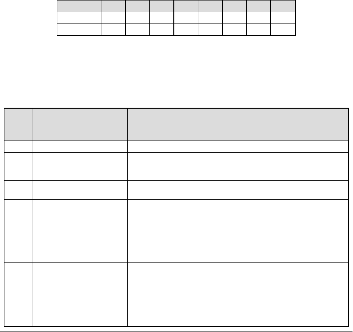
The communicator status codes will indicate the signal levels with digit 1 and 2, a network status with digit 3, and the trouble
status with digit 4 and 5 as indicated in table above. For example status code 11000F would display following status:
1 – On = Signal indicator 1, is ON
1 – On = Signal indicator 2, is ON
0 – OFF = Network indicator, network is working
00 – TROUBLE INDICATOR = there is no trouble on the communicator.
F – Future code not assigned yet. Itis sixth hexadecimal digit.It could be also ‘ - ‘ (dash) instead of letter F (11000-).
In this example both signal indicators are on indicating that communicator has excellent signal level; the network indicator is
OFF showing that we do not have any network problems and trouble indicators are both OFF indicating that we don’t have any
trouble on the communicator.
[985] Radio Initialization Status
The radio initialization status is intended to provide the installer with real-time status of radio communication. The radio ini-
tialization status is displayed in an 8 bit toggle option. Each digit indicates one task in the radio initialization process as follows:
1. Radio power up
2. Received the SMS from C24
3. Radio reset
4. Radio attached to network
5. Receiver 1 Initialized
6. Receiver 2 Initialized
7. Receiver 3 Initialized
8. Receiver 4 Initialize
The following table showseach digit position in the status code, each digit’s value and its assigned meaning in the eight-digit
code:
Table 16: Radio Initialization Status - 1-8 bits completion
Bit 12345678
Not Completed - - - - - - - -
Completed 1 2 3 4 5 6 7 8
For example, the radio initialization status code 12-45--- indicates that Radio has been powered up, it has received SMS signal
from C24, the radio is attached to the network, and Receiver 1 has been initialized. This code could be followed with...567 if
Receivers 2, 3, and 4 are initialized where applicable.
If the radio initialization status code does not indicate any problems,proceed with installation as per this manual. If troubles are
reported, reset the initialization process. If this action does not fix the problem,refer to Trouble shooting section in this manual.
Table 17: Trouble Code Indicators
Trouble
Indicator
Digit
Possible Causes Trouble Possible Solutions
00 No Trouble N/A
02 Panel Supervision Trouble
Check Section [382]Toggle Option[5] is ON (3G/Ethernet Module Enabled).
Ensure the PC- LINK cable between the Panel and Communicator is
connected properly (not reversed) and is securely in place.
04 Lockout Trouble The SIM card has incorrect PIN programmed or has a PIN that the module
does not recognize. Replace the SIM card.
05 3G/Cellular Trouble
Confirm that 3G service is available and active in your area.
Check all antenna connections.
Ensure average radio signal strength is CSQ 6 or higher. (See Table 7).
Ensure the SIM card is properly inserted into the SIM card holder.
Ensure the SIM card has been activated. (Could take up to 24 hrs after install).
If this trouble persists, relocate the Panel (and Communicator) or install an
external antenna extension kit.
06 Ethernet Trouble
Check with your ISP to confirm Internet service is active in your area.
Ensure your Ethernet cable is securely inserted into the RJ45 jack of the
Communicator and the Hub/Router/ Switch.
Check that the link light on the Hub/Router/ Switch is ON. If link light is OFF, try
restarting the Hub/Router/ Switch.
If DHCP is used, ensure that the unit has an assigned IP address from the
server.
27
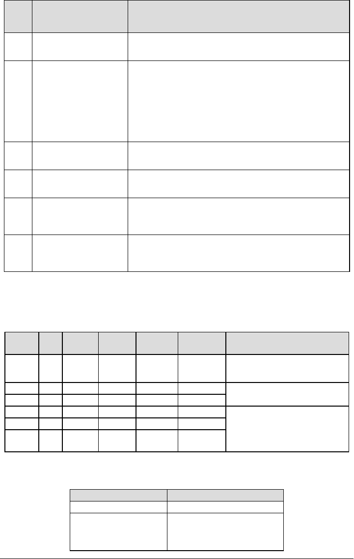
Trouble
Indicator
Digit
Possible Causes Trouble Possible Solutions
In Section [851] [992] verify a valid IP address is programmed. If not, contact
the Network administrator.
If problem persists, replace the Ethernet cable and RJ45 connector.
07 Receiver Not Available
Ensure that the Ethernet path has internet connectivity.
If you are using a static IP address make sure the gateway and subnet mask
are entered correctly.
If the network has a firewall, ensure the network has the programmed outgoing
ports open (Default UDP Port 3060 and Port 3065).
Ensure that all the receivers are programmed for DHCP or have the proper IP
address and port number.
Ensure the 3G Receiver APNs have been programmed with the Access Point
Name provided by your 3G provider.
08 Receiver Supervision Trouble
This trouble is indicated when supervision is enabled and the unit is not able to
successfully communicate with the receiver.
If this trouble persists, contact your central station.
09 FTC Trouble
The unit has exhausted all communications attempts to all programmed
receivers for events generated by the Communicator.
Restart the system. If trouble persists, contact your dealer.
0A Connect24 Configuration Failure
The SIM is active but there is no programming for the Communicator.
Ensure a profile has been programmed in Connect-24 for the SIM.
You can confirm your programming by calling the Connect- 24 VRU, or by
logging into the Connect24 VRU web site.
0C Module Configuration Trouble
This indication appears when Section [021] System Account Code, Section
[101], [111], [201], and [211] Receiver Account Code have not been
programmed. Ensure that a valid account code has been entered in these
Sections.
Communicator Troubleshooting
The status code for the radio signal strength, its typical troubles, possible causes and troubleshooting instructions is displayed
in the table below.
Table 18: Radio Signal Strength
Signal
Strength
CSQ
Level
Signal
Indicator 1
Signal
Indicator 2
Signal Level
[dBm]
Signal Level
Status Action Required
No Signal 0 0 0 -108.8 bad
Check all antenna connections.
Confirm 3G service is active in area.
Relocate Panel.
1 Bar 1 - 4 0 2 -108 ~ -103 weak Relocate Panel if signal strength shows
less than 3 bars.
2 Bars 5 - 6 0 1 -102 ~ -99 weak
3 Bars 7 - 10 2 1 -98 ~ -91 strong
Location is OK. 3G Signal Strength is
greater than CSQ 7.
4 Bars 11 - 13 2 1 -90 ~ -85 strong
5 Bars 14 + 1 1 -84 and
higher excellent
The table below displays the Network indicator codes and meaning of each code.
Table 19: Network indicator - Digit 3
Network indicator Value Means
OFF No Network Trouble
ON
Ethernet Cable disconnected
Ethernet DHCP failed
Radio connection has been rest
Radio IP failed
28

Network indicator Value Means
Flashing
Incoming transmission
Connect 24 programming
Outgoing transmission
Incoming transmission
29
Ethernet Cellular Programming
Worksheets
System Options
[001] Ethernet IP Address
Default (000.000.000.000)
[002] Ethernet IP Subnet Mask
Default (255.255.255.000)
[003] Ethernet Gateway IP Address
Default (000.000.000.000)
[004] Receiver Supervision Interval
Default (0087/135) Valid range: 0000 - FFFF.
[005] System Toggle Options
[1] Ethernet Receiver 1 Supervised Default (OFF).
[2] Cellular Receiver 1 Supervised Default (OFF).
[3] Supervision Type Default (OFF).
[4] Primary Communications Path.
Default [OFF] TL2553G(R)-E; [ON] 3G2055(R)-E.
[5] Redundant Communications Default (OFF).
[6] Remote Firmware Upgrade Default (ON).
[7] Alternate Test Transmission Default (OFF).
[8] Cellular Low Signal Trouble Default (OFF).
[006] System Toggle Options 2
[1] Ethernet Receiver 1 Enabled Default (ON).
[2] Ethernet Receiver 2 Enabled Default (ON).
[4] Cellular Receiver 1 Enabled Default (ON).
[5] Cellular Receiver 2 Enabled Default (ON).
[7] DLS Over Cellular Default (ON).
[8] Interactive Over Cellular Default (ON).
[007] DNS Server IP 1
Programming not permitted on UL/ULC listed system.
Default (000.000.000.000)
[008] DNS Server IP 2
Programming not permitted on UL/ULC listed system.
Default (000.000.000.000)
Programming Options
[010] System Toggle Options 3
[1] Enable 2-way audio over 3G
[011] Installer Code
Default (CAFE) Valid range: 0000 - FFFF.
[012] DLS Incoming Port
Default (0BF6/3062) Valid range: 0000 - FFFF.
[013] DLS Outgoing Port
Default (0BFA/3066) Valid range: 0000 - FFFF.
[020] Time Zone
Default (00) Valid range: 00 - 99.
[021] Account Code
Default (FFFFFF) Valid range: 000001 - FFFFFE.
[022] Communications Format
Default (04) Program 03 (CID), 04 (SIA).
[023] Panel Absent Trouble
Default (FF); Program 00 disable or FF enable.
[024] Panel Absent Trouble Restore
Default (FF) Program 00 disable or FF enable.
[025] Radio Activation Restore
Default (FF) Program 00 disable or FF enable.
System Test Options
[026] Ethernet 1 Transmission
Default (FF) Program 00 disable or FF enable.
[027] Ethernet 2 Transmission
Default (00) Program 00 disable or FF enable.
[028] Cellular 1 Transmission
Default (FF) Program 00 disable or FF enable.
[029] Cellular 2 Transmission
Default (00) Program 00 disable or FF enable.
[030] FTC Restore
Default (FF) Program 00 disable or FF enable.
[031] Priority Tamper Alarm
Default (FF) Program 00 disable or FF enable.
30

[032] Priority Tamper Restore
Default (FF) Program 00 disable or FF enable.
[033] Communicator Firmware Update Begin
Default (FF) Program 00 disable or FF enable.
[034] Communicator Firmware Update Suc-
cessful
Default (FF) Program 00 disable or FF enable.
[035] Panel Firmware Update Begin
Default (FF) Program 00 disable or FF enable.
[036] Panel Firmware Update Successful
Default (FF) Program 00 disable or FF enable.
[037] Panel Firmware Update Fail
Default (FF) Program 00 disable or FF enable.
Ethernet Receiver 1 Options
[101] Ethernet Receiver 1 Account Code
Default (0000000000)
Valid range: 0000000001 - FFFFFFFFFE.
[102] Ethernet Receiver 1 DNIS
Default (000000) Valid range: 000000 - FFFFFF.
[103] Ethernet Receiver 1 Address
Default (127.000.000.001)
[104] Ethernet Receiver 1 UDP Remote Port
Default (0BF5/3061) Valid range: 0000 - FFFF.
[105] Ethernet Receiver 1 UDP Local Port
Default (0BF4/3060)Valid range: 0000 - FFFF.
[106] Ethernet Receiver 1 Domain Name
Default ( ) 32 ASCII characters.
Programming not permitted on UL/ULC listed system.
________________________________
Ethernet Receiver 2 Options
[111] Ethernet Receiver 2 Account Code
Default (0000000000)
Valid range: 0000000001 - FFFFFFFFFE.
[112] Ethernet Receiver 2 DNIS
Default (000000) Valid range: 000000 - 0FFFFF.
[113] Ethernet Receiver 2 Address
Default (000.000.000.000)
[114] Ethernet Receiver 2 UDP Remote Port
Default (0BF5/3061) Valid range: 0000 - FFFF.
[115] Ethernet Receiver 2 UDP Local Port
Default (0BF9/3065) Valid range: 0000 -FFFF.
[116] Ethernet Receiver 2 Domain Name
Default ( )
Programming not permitted on UL/ULC listed system.
____________________________________
Ethernet Options
[124] Ethernet Test Transmission Time
Default (9999) Valid: 00-23(HH); 00-59(MM)
[125] Ethernet Test Transmission Cycle
Default (000000)
Valid range:000000 - 999999 minutes.
Cellular Receiver 1 Options
[201] Cellular Receiver 1 Account Code
Default (0000000000)
Valid range: 0000000001 - FFFFFFFFFE.
[202] Cellular Receiver 1 DNIS
Default (000000) Valid range: 000000 - 0FFFFF.
[203] Cellular Receiver 1 Address
Default (000.000.000.000). Valid range: 000-255.
[204] Cellular Receiver 1 Port
Default (0BF5/3061) Valid range: 0000 - FFFF.
[205] Cellular Receiver 1 APN Default ( )
32 ASCII characters.
____________________________________
[206] Cellular Receiver 1 Domain Name
Default ( )
32 Character ASCII characters.
____________________________________
Cellular Receiver 2 Options
[211] Cellular Receiver 2 Account Code
Default (0000000000)
Valid range: 0000000001 - FFFFFFFFFE.
31
[212] Cellular Receiver 2 DNIS
Default (000000)
Valid range: 000000 - 0FFFFF.
[213] Cellular Receiver 2 Address
Default (000.000.000.000)
Valid segment range: 000-255
[214] Cellular Receiver 2 Port
Default (0BF5/3061) Valid range: 0000 - FFFF.
[215] Cellular Receiver 2 APN
Default ( ) 32 ASCII characters.
____________________________________
[216] Cellular Receiver 2 Domain Name
Default ( ) 32 ASCII characters.
Programming not permitted on UL/ULC listed system.
____________________________________
Cellular Options
[221] Cellular Public Access Point Name
Default ( ) 32 ASCII characters
____________________________________
[222] Cellular Login User Name
Default ( ) 32 ASCII characters.
____________________________________
[223] Cellular Login Password
Default ( ) 32 ASCII characters.
____________________________________
[224] Cellular Test Transmission Time of Day
Default (9999) Valid range: 00 - 23 hrs. (HH) 00 - 59 min.
(MM).
[225] Cellular Test Transmission Cycle
Default (000000)
Valid range:000000 - 999999 minutes.
[226] Network Trouble Delay
Default (0F)
Valid entries from, 00 to FF.
Command and Control Options
[301] Command and Control Toggle Options
[1] Reserved
[2] Reserved
[3] SMS Command and Control Default (ON).
[4] Reserved
[5] SMS Character Format (OFF)
[6] Long SMS Message Handling Default (OFF).
[7] Reserved
[8] Reserved
[311]-[318] SMS Phone Number 1-8
This section may be programmed through DLS-IV or the
keypad.
______________________________________________
[321]-[328] SMS Phone Number 1-8 Toggle
Options
[1] SMS Notification Alarm/Restore Default (OFF).
[2] SMS Notification Tamper/Restore Default (OFF)
[3]SMSNotificationOpening/ClosingDefault(OFF).
[4] SMS Notification System Maintenance Default
(OFF)
[5] SMS Notification System Test Default (OFF)
[6] SMS Notification Internal Events Default (OFF).
[7] SMS Notification Enabled Default (OFF).
[8] SMS Command and Control Enabled Default
(ON).
[601] Stay Arm
Default (Stay Arm)
Send this command to the system to stay arm.
______________________________________________
[602] Away Arm
Default (Away Arm)
Send this command to the system to away arm.
______________________________________________
[603] Night Arm
Default (Night Arm)
Send this command to the system to night arm.
______________________________________________
[604] Disarm
Default (Disarm)
Send this command to the system to disarm.
______________________________________________
[605]-[608] Activate Command Output 1-4
Default (Activate Command Output n)
Send this command to the system to activate a command out-
put.
______________________________________________
[609]-[612] Deactivate Command Output 1-4
Default (Deactivate Command Output n)
Send this command to the system to deactivate a command
output.
______________________________________________
[613] Bypass
Default (Bypass)
Send this command to the system to bypass a zone.
______________________________________________
[614] Unbypass
Default (Unbypass)
Send this command to the system to unbypass a Zone.
32

______________________________________________
[615] Status Request
Default (Status Request)
Send this command to request the status of the system.
______________________________________________
[616] Alarm Memory Request
Default (Alarm Memory Request)
Send this command to request the alarm memory from the
system.
______________________________________________
[617] Help
Default (Help)
Access Code is not required.
______________________________________________
[619] Keypad Message
Default (Keypad Message)
[Account Label] _________________________________
[Date and Time] _________________________________
[SMS Function] _________________________________
[Response] ____________________________________
[Message Text]_________________________________
[621] Function Successful
Default (Successful)
Example: “stay armed successful.”
______________________________________________
[622] Function Failure
Default (Unsuccessful)
Example: “stay armed unsuccessful.”
______________________________________________
[623] Invalid Command
Default (Invalid Command)
Unprogrammable, enter correct command.
______________________________________________
[624] System Stay Armed
Default (Stay Armed)
Included in the response message if the command was not
accepted as a valid SMS command.
______________________________________________
[625] System Away Armed
Default (Away Armed)
Included in the response to a status request command if a par-
tition is away armed.
______________________________________________
[626] System Night Armed
Default (Night Armed)
Included in the response to a status request command if a par-
tition is night armed.
______________________________________________
[627] System Disarmed Ready
Default (Disarmed Ready)
Included in the response to a status request command if a par-
tition is disarmed and is ready to arm.
______________________________________________
[628] System Disarmed, Not Ready
Default (Disarmed Not Ready)
Included in the response to a status request command if a par-
tition is disarmed and is not ready to arm.
______________________________________________
[629] System In Alarm
Default (is in Alarm)
This label will be included in the response to an Alarm
Memory Request if there are no alarms on the system
______________________________________________
[630] Trouble Label
Default (Service is Required)
Included in the response to the Alarm Memory command if
there are no alarms in memory.
______________________________________________
[631] No Alarms in Memory
Default (No Alarms in Memory)
Included in the response to the Alarm Memory command if
there are no alarms on the system.
______________________________________________
[634] Response Code
Default (Response Code)
Included in the response to an Alarm Memory Request if
there are no alarms on the system
______________________________________________
Receiver Diagnostic Testing
[901] Diagnostic Test Transmission
[1] Ethernet 1 Default (OFF).
[2] Ethernet 2 Default (OFF).
[3] Cellular 1 Default (OFF).
[4] Cellular 2 Default (OFF).
System Information (Read Only)
[988] DNS 1 IP Address
[989] DNS 2 IP Address
[991] Firmware Version
[992] Ethernet IP Address
[993] Ethernet Gateway Address
[994] Cellular IP Address
[995] SIM Number
____________________________________
[996] Cellular Telephone Number
This number is required for DLS and Firmware upgrades.
____________________________________
[997] IMEI Number
____________________________________
33

[998] MAC Address
System Reset Defaults
[999] Software Default
Default (99); Valid entries are 00 or 55
EULA
IMPORTANT - READ CAREFULLY: DSC Software purchased with or without
Productsand Componentsis copyrighted and ispurchased under the following
license terms:
ThisEnd- UserLicense Agreement (“EULA”) isa legal agreement between You
(the company, individual or entity who acquired the Software and any related
Hardware) and Digital Security Controls, a division of Tyco Safety Products
Canada Ltd. (“DSC”), the manufacturer of the integrated security systems and
the developer of the software and any related products or components
(“HARDWARE”)which You acquired.
If the DSC software product (“SOFTWAREPRODUCT” or“SOFTWARE”)is inten-
ded to be accompanied by HARDWARE, and is NOT accompanied by new
HARDWARE, You may not use, copy orinstall the SOFTWARE PRODUCT. The
SOFTWARE PRODUCT includes computer software, and may include asso-
ciated media, printed materials, and “online” orelectronic documentation.
Anysoftware provided along with the SOFTWAREPRODUCT that is associated
with a separate end-user license agreement islicensed to You underthe terms of
that license agreement.
By installing, copying, downloading, storing, accessing or otherwise using the
SOFTWAREPRODUCT, You agree unconditionallyto be bound by the terms of
this EULA, even if this EULA is deemed to be a modification of any previous
arrangement or contract. If You do not agree to the terms of thisEULA, DSC is
unwilling to license the SOFTWAREPRODUCT to You, and You have no right to
use it.
SOFTWARE PRODUCT LICENSE
The SOFTWARE PRODUCT is protected by copyright laws and international
copyright treaties, as well as other intellectual property laws and treaties. The
SOFTWAREPRODUCT islicensed, not sold.
1. GRANT OF LICENSE This EULA grants You the following rights:
Software Installation and Use -For each license You acquire, You may have
onlyone copyof the SOFTWAREPRODUCT installed.
Storage/Network Use - The SOFTWARE PRODUCT may not be installed,
accessed, displayed, run, shared or used concurrentlyon or from different com-
puters, including a workstation, terminal or other digital electronic device
(“Device”). In other words, if You have several workstations, You will have to
acquire a license foreach workstation where the SOFTWAREwillbe used.
Backup Copy - You maymake back-up copies of the SOFTWARE PRODUCT,
but You may onlyhave one copyper license installed at anygiven time. You may
use the back-up copysolelyfor archivalpurposes. Except asexpressly provided in
thisEULA, You maynot otherwise make copiesof the SOFTWARE PRODUCT,
including the printed materialsaccompanying the SOFTWARE.
2. DESCRIPTION OFOTHER RIGHTSAND LIMITATIONS
Limitations on Reverse Engineering, Decompilation and Disassembly -
You may not reverse engineer, decompile, or disassemble the SOFTWARE
PRODUCT, except and only to the extent that such activityisexpressly permitted
byapplicable law notwithstanding thislimitation. You may not make any changes
ormodifications to the Software, without the written permission of an officer of
DSC. You may not remove any proprietarynotices, marksor labels fromthe Soft-
ware Product. You shallinstitute reasonable measuresto ensure compliance with
the termsand conditionsof thisEULA.
Separation of Components - The SOFTWARE PRODUCT is licensed as a
single product. Its component parts may not be separated for use on more than
one HARDWAREunit.
Single INTEGRATED PRODUCT - If You acquired this SOFTWARE with
HARDWARE, then the SOFTWAREPRODUCT is licensed with the HARDWARE
asa single integrated product. In thiscase, the SOFTWAREPRODUCT may only
be used with the HARDWAREasset forth in thisEULA.
Rental - You may not rent, lease orlend the SOFTWAREPRODUCT. You may
not make it available to othersorpostit on a serveror web site.
Software Product Transfer -You maytransfer allof Your rights under this EULA
onlyas part of a permanent sale or transfer of the HARDWARE, provided You
retain no copies, You transferallof the SOFTWAREPRODUCT (including all com-
ponent parts, the media and printed materials, any upgrades and this EULA),
and provided the recipient agrees to the terms of this EULA. If the SOFTWARE
PRODUCT is an upgrade, anytransfer must also include all priorversions of the
SOFTWAREPRODUCT.
Termination - Without prejudice to any other rights, DSC may terminate this
EULA if You fail to comply with the terms and conditions of this EULA. In such
event, You must destroy allcopies of the SOFTWAREPRODUCT and all of its com-
ponentparts.
Trademarks - ThisEULA doesnot grant You anyrights in connection with any
trademarks or service marksof DSC oritssuppliers.
3. COPYRIGHT
Alltitle and intellectualpropertyrightsin and to the SOFTWAREPRODUCT (includ-
ing but not limited to any images, photographs, and text incorporated into the
SOFTWAREPRODUCT), the accompanying printed materials,and anycopies of
the SOFTWARE PRODUCT, are owned by DSC or its suppliers. You may not
copythe printed materialsaccompanying the SOFTWAREPRODUCT. Alltitle and
intellectualpropertyrights in and to the content which maybe accessed through
use of the SOFTWARE PRODUCT are the property of the respective content
owner and maybe protected byapplicable copyright orotherintellectualproperty
lawsand treaties. This EULAgrants You no rights to use such content. All rights
not expresslygranted under thisEULAare reserved byDSC and itssuppliers.
EXPORT RESTRICTIONS- You agree that You will not export orre-export the
SOFTWARE PRODUCT to any country, person, or entity subject to Canadian
export restrictions.
CHOICEOFLAW - This Software License Agreement isgoverned by the laws of
the Province of Ontario, Canada.
ARBITRATION - All disputes arising in connection with this Agreement shall be
determined byfinaland binding arbitration in accordance with the Arbitration Act,
and the partiesagree to be bound bythe arbitrator’sdecision. The place of arbit-
ration shall be Toronto, Canada, and the language of the arbitration shall be
English.
LIMITED WARRANTY
NO WARRANTY - DSC PROVIDES THE SOFTWARE “AS IS” WITHOUT
WARRANTY. DSC DOES NOT WARRANT THAT THE SOFTWARE WILL MEET
YOUR REQUIREMENTS OR THAT OPERATION OF THESOFTWARE WILL BE
UNINTERRUPTED OR ERROR-FREE.
CHANGES IN OPERATING ENVIRONMENT - DSC shallnot be responsible for
problemscaused bychangesin the operating characteristicsof the HARDWARE,
orfor problems in the interaction of the SOFTWARE PRODUCT with non- DSC-
SOFTWAREorHARDWAREPRODUCTS.
LIMITATION OF LIABILITY; WARRANTY REFLECTS ALLOCATION OF
RISK - IN ANY EVENT, IF ANY STATUTE IMPLIES WARRANTIES OR
CONDITIONS NOT STATED IN THIS LICENSE AGREEMENT, DSC’S ENTIRE
LIABILITYUNDER ANYPROVISION OF THISLICENSEAGREEMENT SHALL BE
LIMITED TO THE GREATER OF THE AMOUNT ACTUALLY PAID BY YOU TO
LICENSE THE SOFTWARE PRODUCT AND FIVE CANADIAN DOLLARS
(CAD$5.00). BECAUSE SOME JURISDICTIONS DO NOT ALLOW THE
EXCLUSION OR LIMITATION OF LIABILITY FOR CONSEQUENTIAL OR
INCIDENTAL DAMAGES, THE ABOVELIMITATION MAY NOT APPLYTO YOU.
DISCLAIMER OF WARRANTIES - THISWARRANTYCONTAINSTHE ENTIRE
WARRANTYAND SHALL BEIN LIEU OFANYAND ALL OTHER WARRANTIES,
WHETHER EXPRESSED OR IMPLIED (INCLUDING ALL IMPLIED
WARRANTIES OF MERCHANTABILITY OR FITNESS FOR A PARTICULAR
PURPOSE)AND OFALL OTHER OBLIGATIONSOR LIABILITIESON THE PART
OF DSC. DSC MAKES NO OTHER WARRANTIES. DSC NEITHER ASSUMES
NOR AUTHORIZES ANY OTHER PERSON PURPORTING TO ACT ON ITS
BEHALFTO MOD8IFY OR TO CHANGE THIS WARRANTY, NOR TO ASSUME
FOR IT ANY OTHER WARRANTY OR LIABILITY CONCERNING THIS
SOFTWAREPRODUCT.
EXCLUSIVE REMEDY AND LIMITATION OF WARRANTY - UNDER NO
CIRCUMSTANCESSHALL DSC BE LIABLE FOR ANY SPECIAL, INCIDENTAL,
CONSEQUENTIAL OR INDIRECT DAMAGES BASED UPON BREACH OF
WARRANTY, BREACH OF CONTRACT, NEGLIGENCE, STRICT LIABILITY, OR
ANY OTHER LEGAL THEORY. SUCH DAMAGES INCLUDE, BUT ARE NOT
LIMITED TO, LOSS OF PROFITS, LOSS OF THE SOFTWARE PRODUCT OR
ANY ASSOCIATED EQUIPMENT, COST OF CAPITAL, COST OF SUBSTITUTE
OR REPLACEMENT EQUIPMENT, FACILITIES OR SERVICES, DOWN TIME,
PURCHASERS TIME, THE CLAIMS OF THIRD PARTIES, INCLUDING
CUSTOMERS, AND INJURYTO PROPERTY.
DSC recommends that the entire system be completelytested on a regular basis.
However, despite frequent testing, and due to, but not limited to, criminal tam-
pering or electricaldisruption, it ispossible for thisSOFTWAREPRODUCT to fail to
performasexpected.
DigitalSecurityControlswarrantsthe originalpurchaserthat fora period of twelve
monthsfromthe date of purchase, the productshallbe free of defectsin mater-
ials and workmanship under normal use. During the warranty period, Digital
Security Controlsshall, at itsoption, repairor replace anydefective product upon
return of the product to its factory, at no charge for labour and materials. Any
replacement and/or repaired parts are warranted for the remainder of the ori-
ginal warranty or ninety (90) days, whichever is longer. The original purchaser
must promptlynotifyDigitalSecurityControlsin writing that there is defect in mater-
ialor workmanship, such written notice to be received in all eventsprior to expir-
ation of the warranty period. There is absolutelyno warranty on software and all
software products are sold as a user license under the terms of the software
license agreement included with the product. The Customerassumesall
Limited Warranty
34
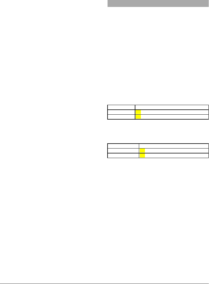
responsibility forthe properselection, installation, operation and maintenance of
anyproducts purchased from DSC. Custom productsare onlywarranted to the
extent that theydo not function upon delivery.In such cases, DSC can replace or
credit at its option.
International Warranty
The warranty for internationalcustomers is the same as forany customer within
Canada and the United States, with the exception that DigitalSecurity Controls
shallnot be responsible for anycustomsfees, taxes, orVAT that may be due.
Warranty Procedure
To obtain service underthis warranty, please return the item(s)in question to the
point of purchase. All authorized distributors and dealers have a warranty pro-
gram. Anyone returning goods to Digital Security Controls must first obtain an
authorization number. DigitalSecurity Controlswillnot accept anyshipment what-
soeverforwhich priorauthorization hasnot been obtained.
Conditions to Void Warranty
Thiswarrantyappliesonly to defectsin parts and workmanship relating to normal
use. It doesnot cover:
ldamage incurred in shipping orhandling;
ldamage caused bydisastersuch asfire, flood, wind, earthquake or light-
ning;
ldamage due to causes beyond the controlof DigitalSecurityControlssuch
asexcessive voltage, mechanicalshockor water damage;
ldamage caused byunauthorized attachment, alterations, modificationsor
foreign objects;
ldamage caused byperipherals(unlesssuch peripheralswere supplied by
DigitalSecurityControls);
ldefectscaused byfailure to provide a suitable installation environment for
the products;
ldamage caused byuse of the productsforpurposesotherthan those for
which it wasdesigned;
ldamage fromimpropermaintenance;
ldamage arising out of anyotherabuse, mishandling or improperapplication
of the products.
Items Not Covered by Warranty
In addition to the itemswhich void the Warranty, the following itemsshall not be
covered byWarranty:(i) freight costto the repaircentre; (ii)productswhich are not
identified with DSC'sproduct labeland lot number orserial number; (iii) products
disassembled orrepaired in such a manner asto adverselyaffectperformance or
prevent adequate inspection or testing to verifyany warrantyclaim.Access cards
ortags returned for replacement under warranty will be credited or replaced at
DSC'soption. Productsnot covered bythiswarranty, or otherwise out of warranty
due to age, misuse, ordamage shall be evaluated, and a repairestimate shall be
provided. No repairworkwill be performed untila valid purchase orderis received
from the Customer and a Return Merchandise Authorisation number (RMA) is
issued byDSC'sCustomerService.
DigitalSecurity Controls’s liability for failure to repair the product under this war-
rantyaftera reasonable numberof attemptswillbe limited to a replacement of the
product, asthe exclusive remedyfor breach of warranty. Under no circumstances
shallDigitalSecurity Controlsbe liable for anyspecial, incidental, or consequential
damages based upon breach of warranty, breach of contract, negligence, strict
liability,or any other legaltheory. Such damages include, but are not limited to,
lossof profits, loss of the product or any associated equipment, cost of capital,
cost of substitute or replacement equipment, facilitiesor services, down time, pur-
chaser’stime, the claimsof third parties, including customers, and injury to prop-
erty. The laws of some jurisdictions limit or do not allow the disclaimer of
consequentialdamages. If the laws of such a jurisdiction apply to any claimby or
against DSC, the limitations and disclaimers contained here shall be to the
greatest extent permitted bylaw. Some statesdo not allow the exclusion or lim-
itation of incidental orconsequential damages,so that the above maynot apply
to you.
Disclaimer of Warranties
This warranty contains the entire warranty and shall be in lieu of any
and all other warranties, whether expressed or implied (including all
implied warranties of merchantability or fitness for a particular pur-
pose) And of all other obligations or liabilities on the part of Digital
Security Controls Digital Security Controls neither assumes respons-
ibility for, nor authorizes any other person purporting to act on its
behalf to modify or to change this warranty, nor to assume for it any
other warranty or liability concerning this product.
This disclaimer of warranties and limited warranty are governed by the
laws of the province of Ontario, Canada.
DigitalSecurityControlsrecommendsthat the entire systembe completely tested
on a regularbasis. However, despite frequent testing, and due to, but not limited
to, criminaltampering orelectrical disruption, it ispossible for thisproduct to fail to
performasexpected.
Installer’s Lockout
Anyproductsreturned to DSCwhich have the Installer’s Lockout option enabled
and exhibit no other problemswillbe subjectto a service charge.
Out of Warranty Repairs
DigitalSecurityControlswillat itsoption repairorreplace out-of-warrantyproducts
which are returned to its factory according to the following conditions. Anyone
returning goodsto DigitalSecurityControlsmust firstobtain an authorization num-
ber. Digital Security Controlswill not accept anyshipment whatsoever for which
prior authorization hasnot been obtained.
Products which Digital Security Controls determines to be repairable will be
repaired and returned. A set fee which Digital Security Controls has pre-
determined and which maybe revised from time to time, willbe charged for each
unitrepaired.
Productswhich Digital Security Controls determines not to be repairable will be
replaced by the nearest equivalent product available at that time. The current
market price of the replacement product will be charged for each replacement
unit.
Regulatory Information
MODIFICATION STATEMENT
DigitalSecurity Controls has not approved any changes or modifications to this
device bythe user.Any changesormodificationscould void the user’s authority to
operate the equipment.
Digital Security Controls n’approuve aucune modification apportée à l’appareil
par l’utilisateur, quelle qu’en soit la nature. Tout changement ou modification
peuvent annulerle droit d’utilisation de l’appareilparl’utilisateur.
INTERFERENCE STATEMENT
Thisdevice complieswith Part 15 of the FCC Rulesand IndustryCanada licence-
exempt RSSstandard(s). Operation is subject to the following two conditions: (1)
thisdevice maynot cause interference, and (2)thisdevice must accept any inter-
ference, including interference that may cause undesired operation of the
device.
Le présent appareilest conforme aux CNR d'Industrie Canada applicables aux
appareils radio exempts de licence. L'exploitation est autorisée aux deux con-
ditions suivantes : (1) l'appareil ne doit pas produire de brouillage, et (2) l'util-
isateurde l'appareil doit accepter tout brouillage radioélectrique subi, même si le
brouillage est susceptible d'en compromettre le fonctionnement.
WIRELESS NOTICE
Thisequipment complieswith FCC and IC radiation exposure limitsset forth foran
uncontrolled environment. The antenna should be installed and operated with
minimumdistance of 20 cmbetween the radiator and yourbody.
Antenna gain mustbe below:
Frequency Band TL255GR-E, TL25535-E, 3G2055R-E, 3G2055-E
GSM850 / FDD V 6.69 dBi
PCS 1900 / FDD II 9.31 dBi
Thistransmittermust not be co-located or operating in conjunction with any other
antenna or transmitter.
Cet appareil est conforme aux limites d'exposition aux rayonnements de la IC
pour un environnement non contrôlé. L'antenne doit être installé de façon à
garder une distance minimale de 20 centimètres entre la source de ray-
onnementset votre corps. Gain de l'antenne doit être ci-dessous:
Bande de fréquence TL255GR-E, TL25535-E, 3G2055R-E, 3G2055-E
GSM 850 / FDD V 6.69 dBi
PCS 1900 / FDD II 9.31 dBi
L'émetteurne doit pasêtre colocalisé ni fonctionnerconjointement avecà autre
antenne ou autre émetteur.
FCC CLASS B DIGITAL DEVICE NOTICE
Thisequipment has been tested and found to comply with the limits for a Class B
digitaldevice, pursuant to part 15 of the FCC Rules. These limitsare designed to
provide reasonable protection against harmfulinterference in a residential install-
ation. This equipment generatesuses and canradiate radio frequency energy
and, if not installed and used in accordance with the instructions,maycause harm-
fulinterference to radio communications. However, there is no guarantee that
interference willnot occur in a particular installation. If thisequipment does cause
harmfulinterference to radio ortelevision reception, which can be determined by
turning the equipment off and on, the user is encouraged to try to correct the
interference byone ormore of the following measures:
•Reorient or relocate the receiving antenna.
•Increase the separation between the equipment and receiver.
•Connect the equipment into an outlet on a circuit different fromthat to which the
receiverisconnected.
•Consultthe dealeroran experienced radio/TVtechnician for help
CAN ICES-3 (B)/ NMB-3 (B)
FCC ID:F5315TL2553GRE
Industry Canada Compliance Statement
ThisEquipment meetsthe applicable IndustryCanada TerminalEquipment Tech-
nical Specifications. This is confirmed by the registration number. The abbre-
viation, IC, before the registration number signifies that registration was
performed based on a Declaration of Conformityindicating that IndustryCanada
technical specifications were met. It does not imply that that Industry Canada
approved the equipment. The Ringer Equivalence Number (REN) for this ter-
minalequipment is 0.0. The REN assigned to each terminalequipment provides
an indication of the maximumnumber of terminals allowed to be connected to a
telephone interface. The termination on an interface may consist of any
35

combination of devices subject onlyto the requirement that the sumof the Ringer
Equivalence Numbersof alldevicesdoes not exceed 5.
IC:160A-TL2553GRE
Cet équipement est conforme aux spécifications techniques applicables aux
équipements terminaux d'Industrie Canada. Ceci est confirmé par le numéro
d'enregistrement. L'abréviation IC précédant le numéro d'enregistrement signifie
que l'enregistrement a été effectué sur la base de la Déclaration de conformité
indiquant que le produit estconforme aux spécifications techniques d'Industrie
Canada. Ceci n'implique pas que le produit ait été approuvé par Industrie
Canada.
Le nombre équivalent de sonneries (REN) de cet appareil terminal est 0.0. Le
REN attribué à chaque équipement terminalfournit une indication sur le nombre
maximumde terminaux pouvant être connectés surune interface téléphonique.
La terminaison sur une interface peut constitueren n'importe quelle combinaison
d'appareils,à la condition seulement que la somme desNombreséquivalents de
sonneriesde touslesappareilsne soit passupérieure à 5.
This Class B digital apparatus meets all requirements of the Canadian inter-
ference-causing equipment regulations. Cet appareilnumérique de la Classe B
respecte touteslesexigencesde règlement surle matérielbrouilleurdu Canada.
The term “IC:” before the radio certification number only signifies that Industry
Canada technicalspecificationswere met.
NIST Validation of encryption algorithmAES128 certificate No. 3161
36

© 2015 Tyco Security Products. All Rights Reserved.
Tech Support: 1-800-387-3630 (Canada & U.S.) or 905-760-3000
www.dsc.com
The trademarks,logos, and service marksdisplayed on thisdocument are registered in the United States[or othercountries]. Anymisuse of the trademarksis strictly pro-
hibited and Tyco willaggressively enforce its intellectualproperty rightsto the fullest extent of the law, including pursuitof criminalprosecution wherevernecessary. All
trademarksnot owned byTyco are the propertyof their respective owners, and are used with permission or allowed underapplicable laws.
Product offeringsand specificationsare subject to change without notice. Actualproductsmay varyfromphotos. Not allproductsinclude allfeatures. Availabilityvaries by
region; contact your sales representative.
5
37

38