UAB Teltonika Networks RUT950 RUT950 User Manual
UAB Teltonika RUT950
UserManual.wiki
>
UAB Teltonika Networks
>
RUT950 User Manual
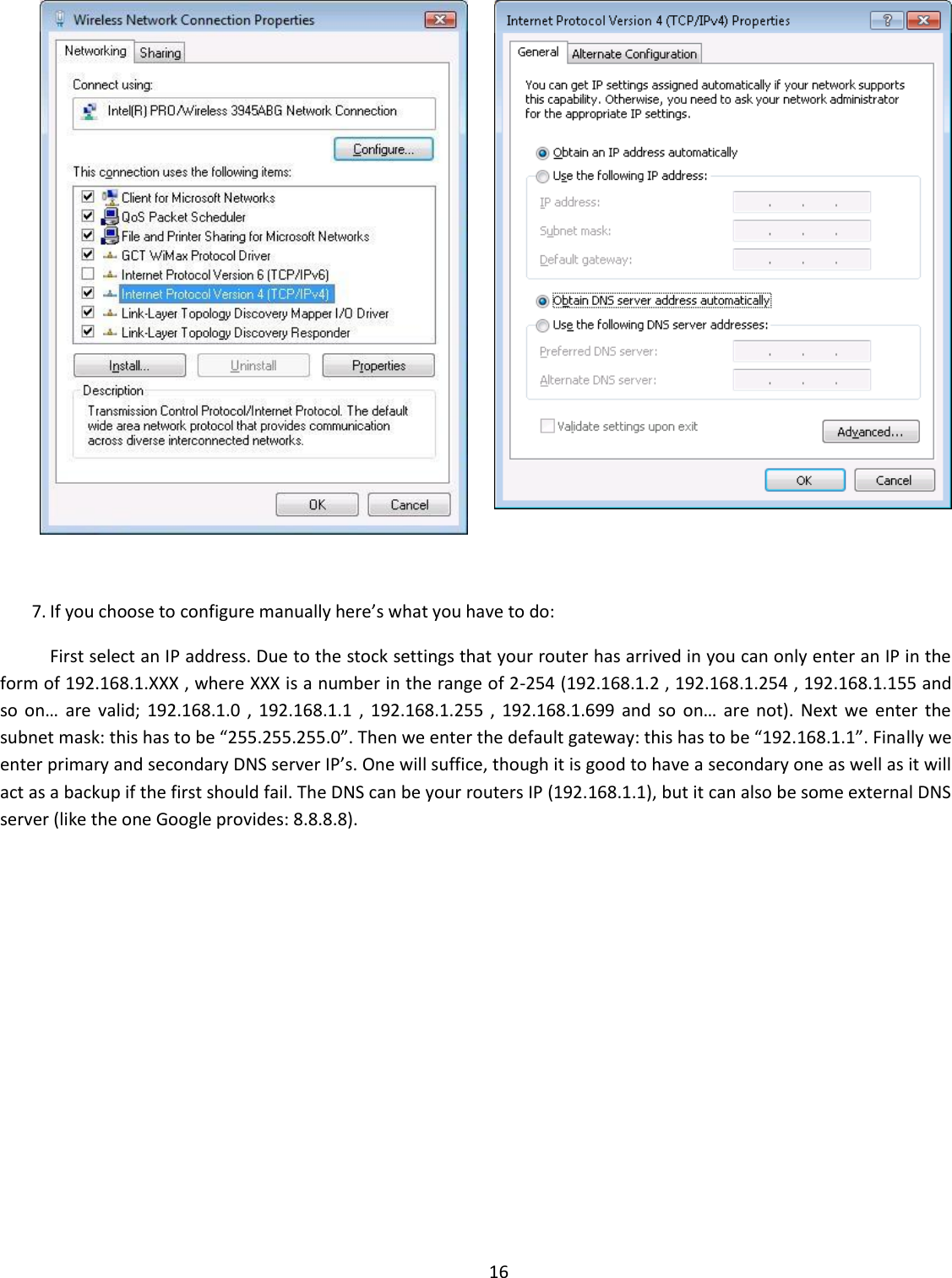
>
Users Manual-1
Contents
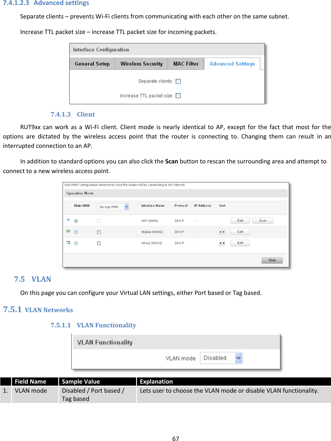
1.
Users Manual-1
2.
Users Manual-2
Users Manual-1
Navigation menu
Upload a User Manual
Namespaces
Wiki Guide
HTML
PDF
Info
Views
User Manual
Discussion / Help
Navigation
![1 USER MANUAL RUT950 LTE Router [Type a quote from the document or the summary of an interesting point. You can position the text box anywhere in the document. Use the Drawing Tools tab to change the formatting of the pull quote text box.]](https://usermanual.wiki/UAB-Teltonika-Networks/RUT950.Users-Manual-1/User-Guide-3550903-Page-1.png)
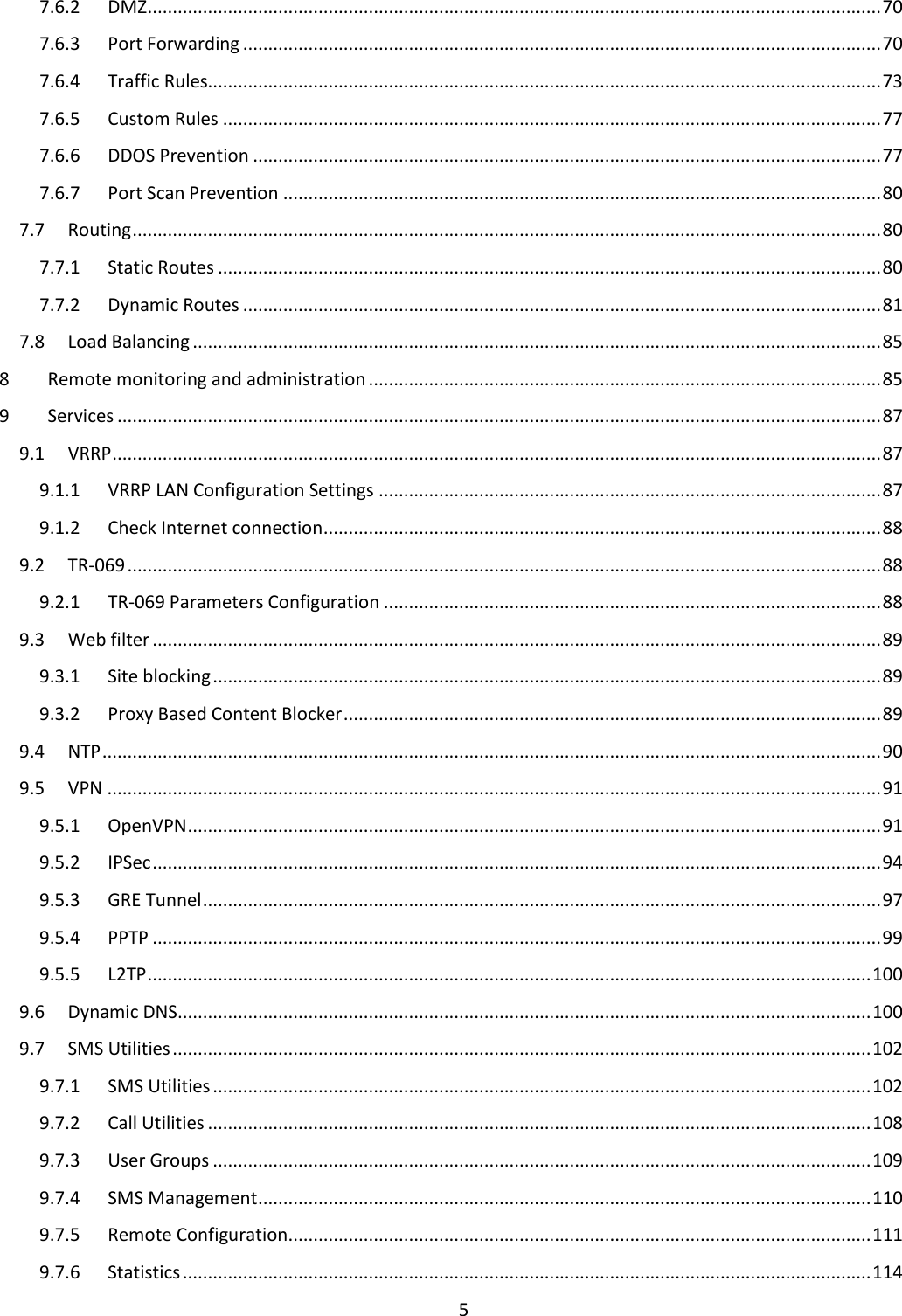
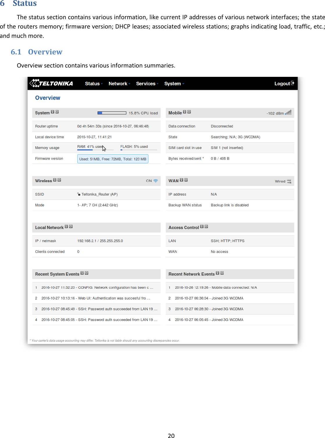
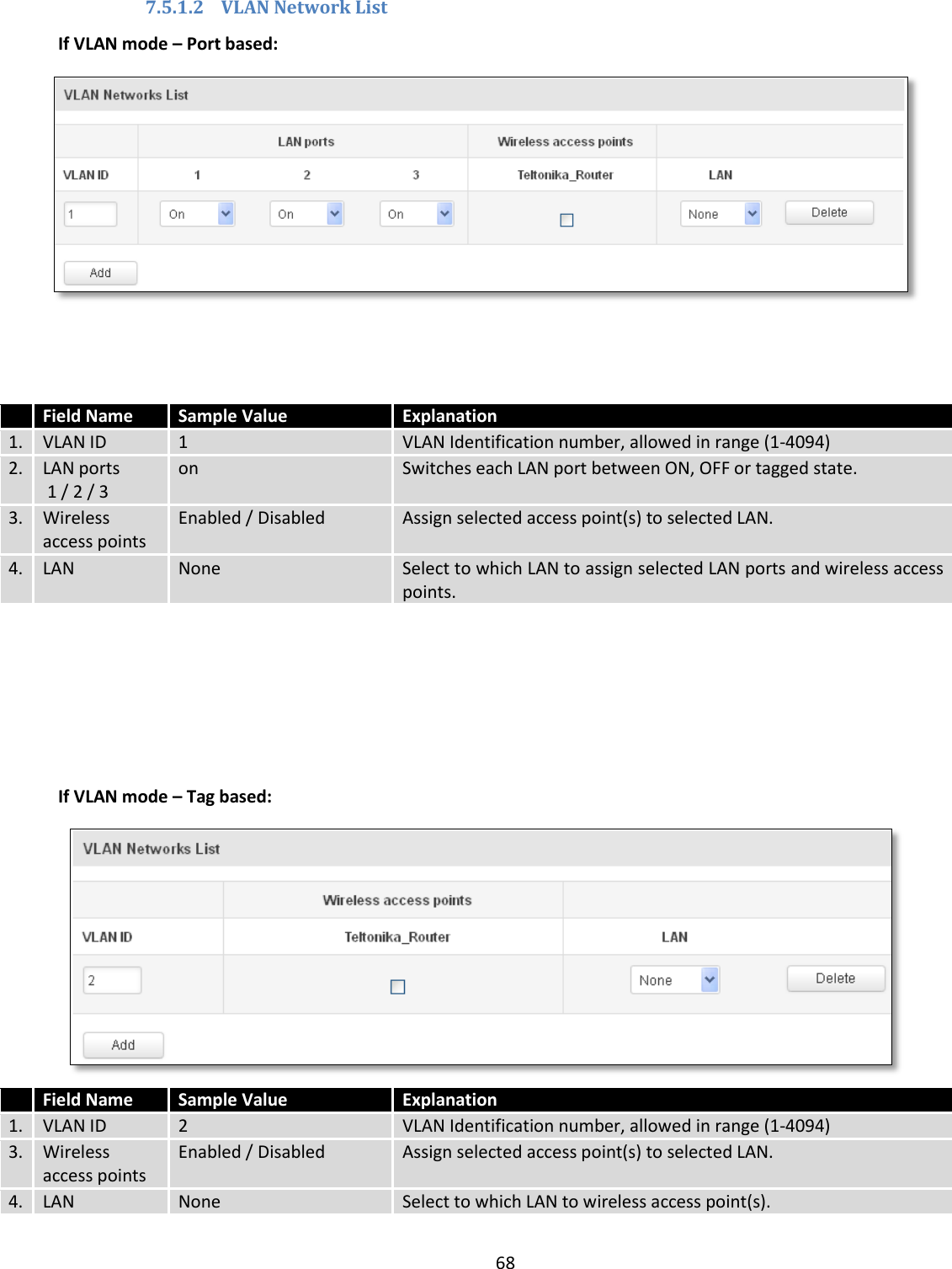
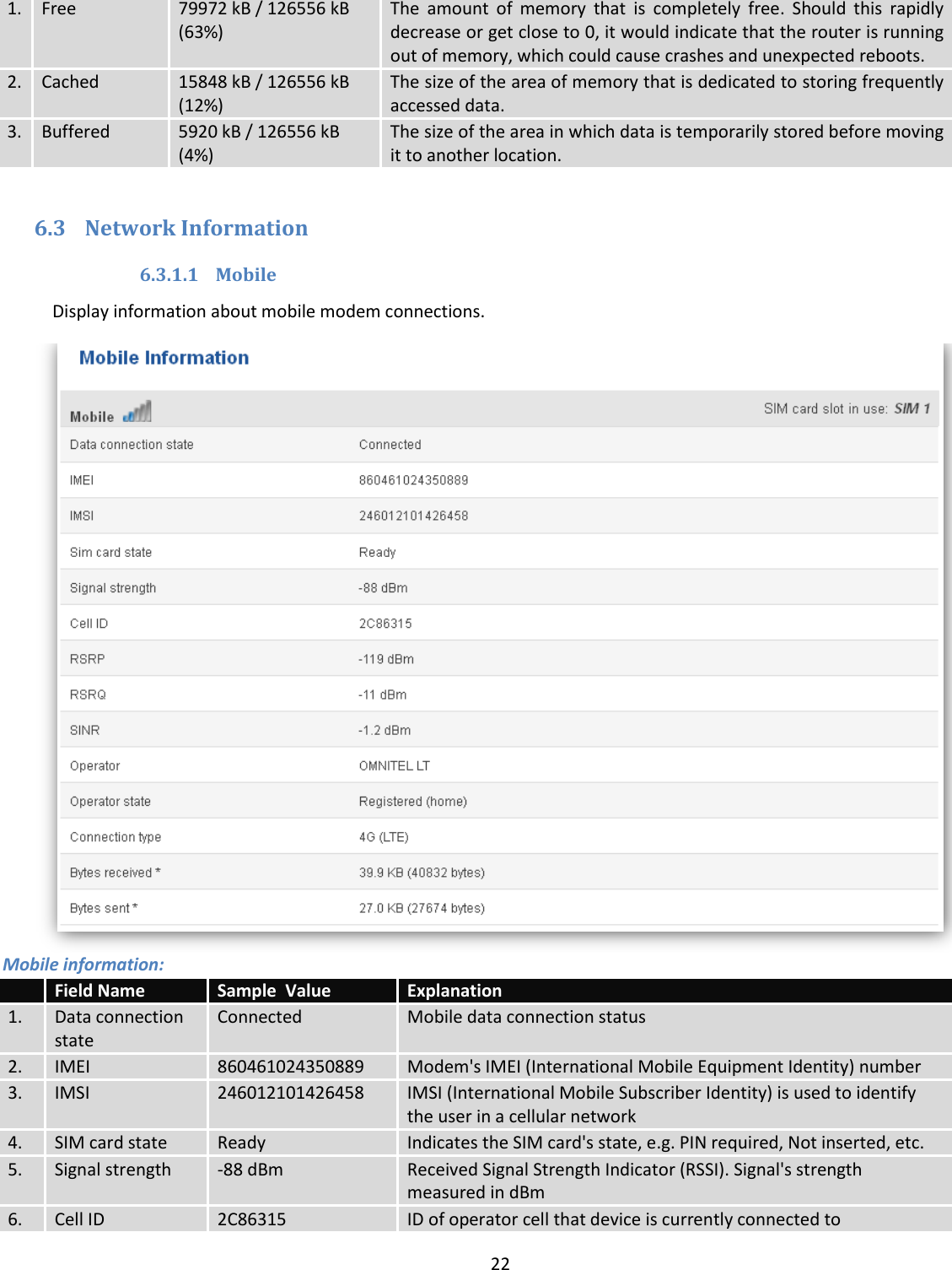
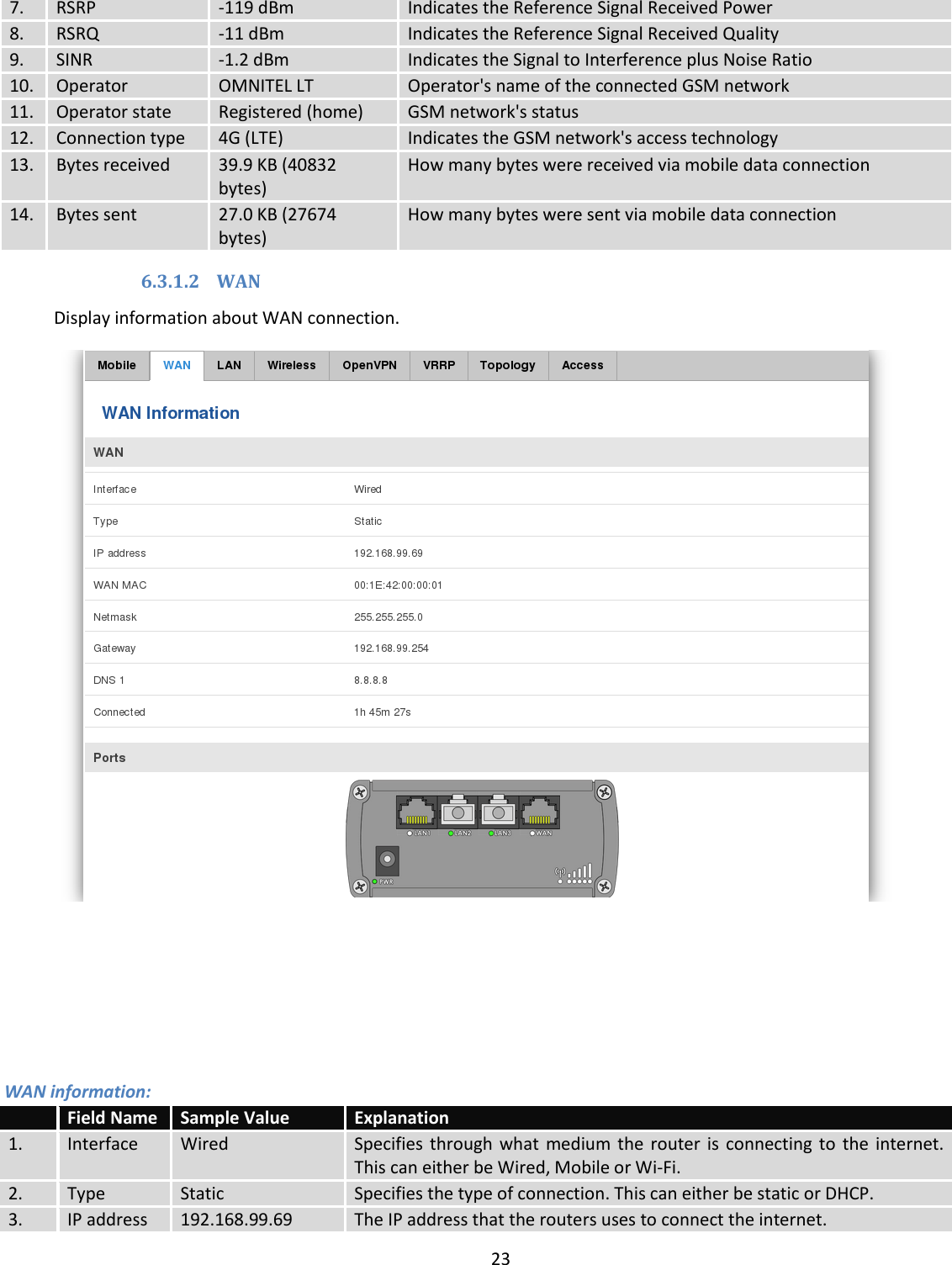
![21 6.2 System Information The System Information tab contains data that pertains to the routers operating system. System explanation: Field Name Sample value Explanation 1. Router Name RUT950 Name of the router (hostname of the routers system). Can be changed in System -> Administration. 2. Host name Teltonika-RUT950.com Indicates how router will be seen by other devices on the network. Can be changed in System -> Administration. 3. Router Model Teltonika RUT950 LTE Routers model. 4. Firmware Version RUT9XX_R_00.02.345 Shows the version of the firmware that is currently loaded in the router. Newer versions might become available as new features are added. Use this field to decide whether you need a firmware upgrade or not. 5. Kernel Version 3.10.36 The version of the Linux kernel that is currently running on the router. 6. Local Time 2016-05-06, 05:54:10 Shows the current system time. Might differ from your computer, because the router synchronizes it's time with an NTP server. Format [year-month-day, hours: minutes: seconds]. 7. Uptime 0d 0h 47m 35s (since 2016-05-06, 05:06:35) Indicates how long it has been since the router booted up. Reboots will reset this timer to 0. Format *day’s hours minutes seconds (since year-month-day, hours: minutes: seconds)]. 8. Load Average 1 min: 100%; 5 mins: 87%; 15 mins: 52% Indicates how busy the router is. Let's examine some sample output: "1 min: 22%, 5 mins: 13%, 15 mins: 20%". The first number mean past minute and second number 22% means that in the past minute there have been, on average, 22% processes running or waiting for a resource. 9. Temperature 34° C Device’s temperature Memory explanation: Field Name Sample Value Explanation](https://usermanual.wiki/UAB-Teltonika-Networks/RUT950.Users-Manual-1/User-Guide-3550903-Page-21.png)

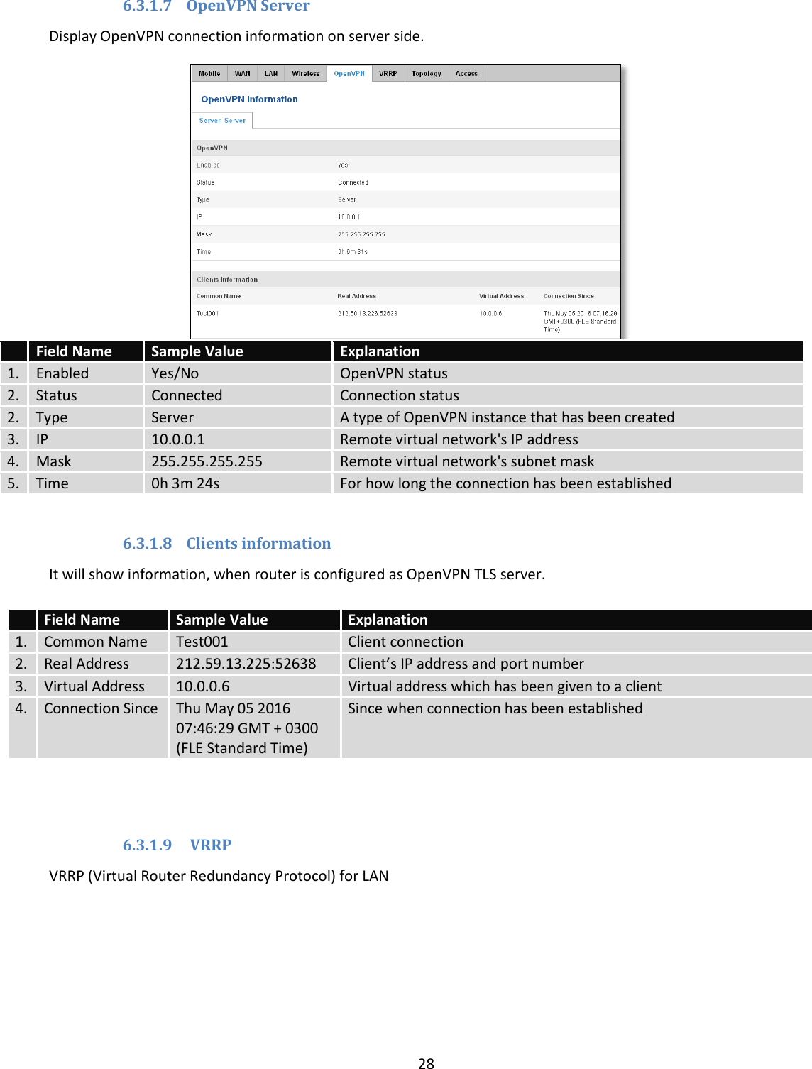
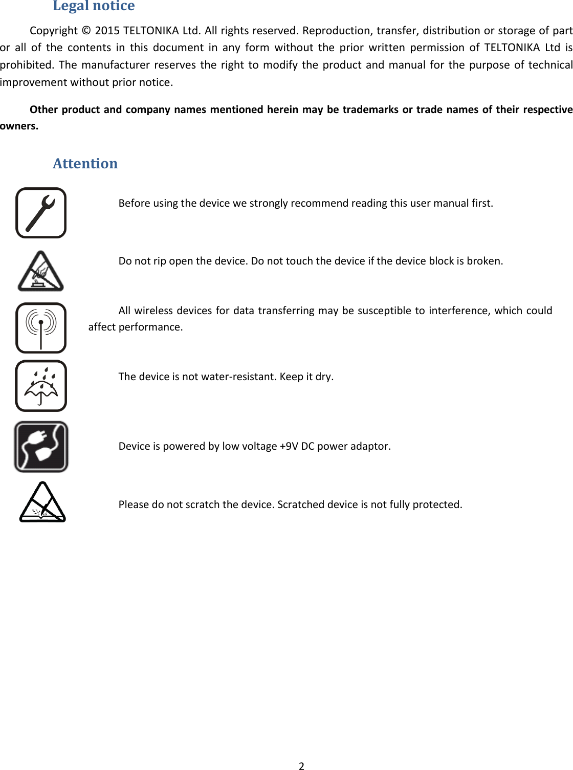
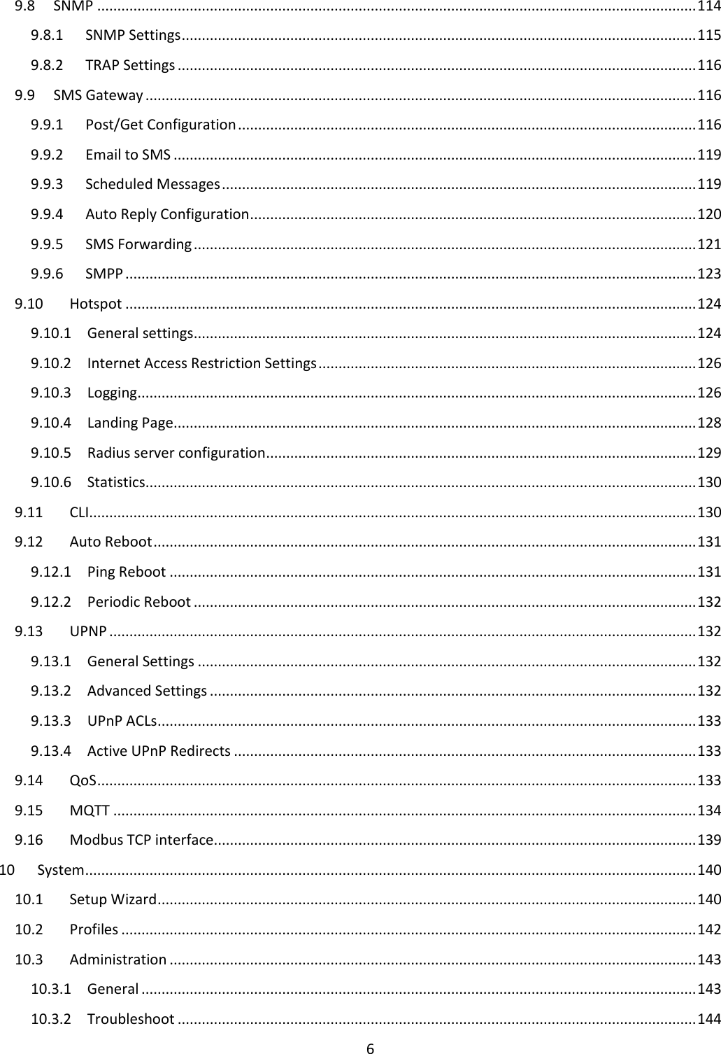
![29 Field Name Sample Value Explanation 1. Status Enabled VRRP status 2. Virtual IP 192.168.1.253 Virtual IP address(- es) for LAN’s VRRP (Virtual Router Redundancy Protocol ) cluster 3. Priority 100 Router with highest priority value on the same VRRP (Virtual Router Redundancy Protocol) cluster will act as a master, range [1 - 255] 4. Router** Master Connection mode – Master **-Exclusive to other Modes with Slave. 6.3.1.10 Topology Network scanner allows you to quickly retrieve information about network devices. When router is configured to use Mobile as WAN and Connection type is selected „PPP“, then possible to scan only the LAN side. 6.3.1.11 Access Display information about local and remote active connections status.](https://usermanual.wiki/UAB-Teltonika-Networks/RUT950.Users-Manual-1/User-Guide-3550903-Page-29.png)
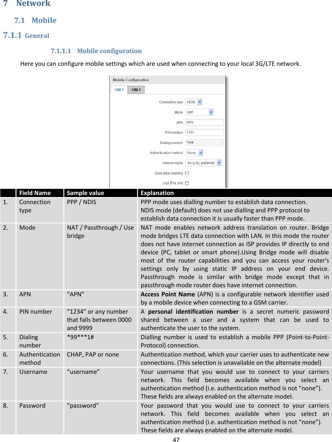
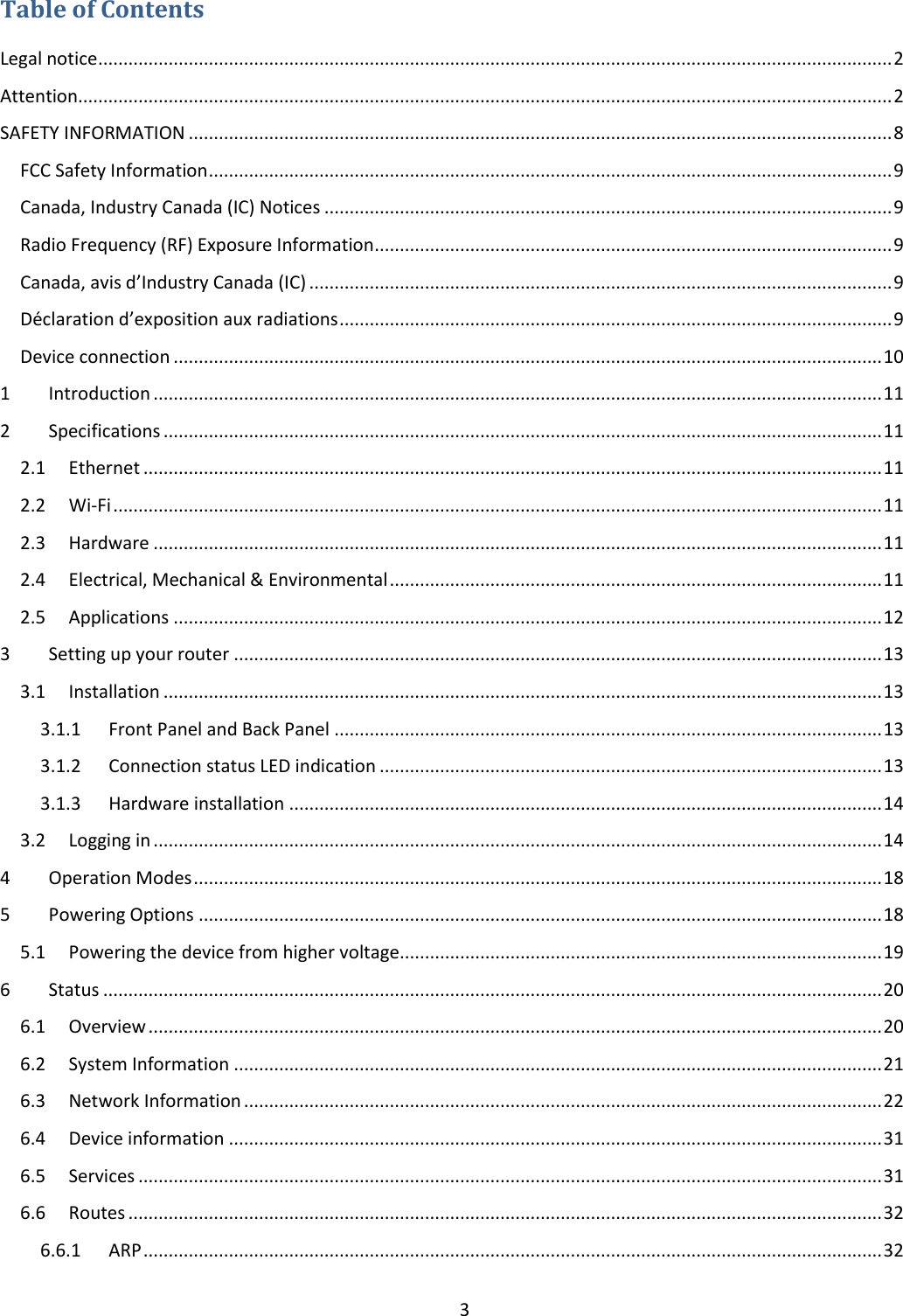
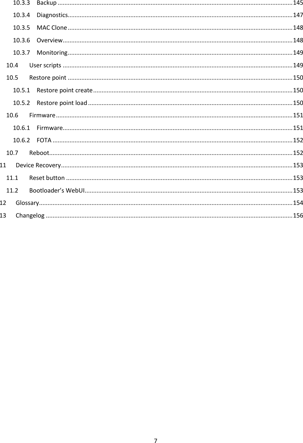
![49 7.1.1.2 Mobile Data On Demand Field name Possible values Explanation 1. Enable Enable/Disable Mobile Data On Demand function enables you to keep mobile data connection on only when it's in use 2. No data timeout(sec) 1-99999999 A mobile data connection will be terminated if no data is transferred during the timeout period 7.1.1.3 Force LTE network Field name Possible values Explanation 1. Enable Enable/Disable Enable/disable try to connect to LTE network every x seconds (used only if service mode is set to 4G (LTE) preferred) 2. Reregister Enable/Disable If this enabled, modem will be reregister before try to connect to LTE network 3. Interval (sec) 180 - 3600 Time in seconds between tries to connect to LTE network. Range [180-3600]](https://usermanual.wiki/UAB-Teltonika-Networks/RUT950.Users-Manual-1/User-Guide-3550903-Page-49.png)

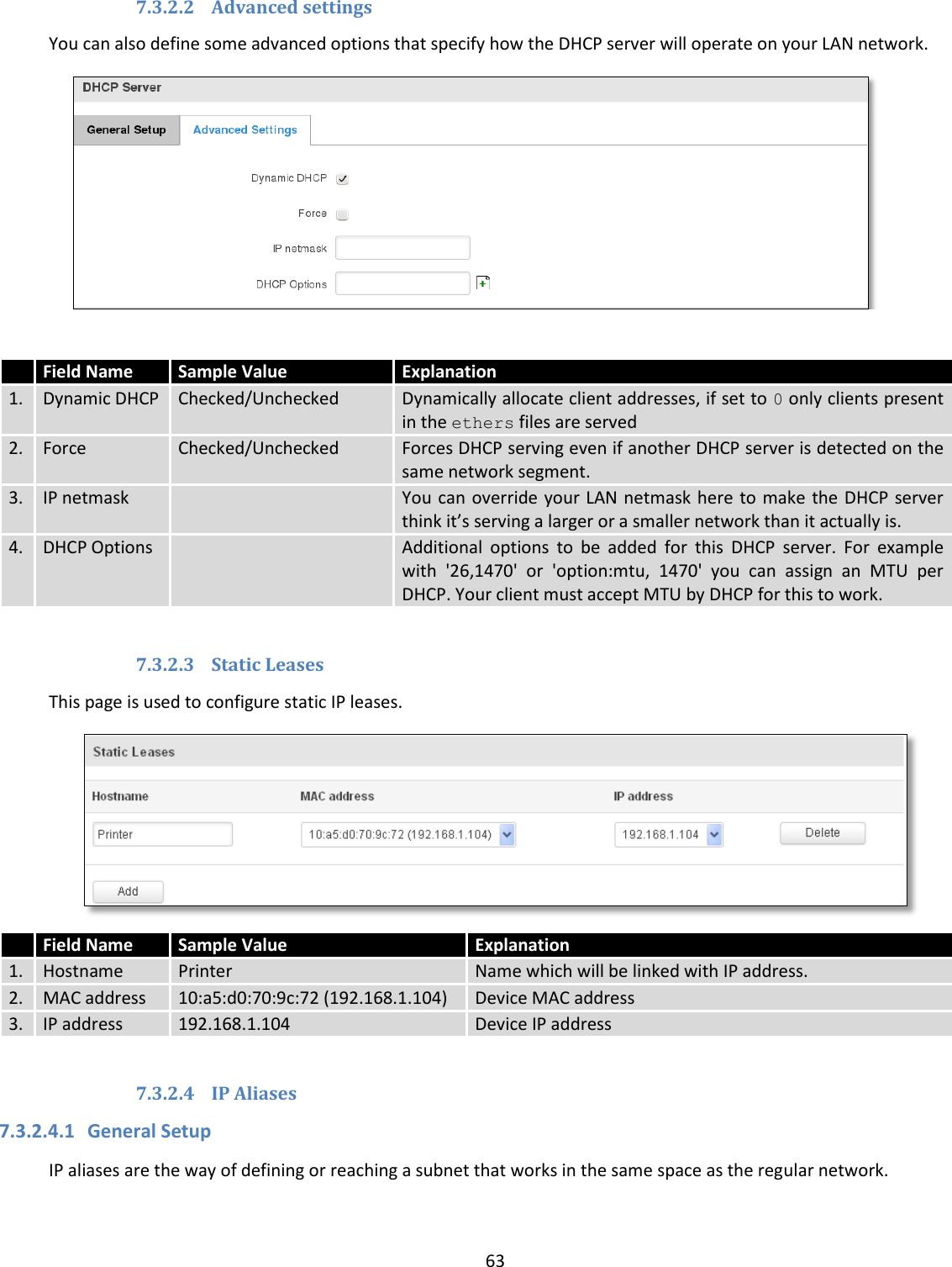
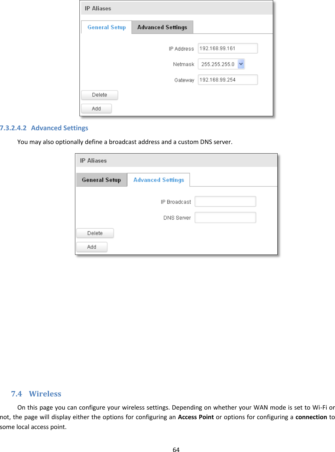
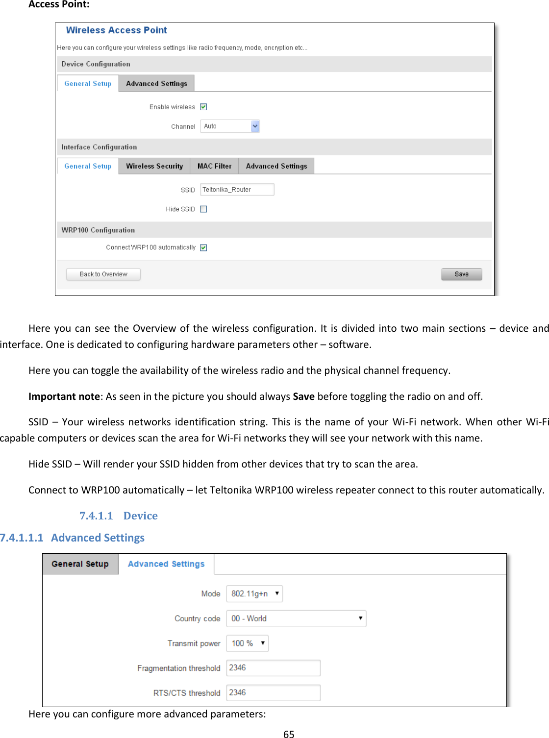
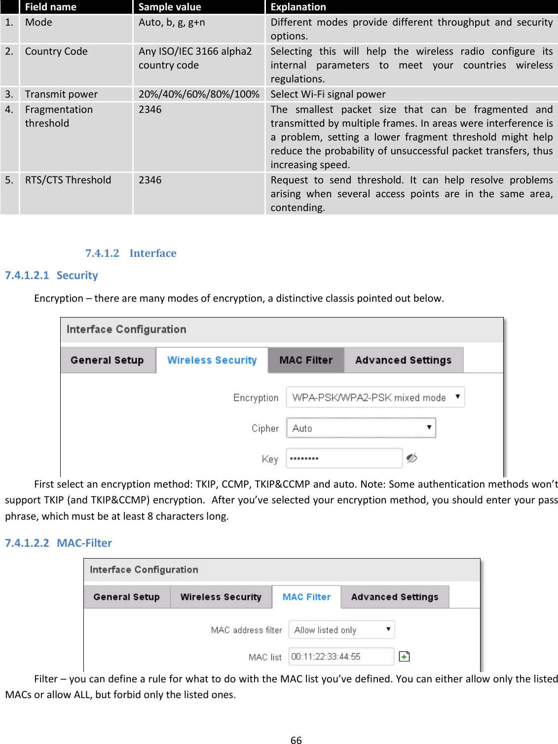
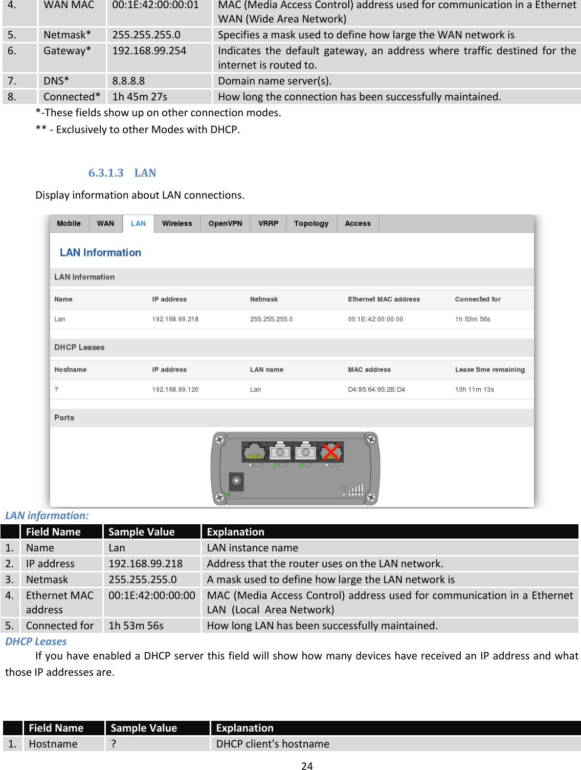
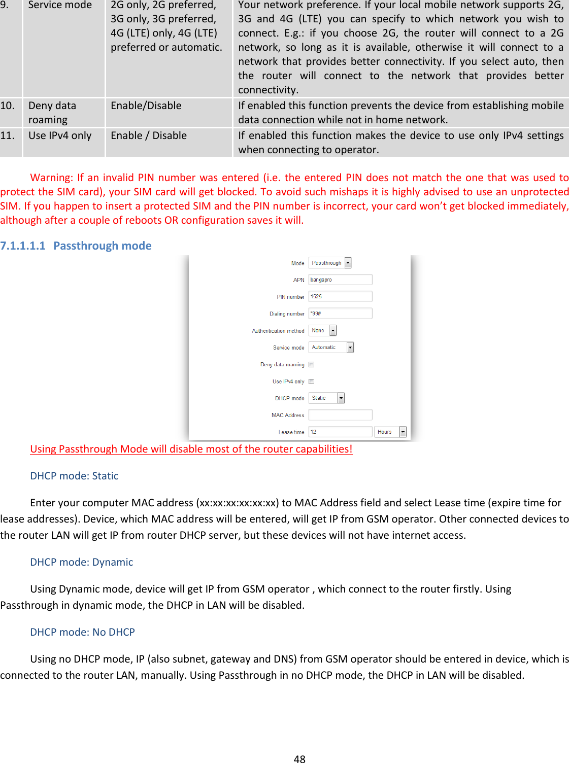
. If the Start value is set to 100 then the DHCP server will only be able to lease out addresses starting from 192.168.2.100 3. Limit 150 How many addresses the DHCP server gets to lease out. Continuing on the above example: if the start address is 192.168.2.100 then the end address will be 192.168.2.254 (100 + 155 – 1 = 254). 4. Lease time 12 How long can a leased IP be considered valid. An IP address after the specified amount of time will expire and the device that leased it out will have to request for a new one. Select Hour or Minute (minimum 2min).](https://usermanual.wiki/UAB-Teltonika-Networks/RUT950.Users-Manual-1/User-Guide-3550903-Page-62.png)