UAB Teltonika Networks RUT950 RUT950 User Manual
UAB Teltonika RUT950
UserManual.wiki
>
UAB Teltonika Networks
>
RUT950 User Manual
>
Users Manual-2
Contents
1.
Users Manual-1
2.
Users Manual-2
Users Manual-2
Navigation menu
Upload a User Manual
Namespaces
Wiki Guide
HTML
PDF
Info
Views
User Manual
Discussion / Help
Navigation
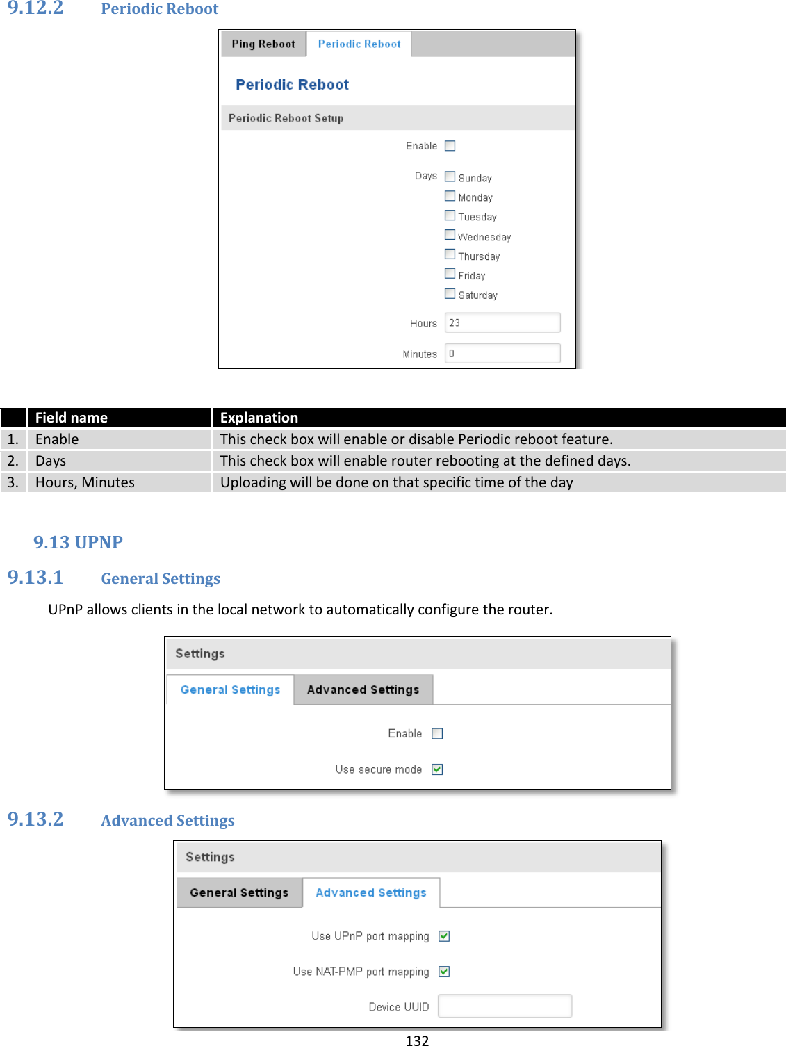
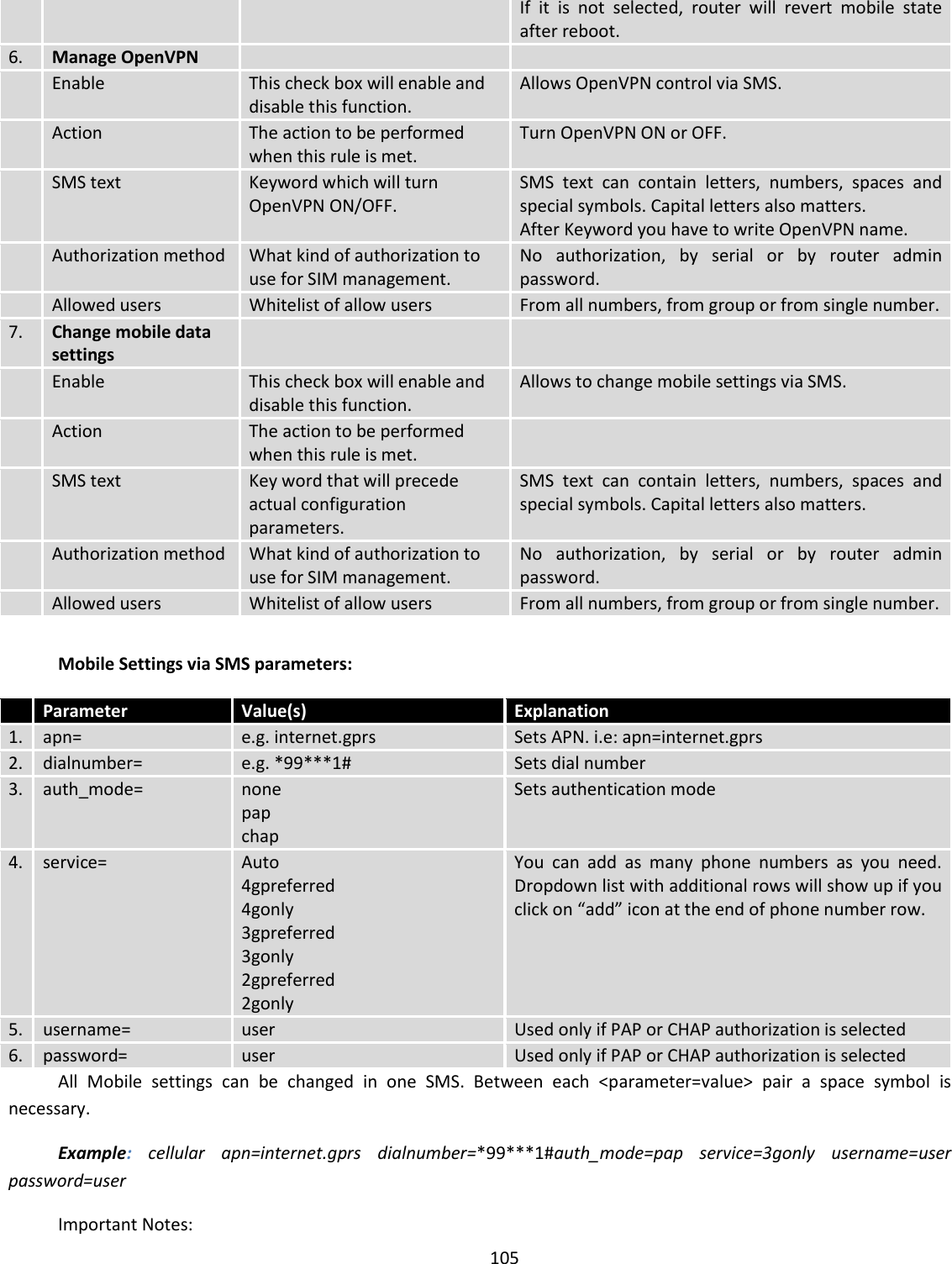
![87 Application Can obtain parameters Can set parameters 1. MQTT publisher o 2. MODBUS daemon 3. SSH 4. RMS 5. SMS 6. SNMP o 7. JSON-RPC By summarizing, RUT9XX provides several solutions for router management. Each user can choose what solution to use. If required functionality is not found in particular service, the user can combine several applications, for example, use MQTT publisher along with SNMP. Finally, if user has special needs, he can write shell script and execute it via SSH or use json-rpc. 9 Services 9.1 VRRP 9.1.1 VRRP LAN Configuration Settings Field name Sample Explanation 1. Enable Enable/Disable Enable VRRP (Virtual Router Redundancy Protocol) for LAN 2. IP address 192.168.1.253 Virtual IP address for LAN's VRRP (Virtual Router Redundancy Protocol) cluster 3. Virtual ID 1 Routers with same IDs will be grouped in the same VRRP (Virtual Router Redundancy Protocol) cluster, range [1-255] 4. Priority 100 Router with highest priority value on the same VRRP (Virtual Router Redundancy Protocol) cluster will act as a master, range [1-255]](https://usermanual.wiki/UAB-Teltonika-Networks/RUT950.Users-Manual-2/User-Guide-3550904-Page-19.png)
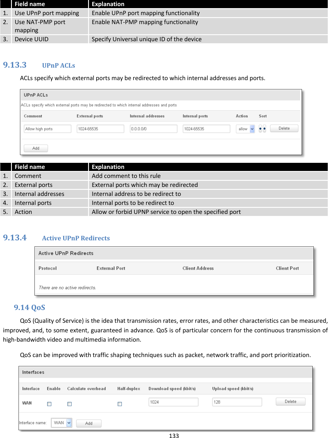
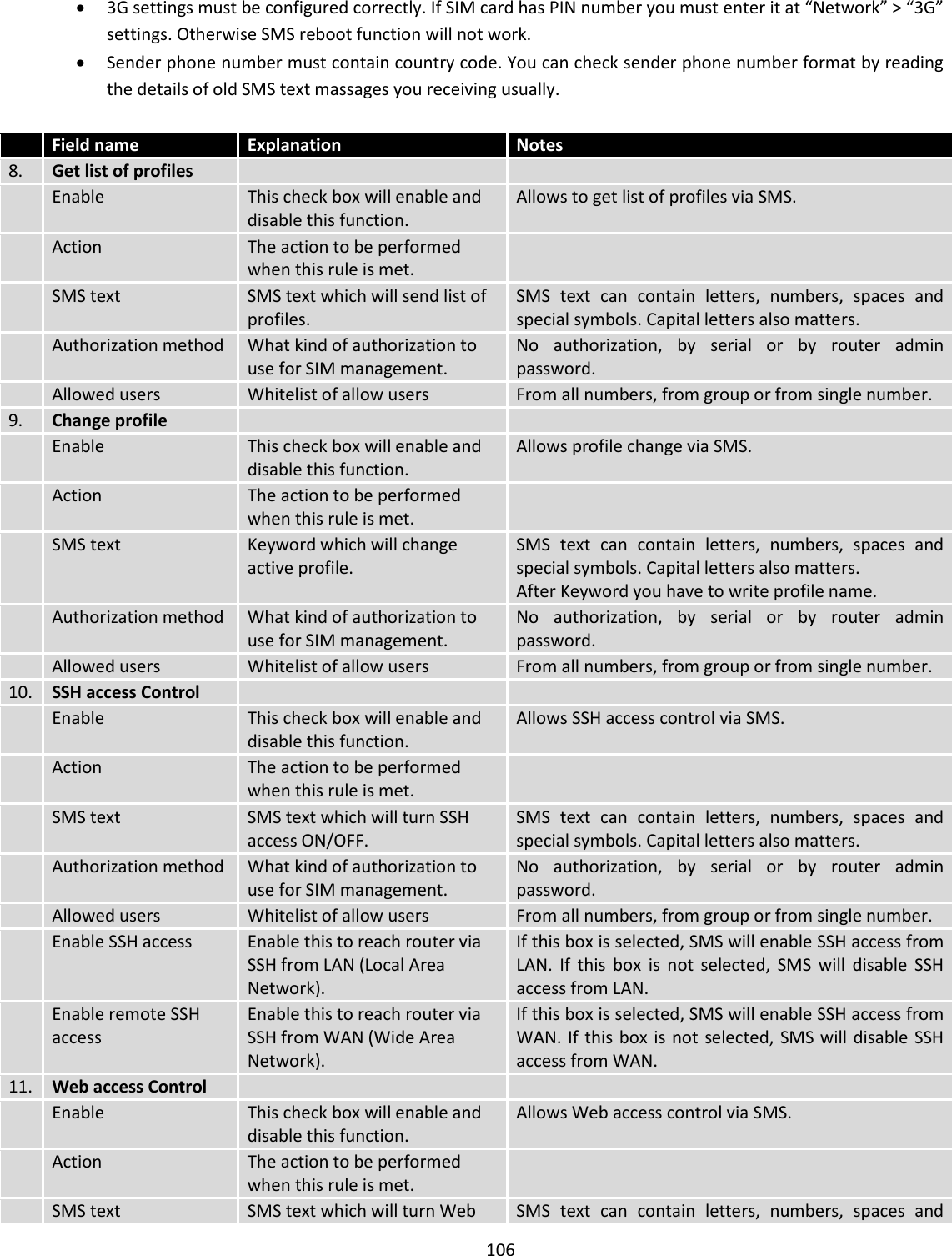
![88 9.1.2 Check Internet connection Field name Sample Explanation 1. Enable Enable/Disable Enable WAN's connection monitoring 2. Ping IP address 8.8.4.4 A host to send ICMP (Internet Control Message Protocol) packets to 3. Ping interval 10 Time interval in seconds between two Pings 4. Ping timeout (sec) 1 Response timeout value, interval [1 - 9999] 5. Ping packet size 50 ICMP (Internet Control Message Protocol) packet's size, interval [0 - 1000] 6. Ping retry count 100 Failed Ping attempt’s count before determining that connection is lost, interval [1 – 9999] 9.2 TR-069 TR-069 is a standard developed for automatic configuration and management of remote devices by Auto Configuration Servers (ACS). 9.2.1 TR-069 Parameters Configuration Field name Sample Explanation 1. Enable Enable/Disable Enable TR-069 client 2. Enable Periodic Transmission Enable / Disable Enable periodic transmissions of data to server 3. User name admin User name for authentication on TR-069 server 4. Password ******* Password for authentication on TR-069 server 5. URL http://192.168.1.110:8080 TR-069 server URL address](https://usermanual.wiki/UAB-Teltonika-Networks/RUT950.Users-Manual-2/User-Guide-3550904-Page-20.png)
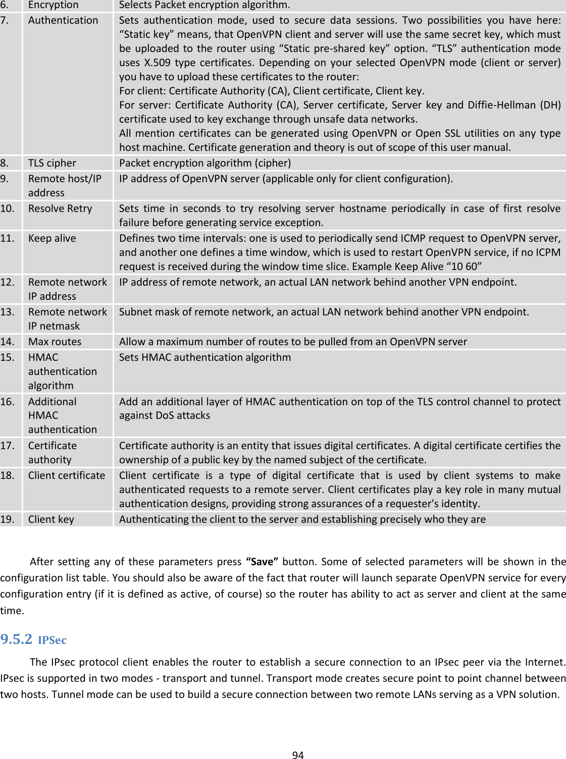
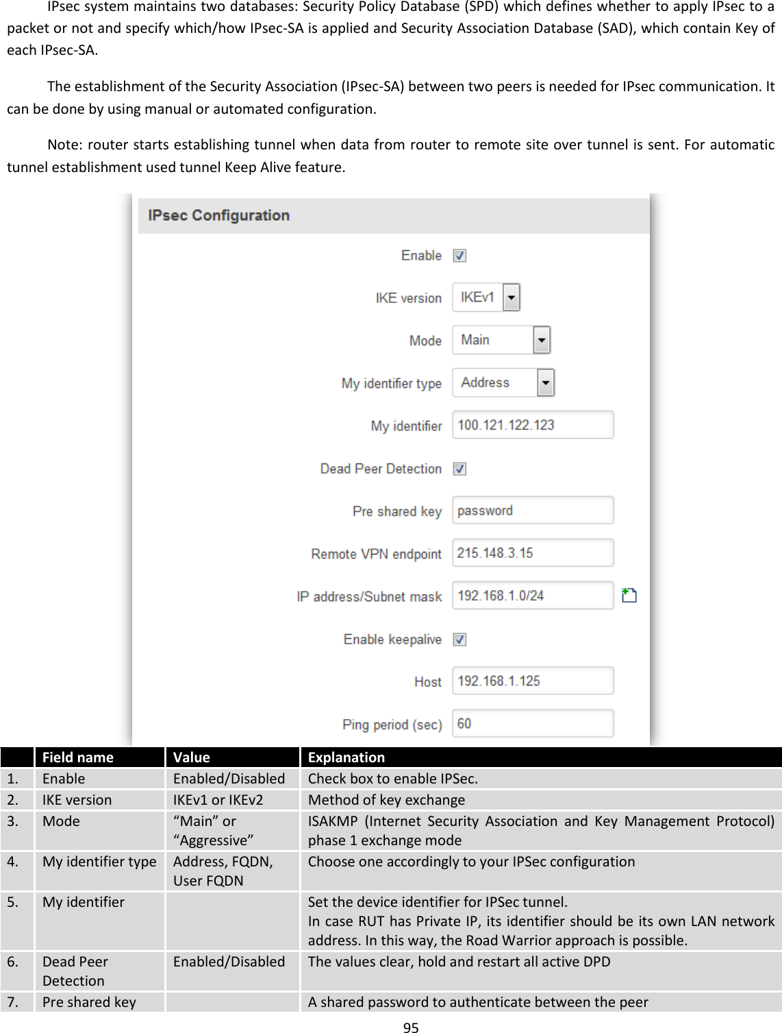
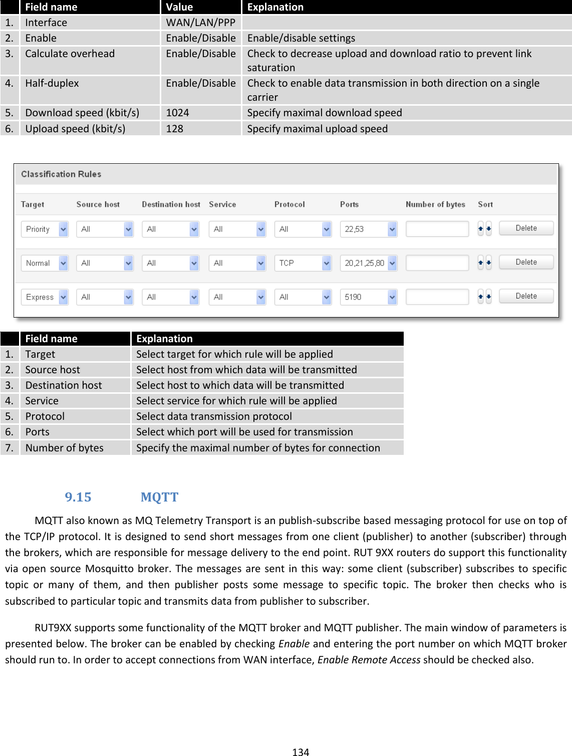
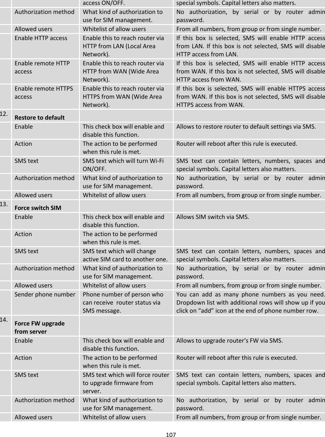
![96 8. Remote VPN endpoint Domain name or IP address. Leave empty or any 9. IP address/Subnet mask Remote network secure group IP address and mask used to determine to what subnet an IP address belongs to. Range [0-32]. IP should differ from device LAN IP 10. Enable keep alive Enabled/Disabled Enable tunnel keep alive function 11. Host A host address to which ICMP (Internet Control Message Protocol) echo requests will be send 12. Ping period (sec) Send ICMP echo request every x seconds. Range [0-999999] Phase 1 and Phase 2 must be configured accordingly to the IPSec server configuration, thus algorithms, authentication and lifetimes of each phase must be identical. Field name Value Explanation 1. Encryption algorithm DES, 3DES, AES 128, AES 192, AES256 The encryption algorithm must match with another incoming connection to establish IPSec 2. Authentication MD5, SHA1, SHA256, SHA384, SHA512 The authentication algorithm must match with another incoming connection to establish IPSec 3. Hash algorthm MD5, SHA1, SHA256, SHA384, SHA512 The hash algorithm must match with another incoming connection to establish IPSec 4. DH group MODP768, MODP1024, MODP1536, MODP2048, MODP3072, MODP4096 The DH (Diffie-Helman) group must with another incoming connection to establish IPSec 4. PFS group MODP768, MODP1024, MODP1536, MODP2048, MODP3072, MODP4096, No PFS The PFS (Perfect Forward Secrecy) group must match with another incoming connection to establish IPSec 5. Lifetime Hours, Minutes, Seconds The time duration for phase](https://usermanual.wiki/UAB-Teltonika-Networks/RUT950.Users-Manual-2/User-Guide-3550904-Page-28.png)
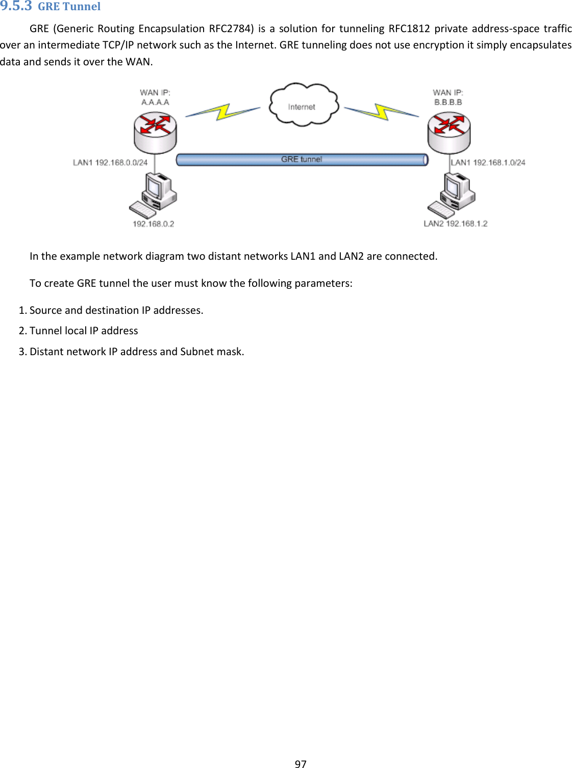
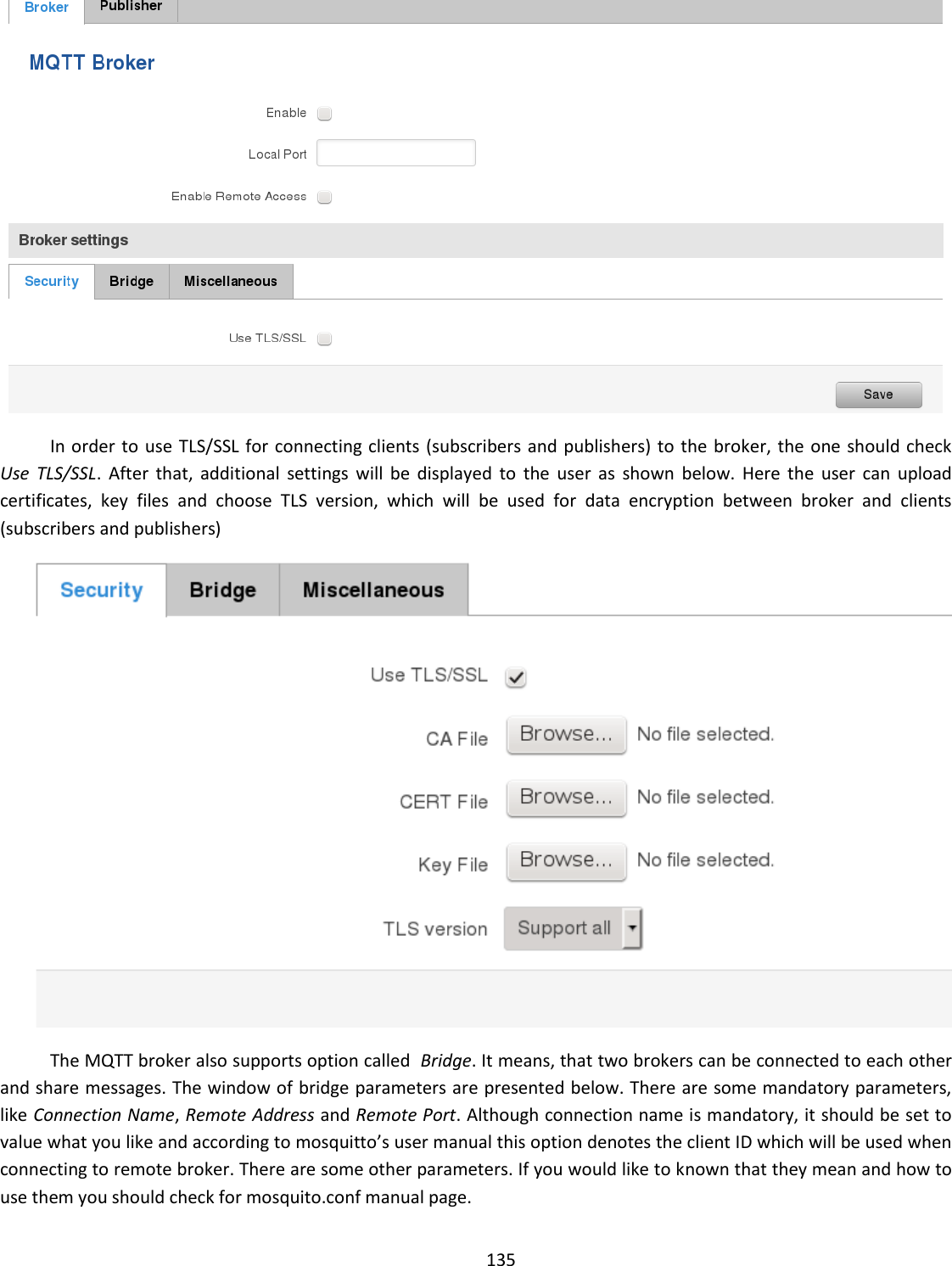
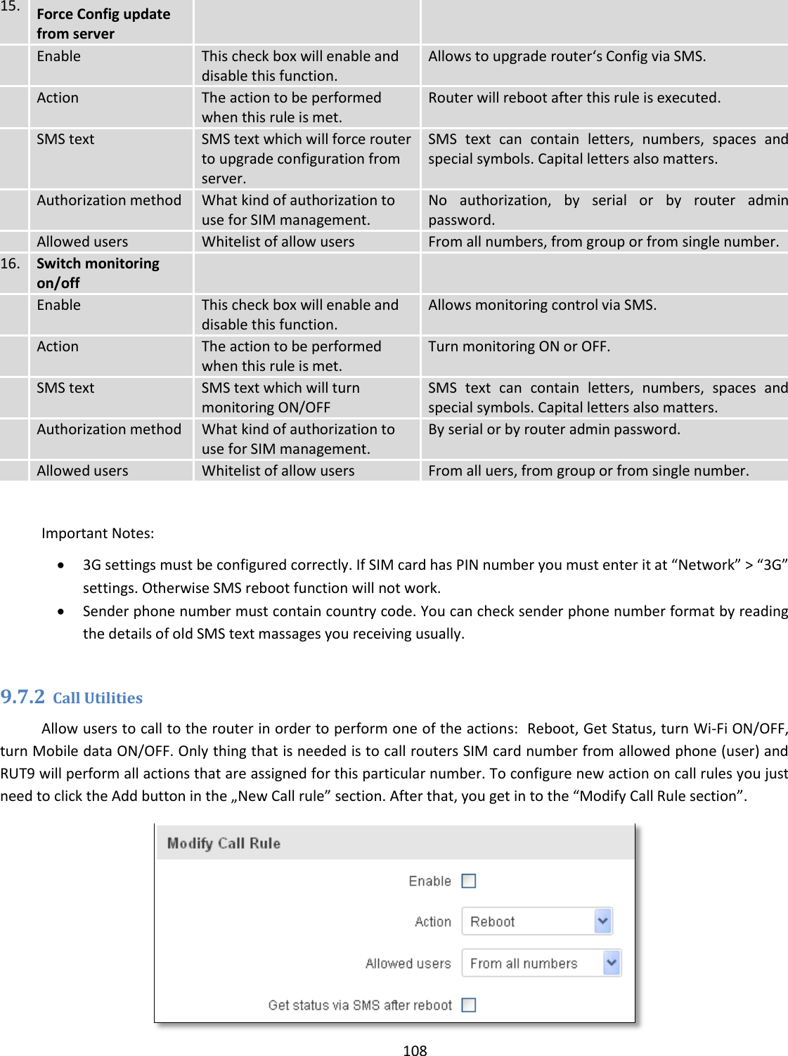
![98 Field name Explanation 1. Enabled Check the box to enable the GRE Tunnel function. 2. Remote endpoint IP address Specify remote WAN IP address. 3. Remote network IP address of LAN network on the remote device. 4. Remote network netmask Network of LAN network on the remote device. Range [0-32]. 5. Local tunnel IP Local virtual IP address. Cannot be in the same subnet as LAN network. 6. Local tunnel netmask Network of local virtual IP address. Range [0-32] 7. MTU Specify the maximum transmission unit (MTU) of a communications protocol of a layer in bytes. 8. TTL Specify the fixed time-to-live (TTL) value on tunneled packets [0-255]. The 0 is a special value meaning that packets inherit the TTL value. 9. PMTUD Check the box to enable the Path Maximum Transmission Unit Discovery (PMTUD) status on this tunnel. 10. Enable Keep alive It gives the ability for one side to originate and receive keep alive packets to and from a remote router even if the remote router does not support GRE keep alive. 11. Keep Alive host Keep Alive host IP address. Preferably IP address which belongs to the LAN network on the remote device. 12. Keep Alive interval Time interval for Keep Alive. Range [0 - 255].](https://usermanual.wiki/UAB-Teltonika-Networks/RUT950.Users-Manual-2/User-Guide-3550904-Page-30.png)

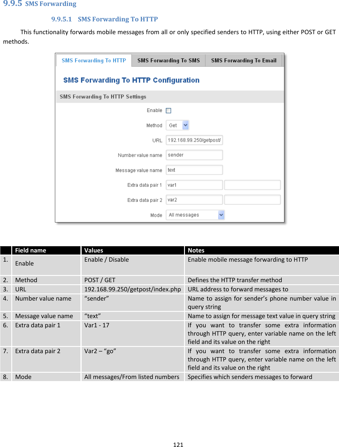
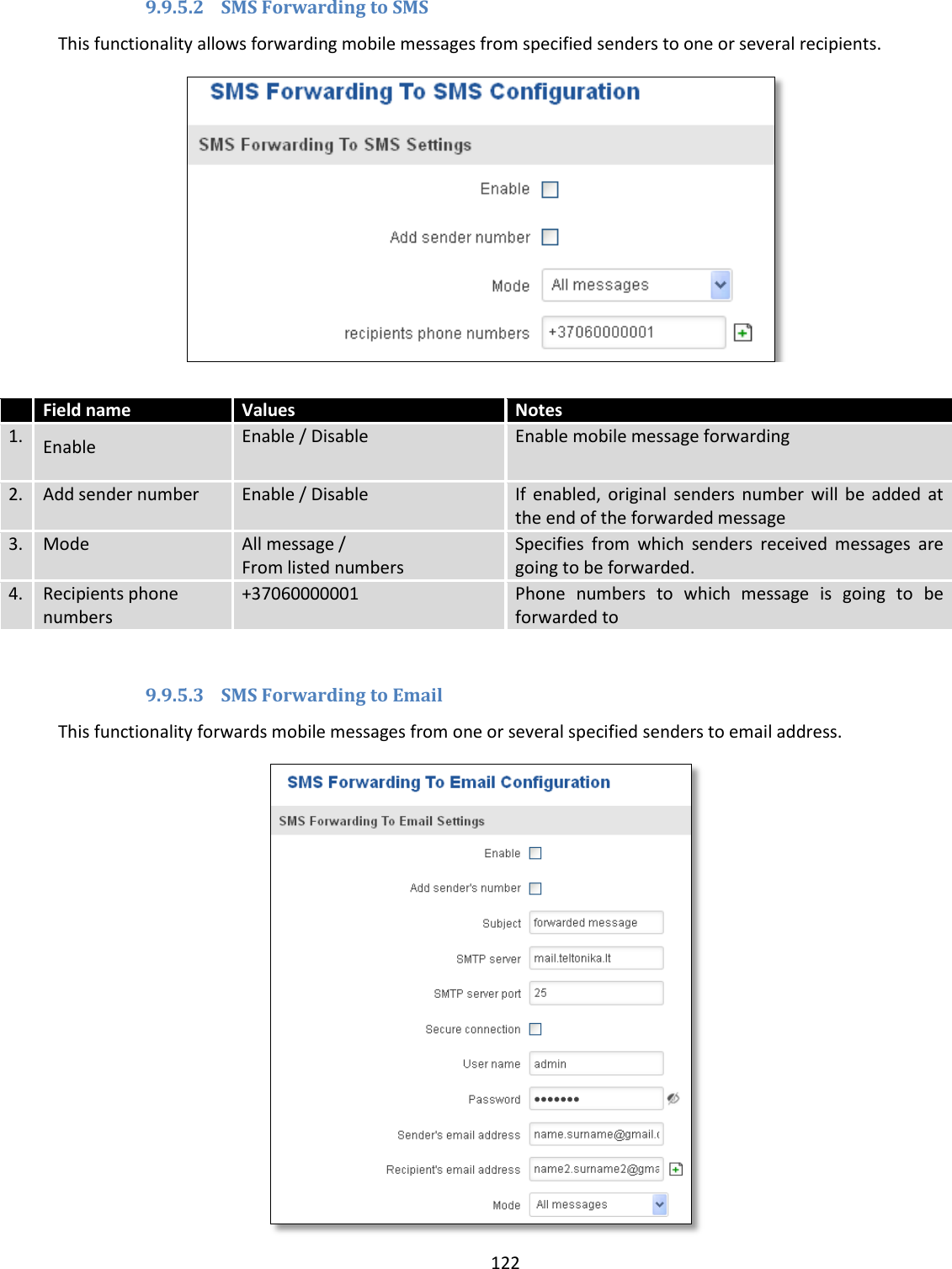
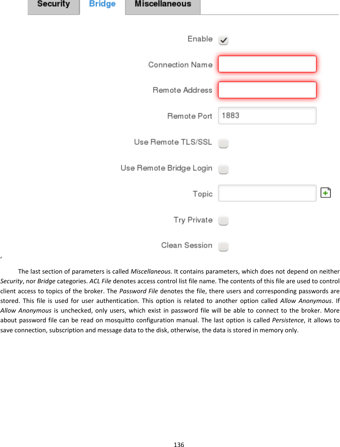
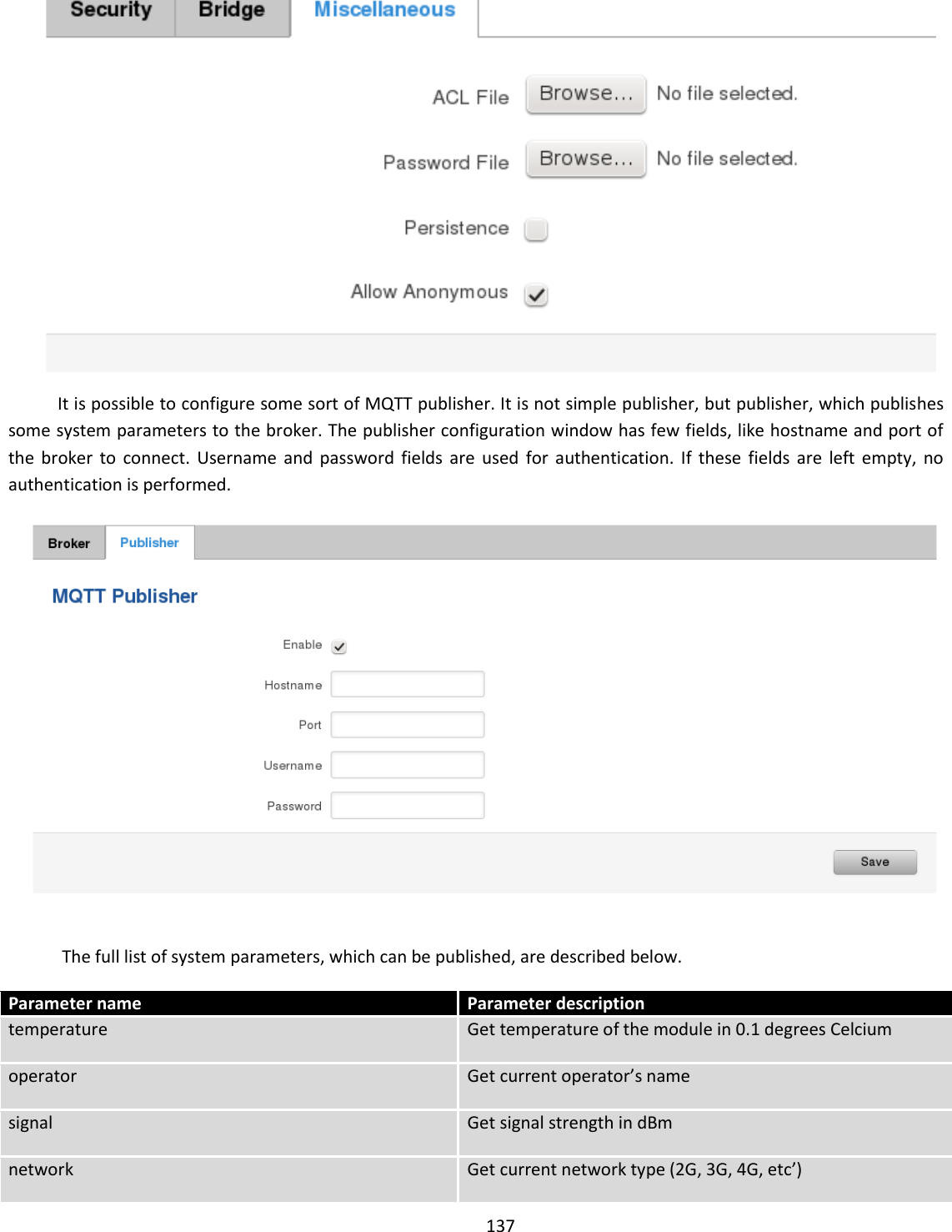
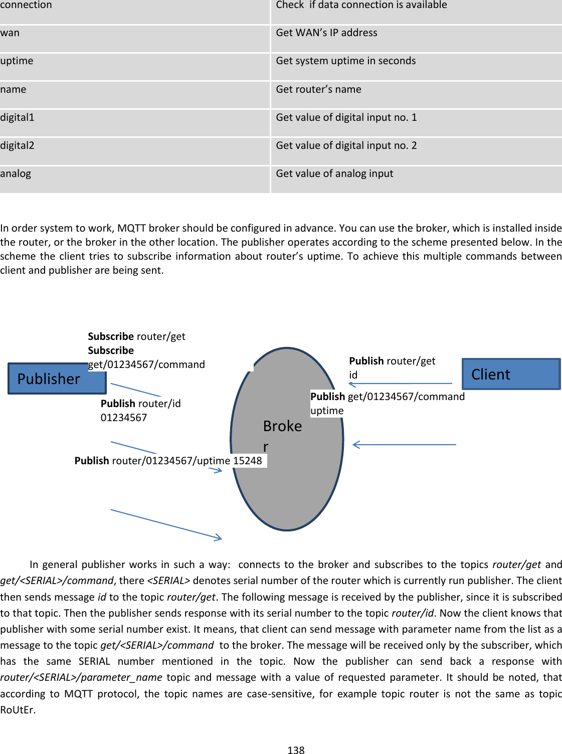
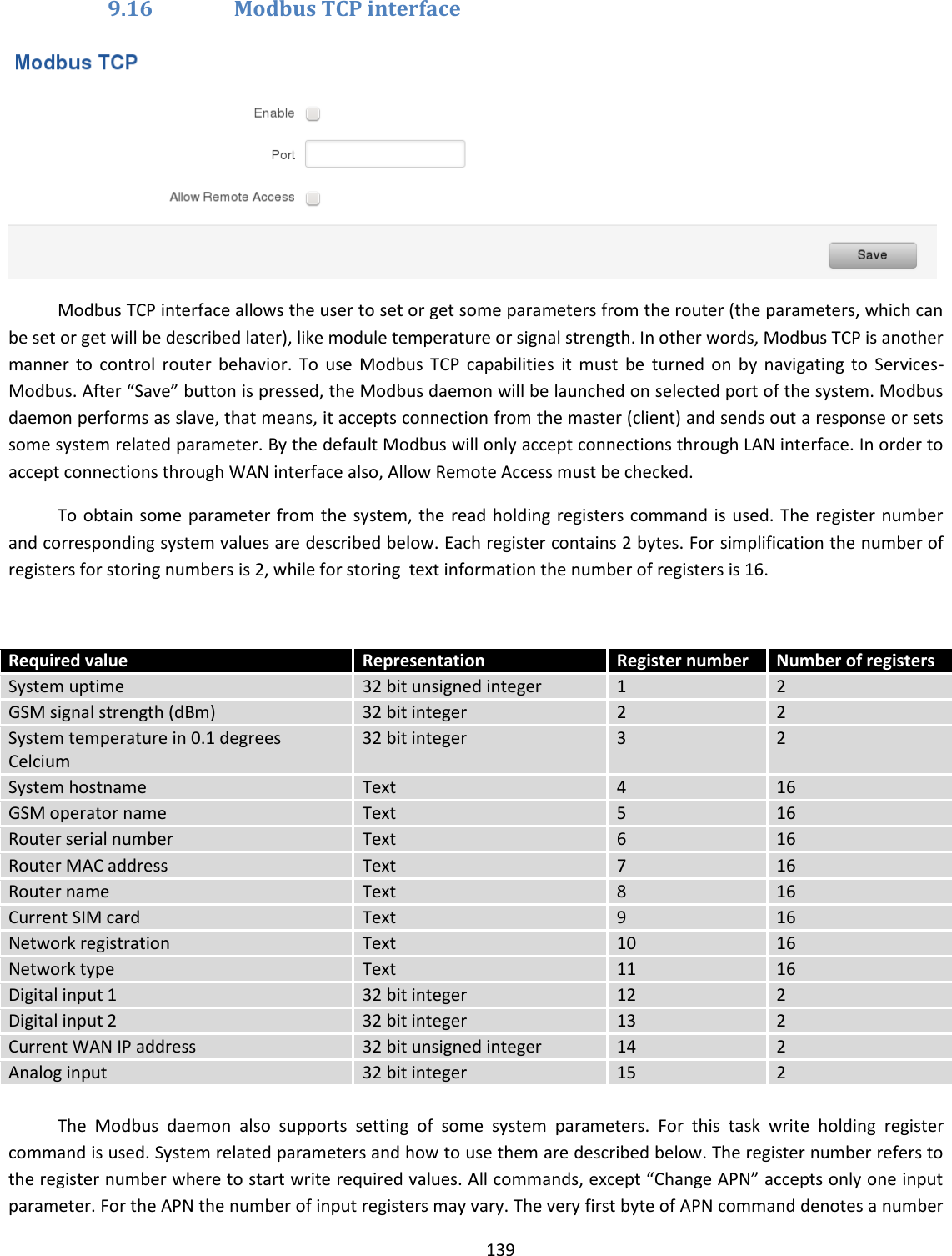
![123 Field name Values Notes 1. Enable Enable / Disable Enable mobile message forwarding to email 2. Add sender number Enable / Disable If enabled, original senders number will be added at the end of the forwarded message 3. Subject “forwarded message” Text that will be inserted in email Subject field 4. SMTP server mail.teltonika.lt Your SMTP server’s address 5. SMTP server port 25 Your SMTP server’s port number 6. Secure connection Enable / Disable Enables the use of cryptographic protocols, enable only if your SMTP server supports SSL or TLS 7. User name “admin” Your full email account user name 8. Password ******* Your email account password 9. Sender’s email address name.surname@gmail.com Your address that will be used to send emails from 10. Recipient’s email address name2.surname2@gmail.com Address that you want to forward your messages to 11. Mode All messages / from listed numbers Choose which senders messages to forward to email 9.9.6 SMPP Field name Values Explanation 1. Enable Enable/Disable Enables SMPP server 2. User name admin User name for authentication on SMPP server 3. Password ●●●●●●● Password for authentication on SMPP server 4. Server port 7777 A port will be used for SMPP server communications. Allowed all not used ports [0-65535]](https://usermanual.wiki/UAB-Teltonika-Networks/RUT950.Users-Manual-2/User-Guide-3550904-Page-55.png)