UAB Teltonika Networks RUT950 RUT950 User Manual
UAB Teltonika RUT950
Contents
- 1. Users Manual-1
- 2. Users Manual-2
Users Manual-2
69
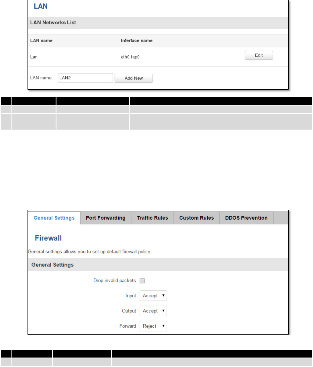
7.5.2 LAN Networks
In this page you can create extra LAN networks, and assign them with LAN Ports and wireless access points. You
can get extra information on how to configure any of your LAN’s settings in section – 7.3 LAN
Field Name
Sample Value
Explanation
1.
LAN name
Lan
Specifies new LAN name
2.
Interface
name
eth0 tap0
Specifies LAN interface name
7.6 Firewall
In this section we will look over the various firewall features that come with RUT9.
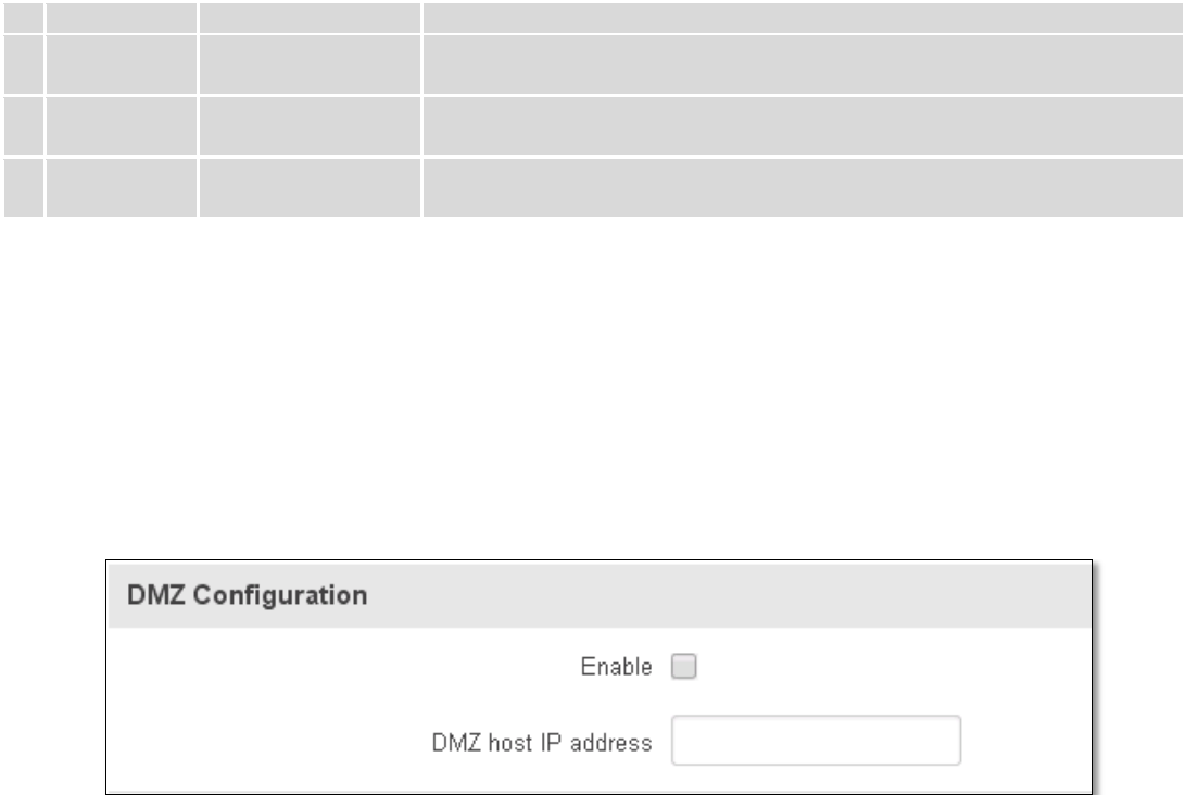
7.6.1 General Settings
The routers firewall is a standard Linux iptables package, which uses routing chains and policies to facilitate
control over inbound and outbound traffic.
Field Name
Sample value
Explanation
1.
Drop Invalid
Checked/Unchecked
A “Drop” action is performed on a packet that is determined to be invalid
70
packets
2.
Input
Reject/Drop/Accept
DEFAULT* action that is to be performed for packets that pass through the
Input chain.
3.
Output
Reject/Drop/Accept
DEFAULT* action that is to be performed for packets that pass through the
Output chain.
4.
Forward
Reject/Drop/Accept
DEFAULT* action that is to be performed for packets that pass through the
Forward chain.
*DEFAULT: When a packet goes through a firewall chain it is matched against all the rules for that specific chain. If
no rule matches said packet, an according Action (either Drop or Reject or Accept) is performed.
Accept – Packet gets to continue down the next chain.
Drop – Packet is stopped and deleted.
Reject – Packet is stopped, deleted and, differently from Drop, an ICMP packet containing a message of rejection
is sent to the source of the dropped packet.
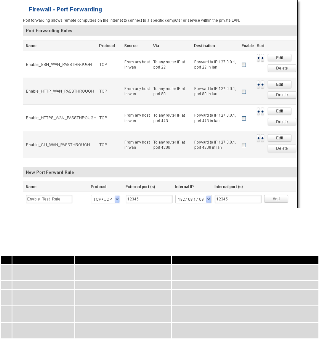
7.6.2 DMZ
By enabling DMZ for a specific internal host (for e.g.: your computer), you will expose that host and its services to
the routers WAN network (i.e. - internet).
7.6.3 Port Forwarding
Here you can define your own port forwarding rules.
71
You can use port forwarding to set up servers and services on local LAN machines. The above picture shows how
you can set up a rule that would allow a website that is being hosted on 192.168.1.109, to be reached from the outside
by entering http://routersExternalIp:12345/.
Field Name
Sample value
Explanation
1.
Name
Enable_SSH_WAN_PASSTHROUGH
Name of the rule. Used purely to make it easier to
manage rules.
2.
Protocol
TCP/UDP/TCP+UDP/Other
Type of protocol of incoming packet.
3.
External Port
1-65535
From this port on the WAN network the traffic will be
forwarded.
4.
Internal IP address
IP address of some computer on
your LAN
The IP address of the internal machine that hosts
some service that we want to access from the outside.
5.
Internal port
1-65535
To that port on the internal machine the rule will
redirect the traffic.
When you click edit you can fine tune a rule to near perfection, if you should desire that.
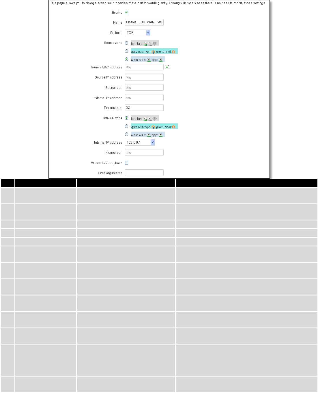
72
Field Name
Sample value
Explanation
1.
Name
ENABLE_SSH_WAN_PASSTHROUGH
Name of the rule. Used purely to make it easier to
manage rules.
2.
Protocol
TCP/UDP/TCP+
UDP/ICMP/Custom
You may specify multiple by selecting (custom) and
then entering protocols separated by space
3.
Source zone
LAN/VPN/WAN
Match incoming traffic from this zone only
4.
Source MAC address
any
Match incoming traffic from these MACs only
5.
Source IP address
any
Match incoming traffic from this IP or range only
7.
Source port
any
Match incoming traffic originating from the given
source port or port range on the client host only
8.
External IP address
any
Match incoming traffic directed at the given IP
address only
9.
External port
22
Match incoming traffic directed at the given
destination port or port range on this host only
10.
Internal zone
LAN/VPN/WAN
Redirect matched incoming traffic to the specified
internal zone
11.
Internal IP address
127.0.0.1
Redirect matched incoming traffic to the specified
internal host
12.
Internal port
any
Redirect matched incoming traffic to the given port
on the internal host
13.
Enable NAT loopback
Enable/Disable
NAT loopback enables your local network (i.e.
behind your router/modem) to connect to a
forward-facing IP address (such as 208.112.93.73) of
a machine that it also on your local network
14.
Extra arguments
Passes additional arguments to iptables. Use with
care!
73
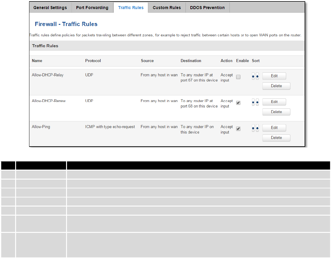
7.6.4 Traffic Rules
The traffic rule page contains a more generalized rule definition. With it you can block or open ports, alter how
traffic is forwarded between LAN and WAN and many more things.
Field Name
Explanation
1.
Name
Name of the rule. Used for easier rules management purpose only
2.
Protocol
Protocol type of incoming or outgoing packet
3.
Source
Match incoming traffic from this IP or range only
4.
Destination
Redirect matched traffic to the given IP address and destination port
5.
Action
Action to be taken for the packet if it matches the rule
6.
Enable
Self-explanatory. Uncheck to make the rule inactive. The rule will not be deleted, but it also
will not be loaded into the firewall.
7.
Sort
When a packet arrives, it gets checked for a matching rule. If there are several rules that
match the rule, the first one is applied i.e. the order of the rule list impacts how your firewall
operates, therefore you are given the ability to sort your list as you wish.
You can configure firewall rule by clicking edit button.
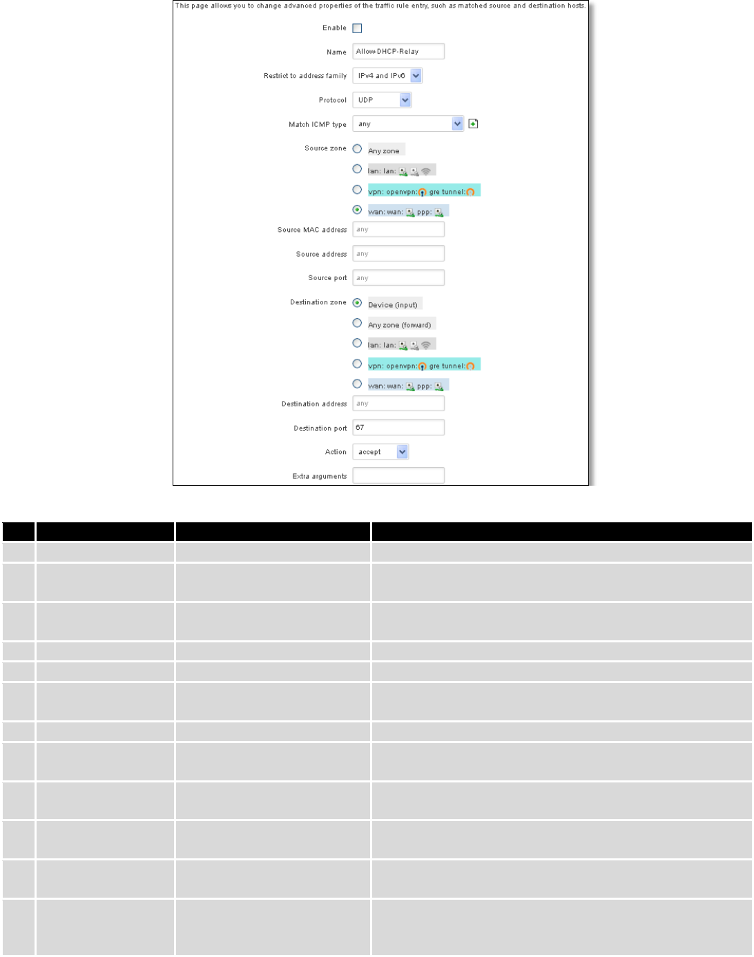
74
Field Name
Sample value
Explanation
1.
Name
“Allow-DHCP-Relay”
Used to make rule management easier
2.
Restrict to address
family
IPv4 and IPV6
Match traffic from selected address family only
3.
Protocol
TCP/UDP/Any/ICMP/Custom
Protocol of the packet that is being matched against traffic
rules.
4.
Match ICMP type
any
Match traffic with selected ICMP type only
5.
Source zone
any zone/LAN/VPN/WAN
Match incoming traffic from this zone only
6.
Source MAC
address
any
Match incoming traffic from these MACs only
7.
Source address
any
Match incoming traffic from this IP or range only
8.
Source port
any
Match incoming traffic originating from the given source
port or port range on the client host only
9.
Destination zone
Device/Any
zone/LAN/VPN/WAN
Match forwarded traffic to the given destination zone only
10.
Destination address
any
Match forwarded traffic to the given destination IP address
or IP range only
11.
Destination port
67
Match forwarded traffic to the given destination port or
port range only
12.
Action
Drop/Accept/Reject + chain
+ additional rules
Action to be taken on the packet if it matches the rule. You
can also define additional options like limiting packet
volume, and defining to which chain the rule belongs
75
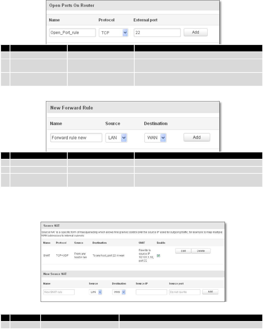
7.6.4.1 Open Ports On the Router
Field Name
Sample value
Explanation
1.
Name
Open_Port_rule
Used to make rule management easier
2.
Protocol
TCP/UDP/Any/ICMP/Custom
Protocol of the packet that is being matched against
traffic rules.
3.
External port
1-65535
Match incoming traffic directed at the given destination
port or port range on this host.
7.6.4.2 New Forward Rule
Field Name
Sample value
Explanation
1.
Name
Forward rule new
Used to make rule management easier
2.
Source
LAN/VPN/WAN
Match incoming traffic from selected address family only
3.
Protocol
TCP/UDP/Any/ICMP/Custom
Protocol of the packet that is being matched against
traffic rules.
7.6.4.3 Source NAT
Source NAT is a specific form of masquerading which allows fine grained control over the source IP used for
outgoing traffic, for example to map multiple WAN addresses to internal subnets.
Field Name
Sample value
Explanation
1.
Name
SNAT
Used to make rule management easier
76
2.
Protocol
TCP/UDP/Any/ICMP/Custom
Protocol of the packet that is being matched against traffic
rules.
3.
Source
LAN/VPN/WAN
Match incoming traffic from selected address family only
4.
Destination
LAN/VPN/WAN
Forward incoming traffic to selected address family only
5.
SNAT
Rewrite to source IP 10.101.1.10
SNAT (Source Network Address Translation) rewrite packet\'s
source IP address and port
6.
Enable
Enable/Disable
Make a rule active/inactive
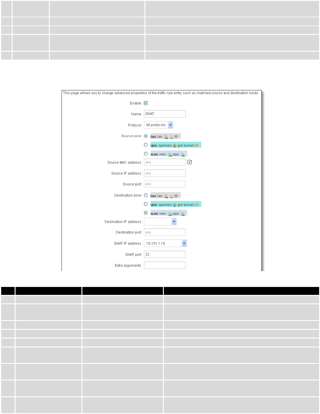
You can configure firewall source NAT rule, by clicking edit button.
Field Name
Sample value
Explanation
1.
Name
SNAT
Used to make rule management easier
2.
Protocol
TCP/UDP/Any/ICMP/Custom
Protocol of the packet that is being matched against
traffic rules.
3.
Source zone
LAN/VPN/WAN
Match incoming traffic from this zone only
4.
Source MAC address
any
Match incoming traffic from these MACs only
5.
Source address
any
Match incoming traffic from this IP or range only
6.
Source port
any
Match incoming traffic originating from the given source
port or port range on the client host only
7.
Destination zone
LAN/VPN/WAN
Match forwarded traffic to the given destination zone
only
8.
Destination IP address
Select from the list
Match forwarded traffic to the given destination IP
address or IP range only
9.
Destination port
any
Match forwarded traffic to the given destination port or
port range only
77
10.
SNAT IP address
“10.101.1.10”
Rewrite matched traffic to the given IP address
11.
SNAT port
“22”
Rewrite matched traffic to the given source port. May be
left empty to only rewrite the IP address'
12.
Extra arguments
Passes additional arguments to iptables. Use with care!
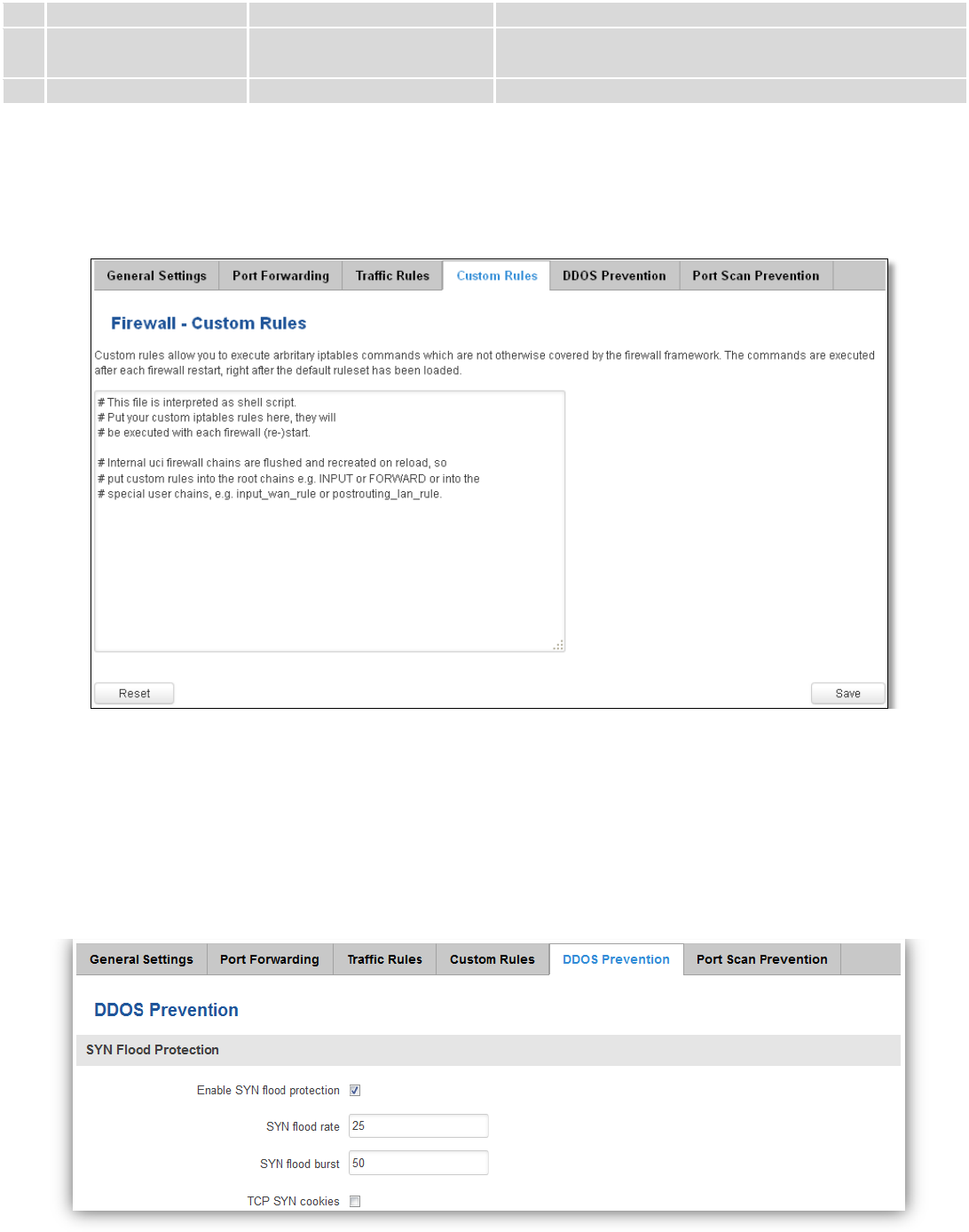
7.6.5 Custom Rules
Here you have the ultimate freedom in defining your rules – you can enter them straight into the iptables
program. Just type them out into the text field ant it will get executed as a Linux shell script. If you are unsure of how to
use iptables, check out the internet for manuals, examples and explanations.
7.6.6 DDOS Prevention
7.6.6.1 SYN Flood Protection
SYN Flood Protection allows you to protect from attack that exploits part of the normal TCP three-way handshake
to consume resources on the targeted server and render it unresponsive. Essentially, with SYN flood DDoS, the offender
sends TCP connection requests faster than the targeted machine can process them, causing network saturation.
78
Field Name
Sample value
Explanation
1.
Enable SYN flood protection
Enable/Disable
Makes router more resistant to SYN flood attacks.
2.
SYN flood rate
“25”
Set rate limit (packets/second) for SYN packets above
which the traffic is considered a flood.
3.
SYN flood burst
“50”
Set burst limit for SYN packets above which the traffic is
considered a flood if it exceeds the allowed rate.
4.
TCP SYN cookies
Enable/Disable
Enable the use of SYN cookies (particular choices of
initial TCP sequence numbers by TCP servers).
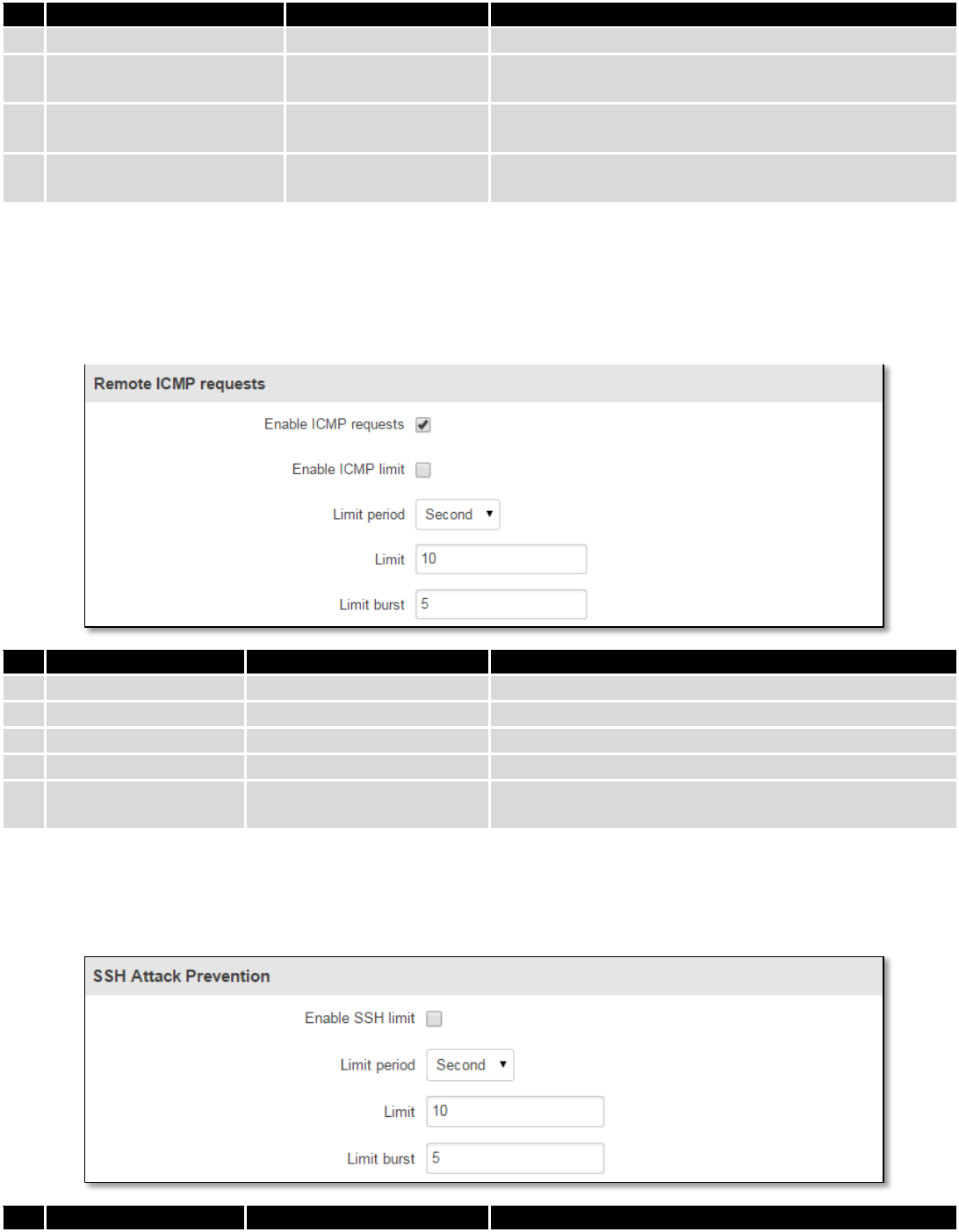
7.6.6.2 Remote ICMP requests
Attackers are using ICMP echo request packets directed to IP broadcast addresses from remote locations to
generate denial-of-service attacks.
Field Name
Sample value
Explanation
1.
Enable ICMP requests
Enable/Disable
Blocks remote ICMP echo-request type
2.
Enable ICMP limit
Enable/Disable
Enable ICMP echo-request limit in selected period
3.
Limit period
Second/Minute/Hour/Day
Select in what period limit ICMP echo-request
4.
Limit
“10”
Maximum ICMP echo-request during the period
5.
Limit burst
“5”
Indicating the maximum burst before the above limit
kicks in.
7.6.6.3 SSH Attack Prevention
Prevent SSH (Allows a user to run commands on a machine's command prompt without them being physically
present near the machine.) attacks by limiting connections in defined period.
Field Name
Sample value
Explanation
79
1.
Enable SSH limit
Enable/Disable
Enable SSH connections limit in selected period
2.
Limit period
Second/Minute/Hour/Day
Select in what period limit SSH connections
3.
Limit
“10”
Maximum SSH connections during the period
4.
Limit burst
“5”
Indicating the maximum burst before the above limit
kicks in.
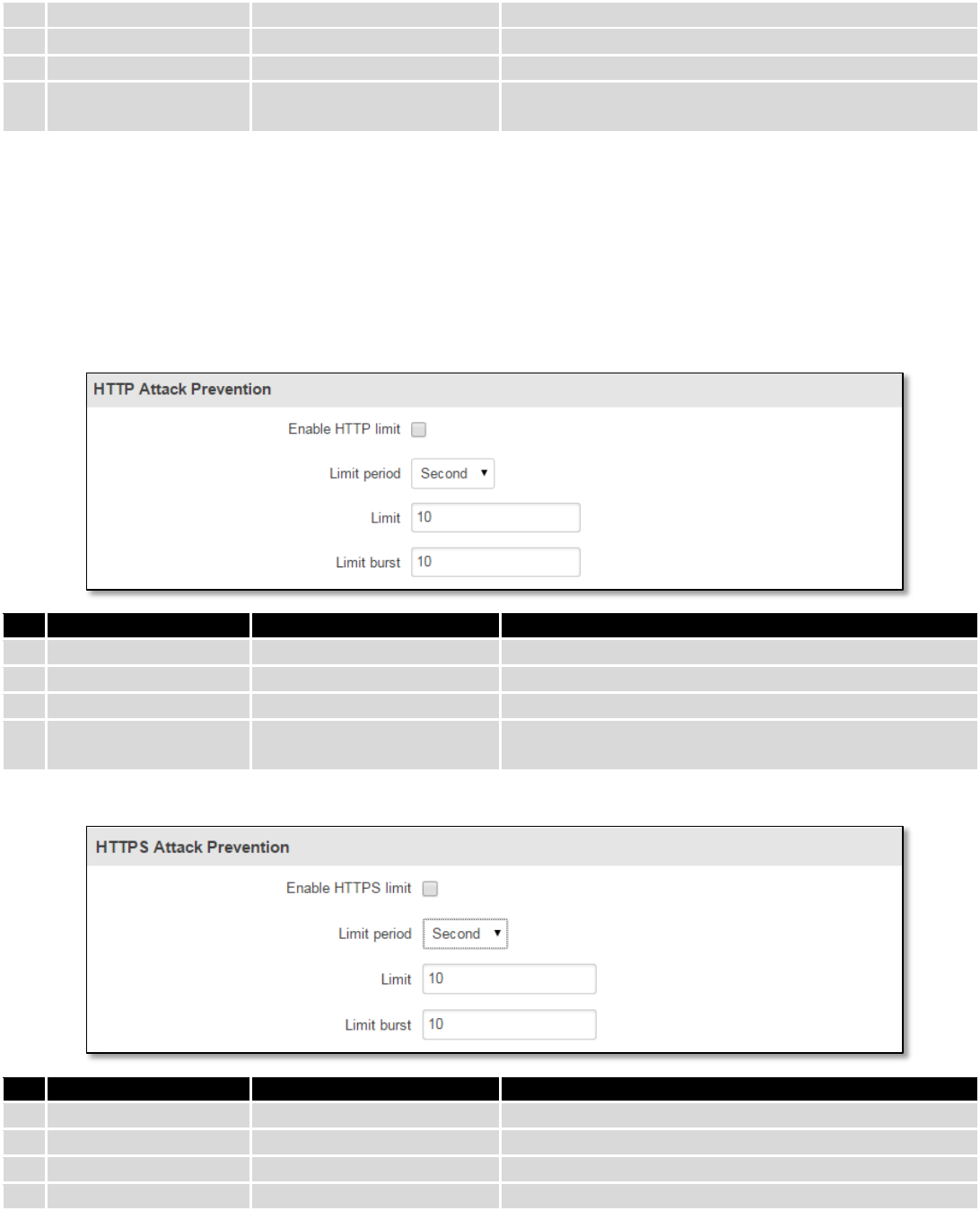
7.6.6.4 HTTP Attack Prevention
HTTP attack sends a complete, legitimate HTTP header, which includes a 'Content-Length' field to specify the size
of the message body to follow. However, the attacker then proceeds to send the actual message body at an extremely
slow rate (e.g. 1 byte/110 seconds). Due to the entire message being correct and complete, the target server will
attempt to obey the 'Content-Length' field in the header, and wait for the entire body of the message to be transmitted,
hence slowing it down.
Field Name
Sample value
Explanation
1.
Enable HTTP limit
Enable/Disable
Limits HTTP connections per period
2.
Limit period
Second/Minute/Hour/Day
Select in what period limit HTTP connections
3.
Limit
“10”
Maximum HTTP connections during the period
4.
Limit burst
“10”
Indicating the maximum burst before the above limit
kicks in.
7.6.6.5 HTTPS Attack Prevention
Field Name
Sample value
Explanation
1.
Enable HTTPS limit
Enable/Disable
Limits HTTPS connections per period
2.
Limit period
Second/Minute/Hour/Day
Select in what period limit HTTPS connections
3.
Limit
“10”
Maximum HTTPS connections during the period
4.
Limit burst
“10”
Indicating the maximum burst
80
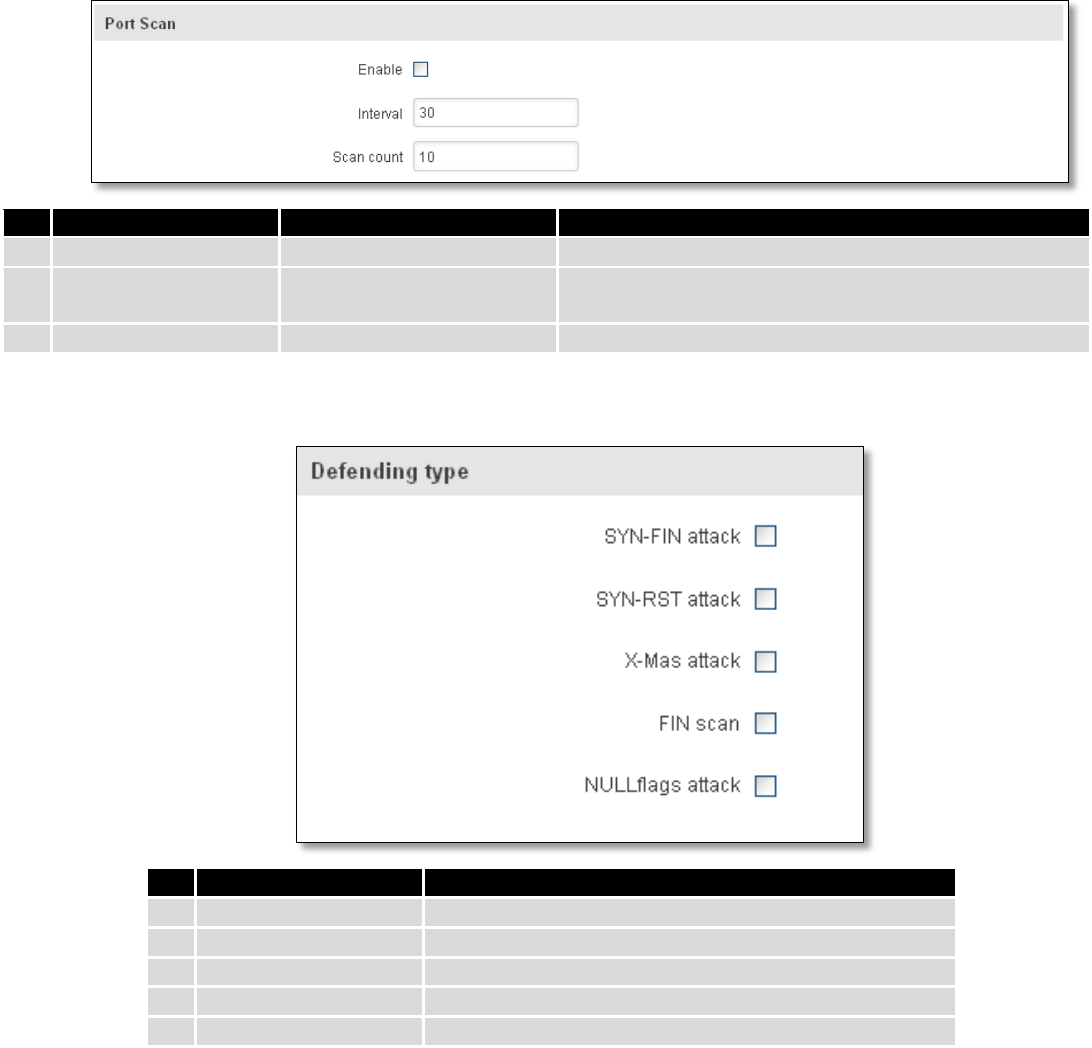
7.6.7 Port Scan Prevention
7.6.7.1 Port Scan
Field Name
Sample value
Explanation
1.
Enable
Enable/Disable
Enable port scan prevention
2.
Interval
30
Time interval in seconds counting how much port scan
(10 – 60 sec.)
3.
Scan count
10
How much port scan before blocked
7.6.7.2 Defending type
Field Name
Explanation
1.
SYN-FIN attack
Protect from SYN-FIN attack
2.
SYN-RST attack
Protect from SYN-RST attack
3.
X-Mas attack
Protect from X-Mas attack
4.
FIN scan
Protect from FIN scan
5.
NULLflags attack
Protect from NULLflags attack
7.7 Routing
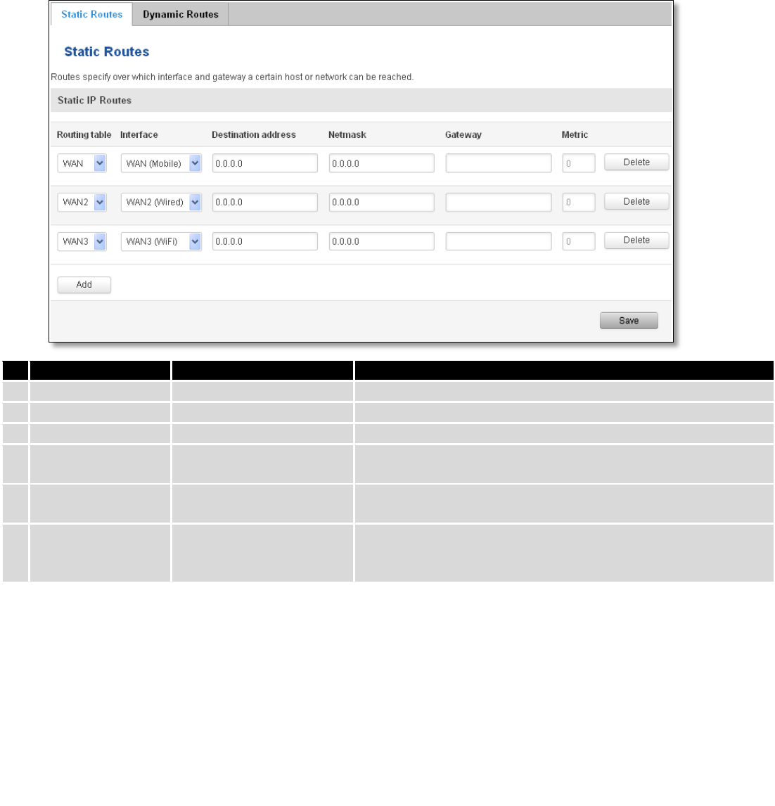
7.7.1 Static Routes
Static routes specify over which interface and gateway a certain host or network can be reached.
81
Field name
Value
Explanation
1.
Routing table
MAIN/WAN/WAN2/WAN3
Defines the table to use for the route
2.
Interface
MAIN/WAN/WAN2/WAN3
The zone where the target network resides
3.
Destination address
IP address
The address of the destination network
4.
Netmask
IP mask
Mask that is applied to the Target to determine to what actual
IP addresses the routing rule applies
5.
Gateway
IP address
To where the router should send all the traffic that applies to
the rule
6.
Metric
integer
Used as a sorting measure. If a packet about to be routed fits
two rules, the one with the higher metric is applied.
Additional note on Target & Netmask: You can define a rule that applies to a single IP like this: Target - some IP;
Netmask - 255.255.255.255. Furthermore you can define a rule that applies to a segment of IPs like this: Target – some
IP that STARTS the segment; Netmask – Netmask that defines how large the segment is. E.g.:
192.168.55.161
255.255.255.255
Only applies to 192.168.55.161
192.168.55.0
255.255.255.0
Applies to IPs in range 192.168.55.0-192.168.55.255
192.168.55.240
255.255.255.240
Applies 192.168.55.240 - 192.168.55.255
192.168.55.161
255.255.255.0
192.168.55.0 - 192.168.55.255
192.168.0.0
255.255.0.0
192.168.0.0 - 192.168.255.255
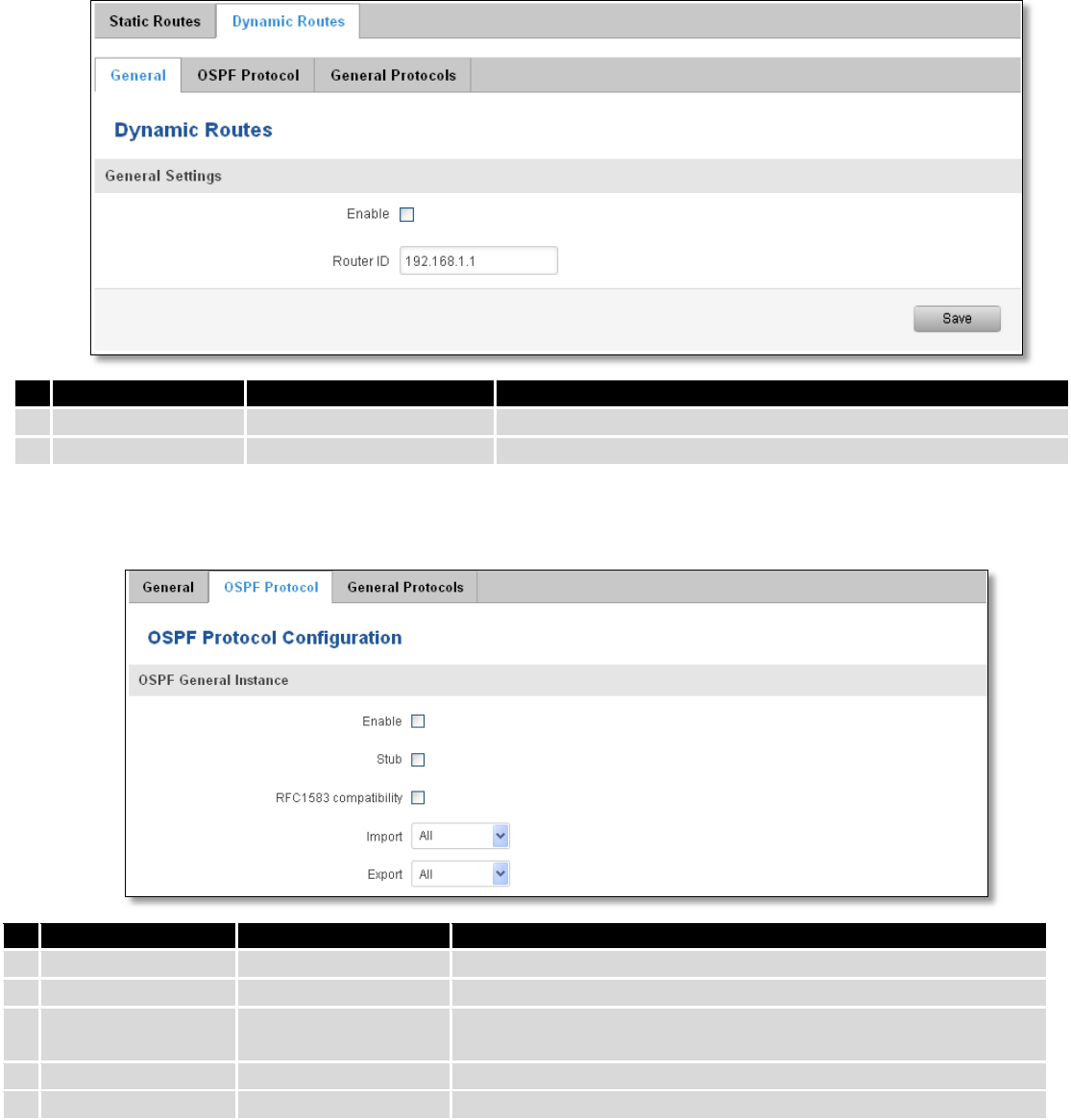
7.7.2 Dynamic Routes
7.7.2.1 General
Dynamic routes provide dynamic routing which enables router to select paths according to real-time logical
network layout changes.
82
7.7.2.2 OSPF Protocol
7.7.2.2.1 OSPF General Instance
Field name
Value
Explanation
1.
Enable
Enable/Disable
Enables OSPF protocol
2.
Stub
Enable/Disable
Enable/Disable stub
3.
RFC1583
compatibility
Enable/Disable
Enables OSPF compatibility with RFC1583 specification
4.
Import
All/None/custom
Set if the protocol must import routes
5.
Export
All/None/custom
Set if the protocol must export routes
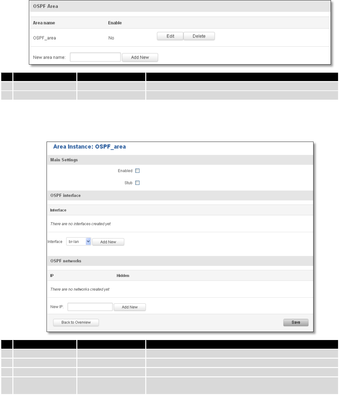
7.7.2.2.2 OSPF Area
The OSPF network can be divided into sub-domains called areas.
Field name
Value
Explanation
1.
Enable
Enable/Disable
Enable dynamic routes
2.
Router ID
192.168.1.1
Router’s ID
83
Field name
Value
Explanation
1.
Area name
OSPF_area
OSPF area’s name
2.
Enable
Yes/No
Enable/disable OSPF area
To see at specific configuration settings press “edit” button located in newly created OSPF area. A new page with
detailed configuration appears, as shown in the picture below.
Field name
Value
Explanation
1.
Enabled
Enable/Disable
Enable specific OSPF area
2.
Stub
Enable/Disable
Enable/disable stub
3.
Interface
br-lan
A interface that new instance will have
4.
New IP
Name of the new OSPF network configuration. Used for easer
configurations management purpose only
84
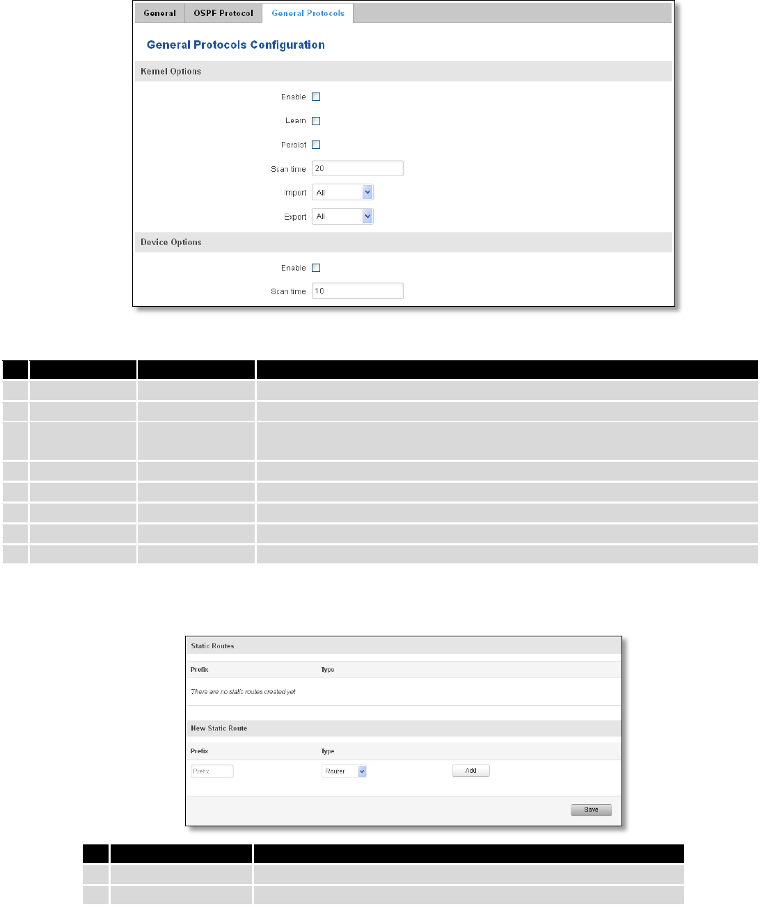
7.7.2.3 General Protocol
Field name
Value
Explanation
1.
Enable
Enable/Disable
Enable/Disable settings
2.
Learn
Enable/Disable
Enables routes learning
3.
Persist
Enable/Disable
If checked it allows to store routes. After a restart, routes will be still
configured
4.
Scan time
20
Time between scans
5.
Import
All
Set if the protocol must import routes
6.
Export
All
Set if the protocol must export routes
7.
Enable
Enable/Disable
If checked the protocol will not be configured
8.
Scan time
10
Time between scans
7.7.2.3.1 Static Routes
Field name
Explanation
1.
Prefix
Protocol prefix of incoming or outgoing packet
2.
Type
Protocol type of incoming or outgoing packet
85
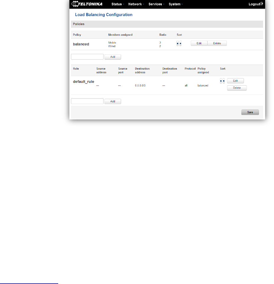
7.8 Load Balancing
Load balancing lets users divide traffic between different interfaces.
8 Remote monitoring and administration
RUT9XX supports multiple monitoring and administration possibilities. One can get routers information through
SMS or using RMS (Remote Management System). Furthermore, some system related parameters can be obtained using
MODBUSD or MQTT publisher services. How to use them are described in the 9.19 and 9.20 chapters respectively. The
main focus is on parameters, which change from time to time, like signal strength, operators name (it is quite common
to change of operator name in countries where inner roaming is used) or module temperature. Although it is also
possible to read more static values, like MAC address, router’s serial number and many others. The access to the
mentioned parameters is implemented in both MODBUSD and MQTT publisher applications. Apart from getting of
some parameters, MODBUSD also supports setting of some system related parameter, for example, change value of
digital output. Although it sounds frustrating, this functionality is sometimes useful and necessary.
Some applications, like MQTT publisher or RMS allows monitoring or administrating several routers from one
place. It is very useful functionality, when you have few routers and would like to change some parameter using single
application. RMS share some similarities with SSH (Secure Shell) and indeed, one of RMS feature is to allows SSH access
to remote router. There is no separate chapter about RMS in this manual, because the interface of RMS is very intuitive
and user friendly. You can access RMS by using your browser with supplied username and a password at
http://rms.teltonika.lt
By sending SMS to the router the user can execute some command, like reboot, switch wifi on or off and many
others. With each SMS the user need to specify router’s administrator password. This is done for authentication
purposes. The list of commands that may be executed through the SMS is limited. Full list of commands can be found on
Services-SMS Utilities of routers WEB page. More about router’s management using SMS can found in chapter 9.8.
Another interesting router monitoring solution is SNMP (Simple Network Management Protocol). By not going
into deep details about this protocol, it is another manner to monitor router parameters. It allows the user to check
current operator, modem model and other router parameters. Compared to other applications and services, only SNMP
have ability to inform the user about the occurrence of specific event (called trap) in the system. The main drawback of
this protocol is, that it does not allow to change anything. You can read more about SNMP in chapter 8.9.
86
Apart from services mentioned earlier, there is one service, which is used only for communication between router
and Android type device (phones, etc’). It is called json-rpc and allows to set or get various parameters of the system.
JSON-RPC can execute the same commands, like user through SSH. To sum up, this approach opens wide possibilities in
communication between router and Android. However, there is no separate topic about JSON-RPC in this manual,
because this type of communication is generally not for end-user use.
Each approach has its advantages and disadvantages. In some situations, maybe MQTT publisher works better
than MODBUSD, while in others, MODBUSD will be the better choice. The most versatile manner of system monitoring
and administration is through SSH. The SSH provides complete control of the router. The user can execute commands,
write shell scripts and do many other things. In such case, the user only needs application to connect router through
SSH. The most popular application used in Windows type operating systems is called Putty. If you try to connect to
router from Unix like operating system, you only need to execute ssh command with some arguments, like hostname
and username (in this case – root).
Sometimes the use of SSH is not necessary, so other more conservative services/applications are used. The
complete list of applications and services, which can be used for router administration and monitoring are given below.
It can be seen, that all applications, except MQTT publisher and SNMP supports setting/getting of some system related
parameter.
87
Application
Can obtain parameters
Can set parameters
1.
MQTT publisher
o
2.
MODBUS daemon
3.
SSH
4.
RMS
5.
SMS
6.
SNMP
o
7.
JSON-RPC
By summarizing, RUT9XX provides several solutions for router management. Each user can choose what solution
to use. If required functionality is not found in particular service, the user can combine several applications, for
example, use MQTT publisher along with SNMP. Finally, if user has special needs, he can write shell script and execute it
via SSH or use json-rpc.
9 Services
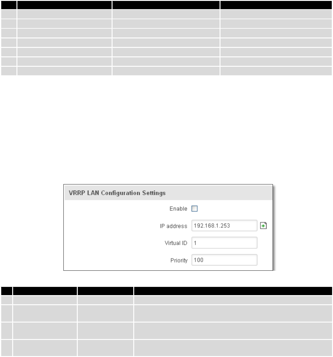
9.1 VRRP
9.1.1 VRRP LAN Configuration Settings
Field name
Sample
Explanation
1.
Enable
Enable/Disable
Enable VRRP (Virtual Router Redundancy Protocol) for LAN
2.
IP address
192.168.1.253
Virtual IP address for LAN's VRRP (Virtual Router Redundancy
Protocol) cluster
3.
Virtual ID
1
Routers with same IDs will be grouped in the same VRRP (Virtual
Router Redundancy Protocol) cluster, range [1-255]
4.
Priority
100
Router with highest priority value on the same VRRP (Virtual Router
Redundancy Protocol) cluster will act as a master, range [1-255]
88
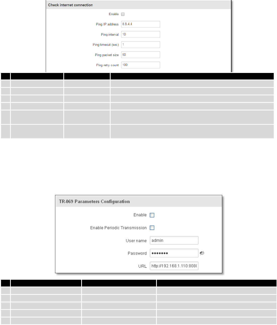
9.1.2 Check Internet connection
Field name
Sample
Explanation
1.
Enable
Enable/Disable
Enable WAN's connection monitoring
2.
Ping IP address
8.8.4.4
A host to send ICMP (Internet Control Message Protocol) packets to
3.
Ping interval
10
Time interval in seconds between two Pings
4.
Ping timeout (sec)
1
Response timeout value, interval [1 - 9999]
5.
Ping packet size
50
ICMP (Internet Control Message Protocol) packet's size, interval [0 -
1000]
6.
Ping retry count
100
Failed Ping attempt’s count before determining that connection is
lost, interval [1 – 9999]
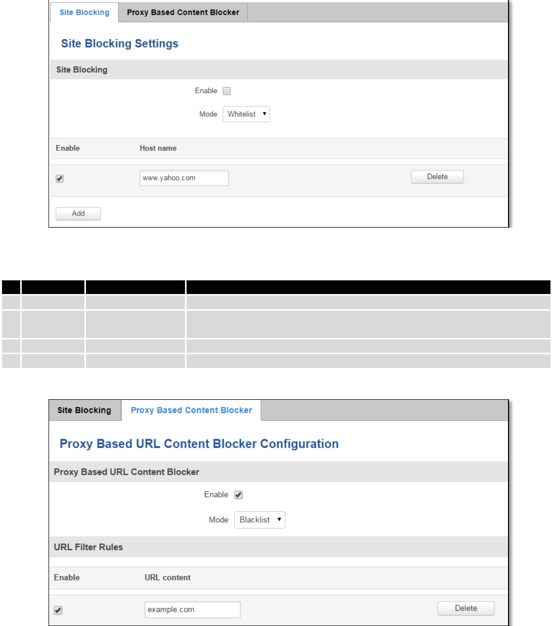
9.2 TR-069
TR-069 is a standard developed for automatic configuration and management of remote devices by Auto
Configuration Servers (ACS).
9.2.1 TR-069 Parameters Configuration
Field name
Sample
Explanation
1.
Enable
Enable/Disable
Enable TR-069 client
2.
Enable Periodic Transmission
Enable / Disable
Enable periodic transmissions of data to server
3.
User name
admin
User name for authentication on TR-069 server
4.
Password
*******
Password for authentication on TR-069 server
5.
URL
http://192.168.1.110:8080
TR-069 server URL address
89
9.3 Web filter
9.3.1 Site blocking
Field name
Sample
Explanation
1.
Enable
Enable/Disable
Enable host name based websites blocking
2.
Mode
Whitelist/Blacklist
Whitelist - allow every site on the list and block everything else. Blacklist -
block every site on the list and allow everything else.
3.
Enable
Enable/Disable
Check to enable site blocking
4.
Host name
www.yahoo.com
Block/allow site with this hostname
9.3.2 Proxy Based Content Blocker
90
Field name
Sample
Explanation
1.
Enable
Enable/Disable
Enable proxy server based URL content blocking. Works with HTTP
protocol only
2.
Mode
Whitelist/Blacklist
Whitelist - allow every part of URL on the list and block everything
else. Blacklist - block every part of URL on the list and allow everything
else
3.
URL
content
example.com
Block/allow any URL containing this string. Example.com, example.*,
*.example.com
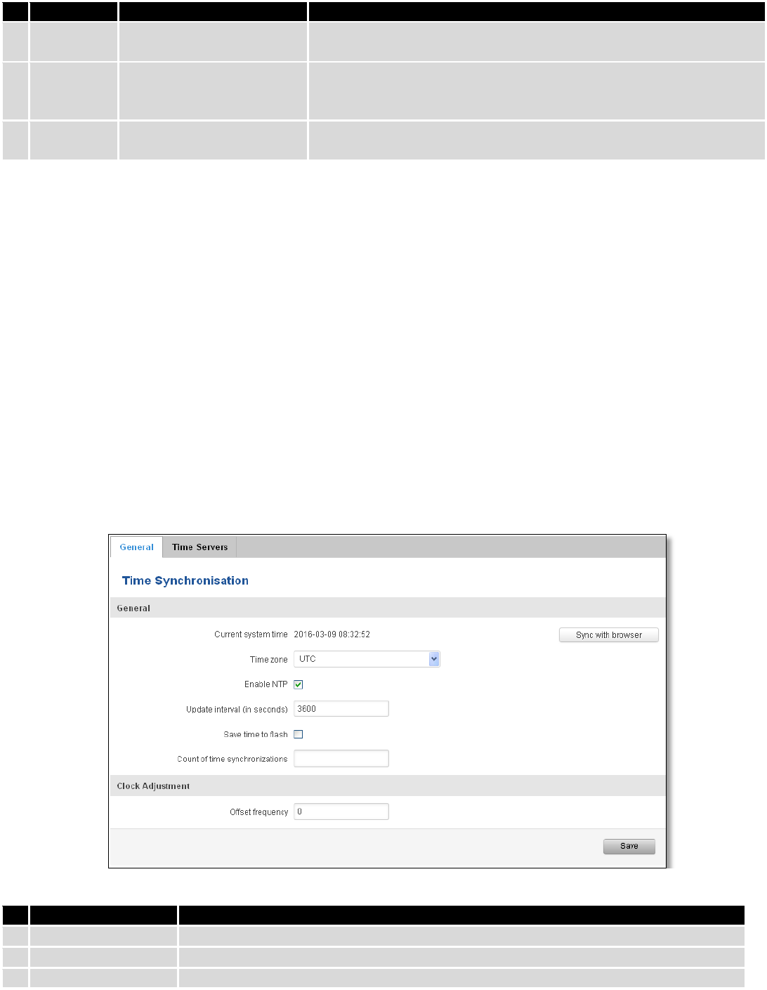
9.4 NTP
NTP configuration lets you setup and synchronize routers time.
Field name
Description
1.
Current System time
Local time of router.
2.
Time zone
Time zone of your country.
3.
Enable NTP
Enable system’s time synchronization with time server using NTP (Network Time
91
Protocol)
4.
Update interval
How often router updates systems time
5.
Save time to flash
Save last synchronized time to flash memory
6.
Count of time
synchronizations
Total amount of times that router will do the synchronization. Note: If left blank - the
count will be infinite
7.
Offset frequency
Adjust the minor drift of the clock so that it will be more accurate
Note, that under Time Servers at least one server has to be present, otherwise NTP will not serve its purposes.
9.5 VPN
9.5.1 OpenVPN
VPN (Virtual Private Network) is a method for secure data transfer through unsafe public network. This section
explains how to configure OpenVPN, which is implementation of VPN supported by the RUT9 router.
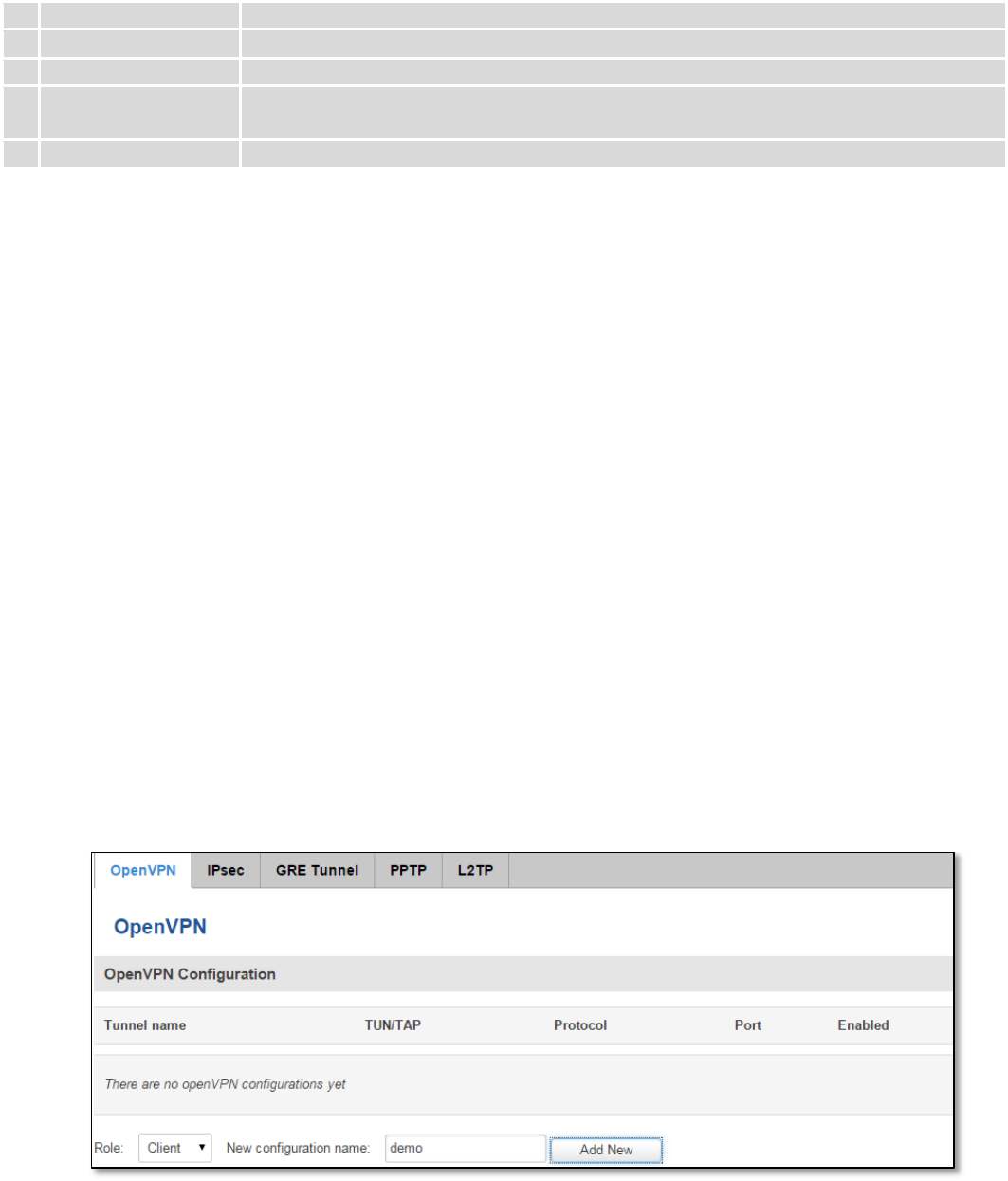
A picture below demonstrates default OpenVPN configurations list, which is empty, so you have to define a new
configuration to establish any sort of OpenVPN connection. To create it, enter desired configuration name in “New
configuration name” field, select device role from “Role” drop down list. For example, to create an OpenVPN client with
configuration name demo, select client role, name it “demo” and press “Add New” button as shown in the following
picture.
92
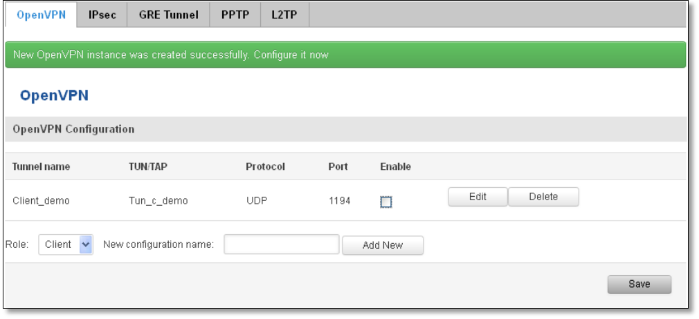
To see at specific configuration settings press “edit” button located in newly created configuration entry. A new
page with detailed configuration appears, as shown in the picture below (TLS client example).
93
There can be multiple server/client instances.
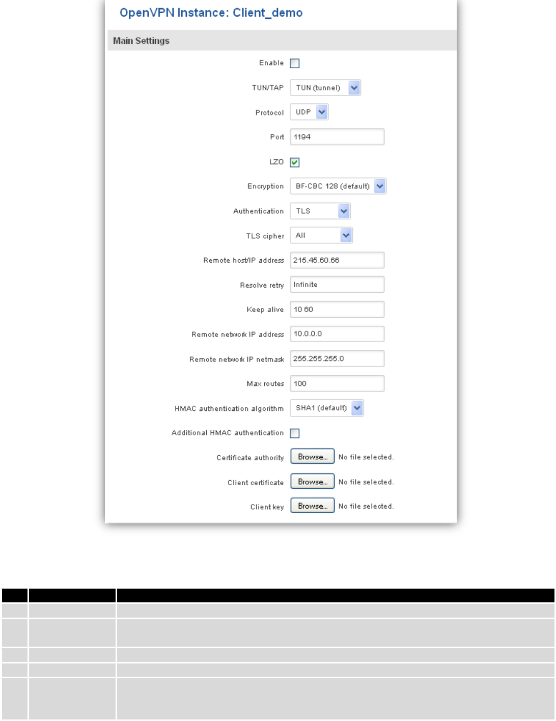
You can set custom settings here according to your VPN needs. Below is summary of parameters available to set:
Field name
Explanation
1.
Enabled
Switches configuration on and off. This must be selected to make configuration active.
2.
TUN/TAP
Selects virtual VPN interface type. TUN is most often used in typical IP-level VPN connections,
however, TAP is required to some Ethernet bridging configurations.
3.
Protocol
Defines a transport protocol used by connection. You can choose here between TCP and UDP.
4.
Port
Defines TCP or UDP port number (make sure, that this port allowed by firewall).
5.
LZO
This setting enables LZO compression. With LZO compression, your VPN connection will
generate less network traffic; however, this means higher router CPU loads. Use it carefully
with high rate traffic or low CPU resources.

94
6.
Encryption
Selects Packet encryption algorithm.
7.
Authentication
Sets authentication mode, used to secure data sessions. Two possibilities you have here:
“Static key” means, that OpenVPN client and server will use the same secret key, which must
be uploaded to the router using “Static pre-shared key” option. “TLS” authentication mode
uses X.509 type certificates. Depending on your selected OpenVPN mode (client or server)
you have to upload these certificates to the router:
For client: Certificate Authority (CA), Client certificate, Client key.
For server: Certificate Authority (CA), Server certificate, Server key and Diffie-Hellman (DH)
certificate used to key exchange through unsafe data networks.
All mention certificates can be generated using OpenVPN or Open SSL utilities on any type
host machine. Certificate generation and theory is out of scope of this user manual.
8.
TLS cipher
Packet encryption algorithm (cipher)
9.
Remote host/IP
address
IP address of OpenVPN server (applicable only for client configuration).
10.
Resolve Retry
Sets time in seconds to try resolving server hostname periodically in case of first resolve
failure before generating service exception.
11.
Keep alive
Defines two time intervals: one is used to periodically send ICMP request to OpenVPN server,
and another one defines a time window, which is used to restart OpenVPN service, if no ICPM
request is received during the window time slice. Example Keep Alive “10 60”
12.
Remote network
IP address
IP address of remote network, an actual LAN network behind another VPN endpoint.
13.
Remote network
IP netmask
Subnet mask of remote network, an actual LAN network behind another VPN endpoint.
14.
Max routes
Allow a maximum number of routes to be pulled from an OpenVPN server
15.
HMAC
authentication
algorithm
Sets HMAC authentication algorithm
16.
Additional
HMAC
authentication
Add an additional layer of HMAC authentication on top of the TLS control channel to protect
against DoS attacks
17.
Certificate
authority
Certificate authority is an entity that issues digital certificates. A digital certificate certifies the
ownership of a public key by the named subject of the certificate.
18.
Client certificate
Client certificate is a type of digital certificate that is used by client systems to make
authenticated requests to a remote server. Client certificates play a key role in many mutual
authentication designs, providing strong assurances of a requester's identity.
19.
Client key
Authenticating the client to the server and establishing precisely who they are
After setting any of these parameters press “Save” button. Some of selected parameters will be shown in the
configuration list table. You should also be aware of the fact that router will launch separate OpenVPN service for every
configuration entry (if it is defined as active, of course) so the router has ability to act as server and client at the same
time.
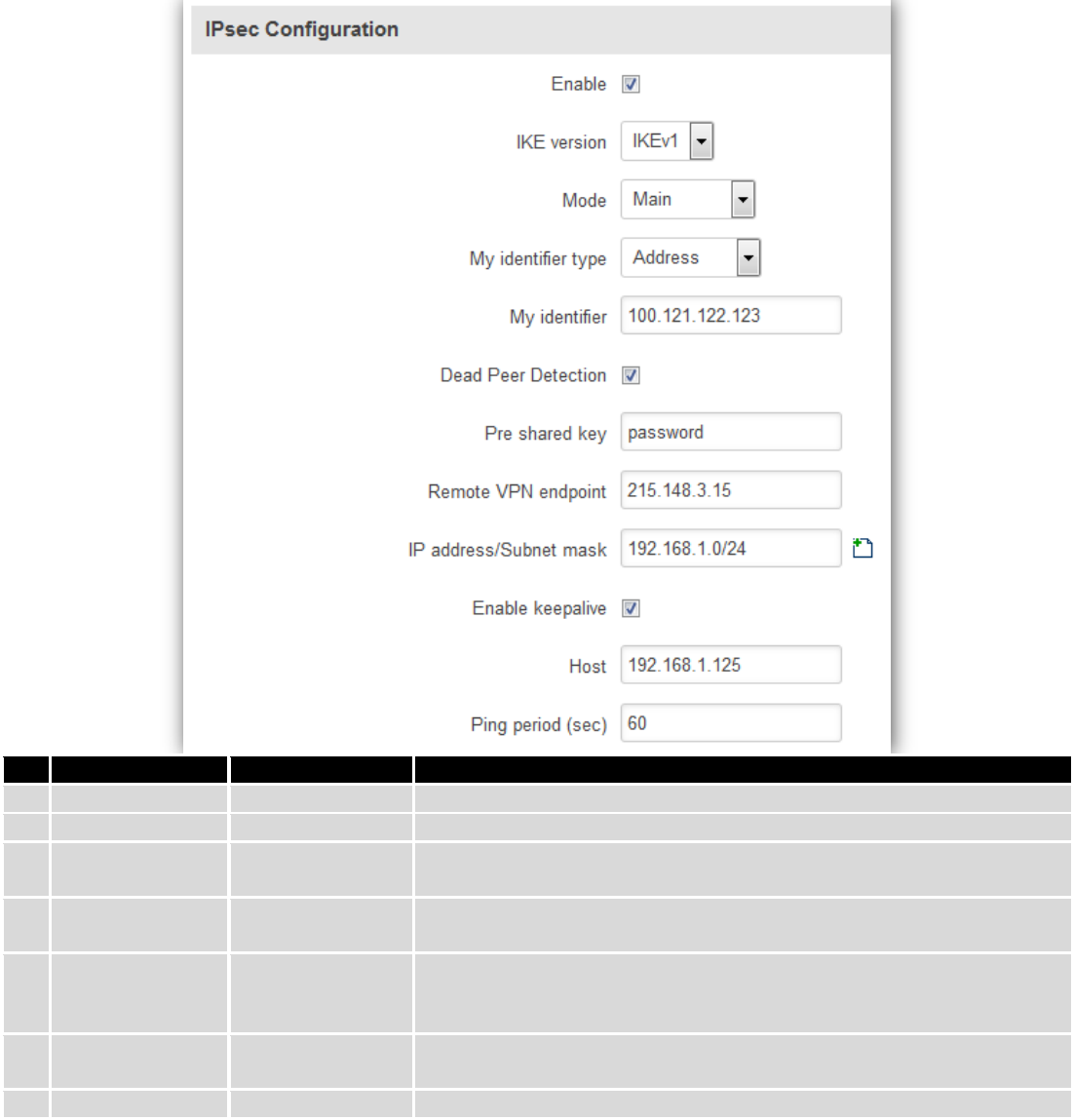
9.5.2 IPSec
The IPsec protocol client enables the router to establish a secure connection to an IPsec peer via the Internet.
IPsec is supported in two modes - transport and tunnel. Transport mode creates secure point to point channel between
two hosts. Tunnel mode can be used to build a secure connection between two remote LANs serving as a VPN solution.
95
IPsec system maintains two databases: Security Policy Database (SPD) which defines whether to apply IPsec to a
packet or not and specify which/how IPsec-SA is applied and Security Association Database (SAD), which contain Key of
each IPsec-SA.
The establishment of the Security Association (IPsec-SA) between two peers is needed for IPsec communication. It
can be done by using manual or automated configuration.
Note: router starts establishing tunnel when data from router to remote site over tunnel is sent. For automatic
tunnel establishment used tunnel Keep Alive feature.
Field name
Value
Explanation
1.
Enable
Enabled/Disabled
Check box to enable IPSec.
2.
IKE version
IKEv1 or IKEv2
Method of key exchange
3.
Mode
“Main” or
“Aggressive”
ISAKMP (Internet Security Association and Key Management Protocol)
phase 1 exchange mode
4.
My identifier type
Address, FQDN,
User FQDN
Choose one accordingly to your IPSec configuration
5.
My identifier
Set the device identifier for IPSec tunnel.
In case RUT has Private IP, its identifier should be its own LAN network
address. In this way, the Road Warrior approach is possible.
6.
Dead Peer
Detection
Enabled/Disabled
The values clear, hold and restart all active DPD
7.
Pre shared key
A shared password to authenticate between the peer
96
8.
Remote VPN
endpoint
Domain name or IP address. Leave empty or any
9.
IP
address/Subnet
mask
Remote network secure group IP address and mask used to determine to
what subnet an IP address belongs to. Range [0-32]. IP should differ from
device LAN IP
10.
Enable keep alive
Enabled/Disabled
Enable tunnel keep alive function
11.
Host
A host address to which ICMP (Internet Control Message Protocol) echo
requests will be send
12.
Ping period (sec)
Send ICMP echo request every x seconds. Range [0-999999]
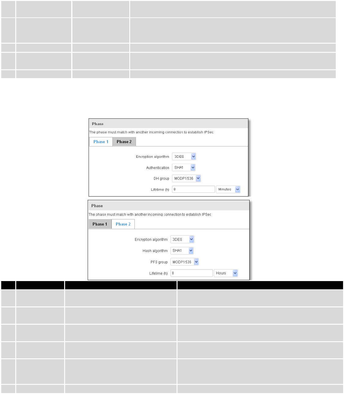
Phase 1 and Phase 2 must be configured accordingly to the IPSec server configuration, thus algorithms,
authentication and lifetimes of each phase must be identical.
Field name
Value
Explanation
1.
Encryption
algorithm
DES, 3DES, AES 128, AES 192, AES256
The encryption algorithm must match with another
incoming connection to establish IPSec
2.
Authentication
MD5, SHA1, SHA256, SHA384, SHA512
The authentication algorithm must match with another
incoming connection to establish IPSec
3.
Hash algorthm
MD5, SHA1, SHA256, SHA384, SHA512
The hash algorithm must match with another incoming
connection to establish IPSec
4.
DH group
MODP768, MODP1024, MODP1536,
MODP2048, MODP3072, MODP4096
The DH (Diffie-Helman) group must with another
incoming connection to establish IPSec
4.
PFS group
MODP768, MODP1024, MODP1536,
MODP2048, MODP3072, MODP4096,
No PFS
The PFS (Perfect Forward Secrecy) group must match with
another incoming connection to establish IPSec
5.
Lifetime
Hours, Minutes, Seconds
The time duration for phase
97
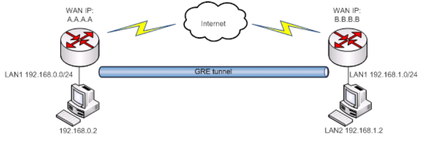
9.5.3 GRE Tunnel
GRE (Generic Routing Encapsulation RFC2784) is a solution for tunneling RFC1812 private address-space traffic
over an intermediate TCP/IP network such as the Internet. GRE tunneling does not use encryption it simply encapsulates
data and sends it over the WAN.
In the example network diagram two distant networks LAN1 and LAN2 are connected.
To create GRE tunnel the user must know the following parameters:
1. Source and destination IP addresses.
2. Tunnel local IP address
3. Distant network IP address and Subnet mask.
98
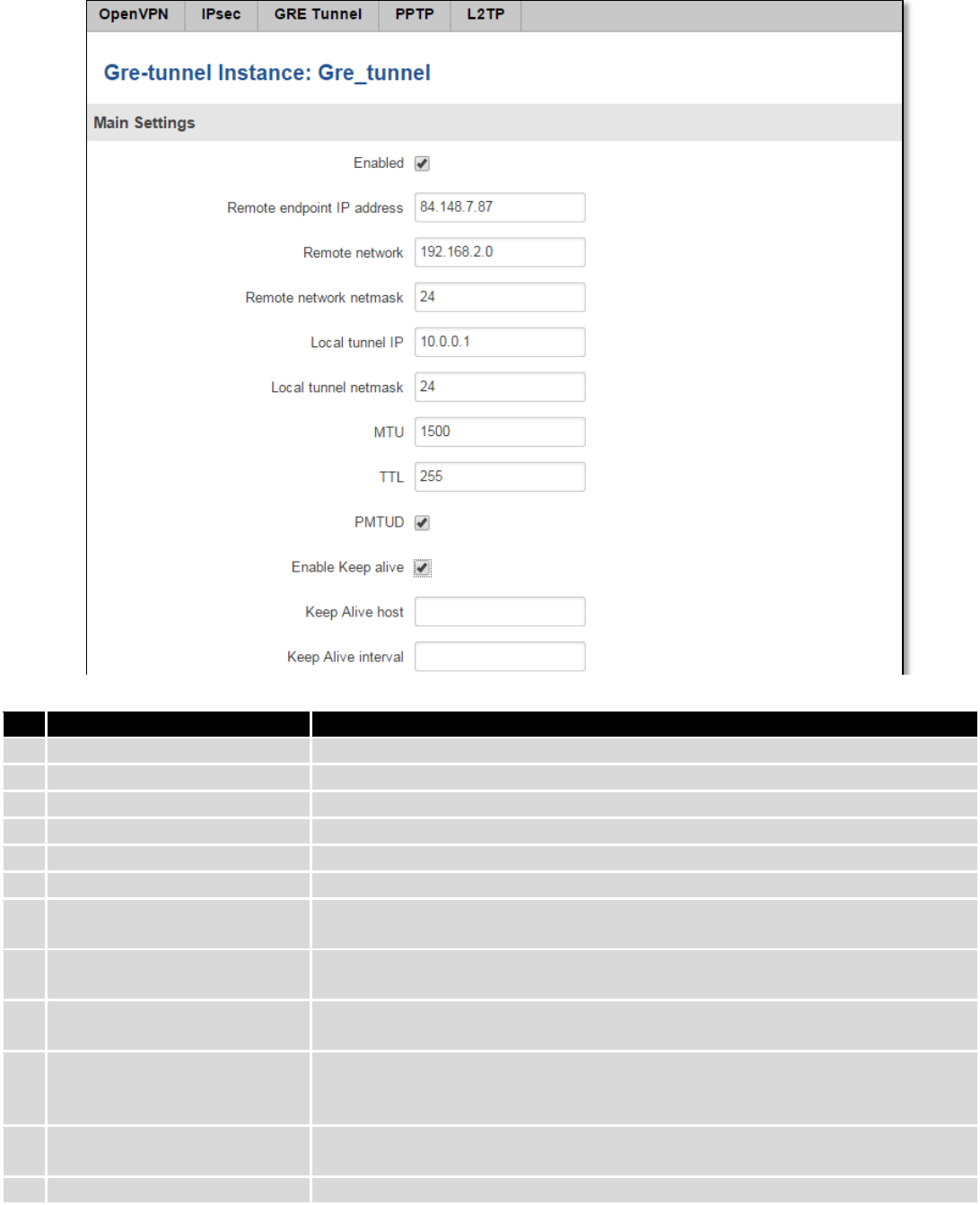
Field name
Explanation
1.
Enabled
Check the box to enable the GRE Tunnel function.
2.
Remote endpoint IP address
Specify remote WAN IP address.
3.
Remote network
IP address of LAN network on the remote device.
4.
Remote network netmask
Network of LAN network on the remote device. Range [0-32].
5.
Local tunnel IP
Local virtual IP address. Cannot be in the same subnet as LAN network.
6.
Local tunnel netmask
Network of local virtual IP address. Range [0-32]
7.
MTU
Specify the maximum transmission unit (MTU) of a communications protocol of
a layer in bytes.
8.
TTL
Specify the fixed time-to-live (TTL) value on tunneled packets [0-255]. The 0 is a
special value meaning that packets inherit the TTL value.
9.
PMTUD
Check the box to enable the Path Maximum Transmission Unit Discovery
(PMTUD) status on this tunnel.
10.
Enable Keep alive
It gives the ability for one side to originate and receive keep alive packets to and
from a remote router even if the remote router does not support GRE keep
alive.
11.
Keep Alive host
Keep Alive host IP address. Preferably IP address which belongs to the LAN
network on the remote device.
12.
Keep Alive interval
Time interval for Keep Alive. Range [0 - 255].
99
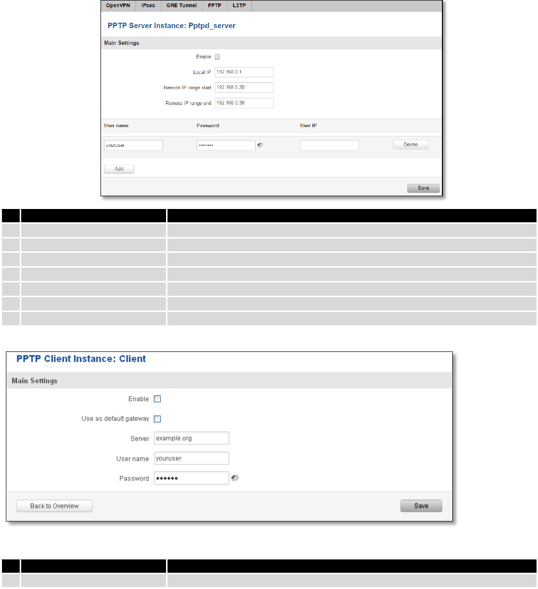
9.5.4 PPTP
Point-to-Point Tunneling Protocol (PPTP) is a protocol (set of communication rules) that allows corporations to
extend their own corporate network through private "tunnels" over the public Internet. Effectively, a corporation uses a
wide-area network as a single large local area network. A company no longer needs to lease its own lines for wide-area
communication but can securely use the public networks. This kind of interconnection is known as a virtual private
network (VPN).
Field name
Explanation
1.
Enable
Check the box to enable the PPTP function.
2.
Local IP
IP Address of this device (RUT)
3.
Remote IP range begin
IP address leases beginning
4.
Remote IP range end
IP address leases end
5.
Username
Username to connect to PPTP (this) server
6.
Password
Password to connect to PPTP server
7.
User IP
Users IP address
Field name
Explanation
1.
Enable
Enable current configuration
100
2.
Use as default gateway
Use this PPTP instance as default gateway
3.
Server
The server IP address or hostname
4.
Username
The user name for authorization with the server
5.
Password
The password for authorization with the server
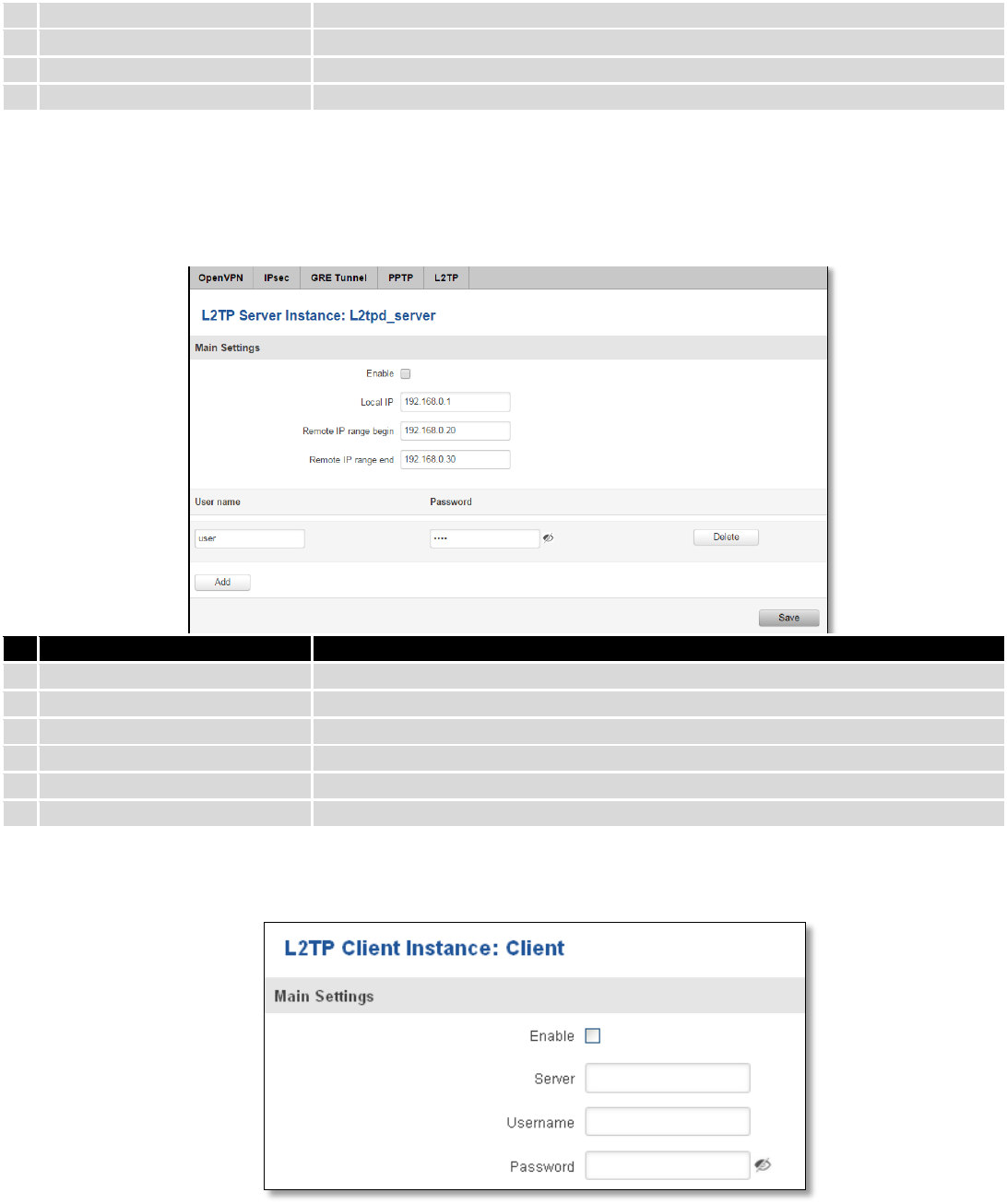
9.5.5 L2TP
Allows setting up a L2TP server or client. Below is L2TP server configuration example.
Field name
Explanation
1.
Enable
Check the box to enable the L2TP Tunnel function.
2.
Local IP
IP Address of this device (RUT)
3.
Remote IP range begin
IP address leases beginning
4.
Remote IP range end
IP address leases end
5.
Username
Username to connect to L2TP (this) server
6.
Password
Password to connect to L2TP server
Client configuration is even simpler, which requires only Servers IP, Username and Password.
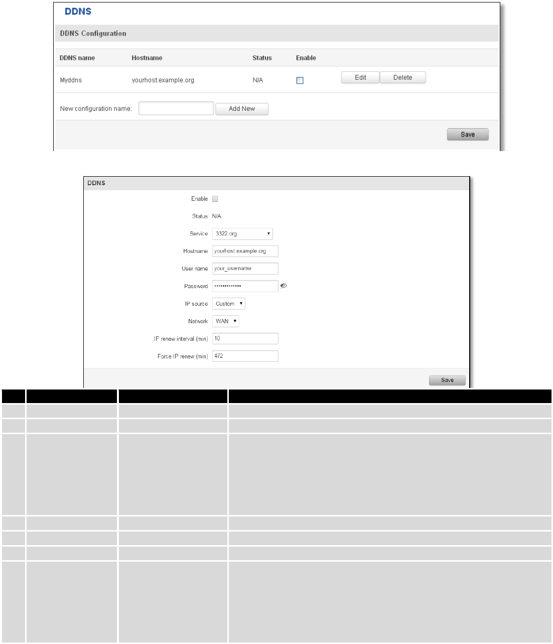
9.6 Dynamic DNS
Dynamic DNS (DDNS) is a domain name service allowing to link dynamic IP addresses to static hostname.
To start using this feature firstly you should register to DDNS service provider (example list is given in description).
101
You are provided with add/delete buttons to manage and use different DDNS configurations at the same time!
You can configure many different DDNS Hostnames in the main DDNS Configuration section.
To edit your selected configuration, hit Edit.
Field name
Value
Explanation
1.
Enable
Enable/Disable
Enables current DDNS configuration.
2.
Status
Timestamp of the last IP check or update.
3.
Service
1. dydns.org
2. 3322.org
3. no-ip.com
4. easydns.com
5. zoneedit.com
Your dynamic DNS service provider selected from the list.
In case your DDNS provider is not present from the ones provided,
please feel free to use "custom" and add hostname of the update
URL.
4.
Hostname
yourhost.example.org
Domain name which will be linked with dynamic IP address.
5.
Username
your_username
Name of the user account.
6.
Password
your_password
Password of the user account.
7.
IP Source
Public
Private
Custom
This option allows you to select specific RUT interface, and then send
the IP address of that interface to DDNS server. So if, for example,
your RUT has Private IP (i.e. 10.140.56.57) on its WAN (3G interface),
then you can send this exact IP to DDNS server by selecting "Private",
or by selecting "Custom" and "WAN" interface. The DDNS server will
then resolve hostname queries to this specific IP.
102
8.
Network
WAN
Source network
9.
IP renew interval
(min)
10 (minutes)
Time interval (in minutes) to check if the IP address of the device
have changed.
10.
Force IP renew
472 (minutes)
Time interval (in minutes) to force IP address renew.
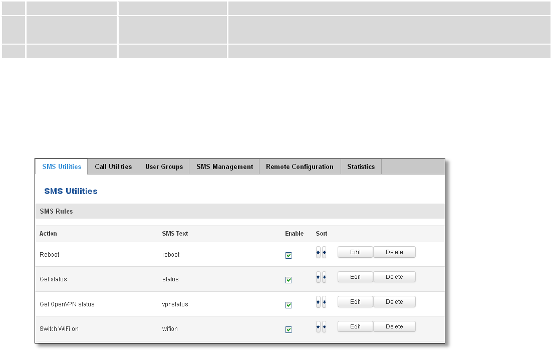
9.7 SMS Utilities
RUT950 has extensive amount of various SMS Utilities. These are subdivided into 6 sections: SMS Utilities, Call
Utilities, User Groups, SMS Management, Remote Configuration and Statistics.
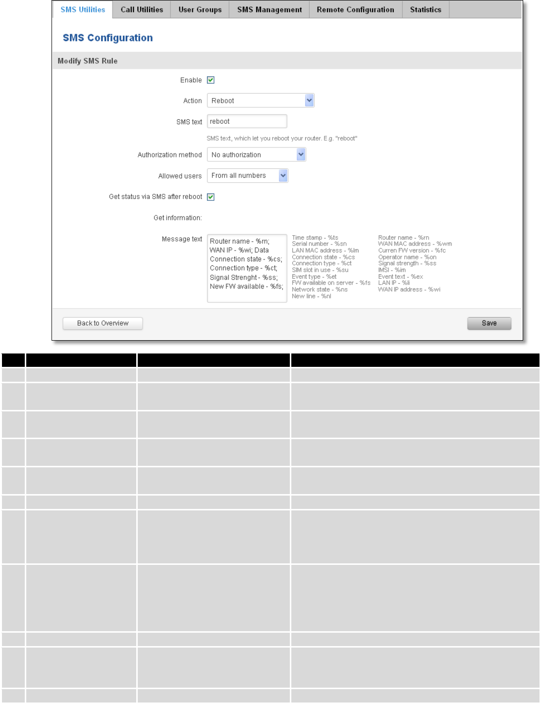
9.7.1 SMS Utilities
All configuration options are listed below:
- Reboot
- Get status
- Get OpenVPN status
- Switch WiFi on/off
- Switch mobile data on/off
- Change mobile data settings
- Get list of profiles
- Change profile
- Manage OpenVPN
- SSh access control
- Web access control
- Restore to default
- Force SIM switch
- FW upgrade from server
- Config update from server
- Switch monitoring on/off
You can choose your SMS Keyword (text to be sent) and authorized phone number in the main menu. You can
edit each created rule by hitting Edit button.
103
Field name
Explanation
Notes
1.
Reboot
Enable
This check box will enable and
disable SMS reboot function.
Allows router restart via SMS.
Action
The action to be performed
when this rule is met.
SMS text
SMS text which will reboot
router.
SMS text can contain letters, numbers, spaces and
special symbols. Capital letters also matters.
Authorization method
What kind of authorization to
use for SIM management.
No authorization, by serial or by router admin
password.
Allowed users
Whitelist of allow users
From all numbers, from group or from single number.
Get status via SMS
after reboot
Check this to recieve
connection status via SMS after
a reboot.
If you select this box, router will send status once it
has rebooted and is operational again.
This is both separate SMS Rule and an option under
SMS Reboot rule.
Message text
Which status information
should be included in SMS:
Data state, Operator,
Connection type, Signal
Strength, Connection State, IP
You can select which status elements to display.
2.
Get status
Enable
Check this to receive
connection status via SMS.
Allows to get router‘s status via SMS. This is both
separate SMS Rule and an option under SMS Reboot
rule.
Action
The action to be performed

104
when this rule is met.
Enable SMS Status
This check box will enable and
disable SMS status function.
SMS status is disabled by default.
SMS text
SMS text which will send
routers status.
SMS text can contain letters, numbers, spaces and
special symbols. Capital letters also matters.
Authorization method
What kind of authorization to
use for SIM management.
No authorization, by serial or by router admin
password.
Allowed users
Whitelist of allow users
From all numbers, from group or from single number.
Message text
Which status information
should be included in SMS:
Data state, Operator,
Connection type, Signal
Strength, Connection State, IP
You can select which status elements to display.
3.
Get OpenVPN status
Enable
This check box will enable and
disable this function.
Allows to get OpenVPN‘s status via SMS.
Action
The action to be performed
when this rule is met.
SMS text
SMS text which will send
OpenVPN status.
SMS text can contain letters, numbers, spaces and
special symbols. Capital letters also matters.
Authorization method
What kind of authorization to
use for SIM management.
No authorization, by serial or by router admin
password.
Allowed users
Whitelist of allow users
From all numbers, from group or from single number.
4.
Switch WiFi On/Off
Enable
This check box will enable and
disable this function.
Allows Wi-Fi control via SMS.
Action
The action to be performed
when this rule is met.
Turn WiFi ON or OFF.
SMS text
SMS text which will turn Wi-Fi
ON/OFF.
SMS text can contain letters, numbers, spaces and
special symbols. Capital letters also matters.
Authorization method
What kind of authorization to
use for SIM management.
No authorization, by serial or by router admin
password.
Allowed users
Whitelist of allow users
From all numbers, from group or from single number.
Write to config
Permanently saves Wi-Fi state.
With this setting enabled, router will keep Wi-Fi state
even after reboot.
If it is not selected, router will revert Wi-Fi state after
reboot.
5.
Switch mobile data
on/off
Enable
This check box will enable and
disable this function.
Allows mobile control via SMS.
Action
The action to be performed
when this rule is met.
Turn mobile ON or OFF.
SMS text
SMS text which will turn mobile
data ON/OFF.
SMS text can contain letters, numbers, spaces and
special symbols. Capital letters also matters.
Authorization method
What kind of authorization to
use for SIM management.
No authorization, by serial or by router admin
password.
Allowed users
Whitelist of allow users
From all numbers, from group or from single number.
Write to config
Permanently saves mobile
network state.
With this setting enabled, router will keep mobile
state even after reboot.

105
If it is not selected, router will revert mobile state
after reboot.
6.
Manage OpenVPN
Enable
This check box will enable and
disable this function.
Allows OpenVPN control via SMS.
Action
The action to be performed
when this rule is met.
Turn OpenVPN ON or OFF.
SMS text
Keyword which will turn
OpenVPN ON/OFF.
SMS text can contain letters, numbers, spaces and
special symbols. Capital letters also matters.
After Keyword you have to write OpenVPN name.
Authorization method
What kind of authorization to
use for SIM management.
No authorization, by serial or by router admin
password.
Allowed users
Whitelist of allow users
From all numbers, from group or from single number.
7.
Change mobile data
settings
Enable
This check box will enable and
disable this function.
Allows to change mobile settings via SMS.
Action
The action to be performed
when this rule is met.
SMS text
Key word that will precede
actual configuration
parameters.
SMS text can contain letters, numbers, spaces and
special symbols. Capital letters also matters.
Authorization method
What kind of authorization to
use for SIM management.
No authorization, by serial or by router admin
password.
Allowed users
Whitelist of allow users
From all numbers, from group or from single number.
Mobile Settings via SMS parameters:
Parameter
Value(s)
Explanation
1.
apn=
e.g. internet.gprs
Sets APN. i.e: apn=internet.gprs
2.
dialnumber=
e.g. *99***1#
Sets dial number
3.
auth_mode=
none
pap
chap
Sets authentication mode
4.
service=
Auto
4gpreferred
4gonly
3gpreferred
3gonly
2gpreferred
2gonly
You can add as many phone numbers as you need.
Dropdown list with additional rows will show up if you
click on “add” icon at the end of phone number row.
5.
username=
user
Used only if PAP or CHAP authorization is selected
6.
password=
user
Used only if PAP or CHAP authorization is selected
All Mobile settings can be changed in one SMS. Between each <parameter=value> pair a space symbol is
necessary.
Example: cellular apn=internet.gprs dialnumber=*99***1#auth_mode=pap service=3gonly username=user
password=user
Important Notes:

106
3G settings must be configured correctly. If SIM card has PIN number you must enter it at “Network” > “3G”
settings. Otherwise SMS reboot function will not work.
Sender phone number must contain country code. You can check sender phone number format by reading
the details of old SMS text massages you receiving usually.
Field name
Explanation
Notes
8.
Get list of profiles
Enable
This check box will enable and
disable this function.
Allows to get list of profiles via SMS.
Action
The action to be performed
when this rule is met.
SMS text
SMS text which will send list of
profiles.
SMS text can contain letters, numbers, spaces and
special symbols. Capital letters also matters.
Authorization method
What kind of authorization to
use for SIM management.
No authorization, by serial or by router admin
password.
Allowed users
Whitelist of allow users
From all numbers, from group or from single number.
9.
Change profile
Enable
This check box will enable and
disable this function.
Allows profile change via SMS.
Action
The action to be performed
when this rule is met.
SMS text
Keyword which will change
active profile.
SMS text can contain letters, numbers, spaces and
special symbols. Capital letters also matters.
After Keyword you have to write profile name.
Authorization method
What kind of authorization to
use for SIM management.
No authorization, by serial or by router admin
password.
Allowed users
Whitelist of allow users
From all numbers, from group or from single number.
10.
SSH access Control
Enable
This check box will enable and
disable this function.
Allows SSH access control via SMS.
Action
The action to be performed
when this rule is met.
SMS text
SMS text which will turn SSH
access ON/OFF.
SMS text can contain letters, numbers, spaces and
special symbols. Capital letters also matters.
Authorization method
What kind of authorization to
use for SIM management.
No authorization, by serial or by router admin
password.
Allowed users
Whitelist of allow users
From all numbers, from group or from single number.
Enable SSH access
Enable this to reach router via
SSH from LAN (Local Area
Network).
If this box is selected, SMS will enable SSH access from
LAN. If this box is not selected, SMS will disable SSH
access from LAN.
Enable remote SSH
access
Enable this to reach router via
SSH from WAN (Wide Area
Network).
If this box is selected, SMS will enable SSH access from
WAN. If this box is not selected, SMS will disable SSH
access from WAN.
11.
Web access Control
Enable
This check box will enable and
disable this function.
Allows Web access control via SMS.
Action
The action to be performed
when this rule is met.
SMS text
SMS text which will turn Web
SMS text can contain letters, numbers, spaces and

107
access ON/OFF.
special symbols. Capital letters also matters.
Authorization method
What kind of authorization to
use for SIM management.
No authorization, by serial or by router admin
password.
Allowed users
Whitelist of allow users
From all numbers, from group or from single number.
Enable HTTP access
Enable this to reach router via
HTTP from LAN (Local Area
Network).
If this box is selected, SMS will enable HTTP access
from LAN. If this box is not selected, SMS will disable
HTTP access from LAN.
Enable remote HTTP
access
Enable this to reach router via
HTTP from WAN (Wide Area
Network).
If this box is selected, SMS will enable HTTP access
from WAN. If this box is not selected, SMS will disable
HTTP access from WAN.
Enable remote HTTPS
access
Enable this to reach router via
HTTPS from WAN (Wide Area
Network).
If this box is selected, SMS will enable HTTPS access
from WAN. If this box is not selected, SMS will disable
HTTPS access from WAN.
12.
Restore to default
Enable
This check box will enable and
disable this function.
Allows to restore router to default settings via SMS.
Action
The action to be performed
when this rule is met.
Router will reboot after this rule is executed.
SMS text
SMS text which will turn Wi-Fi
ON/OFF.
SMS text can contain letters, numbers, spaces and
special symbols. Capital letters also matters.
Authorization method
What kind of authorization to
use for SIM management.
No authorization, by serial or by router admin
password.
Allowed users
Whitelist of allow users
From all numbers, from group or from single number.
13.
Force switch SIM
Enable
This check box will enable and
disable this function.
Allows SIM switch via SMS.
Action
The action to be performed
when this rule is met.
SMS text
SMS text which will change
active SIM card to another one.
SMS text can contain letters, numbers, spaces and
special symbols. Capital letters also matters.
Authorization method
What kind of authorization to
use for SIM management.
No authorization, by serial or by router admin
password.
Allowed users
Whitelist of allow users
From all numbers, from group or from single number.
Sender phone number
Phone number of person who
can receive router status via
SMS message.
You can add as many phone numbers as you need.
Dropdown list with additional rows will show up if you
click on “add” icon at the end of phone number row.
14.
Force FW upgrade
from server
Enable
This check box will enable and
disable this function.
Allows to upgrade router‘s FW via SMS.
Action
The action to be performed
when this rule is met.
Router will reboot after this rule is executed.
SMS text
SMS text which will force router
to upgrade firmware from
server.
SMS text can contain letters, numbers, spaces and
special symbols. Capital letters also matters.
Authorization method
What kind of authorization to
use for SIM management.
No authorization, by serial or by router admin
password.
Allowed users
Whitelist of allow users
From all numbers, from group or from single number.

108
15.
Force Config update
from server
Enable
This check box will enable and
disable this function.
Allows to upgrade router‘s Config via SMS.
Action
The action to be performed
when this rule is met.
Router will reboot after this rule is executed.
SMS text
SMS text which will force router
to upgrade configuration from
server.
SMS text can contain letters, numbers, spaces and
special symbols. Capital letters also matters.
Authorization method
What kind of authorization to
use for SIM management.
No authorization, by serial or by router admin
password.
Allowed users
Whitelist of allow users
From all numbers, from group or from single number.
16.
Switch monitoring
on/off
Enable
This check box will enable and
disable this function.
Allows monitoring control via SMS.
Action
The action to be performed
when this rule is met.
Turn monitoring ON or OFF.
SMS text
SMS text which will turn
monitoring ON/OFF
SMS text can contain letters, numbers, spaces and
special symbols. Capital letters also matters.
Authorization method
What kind of authorization to
use for SIM management.
By serial or by router admin password.
Allowed users
Whitelist of allow users
From all uers, from group or from single number.
Important Notes:
3G settings must be configured correctly. If SIM card has PIN number you must enter it at “Network” > “3G”
settings. Otherwise SMS reboot function will not work.
Sender phone number must contain country code. You can check sender phone number format by reading
the details of old SMS text massages you receiving usually.
9.7.2 Call Utilities
Allow users to call to the router in order to perform one of the actions: Reboot, Get Status, turn Wi-Fi ON/OFF,
turn Mobile data ON/OFF. Only thing that is needed is to call routers SIM card number from allowed phone (user) and
RUT9 will perform all actions that are assigned for this particular number. To configure new action on call rules you just
need to click the Add button in the „New Call rule” section. After that, you get in to the “Modify Call Rule section”.
109
Field name
Sample
Explanation
1.
Enable
Enable/Disable
Enables the rule
2.
Action
Reboot
Action to be taken after receiving a call, you can choose from
following actions: Reboot, Send status, Switch Wi-Fi, Switch mobile
data.
3.
Allowed users
From all numbers
Allows to limit action triggering from all users, to user groups or
single user numbers
4.
Get status via SMS
after reboot
Enable/Disable
Enables automatic message sending with router status information
after reboot
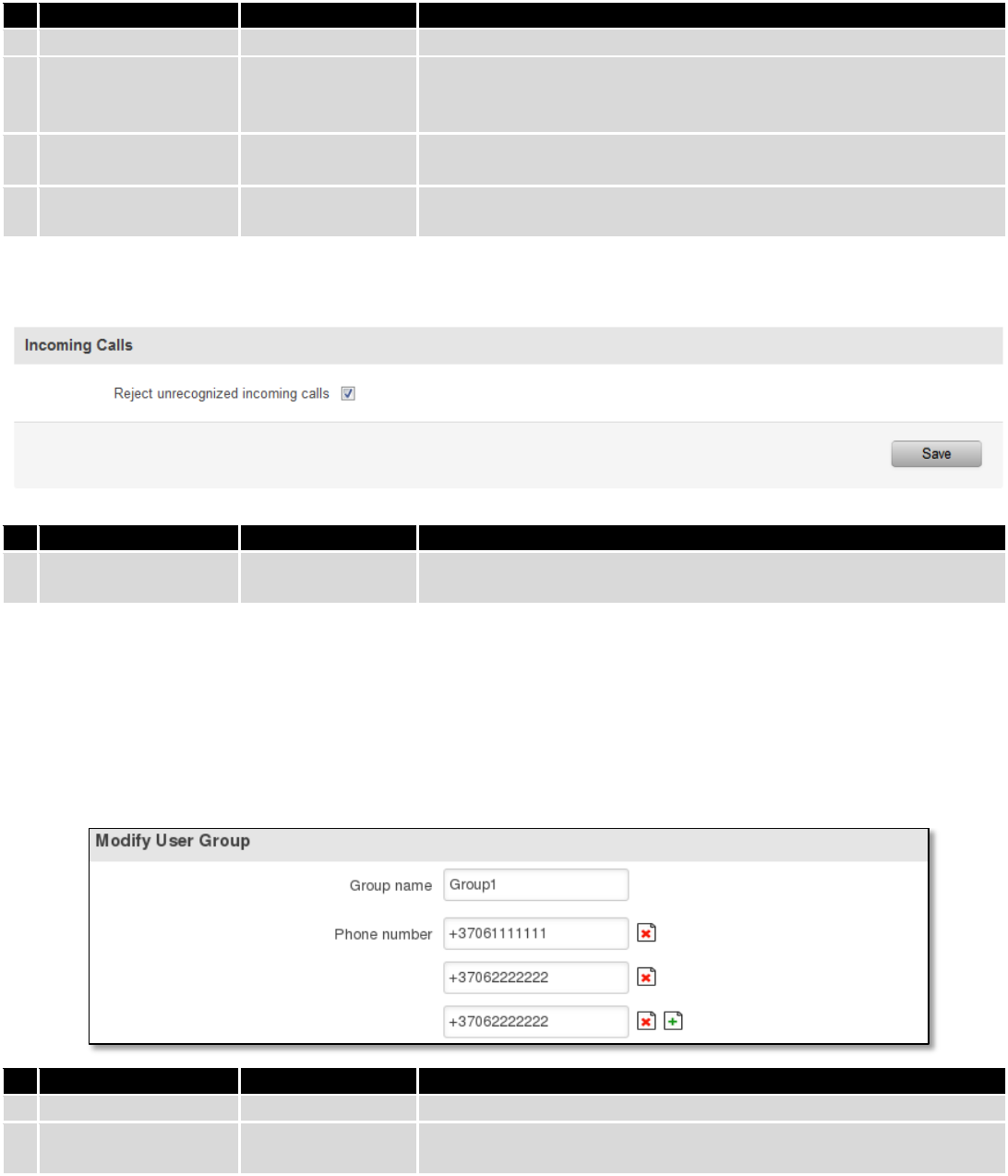
9.7.2.1 Incoming Calls
Field name
Sample
Explanation
1.
Reject unrecognized
incoming calls
Enable/Disable
If a call is made from number that is not in the active rule list, it can
be rejected with this option
9.7.3 User Groups
Give possibility to group phone numbers for SMS management purposes. You can then later use these groups in
all related SMS functionalities. This option helps if there are several Users who should have same roles when managing
router via SMS. You can create new user group by entering group name and clicking on Add button in “Create New User
Group” section. After that you get to “Modify User Group” section.
Field name
Sample
Explanation
1.
Group name
Group1
Name of grouped phone numbers
2.
Phone number
+37061111111
Number to add to users group, must match international format.
You can add phone numbers fields by clicking on the green + symbol
110
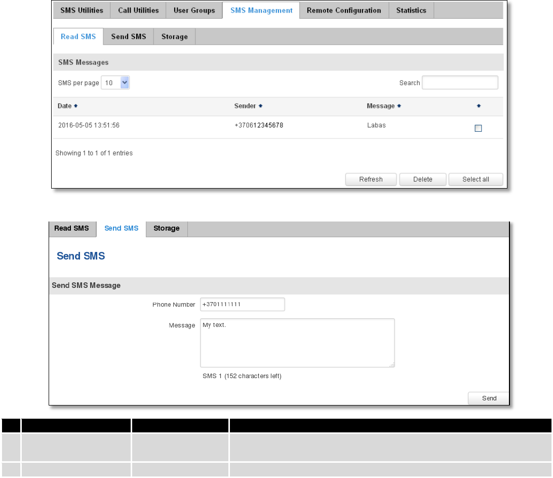
9.7.4 SMS Management
9.7.4.1 Read SMS
In SMS Management page Read SMS you can read and delete received/stored SMS.
9.7.4.2 Send SMS
Field name
Sample
Explanation
1.
Phone number
+3701111111
Recipients phone number. Should be preceded with country code,
i.e. “+370”
2.
Message
My text.
Message text, special characters are allowed.
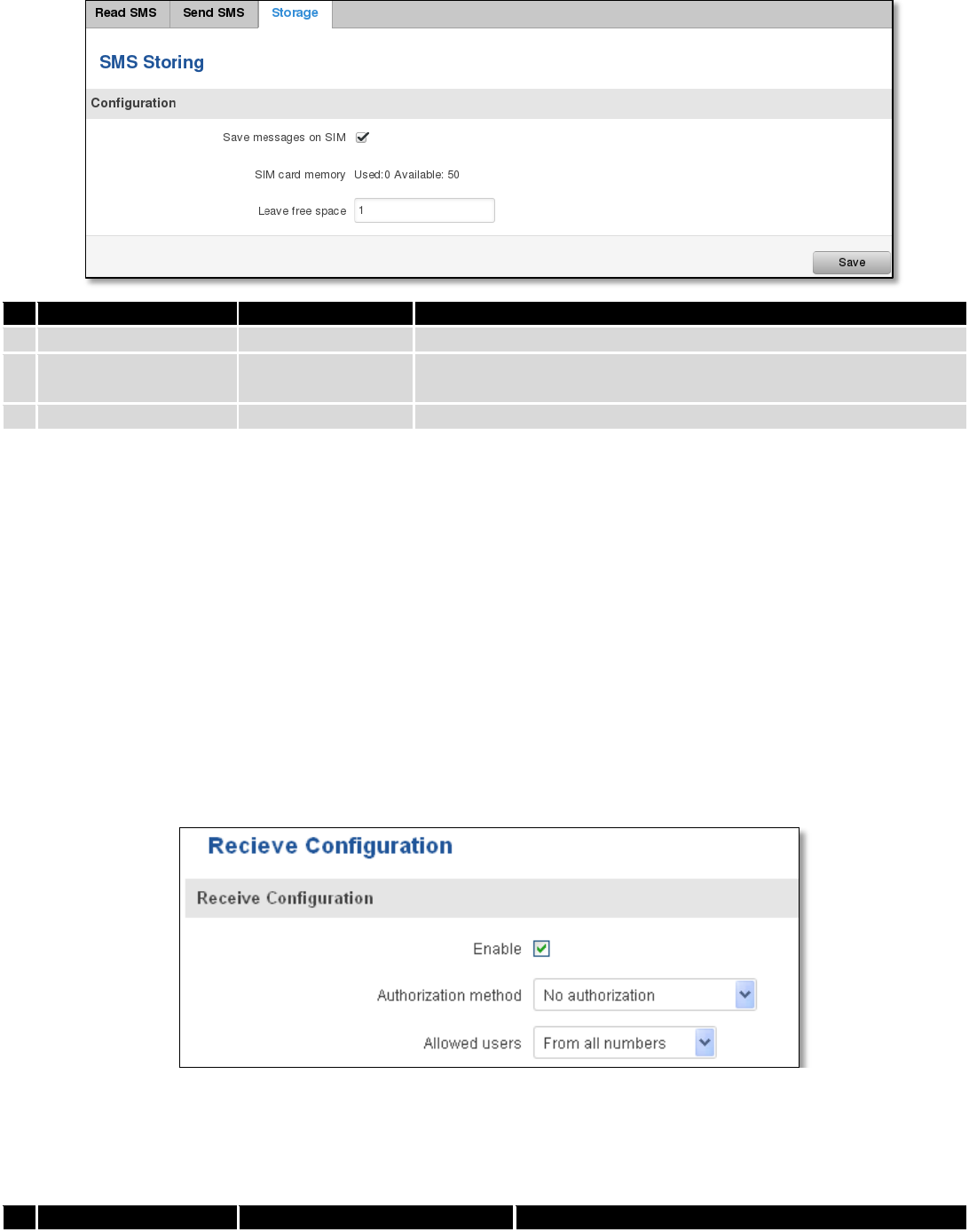
9.7.4.3 Storage
With storage option you can choose for router NOT to delete SMS from SIM card. If this option is not used, router
will automatically delete all incoming messages after they have been read. Message status “read/unread” is examined
every 60 seconds. All “read” messages are deleted.
111
Field name
Sample
Explanation
1.
Save messages on SIM
Enabled / Disabled
Enables received message storing on SIM card
2.
SIM card memory
Used: 0
Available: 50
Information about used/available SIM card memory
3.
Leave free space
1
How much memory (number of message should be left free
9.7.5 Remote Configuration
RUT9xx can be configured via SMS from another RUT9xx. You only have to select which configuration details have
to be sent, generate the SMS Text, type in the phone number and Serial number of the router that you wish to configure
and Send the SMS.
Total count of SMS is managed automatically. You should be aware of possible number of SMS and use this
feature at your own responsibility. It should not, generally, be used if you have high cost per SMS. This is especially
relevant if you will try to send whole OpenVPN configuration, which might acumulate ~40 SMS.
9.7.5.1 Receive configuration
This section controls how configuration initiation party should identify itself. In this scenario RUT950 itself is being
configured.
Field name
Values
Notes
112
1.
Enable
Enabled / Disabled
Enables router to receive configuration
1.
Authorization method
No authorization /
By serial
By administration password
Describes what kind of authorization to use for SMS
management. Method at Receiving and Sending ends
must match
2.
Allowed users
From all numbers
From group
From single number
Gives greater control and security measures
Note, that for safety reasons Authorization method should be configured before deployment of the router.
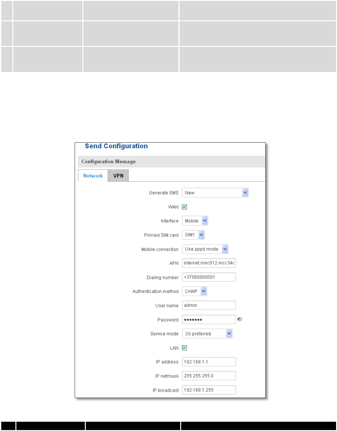
9.7.5.2 Send configuration
This section lets you configure remote RUT950 devices. The authorization settings must confirm to those that are
set on the receiving party.
Field name
Values
Notes

113
1.
Generate SMS
New/From current
configuration
Generate new SMS settings or use current device
configuration
2.
Interface
Mobile/Wired
Interface type used for WAN (Wide Area Network)
connection
3.
WAN
Enable/Disable
Include configuration for WAN (Wide Area Network)
4.
LAN
Enable/Disable
Include configuration for LAN (Local Area Network)
6.
Protocol
Static/DHCP
Network protocol used for network configuration
parameters management
7.
IP address
“217.147.40.44”
IP address that router will use to connect to the
internet
8.
IP netmask
“255.255.255.0”
That will be used to define how large the WAN (Wide
Area Network) network is
11.
IP gateway
“217.147.40.44”
The address where traffic destined for the internet is
routed to
12.
IP broadcast
“217.147.40.255”
A logical address at which all devices connected to a
multiple-access communications network are enabled
to receive datagrams.
13.
Primary SIM card
SIM1/SIM2
A SIM card that will be used as primary
14.
Mobile connection
Use pppd mode
Use ndis mode
An underlying agent that will be used for mobile data
connection creation and management
15.
APN
“internet.mnc012.mcc345.gprs”
(APN) is the name of a gateway between a GPRS or
3G mobile networks and another computer network,
frequently the public Internet.
16.
Dialing number
“+37060000001”
A phone number that will be used to establish a
mobile PPP (Point-to-Point Protocol) connection
17.
Authentication
method
CHAP/PAP/None
Select an authentication method that will be used to
authenticate new connections on your GSM carrier's
network
18.
User name
“admin”
User name used for authentication on your GSM
carrier's network
19.
Password
“password”
Password used for authentication on your GSM
carrier's network
20.
Service mode
Auto
4G (LTE ) preferred
4G (LTE) only
3G preferred
3G only
2G preferred
2G only
You can add as many phone numbers as you need.
Dropdown list with additional rows will show up if
you click on “add” icon at the end of phone number
row.
21.
IP address
“192.168.1.1”
IP address that router will use on LAN (Local Area
Network) network
22.
IP netmask
“255.255.255.0”
A subnet mask that will be used to define how large
the LAN (Local Area Network) network is
23.
IP broadcast
“192.168.1.255”
A logical address at which all devices connected to a
multiple-access communications network are enabled
to receive datagrams
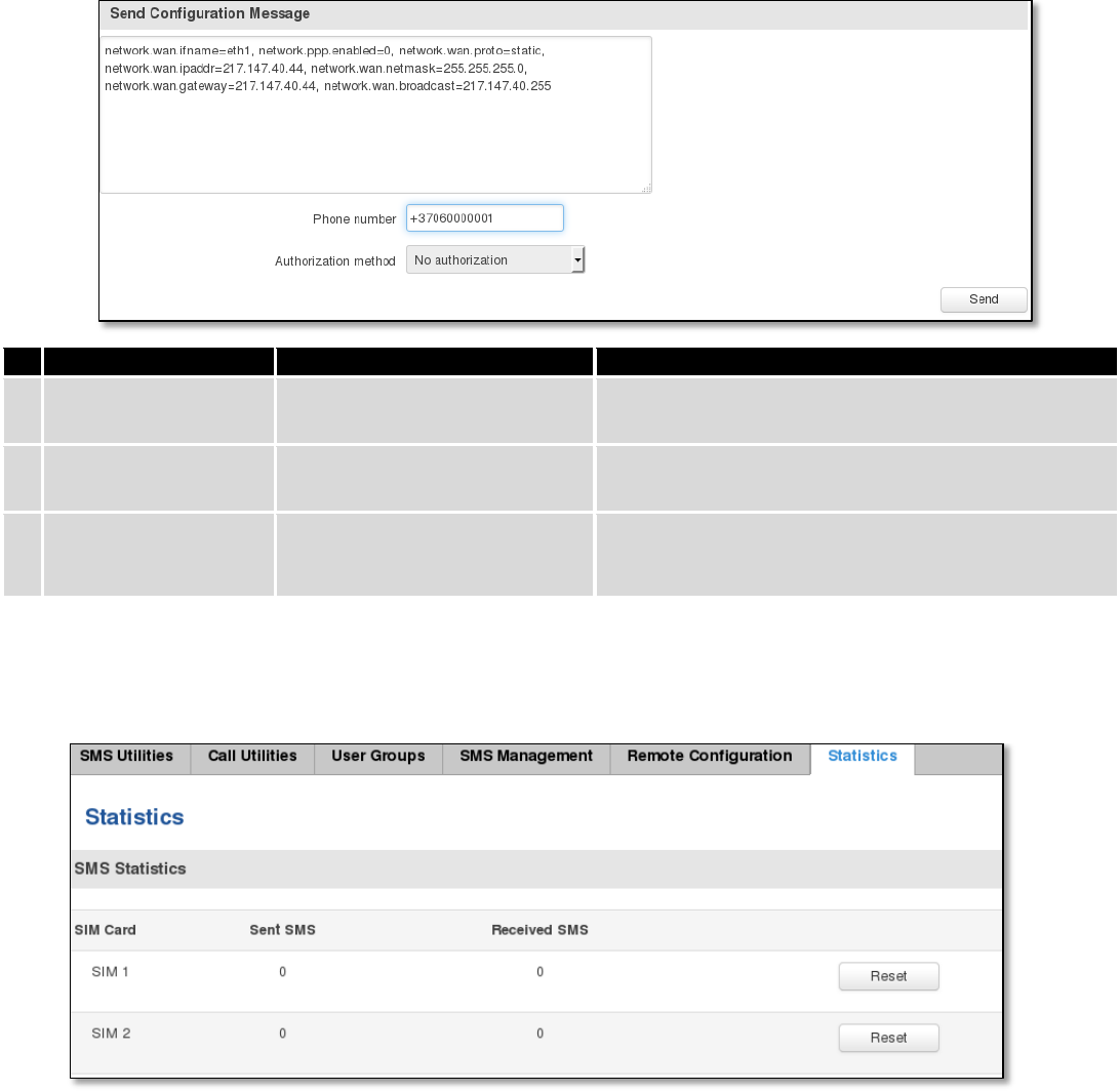
114
Field name
Values
Notes
1.
Message text field
Generated configuration
message
Here you can review and modify configuration
message text to be sent
2.
Phone number
“+37060000001”
A phone number of router which will receive the
configuration
3.
Authorization method
No authorization
By serial
By router admin password
What kind of authorization to use for remote
configuration
9.7.6 Statistics
In statistics page you can review how much SMS was sent and received on both SIM card slots. You can also reset
the counters.
9.8 SNMP
SNMP settings window allows you to remotely monitor and send GSM event information to the server.

115
9.8.1 SNMP Settings
Field name
Sample
Explanation
1.
Enable SNMP service
Enable/Disable
Run SNMP (Simple Network Management Protocol) service on
system's start up
2.
Enable remote access
Enable/Disable
Open port in firewall so that SNMP (Simple Network
Management Protocol) service may be reached from WAN
3.
Port
161
SNMP (Simple Network Management Protocol) service's port
4.
Community
Public/Private/Custom
The SNMP (Simple Network Management Protocol) Community
is an ID that allows access to a router's SNMP data
5.
Community name
custom
Set custom name to access SNMP
6.
Location
Location
Trap named sysLocation
7.
Contact
email@example.com
Trap named sysContact
8.
Name
Name
Trap named sysName
Variables/OID
OID
Description
1.
1.3.6.1.4.1.99999.1.1.1
Modem IMEI
2.
1.3.6.1.4.1.99999.1.1.2
Modem model
3.
1.3.6.1.4.1.99999.1.1.3
Modem manufacturer
4.
1.3.6.1.4.1.99999.1.1.4
Modem revision
5.
1.3.6.1.4.1.99999.1.1.5
Modem serial number
6.
1.3.6.1.4.1.99999.1.1.6
SIM status
7.
1.3.6.1.4.1.99999.1.1.7
Pin status
8.
1.3.6.1.4.1.99999.1.1.8
IMSI
9.
1.3.6.1.4.1.99999.1.1.9
Mobile network registration status
10.
1.3.6.1.4.1.99999.1.1.10
Signal level
11.
1.3.6.1.4.1.99999.1.1.11
Operator currently in use
12.
1.3.6.1.4.1.99999.1.1.12
Operator number (MCC+MNC)
13.
1.3.6.1.4.1.99999.1.1.13
Data session connection state
14.
1.3.6.1.4.1.99999.1.1.14
Data session connection type
15.
1.3.6.1.4.1.99999.1.1.15
Signal strength trap
16.
1.3.6.1.4.1.99999.1.1.16
Connection type trap
116
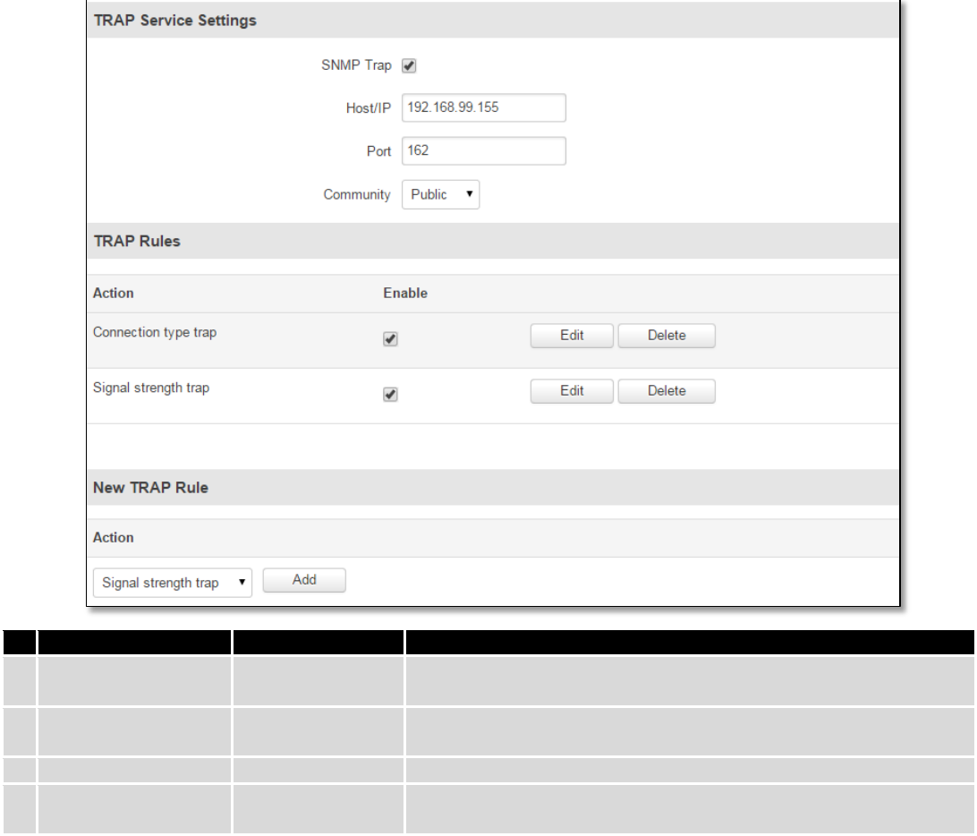
9.8.2 TRAP Settings
Field name
Sample
Explanation
1.
SNMP Trap
Enable/Disable
Enable SNMP (Simple Network Management Protocol) trap
functionality
2.
Host/IP
192.168.99.155
Host to transfer SNMP (Simple Network Management Protocol)
traffic to
3.
Port
162
Port for trap's host
4.
Community
Public/Private
The SNMP (Simple Network Management Protocol) Community is an
ID that allows access to a router's SNMP data
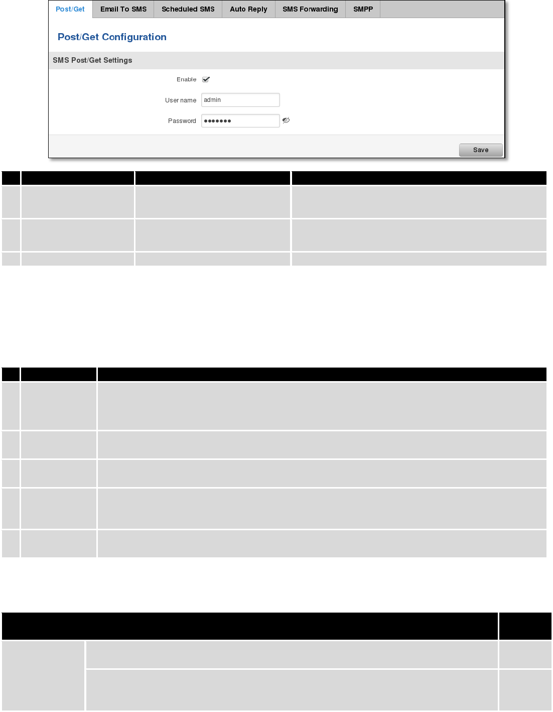
9.9 SMS Gateway
9.9.1 Post/Get Configuration
Post/Get Configuration allows you to perform actions by writing these requests URI after your device IP address.
117
Field name
Values
Notes
1.
Enable
Enabled / Disabled
Enable SMS management functionality through
POST/GET
2.
User name
admin
User name used for authorization
3.
Password
*******
Password used for authorization (default- admin01)
Do not forget to change parameters in the url according to your POST/GET Configuration!
9.9.1.1 SMS by HTTP POST/GET
It is possible to read and send SMS by using valid HTTP POST/GET syntax. Use web browser or any other
compatible software to submit HTTP POST/GET string to router. Router must be connected to GSM network when using
“SMS send” feature.
Action
POST/GET url e.g.
1.
View mobile
messages list
/cgi-bin/sms_list?username=admin&password=admin01
2.
Read mobile
message
/cgi-bin/sms_read?username=admin&password=admin01&number=1
3.
Send mobile
messages
/cgi-bin/sms_send?username=admin&password=admin01&number=0037060000001&text=testmessage
4.
View mobile
messages
total
/cgi-bin/sms_total?username=admin&password=admin01
5.
Delete mobile
message
/cgi-bin/sms_delete?username=admin&password=admin01&number=1
9.9.1.2 Syntax of HTTP POST/GET string
HTTP POST/GET string
Explanati
on
http://{IP_ADD
RESS}
/cgi-bin/sms_read?
username={your_user_name}&password={your_password}&number={MESSAGE_INDEX}
Read
message
/cgi-bin/sms_send?
username={your_user_name}&password={your_password}&number={PHONE_NUMBER}
&text={MESSAGE_TEXT}
Send
message

118
/cgi-bin/sms_delete?
username={your_user_name}&password={your_password}&number={MESSAGE_INDEX}
Delete
message
/cgi-bin/ sms_list? username={your_user_name}&password={your_password}
List all
message
s
/cgi-bin/sms_ total? username={your_user_name}&password={your_password}
Number
of
message
s in
memory
Note: parameters of HTTP POST/GET string are in capital letters inside curly brackets. Curly brackets (“{ }”) are not
needed when submitting HTTP POST/GET string.
9.9.1.3 Parameters of HTTP POST/GET string
Parameter
Explanation
1.
IP_ADDRESS
IP address of your router
2.
MESSAGE_INDEX
SMS index in memory
3.
PHONE_NUMBER
Phone number of the message receiver.
Note: Phone number must contain country code. Phone number format is:
00{COUNTRY_CODE} {RECEIVER_NUMBER}.
E.g.: 0037062312345 (370 is country code and 62312345 is receiver phone number)
4.
MESSAGE_TEXT
Text of SMS. Note: Maximum number of characters per SMS is 160. You cannot send
longer messages. It is suggested to use alphanumeric characters only.
After every executed command router will respond with return status.
9.9.1.4 Possible responses after command execution
Response
Explanation
1.
OK
Command executed successfully
2.
ERROR
An error occurred while executing command
3.
TIMEOUT
No response from the module received
4.
WRONG_NUMBER
SMS receiver number format is incorrect or SMS index number is incorrect
5.
NO MESSAGE
There is no message in memory by given index
6.
NO MESSAGES
There are no stored messages in memory
9.9.1.5 HTTP POST/GET string examples
http://192.168.1.1/cgi-bin/sms_read?username=admin&password=admin01&number=2
http://192.168.1.1/cgi-bin/sms_send?username=admin&password=admin01&number=0037060000001&text=message
http://192.168.1.1/cgi-bin/sms_delete?username=admin&password=admin01&number=4
http://192.168.1.1 /cgi-bin/sms_list?username=admin&password=admin01
http://192.168.1.1/cgi-bin/sms_total?username=admin&password=admin01
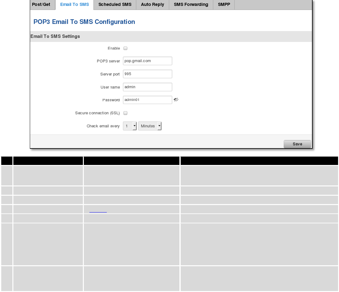
119
9.9.2 Email to SMS
Field name
Values
Notes
1.
Enable
Enable/Disable
Allows to convert received Email to SMS
2.
POP3 server
“pop.gmail.com”
POP3 server address
3.
Server port
“995”
Server authentication port
4.
User name
“admin”
User name using for server authentication
5.
Password
“admin01”
Password using for server authentication
6.
Secure connection
(SLL)
Enable/Disable
(SSL) is a protocol for transmitting private documents
via the Internet. SSL uses a cryptographic system that
uses two keys to encrypt data − a public key known to
everyone and a private or secret key known only to
the recipient of the message.
7.
Check mail every
Minutes
Hours
Days
Mail checking period
9.9.3 Scheduled Messages
Scheduled messages allow to periodically sending mobile messages to specified number.
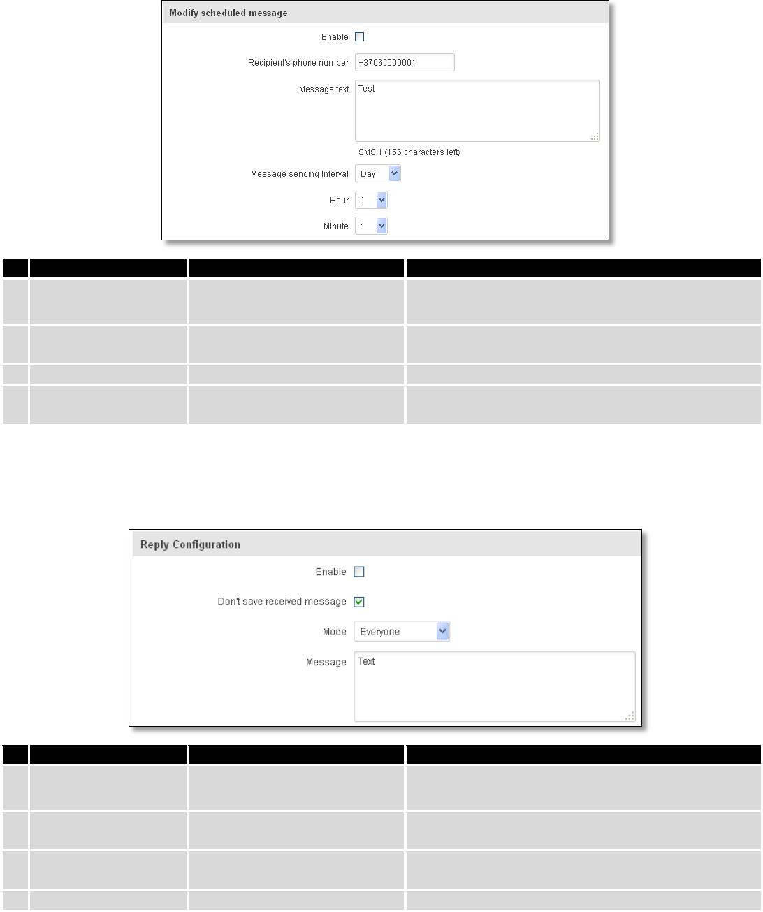
120
9.9.3.1 Scheduled Messages Configuration
Field name
Values
Notes
1.
Enable
Enable/Disable
Activates periodical messages sending.
2.
Recipient’s phone
number
“+37060000001”
Phone number that will receive messages.
3.
Message text
“Test”
Message that will be send.
4.
Message sending
interval
Day/Week/Month/Year
Message sending period.
9.9.4 Auto Reply Configuration
Auto reply allows replying to every message that router receives to everyone or to listed numbers only.
Field name
Values
Notes
1.
Enable
Enable/Disable
Enable auto reply to every received mobile message.
2.
Don’t save received
message
Enable/Disable
If enabled, received messages are not going to be
saved
3.
Mode
Everyone /
Listed numbers
Specifies from which senders received messages are
going to be replied.
4.
Message
“Text”
Message text that will be sent in reply.
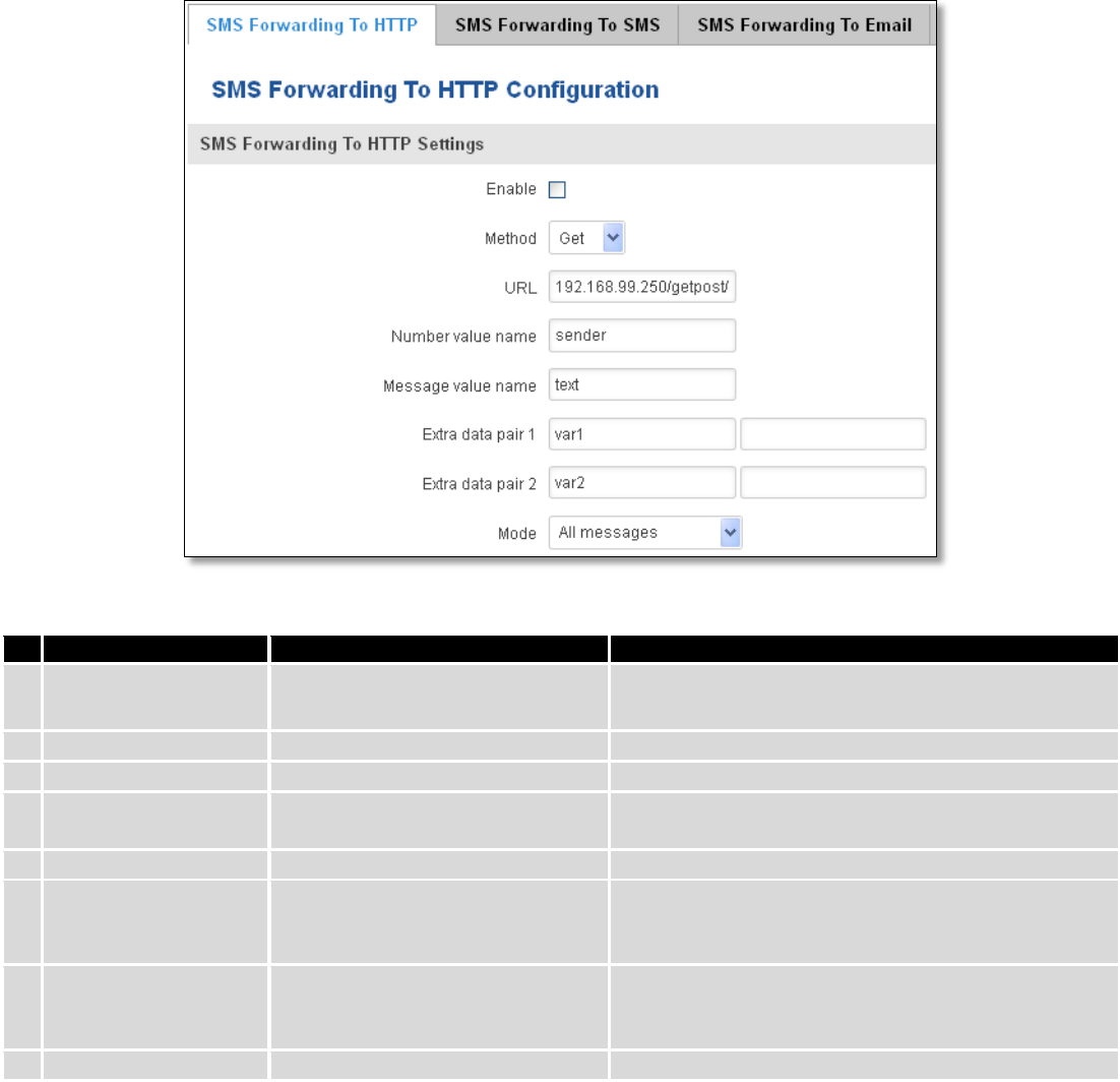
121
9.9.5 SMS Forwarding
9.9.5.1 SMS Forwarding To HTTP
This functionality forwards mobile messages from all or only specified senders to HTTP, using either POST or GET
methods.
Field name
Values
Notes
1.
Enable
Enable / Disable
Enable mobile message forwarding to HTTP
2.
Method
POST / GET
Defines the HTTP transfer method
3.
URL
192.168.99.250/getpost/index.php
URL address to forward messages to
4.
Number value name
“sender”
Name to assign for sender’s phone number value in
query string
5.
Message value name
“text”
Name to assign for message text value in query string
6.
Extra data pair 1
Var1 - 17
If you want to transfer some extra information
through HTTP query, enter variable name on the left
field and its value on the right
7.
Extra data pair 2
Var2 – “go”
If you want to transfer some extra information
through HTTP query, enter variable name on the left
field and its value on the right
8.
Mode
All messages/From listed numbers
Specifies which senders messages to forward
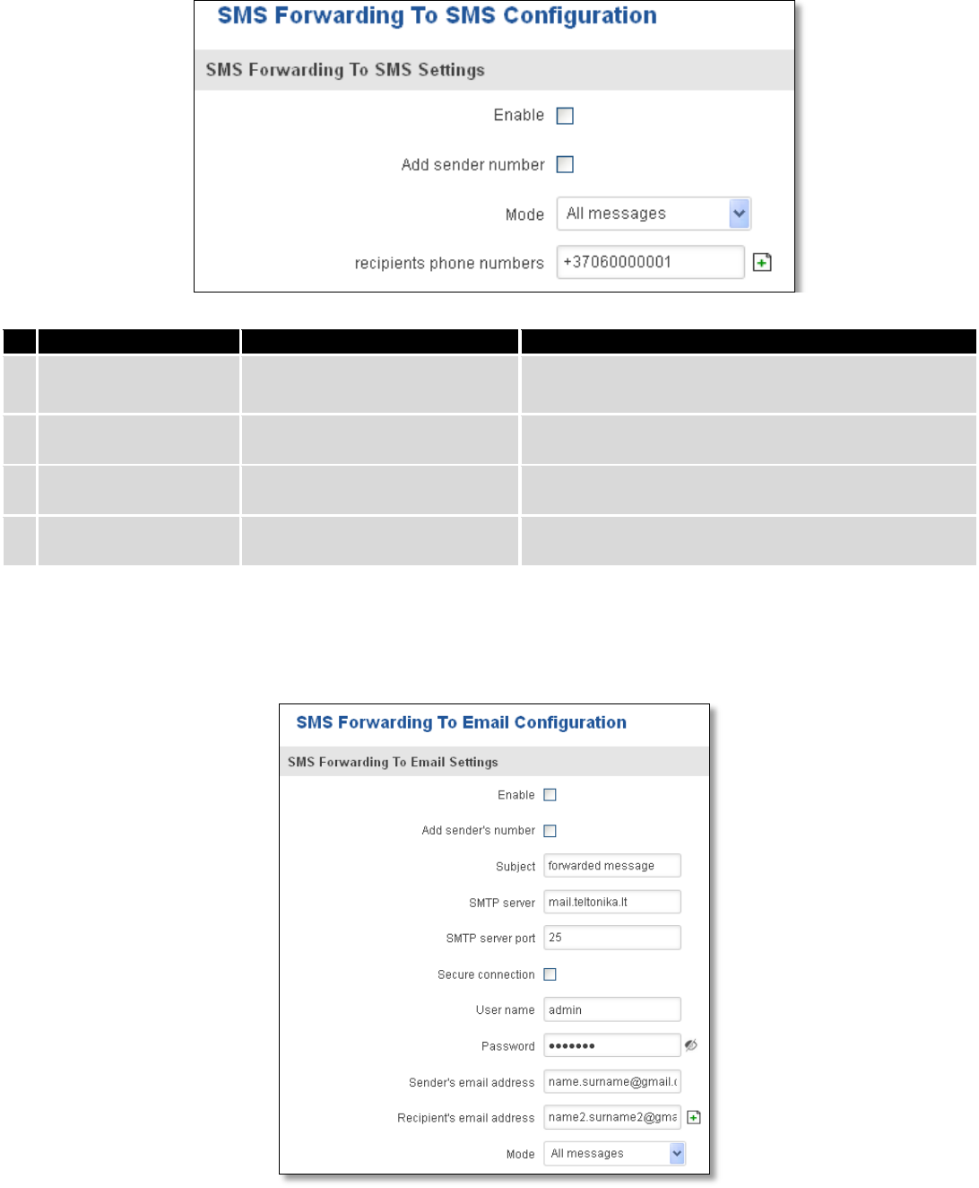
122
9.9.5.2 SMS Forwarding to SMS
This functionality allows forwarding mobile messages from specified senders to one or several recipients.
Field name
Values
Notes
1.
Enable
Enable / Disable
Enable mobile message forwarding
2.
Add sender number
Enable / Disable
If enabled, original senders number will be added at
the end of the forwarded message
3.
Mode
All message /
From listed numbers
Specifies from which senders received messages are
going to be forwarded.
4.
Recipients phone
numbers
+37060000001
Phone numbers to which message is going to be
forwarded to
9.9.5.3 SMS Forwarding to Email
This functionality forwards mobile messages from one or several specified senders to email address.
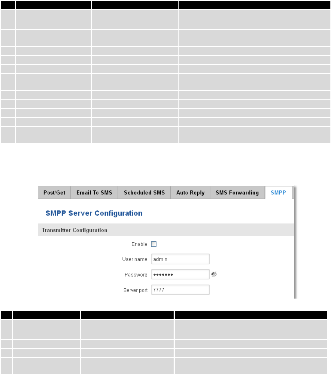
123
Field name
Values
Notes
1.
Enable
Enable / Disable
Enable mobile message forwarding to email
2.
Add sender number
Enable / Disable
If enabled, original senders number will be added at
the end of the forwarded message
3.
Subject
“forwarded message”
Text that will be inserted in email Subject field
4.
SMTP server
mail.teltonika.lt
Your SMTP server’s address
5.
SMTP server port
25
Your SMTP server’s port number
6.
Secure connection
Enable / Disable
Enables the use of cryptographic protocols, enable
only if your SMTP server supports SSL or TLS
7.
User name
“admin”
Your full email account user name
8.
Password
*******
Your email account password
9.
Sender’s email address
name.surname@gmail.com
Your address that will be used to send emails from
10.
Recipient’s email address
name2.surname2@gmail.com
Address that you want to forward your messages to
11.
Mode
All messages / from listed
numbers
Choose which senders messages to forward to email
9.9.6 SMPP
Field name
Values
Explanation
1.
Enable
Enable/Disable
Enables SMPP server
2.
User name
admin
User name for authentication on SMPP server
3.
Password
●●●●●●●
Password for authentication on SMPP server
4.
Server port
7777
A port will be used for SMPP server communications.
Allowed all not used ports [0-65535]
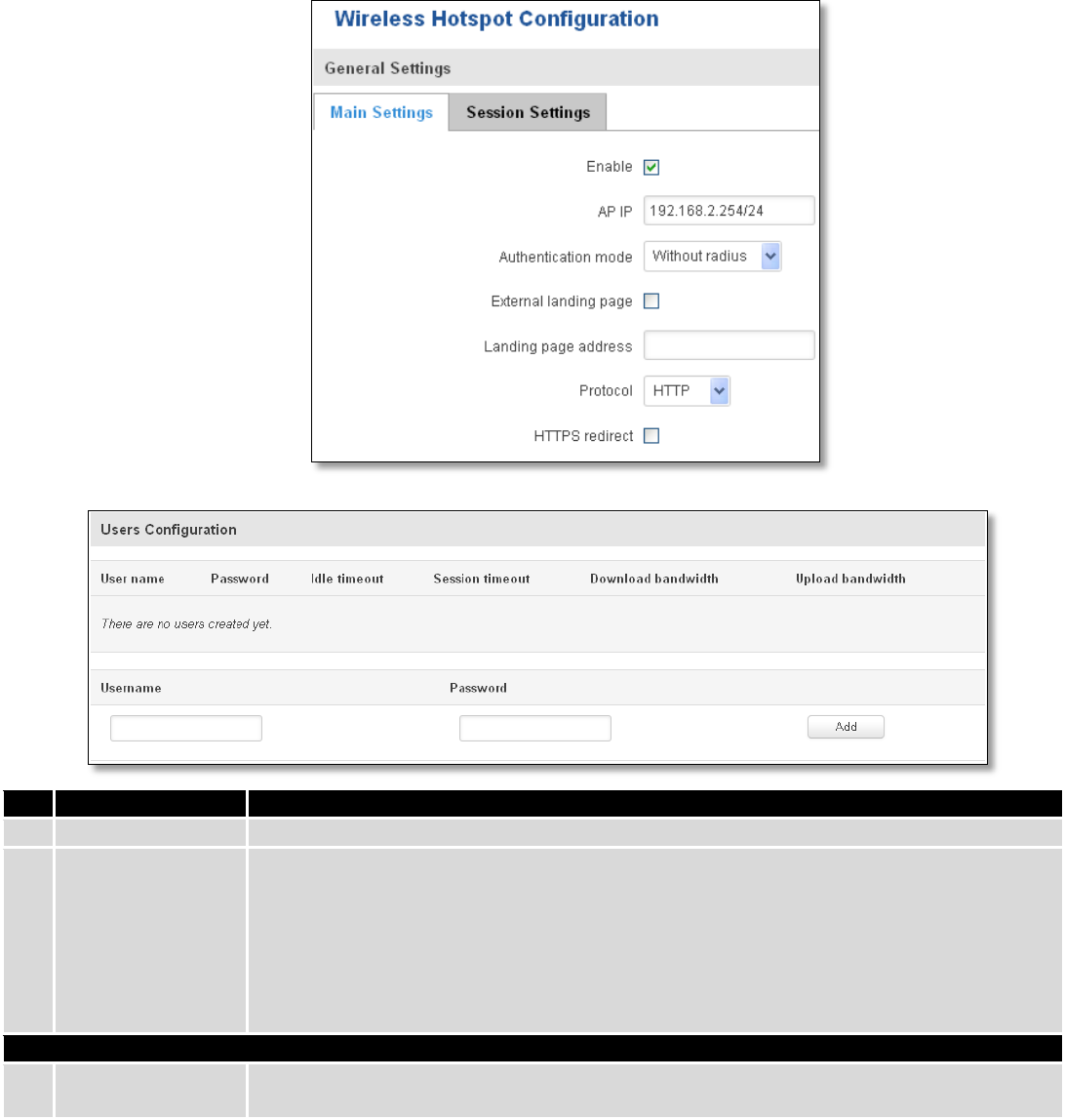
124
9.10 Hotspot
Wireless hotspot provides essential functionality for managing an open access wireless network. In
addition to standard RADIUS server authentication there is also the ability to gather and upload detailed logs on
what each device (denoted as a MAC address) was doing on the network (what sites were traversed, etc.).
9.10.1 General settings
9.10.1.1 Main settings
Field name
Explanation
1.
Enabled
Check this flag to enable hotspot functionality on the router.
2.
AP IP
Access Point IP address. This will be the address of the router on the hotspot network. The
router will automatically create a network according to its own IP and the CIDR number
that you specify after the slash. E.g. “192.168.2.254/24” means that the router will create
a network with the IP address 192.168.182.0, netmask 255.255.255.0 for the express
purpose of containing all the wireless clients. Such a network will be able to have 253
clients (their IP addresses will be automatically granted to them and will range from
192.168.2.1 to 192.168.2.253).
Authentication mode: External radius
1.
Radius server #1
The IP address of the RADIUS server that is to be used for Authenticating your wireless
clients.
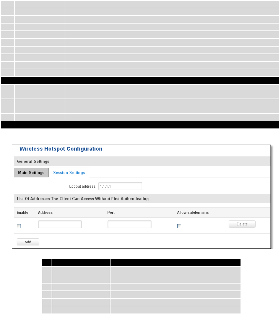
125
2.
Radius server #2
The IP address of the second RADIUS server.
3.
Authentication port
RADIUS server authentication port.
4.
Accounting port
RADIUS server accounting port.
5.
Radius secret key
The secret key is used for authentication with the RADIUS server
6.
UAM port
Port to bind for authenticating clients
7.
UAM UI port
UAM UI port
8.
UAM secret
Shared secret between UAM server an hotspot
9.
NAS Identifier
NAS Identifier
10.
Swap octets
Swap the meaning of input octets and output as it related to RADIUS attributes
11.
Location name
The name of location
Authentication mode: Internal radius/Without radius
1.
External landing
page
Enables the use of external landing page.
2.
Landing page
address
The address of external landing page
3.
HTTPS redirect
Redirects HTTP pages to landing page.
Authentication mode: SMS OTP
9.10.1.2 Session settings
Field name
Explanation
1.
Logout address
IP address to instantly logout a client addressing it
2.
Enable
Enable address accessing without first authenticating
3.
Address
Domain name, IP address or network segment
4.
Port
Port number
5.
Allow subdomains
Enable/Disable subdomains
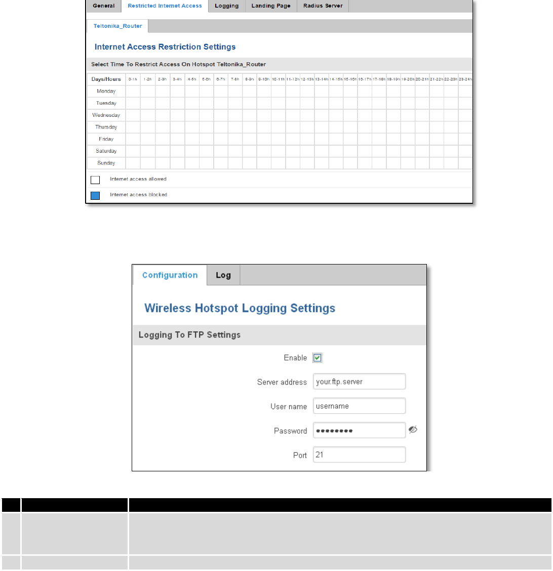
126
9.10.2 Internet Access Restriction Settings
Allows disable internet access on specified day and hour of every week.
9.10.3 Logging
9.10.3.1 Configuration
Field name
Explanation
1.
Enable
Check this box if you want to enable wireless traffic logging. This feature will produce logs
which contain data on what websites each client was visiting during the time he was
connected to your hotspot.
2.
Server address
The IP address of the FTP server to which you want the logs uploaded.
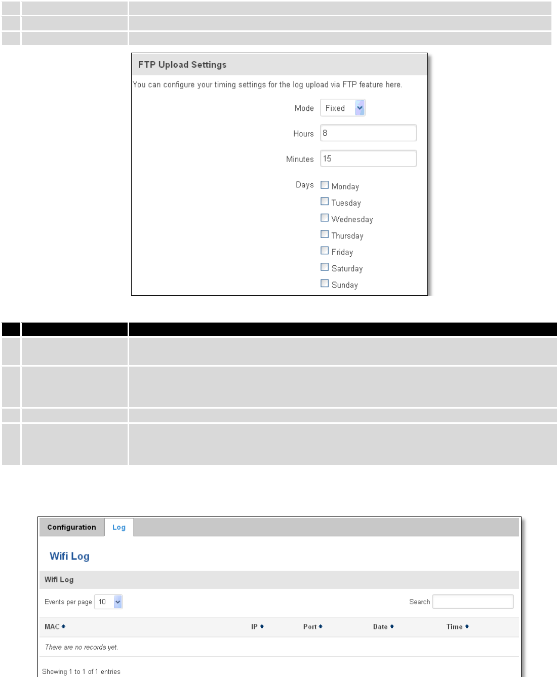
127
3.
Username
The username of the user on the aforementioned FTP server.
4.
Password
The password of the user.
5.
Port
The TCP/IP Port of the FTP server.
Field name
Explanation
1.
Mode
The mode of the schedule. Use “Fixed” if you want the uploading to be done on a specific
time of the day. Use “Interval” if you want the uploading to be done at fixed interval.
2.
Interval
Shows up only when “Mode” is set to Interval. Specifies the interval of regular uploads on
one specific day. E.g. If you choose 4 hours, the uploading will be done on midnight, 4:00,
8:00, 12:00, 16:00 and 20:00.
3.
Days
Uploading will be performed on these days only
4.
Hours, Minutes
Shows up only when “Mode” is set to Fixed. Uploading will be done on that specific time of
the day. E.g. If you want to upload your logs on 6:48 you will have to simply enter hours: 6
and minutes: 48.
9.10.3.2 Log
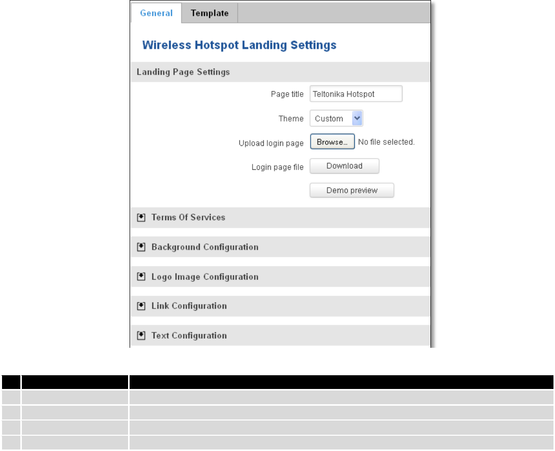
128
9.10.4 Landing Page
9.10.4.1 General Landing Page Settings
With this functionality you can customize your Hotspot Landing page.
Field name
Explanation
1.
Page title
Will be seen as landing page title
2.
Theme
Landing page theme selection
3.
Upload login page
Allows to upload custom landing page theme
4.
Login page file
Allows to download and save your landing page file
In the sections – “Terms Of Services”, “Background Configuration”, “Logo Image Configuration”, “Link
Configuration”, “Text Configuration” you can customize various parameters of landing page components.
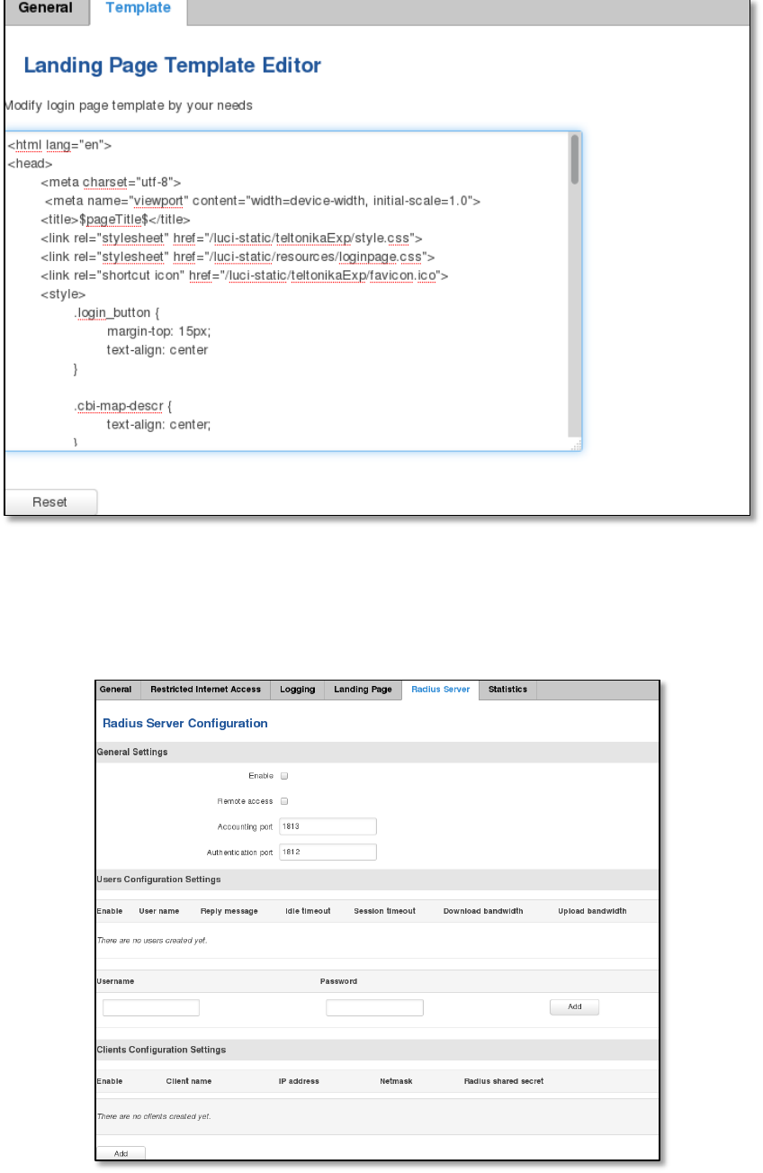
129
9.10.4.2 Template
In this page you can review landing page template HTML code and modify it.
9.10.5 Radius server configuration
An authentication and accounting system used by many Internet Service Providers (ISPs). When you dial in to the
ISP you must enter your username and password. This information is passed to a RADIUS server, which checks that the
information is correct, and then authorizes access to the ISP system.
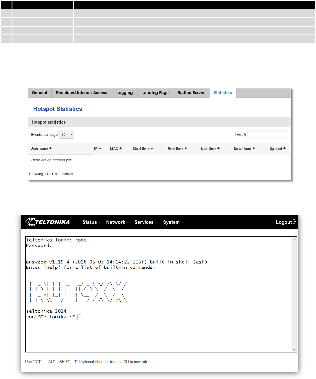
130
Field name
Explanation
1.
Enable
Activates an authentication and accounting system
2.
Remote access
Activates remote access to radius server
3.
Accounting port
Port on which to listen for accounting
4.
Authentication port
Port on which to listen for authentication
9.10.6 Statistics
On hotspot statistics page you can review statistical information about hotspot instances.
9.11 CLI
CLI or Comand Line Interface functionality allows you to enter and execute comands into routers terminal.
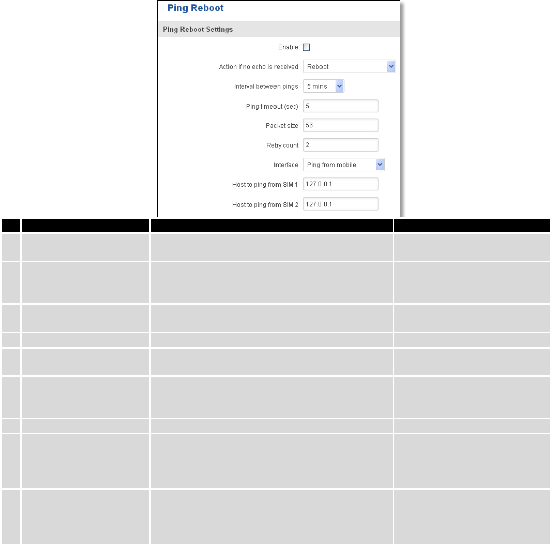
131
9.12 Auto Reboot
9.12.1 Ping Reboot
Ping Reboot function will periodically send Ping command to server and waits for echo receive. If no echo is
received router will try again sending Ping command defined number times, after defined time interval. If no echo is
received after the defined number of unsuccessful retries, router will reboot. It is possible to turn of the router
rebooting after defined unsuccessful retries. Therefore this feature can be used as “Keep Alive” function, when router
Pings the host unlimited number of times. Possible actions if no echo is received: Reboot, Modem restart, Restart
mobile connection, (Re) register, None.
Field name
Explanation
Notes
1.
Enable
This check box will enable or disable Ping reboot
feature.
Ping Reboot is disabled by
default.
2.
Action if no echo is
received
Action after the defined number of unsuccessful
retries
No echo reply for sent ICMP
(Internet Control Message
Protocol) packet received
3.
Interval between pings
Time interval in minutes between two Pings.
Minimum time interval is 5
minutes.
4.
Ping timeout (sec)
Time after which consider that Ping has failed.
Range(1-9999)
5.
Packet size
This box allows to modify sent packet size
Should be left default, unless
necessary otherwise
6.
Retry count
Number of times to try sending Ping to server after
time interval if echo receive was unsuccessful.
Minimum retry number is 1.
Second retry will be done after
defined time interval.
8.
Interface
Interface used for connection
7.
Host to ping from SIM 1
IP address or domain name which will be used to
send ping packets to. E.g. 127.0.0.1 (or
www.host.com if DNS server is configured
correctly)
Ping packets will be sending
from SIM1.
8.
Host to ping from SIM 2
IP address or domain name which will be used to
send ping packets to. E.g. 127.0.0.1 (or
www.host.com if DNS server is configured
correctly)
Ping packets will be sending
from SIM2.
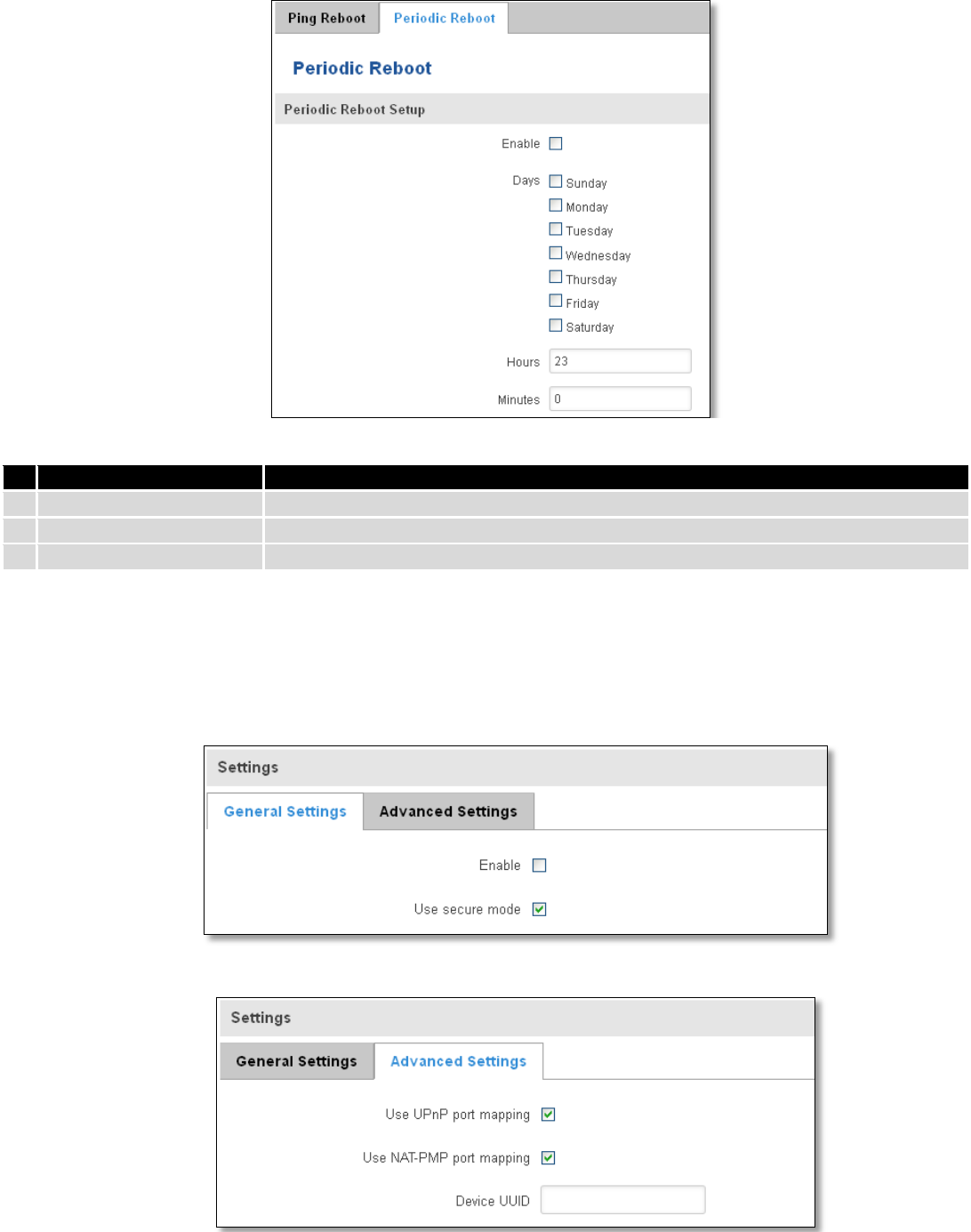
132
9.12.2 Periodic Reboot
Field name
Explanation
1.
Enable
This check box will enable or disable Periodic reboot feature.
2.
Days
This check box will enable router rebooting at the defined days.
3.
Hours, Minutes
Uploading will be done on that specific time of the day
9.13 UPNP
9.13.1 General Settings
UPnP allows clients in the local network to automatically configure the router.
9.13.2 Advanced Settings
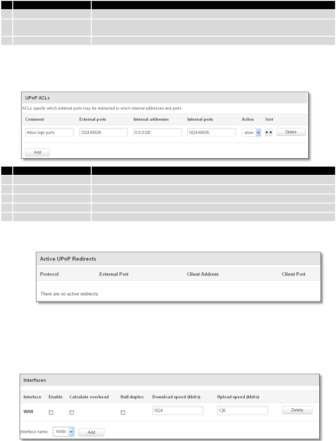
133
Field name
Explanation
1.
Use UPnP port mapping
Enable UPnP port mapping functionality
2.
Use NAT-PMP port
mapping
Enable NAT-PMP mapping functionality
3.
Device UUID
Specify Universal unique ID of the device
9.13.3 UPnP ACLs
ACLs specify which external ports may be redirected to which internal addresses and ports.
Field name
Explanation
1.
Comment
Add comment to this rule
2.
External ports
External ports which may be redirected
3.
Internal addresses
Internal address to be redirect to
4.
Internal ports
Internal ports to be redirect to
5.
Action
Allow or forbid UPNP service to open the specified port
9.13.4 Active UPnP Redirects
9.14 QoS
QoS (Quality of Service) is the idea that transmission rates, error rates, and other characteristics can be measured,
improved, and, to some extent, guaranteed in advance. QoS is of particular concern for the continuous transmission of
high-bandwidth video and multimedia information.
QoS can be improved with traffic shaping techniques such as packet, network traffic, and port prioritization.
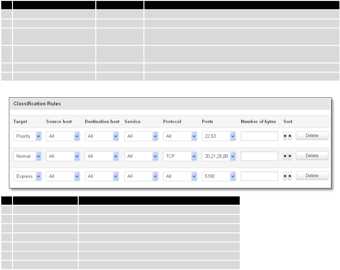
134
Field name
Value
Explanation
1.
Interface
WAN/LAN/PPP
2.
Enable
Enable/Disable
Enable/disable settings
3.
Calculate overhead
Enable/Disable
Check to decrease upload and download ratio to prevent link
saturation
4.
Half-duplex
Enable/Disable
Check to enable data transmission in both direction on a single
carrier
5.
Download speed (kbit/s)
1024
Specify maximal download speed
6.
Upload speed (kbit/s)
128
Specify maximal upload speed
Field name
Explanation
1.
Target
Select target for which rule will be applied
2.
Source host
Select host from which data will be transmitted
3.
Destination host
Select host to which data will be transmitted
4.
Service
Select service for which rule will be applied
5.
Protocol
Select data transmission protocol
6.
Ports
Select which port will be used for transmission
7.
Number of bytes
Specify the maximal number of bytes for connection
9.15 MQTT
MQTT also known as MQ Telemetry Transport is an publish-subscribe based messaging protocol for use on top of
the TCP/IP protocol. It is designed to send short messages from one client (publisher) to another (subscriber) through
the brokers, which are responsible for message delivery to the end point. RUT 9XX routers do support this functionality
via open source Mosquitto broker. The messages are sent in this way: some client (subscriber) subscribes to specific
topic or many of them, and then publisher posts some message to specific topic. The broker then checks who is
subscribed to particular topic and transmits data from publisher to subscriber.
RUT9XX supports some functionality of the MQTT broker and MQTT publisher. The main window of parameters is
presented below. The broker can be enabled by checking Enable and entering the port number on which MQTT broker
should run to. In order to accept connections from WAN interface, Enable Remote Access should be checked also.
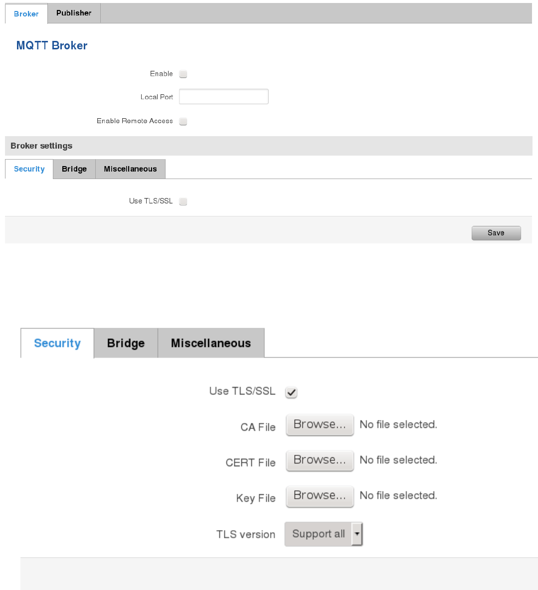
135
In order to use TLS/SSL for connecting clients (subscribers and publishers) to the broker, the one should check
Use TLS/SSL. After that, additional settings will be displayed to the user as shown below. Here the user can upload
certificates, key files and choose TLS version, which will be used for data encryption between broker and clients
(subscribers and publishers)
The MQTT broker also supports option called Bridge. It means, that two brokers can be connected to each other
and share messages. The window of bridge parameters are presented below. There are some mandatory parameters,
like Connection Name, Remote Address and Remote Port. Although connection name is mandatory, it should be set to
value what you like and according to mosquitto’s user manual this option denotes the client ID which will be used when
connecting to remote broker. There are some other parameters. If you would like to known that they mean and how to
use them you should check for mosquito.conf manual page.
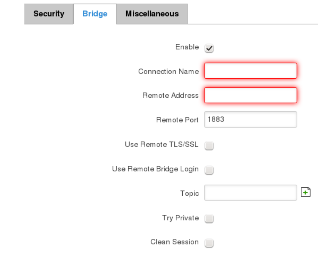
136
,
The last section of parameters is called Miscellaneous. It contains parameters, which does not depend on neither
Security, nor Bridge categories. ACL File denotes access control list file name. The contents of this file are used to control
client access to topics of the broker. The Password File denotes the file, there users and corresponding passwords are
stored. This file is used for user authentication. This option is related to another option called Allow Anonymous. If
Allow Anonymous is unchecked, only users, which exist in password file will be able to connect to the broker. More
about password file can be read on mosquitto configuration manual. The last option is called Persistence, it allows to
save connection, subscription and message data to the disk, otherwise, the data is stored in memory only.

137
It is possible to configure some sort of MQTT publisher. It is not simple publisher, but publisher, which publishes
some system parameters to the broker. The publisher configuration window has few fields, like hostname and port of
the broker to connect. Username and password fields are used for authentication. If these fields are left empty, no
authentication is performed.
The full list of system parameters, which can be published, are described below.
Parameter name
Parameter description
temperature
Get temperature of the module in 0.1 degrees Celcium
operator
Get current operator’s name
signal
Get signal strength in dBm
network
Get current network type (2G, 3G, 4G, etc’)
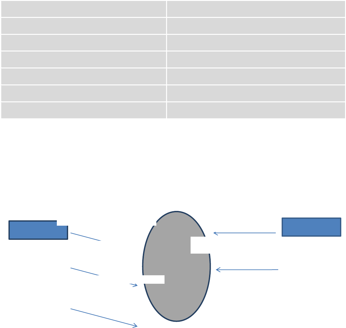
138
connection
Check if data connection is available
wan
Get WAN’s IP address
uptime
Get system uptime in seconds
name
Get router’s name
digital1
Get value of digital input no. 1
digital2
Get value of digital input no. 2
analog
Get value of analog input
In order system to work, MQTT broker should be configured in advance. You can use the broker, which is installed inside
the router, or the broker in the other location. The publisher operates according to the scheme presented below. In the
scheme the client tries to subscribe information about router’s uptime. To achieve this multiple commands between
client and publisher are being sent.
In general publisher works in such a way: connects to the broker and subscribes to the topics router/get and
get/<SERIAL>/command, there <SERIAL> denotes serial number of the router which is currently run publisher. The client
then sends message id to the topic router/get. The following message is received by the publisher, since it is subscribed
to that topic. Then the publisher sends response with its serial number to the topic router/id. Now the client knows that
publisher with some serial number exist. It means, that client can send message with parameter name from the list as a
message to the topic get/<SERIAL>/command to the broker. The message will be received only by the subscriber, which
has the same SERIAL number mentioned in the topic. Now the publisher can send back a response with
router/<SERIAL>/parameter_name topic and message with a value of requested parameter. It should be noted, that
according to MQTT protocol, the topic names are case-sensitive, for example topic router is not the same as topic
RoUtEr.
Publisher
Subscribe router/get
Subscribe
get/01234567/command
Publish router/get
id
Publish router/id
01234567
Publish get/01234567/command
uptime
Broke
r
Client
Publish router/01234567/uptime 15248
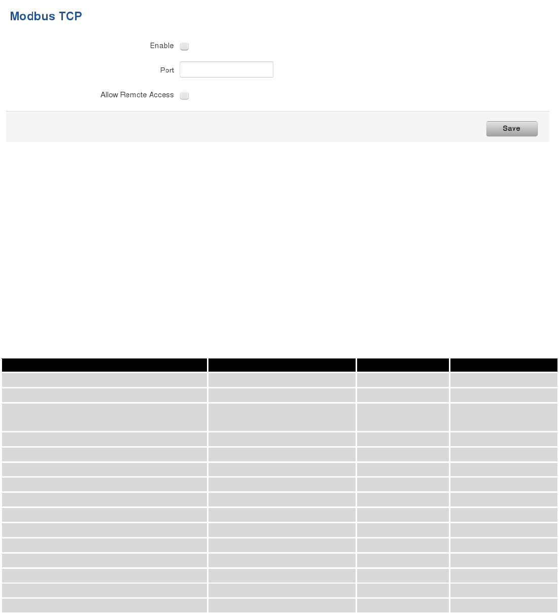
139
9.16 Modbus TCP interface
Modbus TCP interface allows the user to set or get some parameters from the router (the parameters, which can
be set or get will be described later), like module temperature or signal strength. In other words, Modbus TCP is another
manner to control router behavior. To use Modbus TCP capabilities it must be turned on by navigating to Services-
Modbus. After “Save” button is pressed, the Modbus daemon will be launched on selected port of the system. Modbus
daemon performs as slave, that means, it accepts connection from the master (client) and sends out a response or sets
some system related parameter. By the default Modbus will only accept connections through LAN interface. In order to
accept connections through WAN interface also, Allow Remote Access must be checked.
To obtain some parameter from the system, the read holding registers command is used. The register number
and corresponding system values are described below. Each register contains 2 bytes. For simplification the number of
registers for storing numbers is 2, while for storing text information the number of registers is 16.
Required value
Representation
Register number
Number of registers
System uptime
32 bit unsigned integer
1
2
GSM signal strength (dBm)
32 bit integer
2
2
System temperature in 0.1 degrees
Celcium
32 bit integer
3
2
System hostname
Text
4
16
GSM operator name
Text
5
16
Router serial number
Text
6
16
Router MAC address
Text
7
16
Router name
Text
8
16
Current SIM card
Text
9
16
Network registration
Text
10
16
Network type
Text
11
16
Digital input 1
32 bit integer
12
2
Digital input 2
32 bit integer
13
2
Current WAN IP address
32 bit unsigned integer
14
2
Analog input
32 bit integer
15
2
The Modbus daemon also supports setting of some system parameters. For this task write holding register
command is used. System related parameters and how to use them are described below. The register number refers to
the register number where to start write required values. All commands, except “Change APN” accepts only one input
parameter. For the APN the number of input registers may vary. The very first byte of APN command denotes a number
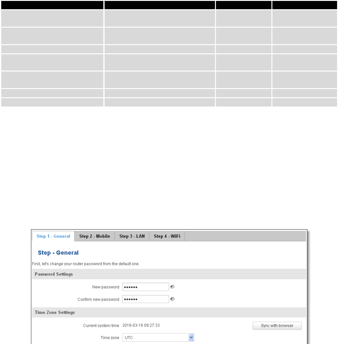
140
of SIM card for which set the APN. This byte should be set to 1 (in order to change APN for SIM card number 1) or to 2
(in order to change APN for SIM card number 2).
Value to set
Description
Register number
Register value
Digital output 1 (on/off)
Change the state of the digital output
number 1
1
1/0
Digital output 2 (on/off)
Change the state of the digital output
number 2
2
1/0
Switch WiFi (on/off)
Allows to switch WiFi on or off
10
1/0
Switch mobile data connection
(on/off)
Turns on or off mobile data
connection
11
1/0
Switch SIM card (SIM1, SIM2,
SIM1->SIM2 and SIM2->SIM1)
Allows to change SIM card in use, 3
possible options are supported
12
0/1/2
Change APN
Allows to change APN
13
APN code
Reboot
Reboots a router
20
1
10 System
10.1 Setup Wizard
The configuration wizard provides a simple way of quickly configuring the device in order to bring it up to basic
functionality. The wizard is comprised out of 4 steps and they are as follows:
Step 1 (General change)
First, the wizard prompts you to change the default password. Simply enter the same password into both
Password and Confirmation fields and press Next.
Step 2 (Mobile Configuration)
Next we have to enter your mobile configuration. On a detailed instruction on how this should be done see the
Mobile section under Network
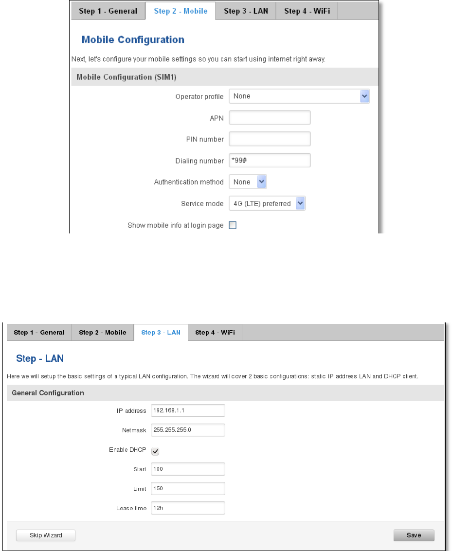
141
Step 3 (LAN)
Next, you are given the chance to configure your LAN and DHCP server options. For a detailed explanation see
LAN under Network.
Step 4 (Wi-Fi)
The final step allows you to configure your wireless settings in order to set up a rudimentary Access Point.
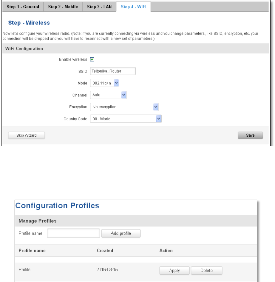
142
When you’re done with the configuration wizard, press Save.
10.2 Profiles
Router can have 5 configuration profiles, which you can later apply either via WebUI or via SMS. When you add
New Profile, you save current full configuration of the router. Note: profile names cannot exceed 10 symbols.
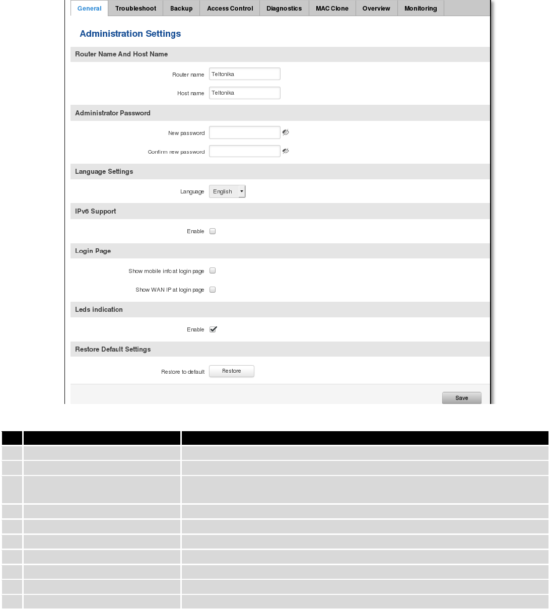
143
10.3 Administration
10.3.1 General
Field name
Explanation
1.
Router name
Enter your new router name.
2.
Host name
Enter your new host name
3.
New Password
Enter your new administration password.
Changing this password will change SSH password as well.
4.
Confirm new password
Re-enter your new administration password.
5.
Language
Website will be translated into selected language.
6.
IPv6 support
Enable IPv6 support on router
7.
Show mobile info at login page
Show operator and signal strength at login page.
8.
Show WAN IP at login page
Show WAN IP at login page.
9
On/Off LEDs
If uncheck, all routers LEDs are off.
10
Restore to default
Router will be set to factory default settings
Important notes:
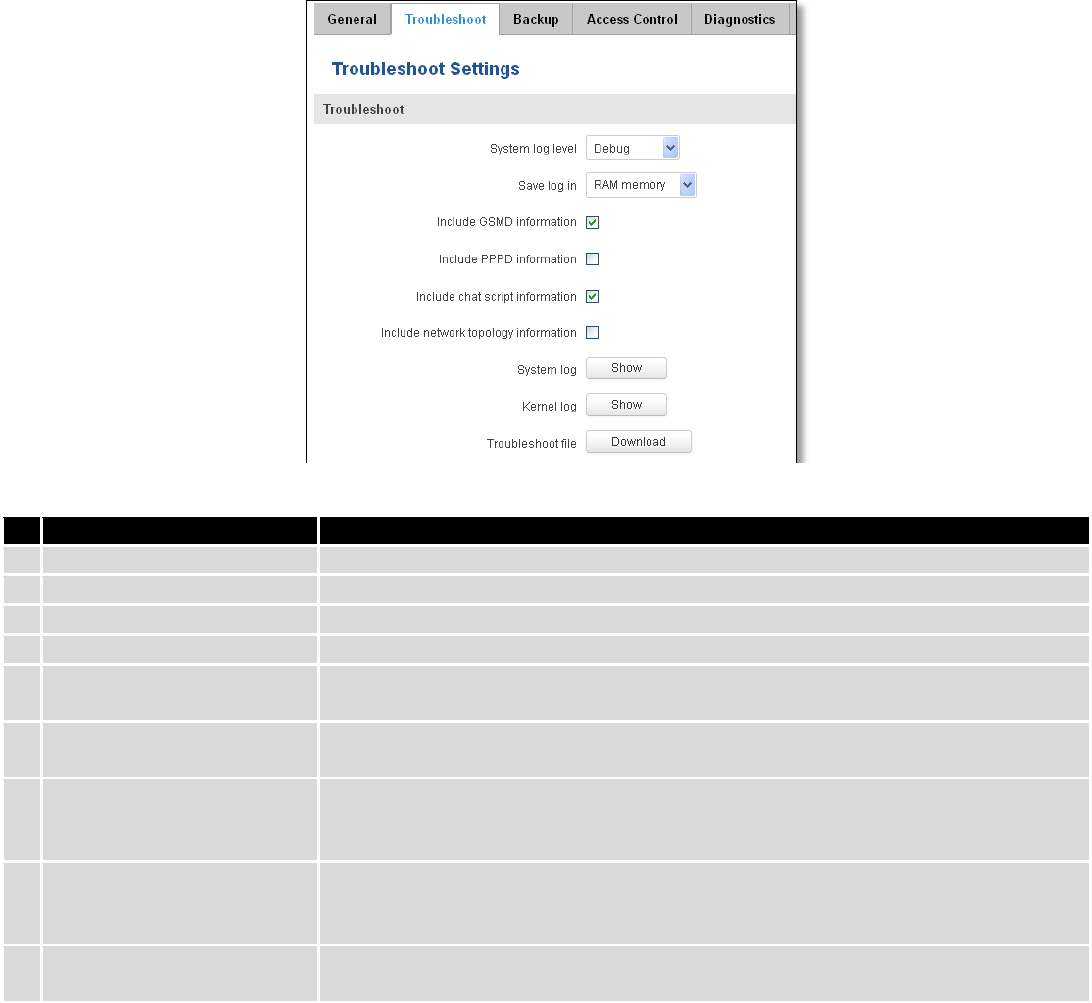
144
The only way to gain access to the web management if you forget the administrator password is to reset the
device factory default settings. Default administrator login settings are:
User Name: admin
Password: admin01
10.3.2 Troubleshoot
Field name
Explanation
1.
System log level
Debug level should always be used, unless instructed otherwise.
2.
Save log in
Default RAM memory should always be used unless instructed otherwise.
3.
Include GSMD information
Default setting – enabled should be used, unless instructed otherwise.
4.
Include PPPD information
Default setting – disabled should be used, unless instructed otherwise.
5.
Include Chat script
information
Default setting – enabled should be used, unless instructed otherwise.
6.
Include network topology
information
Default setting – disabled should be used, unless instructed otherwise.
7.
System Log
Provides on-screen System logging information. It does not, however, substitute
troubleshooting file that can be downloaded from System -> Backup and Firmware
menu.
8.
Kernel Log
Provides on-screen Kernel logging information. It does not, however, substitute
troubleshooting file that can be downloaded from System -> Backup and Firmware
menu.
9.
Troubleshoot file
Downloadable archive, that contains full router configuration and all System log
files.
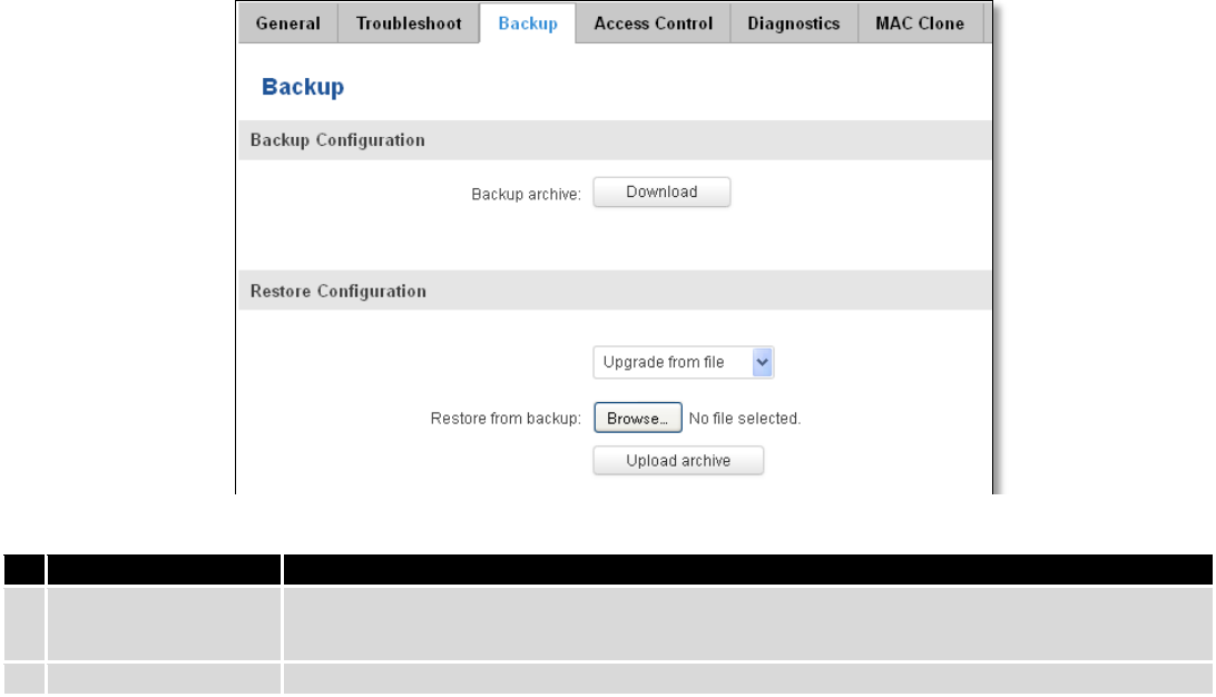
145
10.3.3 Backup
Field name
Explanation
1.
Backup archive
Download current router settings file to personal computer. This file can be loaded to
other RUT950 with same Firmware version in order to quickly configure it.
2.
Restore from backup
Select, upload and restore router settings file from personal computer.
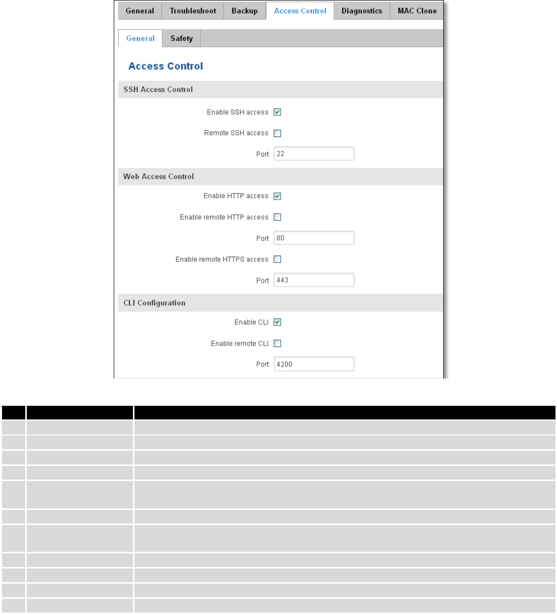
146
10.3.3.1 Access control
10.3.3.1.1 General
Field name
Explanation
1.
Enable SSH access
Check box to enable SSH access.
2.
Remote SSH access
Check box to enable remote SSH access.
3.
Port
Port to be used for SSH connection
4.
Enable HTTP access
Enables HTTP access to router
5.
Enable remote HTTP
access
Enables remote HTTP access to router
6.
Port
Port to be used for HTTP communication
7.
Enable remote
HTTPS access
Enables remote HTTPS access to router
8.
Port
Port to be used for HTTPS communication
9.
Enable CLI
Enables Command Line Interface
10.
Enable remote CLI
Enables remote Command Line Interface
11.
Port
Port to be used for CLI communication
Note: The router has 2 users: “admin” for WebUI and “root” for SSH. When logging in via SSH use “root”.
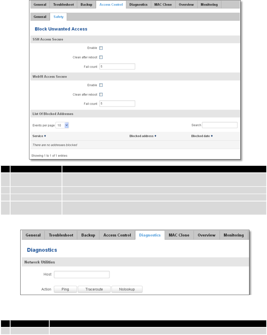
147
10.3.3.1.2 Safety
Field name
Explanation
1.
SSH access secure
enable
Check box to enable SSH access secure functionality.
2.
Clean after reboot
If check box is selected – blocked addresses are removed after every reboot.
3.
Fail count
Specifies maximum connection attempts count before access blocking.
4.
WebUI access
secure enable
Check box to enable secure WebUI access.
10.3.4 Diagnostics
Field name
Explanation
1.
Host
Enter server IP address or hostname.
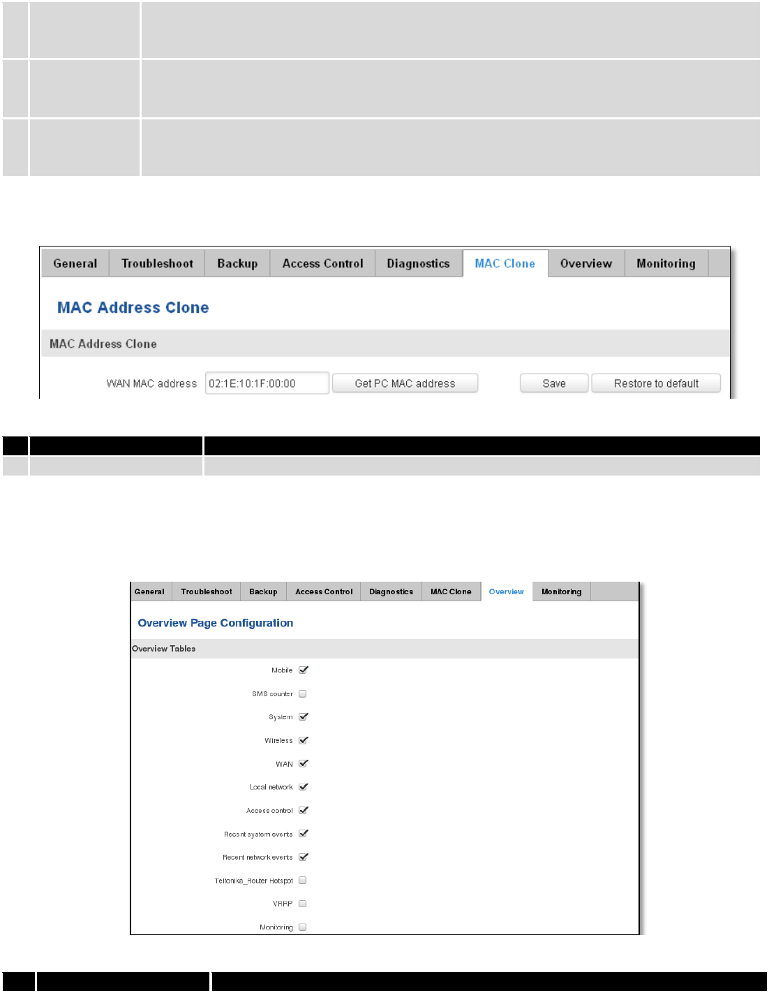
148
2.
Ping
Utility used to test the reach ability of a host on an Internet IP network and to measure the
round-trip time for messages sent from the originating host to a destination server. Server echo
response will be shown after few seconds if server is accessible.
3.
Traceroute
Diagnostics tool for displaying the route (path) and measuring transit delays of packets across an
Internet IP network. Log containing route information will be shown after few seconds.
4.
Nslookup
Network administration command-line tool for querying the Domain Name System (DNS) to
obtain domain name or IP address mapping or for any other specific DNS record. Log containing
specified server DNS lookup information will be shown after few seconds.
10.3.5 MAC Clone
Field name
Explanation
1.
WAN MAC address
Enter new WAN MAC address.
10.3.6 Overview
Select which information you want to get in Overview window (Status -> Overview).
Field name
Explanation
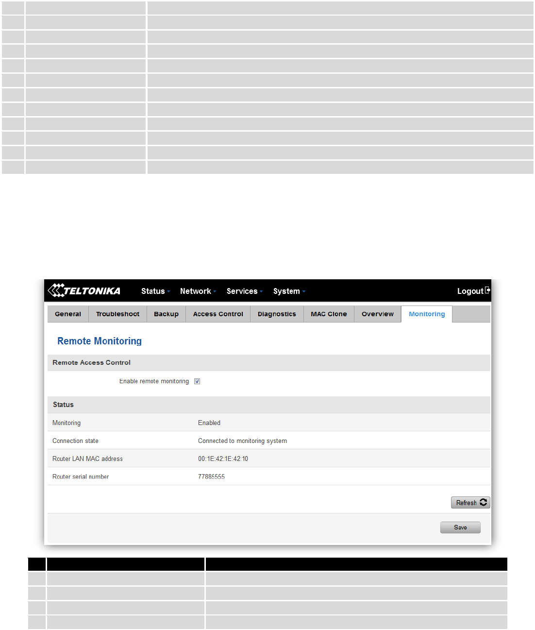
149
1.
Mobile
Check box to show Mobile table in Overview page
2.
SMS counter
Check box to show SMS counter table in Overview page
3.
System
Check box to show System table in Overview page
4.
Wireless
Check box to show Wireless table in Overview page
5.
WAN
Check box to show WAN table in Overview page
6.
Local network
Check box to show Local network table in Overview page
7.
Access control
Check box to show Access control table in Overview page
8.
Recent system events
Check box to show Recent system events table in Overview page
9.
Recent network events
Check box to show Recent network events table in Overview page
10.
<Hotspot name> Hotspot
Check box to show Hotspot instance table in Overview page
11.
VRRP
Check box to show VRRP table in Overview page
12.
Monitoring
Check box to show Monitoring table in Overview page
10.3.7 Monitoring
Monitoring functionality allows your router to be connected to Remote Monitoring System. Also MAC
address and router serial numbers are displayed for convenience in this page, because they are needed when
adding device to monitoring system.
Field name
Explanation
1.
Enable remote monitoring
Check box to enable/disable remote monitoring
2.
Monitoring
Shows monitoring status.
3.
Router LAN MAC address
MAC address of the Ethernet LAN ports
4.
Router serial number
Serial number of the device
10.4 User scripts
Advanced users can insert their own commands that will be executed at the end of booting process.
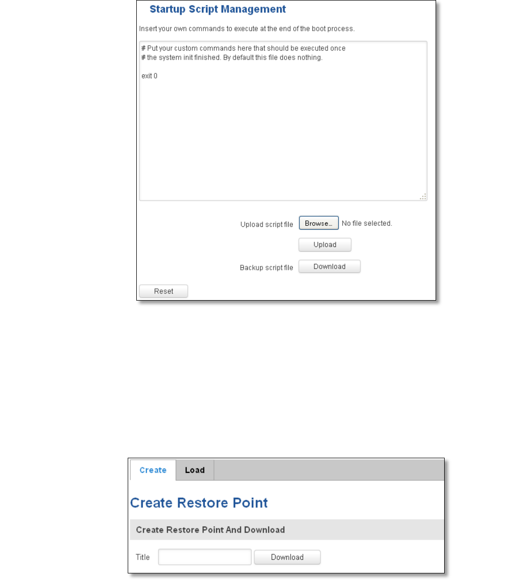
150
In Script Management window is shown content of a file /etc/rc.local. This file is executed at the end of startup,
executing the line: sh /etc/rc.local In this script is needed to use sh (ash) commands. It should be noted, that this is
embedded device and sh functionality is not full.
10.5 Restore point
10.5.1 Restore point create
Allow to create firmware restore points with all custom configurations. You can download created restore points
to your computer.
10.5.2 Restore point load
Allow to restore configuration from previously saved restore point. You can upload restore point from your
computer.
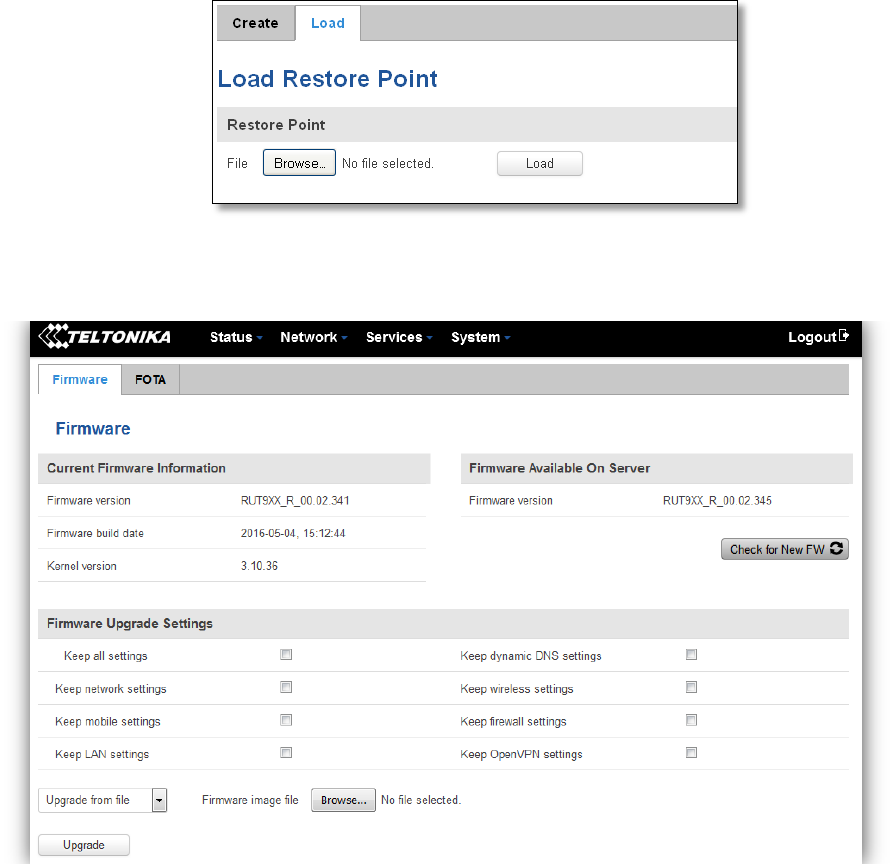
151
10.6 Firmware
10.6.1 Firmware
Keep all settings – if the check box is selected router will keep saved user configuration settings after firmware
upgrade. When check box is not selected all router settings will be restored to factory defaults after firmware upgrade.
When upgrading firmware, you can choose settings that you wish to keep after the upgrade. This function is useful
when firmware is being upgraded via Internet (remotely) and you must not lose connection to the router afterwards.
FW image – router firmware upgrade file.
Warning: Never remove router power supply and do not press reset button during upgrade process! This would
seriously damage your router and make it inaccessible. If you have any problems related to firmware upgrade you
should always consult with local dealer.
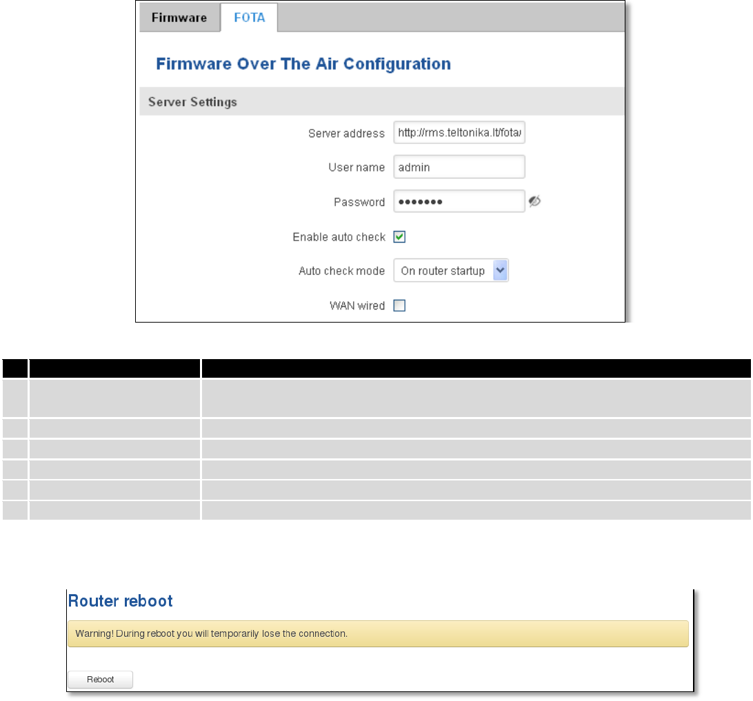
152
10.6.2 FOTA
Field name
Explanation
1.
Server address
Specify server address to check for firmware updates. E.g.
“http://teltonika.sritis.lt/rut9xx_auto_update/clients/”
2.
User name
User name for server authorization.
3.
Password
Password name for server authorization.
4.
Enable auto check
Check box to enable automatic checking for new firmware updates.
5.
Auto check mode
Select when to perform auto check function.
6.
WAN wired
Allows to update firmware from server only if routers WAN is wired (if box is checked).
10.7 Reboot
Reboot router by pressing button “Reboot”.

153
11 Device Recovery
The following section describes available options for recovery of malfunctioning device. Usually device can
become unreachable due to power failure during firmware upgrade or if its core files were wrongly modified in the file
system. Teltonika’s routers offer several options for recovering from these situations.
11.1 Reset button
Reset button is located on the back panel of the device. Reset button has several functions:
Reboot the device. After the device has started and if the reset button is pressed for up to 4 seconds the device
will reboot. Start of the reboot will be indicated by flashing of all 5 signal strength LEDs together with green connection
status LED.
Reset to defaults. After the device has started if the reset button is pressed for at least 5 seconds the device will
reset all user changes to factory defaults and reboot. To help user to determine how long the reset button should be
pressed, signal strength LEDs indicates the elapsed time. All 5 lit LEDs means that 5 seconds have passed and reset
button can be released. Start of the reset to defaults will be indicated by flashing of all 5 signal strength LEDs together
with red connection status LED. SIM PIN on the main SIM card is the only user parameter that is kept after reset to
defaults.
11.2 Bootloader’s WebUI
Bootloader also provides a way to recover the router functionality when the firmware is damaged. To make it
easier to use bootloader has its own webserver that can be accessed with any web browser.
Procedure for starting bootloader’s webserver:
Automatically. It happens when bootloader does not detect master firmware. Flashing all 4 Ethernet LEDs
indicate that bootloader’s webserver has started.
Manually. Bootloader’s webserver can be requested by holding reset button for 3 seconds while powering the
device on. Flashing all 4 Ethernet LEDs indicates that bootloader’s webserver has started.
Bootloader’s WebUI can be accessed by typing this address in the web browser:
http://192.168.1.1/index.html
Note: it may be necessary to clear web browser’s cache and to use incognito/anonymous window to access
bootloader’s WebUI.

154
12 Glossary
WAN – Wide Area Network is a telecommunication network that covers a broad area (i.e., any network that links
across metropolitan, regional, or national boundaries). Here we use the term WAN to mean the external network that
the router uses to reach the internet.
LAN – A local area network (LAN) is a computer network that interconnects computers in a limited area such as a
home, school, computer laboratory, or office building.
DHCP – The Dynamic Host Configuration Protocol (DHCP) is a network configuration protocol for hosts on Internet
Protocol (IP) networks. Computers that are connected to IP networks must be configured before they can communicate
with other hosts. The most essential information needed is an IP address, and a default route and routing prefix. DHCP
eliminates the manual task by a network administrator. It also provides a central database of devices that are connected
to the network and eliminates duplicate resource assignments.
ETHERNET CABLE – Refers to the CAT5 UTP cable with an RJ-45 connector.
AP – Access point. An access point is any device that provides wireless connectivity for wireless clients. In this
case, when you enable Wi-Fi on your router, your router becomes an access point.
DNS – Domain Name System. A server that translates names such as www.google.lt to their respective IPs. In
order for your computer or router to communicate with some external server it needs to know it’s IP, its name
“www.something.com” just won’t do. There are special servers set in place that perform this specific task of resolving
names into IPs, called Domain Name servers. If you have no DNS specified you can still browse the web, provided that
you know the IP of the website you are trying to reach.
ARP – Short for Adress Resolution Protocol a network layer protocol used to convert an IP address into a physical
address (called a DLC address), such as an Ethernet address.
PPPoE – Point-to-Point Protocol over Ethernet. PPPoE is a specification for connecting the users on an Ethernet to
the internet through a common broadband medium, such as DSL line, wireless device or cable modem.
DSL – digital subscriber line - it is a family of technologies that provide internet access by transmitting digital data
using a local telephone network which uses the public switched telephone network.
NAT – network address translation – an internet standard that enables a local-area network (LAN) to use one set
of IP addresses for internet traffic and a second set of addresses for external traffic.
LCP – Link Control Protocol – a protocol that is part of the PPP (Point-to-Point Protocol). The LCP checks the
identity of the linked device and either accepts or rejects the peer device, determines the acceptable packet size for
transmission, searches for errors in configuration and can terminate the link if the parameters are not satisfied.
BOOTP – Bootstrap Protocol – an internet protocol that enables a diskless workstation to discover its own IP
address, the IP address of a BOOTP server on the network, and a file to be loaded into memory to boot the machine.
This enables the workstation to boot without requiring a hard or floppy disk drive.
TCP – Transmission Control Protocol – one of the main protocols in TCP/IP networks. Whereas the IP protocol
deals only with packets, TCP enables two hosts to establish a connection and exchange streams of data. TCP guarantees
delivery of data and also guarantees that packets will be delivered in the same order in which they were sent.
155
TKIP – Temporal Key Integrity Protocol – scrambles the keys using hashing algorithm and, by adding an integrity-
checking feature, ensure that the keys haven’t been tampered with.
CCMP – Counter Mode Cipher Block Chaining Message Authentication Code Protocol – encryption protocol
designed for Wireless LAN products that implement the standards of the IEEE 802.11i amendment to the original
IEEE802.11 standard. CCMP is an enchanted data cryptographic encapsulation designed for data confidentiality and
based upon the Counter Mode with CBC-MAC (CCM) of the AES (Advanced Encryption Standard) standard.
MAC – Media Access Control. Hardware address which uniquely identifies each node of the network. In IEEE 802
networks, the Data Link Control (DCL) layer of the PSO Reference Model is divided into two sub-layers: the Logical Link
Control (LLC) layer and the Media Access Control layer. The MAC layer interfaces directly with the network medium.
Consequently, each different type of network medium requires a different MAC layer.
DMZ – Demilitarized Zone – a computer or small subnetwork that sits between a trusted internal network, such as
a corporate private LAN, and an untrusted external network, such as the public internet.
UDP – User Datagram Protocol – a connectionless protocol that, like TCP, runs on top of IP networks. Provides
very few error recovery services, offering instead a direct way to send and receive datagrams over IP network.
VPN – Virtual Private Network – a network that is constructed by using public wires — usually the Internet — to
connect to a private network, such as a company's internal network.
VRRP – Virtual Router Redundancy Protocol - an election protocol that dynamically assigns responsibility for one
or more virtual router(s) to the VRRP router(s) on a LAN, allow several routers on a multiaccess link to utilize the same
virtual IP address.
GRE Tunnel – Generic Routing Encapsulation - a tunneling protocol developed by Cisco Systems that can
encapsulate a wide variety of network layerprotocols inside virtual point-to-point links over an Internet Protocol
internetwork.
PPPD – Point to Point Protocol Daemon – it is used to manage network connections between two nodes on Unix-
likeoperating systems. It is configured using command-line arguments and configuration files.
SSH – Secure Shell - a program to log into another computer over a network, to execute commands in a remote
machine, and to move files from one machine to another. It provides strong authentication and secure communications
over insecure channels.
VRRPD – Virtual Router Redundancy Protocol – it is designed to eliminate the single point of failure associated
with statically routed networks by automatically providing failover using multiple LAN paths through alternate routers.
SNMP – Simple Network Management Protocol - a set of protocols for managing complex networks. SNMP works
by sending messages, called protocol data units (PDUs), to different parts of a network.

156
13 Changelog
Nr.
Date
Version
Comments
1
2017-02-01
1.34
2
2017-08-03
1.36
Page 2
3
2017-08-31
1.4