UBS Axcera CU150BTD 150-Watt UHF Digital Transmitter User Manual 5
UBS-Axcera 150-Watt UHF Digital Transmitter 5
UserManual.wiki
>
UBS Axcera
>
CU150BTD User Manual
>
User manual 5
Contents
1.
User manual 1
2.
User manual 2
3.
User manual 3
4.
User manual 4
5.
User manual 5
User manual 5
Navigation menu
Upload a User Manual
Namespaces
Wiki Guide
HTML
PDF
Info
Views
User Manual
Discussion / Help
Navigation

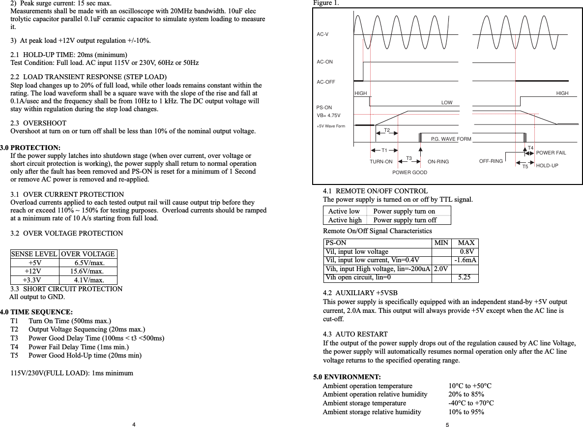
![23[Applicable only to models designed for sale in the European Union: TruePower models designed for the EU include Power Factor Correction (PFC) circuitry in accord with European standard regulation code EN61000-3-2. By altering the input current waveshape, PFC improves the power factor of the power supply and results in increased energyefficiency, reduced heat loss, prolonged life for power distribution and consumption equipment, and improved output voltage stability.]Installation:Note (not applicable to models designed for the European Union): Check the red power supply voltage switch setting before installation. It should be the same as your localpower voltage (115V for North America, Japan, etc. and 230V for Europe and many othercountries). Change the voltage setting if necessary. Failure to take this precaution couldresult in damage to your equipment and could void your warranty.1. Disconnect the power cord from your old power supply.2. Follow your computer case manual and open the case.3. Disconnect all the power Connectors from the motherboard and from the peripheral devices such as case fans, hard drives, floppy drives, etc.4. Remove the existing power supply from your computer case and replace it with the Antec power supply.5. Connect the Power Connectors to your motherboard and peripheral devices.6. Connect the case fans to the dedicated fan connectors.Note: Do not connect other devices except fans to these connectors. You may connect case fans to the regular 4-pin Peripheral connectors if you choose not to utilize TruePower Circuitry on your case fans.7. Connect the 3-pin fan signal connector to one of the fan connectors on your motherboard.Note: You do not need to connect the 3-pin fan signal connector in order to make the power supply work if you choose not to monitor the speed of the fan.8. Close the computer case. 9. Connect the power cord to the Antec power supplySpecifications:1.0 INPUT:1.1. VOLTAGE1.2 FREQUENCY47Hz ~ 63Hz1.3 CURRENT1.4 INRUSH CURRENT115V/50A(max.), 230V/80A(max.) at 25°C cold start1.5 POWER EFFICIENCY68% (min.) at full load, 115/230Vac 60Hz/50Hz2.0 OUTPUT:Note:1) The continuous maximum total output power RANGE MINIMUM NOMINAL MAXIMUM UNITS1 90 115 135 VRMS2 180 230 265 VRMS115V 230VTRUE330 7A 4ATRUE380 8A 5ATRUE430 9A 5ATRUE480 12A 6ATRUE550 12A 6AVOLTAGE +5V +12V +3.3V -5V -12V +5VSBMAX. LOADTRUE330 30A 17A 28A 0.5A 1.0A 2.0ATRUE380 35A 18A 28A 0.5A 1.0A 2.0ATRUE430 36A 20A 28A 0.5A 1.0A 2.0ATRUE480 38A 22A 30A 1.5A 1.0A 2.0ATRUE550 40A 24A 32A 0.5A 1.0A 2.0AMIN. LOAD 0A 0.8A 0A 0A 0A 0AREGULATION ±3% ±3% ±3% ±5% ±5% ±5%RIPPLE & NOISE 50 120 50 50 120 50(mV)TOTAL MAX. +5V,+12V & +3.3VOUTPUT MAX. OUTPUTTRUE330 330W 310WTRUE380 380W 360WTRUE430 430W 410WTRUE480 480W 460WTRUE550 550W 530WTRUE330TRUE380TRUE430TRUE330TRUE380 TRUE430TRUE330TRUE380 TRUE430](https://usermanual.wiki/UBS-Axcera/CU150BTD.User-manual-5/User-Guide-1145893-Page-3.png)