UBS Axcera LU100AL 100-Watt UHF Translator User Manual 366898
UBS-Axcera 100-Watt UHF Translator 366898
Contents
Chapter 5

10W-100W UHF Translator Chapter 5, Detailed Alignment Procedures
Pioneer, UHF Translator, Rev. 0 5-1
Chapter 5
Detailed Alignment Procedures
This translator was aligned at the factory
and should not require additional
adjustments to achieve normal operation.
This translator takes the On channel RF
input to the Receiver Tray and converts it
to the desired UHF On Channel RF Output
at the systems output power level.
If the (Optional) Modulator Kit is
purchased, this translator can also
operate using the baseband audio and
video inputs or, if the (Optional) 4.5-MHz
composite input kit is purchased, either a
single composite video + 4.5-MHz input
or separate baseband video and audio
inputs.
The exciter/amplifier of the Pioneer
Series translator is of a Modular design
and when a Module fails that module
needs to be changed out with a
replacement module. The replacement
module can then be sent back to Axcera
for repair. Contact Axcera Customer
Service Department at 724-873-8100 or
fax to 724-873-8105, before sending in
any module.
Module Replacement
Module replacement on the Pioneer
series products is a relatively simple
process. All modules plug directly into
the backplane board except for the
power amplifier module, and in higher
power units, the power supply and
power amplifier modules, that plug into
a blind mating connector. To replace a
module, refer to the following
procedure.
Loosen the two grip lock connectors,
located on the front panel, at the top
and bottom of the module,
counterclockwise until the module
releases. The IF Processor, Upconverter
and Controller/Power Supply can then
be gently pulled from the unit. There
are two cables connected to the rear of
the Power Amplifier Module in the
exciter/amplifier chassis assembly.
These two cables must first be removed
before the PA module will slide out.
Slide the new module in place and make
certain it connects to the backplane
board. If the new module is a PA
Module replace the two cables on the
rear of the exciter/amplifier chassis
assembly. If the new module does not
slide in easily, verify it is properly
aligned in the nylon tracks both top and
bottom.
Note: Each Module has an assigned slot
and will not fit properly in the incorrect
slot. Do not try to place a Module in the
wrong slot as this may damage the slot
or the connectors on the backplane
board.
Each module has the name of the
module on the front, bottom for
identification and correct placement.
The Modules are placed in the unit from
left to right; (1) Blank panel, (2)
Modulator (for transmitters) or a Blank
panel for a Translator, (3) IF Processor,
(4) Upconverter, (5) Controller/Power
Supply and (6) Power Amplifier.
Initial Test Set Up
Check that the RF output at the coupler
is terminated into a dummy load of at
least 100 watts. While performing the
alignment, refer to the Test Data Sheet
for the translator and compare the final
readings from the factory with the
readings on each of the modules or tray.
The readings should be very similar. If a
reading is way off, the problem is likely
to be in that module or tray.
Switch On both the main AC for the
system and the ON/OFF circuit breaker
located on the rear of the Receiver Tray.

10W-100W UHF Translator Chapter 5, Detailed Alignment Procedures
Pioneer, UHF Translator, Rev. 0 5-2
5.1 UHF/VHF Receiver Tray.
(1142479 or 1265-1100)
Connect a UHF or VHF Input that is at the
desired Channel Frequency, to J1 50Ω or
J5 75Ω located on the rear of the (A7)
VHF/UHF Receiver Tray. Check that the
On/Off Switch located on the rear of the
Tray is On.
Note: If the Red LED, DS1 is lit, +12
VDC is present at the input of the
Receiver Tray and may damage any test
equipment connected to it. Remove the
fuse F1, DS1 will not be lit, before
connecting test equipment to the input
jack of the Receiver Tray.
5.1.1 (A7) UHF Filter, DC
Multiplexed (1035-1204, 50
Ω
or
1035-1207, 75
Ω
), VHF Filter, LB, DC
Multiplexed (1035-1902, 50
Ω
or
1035-1903, 75
Ω
) or VHF Filter, HB,
DC Multiplexed (2065-1024, 50
Ω
or
2065-1023, 75
Ω
)
The input UHF or VHF signal (-61 dBm to
-16 dBm) is fed to the filter which has
been factory swept for 6 MHz Bandwidth
at the Channel frequency and should not
be tuned in the field. The output of the
filter is directed to the J1 input of (A8)
the Dual Stage Amplifier Assembly.
5.1.2 (A8-A1) Dual Stage Amplifier
Board (1227-1501)
Mounted in: (A8) a Dual Stage Amplifier
Assembly (1227-1503).
The Dual Stage Amplifier Board has been
factory set to the channel frequency and
contains no customer tuning
adjustments. The board has
approximately +13 dB or +26 dB of gain,
depending on whether Jumper W1 on J5
is in place.
5.1.3 (A9) UHF Filter (1007-1101),
VHF LB Filter (1034-1202) or VHF
HB Filter (2065-1000)
The UHF or VHF Filter has been factory
swept for 6 MHz Bandwidth at the
Channel Frequency and should not be
tuned in the field. The output of the filter
(-50 dBm to -5 dBm) is fed either
through the additional amplifier stage on
the Variable Gain Amplifier Board or to
(A10-A1) the Downconverter/Filter
Board.
5.1.4 (A4) Channel Oscillator
Assembly, Dual Oven (1145-1202)
Contains: The Channel Oscillator Board,
Dual Oven (1145-1201).
1. Connect the main output of the
Channel Oscillator (J1) to a
spectrum analyzer, adjusted to
view the crystal frequency.
Peak the tuning capacitors C6 and
C18 for maximum output. Then
tune L2 and L4 for maximum
output. The output level should
be approximately +5 dBm and the
Oven Temperature should be
maintained at 50°C.
If a spectrum analyzer is not
available, connect a DVM to TP1
on the x8, x4 or x2 Multiplier
Board. Tune capacitors C6 and
C18 for maximum voltage at TP1.
Then tune L2 and L4 for maximum
voltage at TP1.
2. Connect the sample output of the
Channel Oscillator at J2 to a
suitable counter and tune C11,
Coarse Adjust, and C9, Fine
Adjust, to the crystal frequency.
Do not re-peak C6, C18, L2 or L4
because this may change the
output frequency.
Note: While adjusting C9 and C11 to the
crystal frequency the peak voltage
monitored at TP1 of the Multiplier
Board should not decrease. If a
decrease does occur a problem
with the crystal is likely.
3. Reconnect the main output at J1
of the Channel Oscillator to the
Input Jack J1 of the Multiplier
Board.

10W-100W UHF Translator Chapter 5, Detailed Alignment Procedures
Pioneer, UHF Translator, Rev. 0 5-3
Note: If the Optional Frequency
Correction Kit is purchased a VCXO
Assembly (1145-1206), containing
a VCXO Board (1145-1204), will be
used instead of the standard
Channel Oscillator Board. The
adjustment will be the same as
above except that the frequency is
adjusted by moving the Jumper
W1 on Jack J6, located on the IF
PLL Board (1109-1002), to Pins 2
& 3, Fixed Bias, and adjusting R15
on the IF PLL Board for -3 VDC at
FL2 of the VCXO Assembly. Move
the Jumper W1 on Jack J6 to
between Pins 1 & 2, AFC. Connect
the Oscillator Sample output, at
(J2) of the Channel Oscillator or
the Front Panel Sample Jack (J9),
to a suitable Frequency Counter
and tune C11, Coarse Adjust, to
the desired frequency. Do not
re-peak C6, C18, L2 or L4 because
it may change the output
frequency.
Reconnect the main output (J1) of
the Channel Oscillator (+5 dBm) to
the input (J1) of the Multiplier
Board. DS1 the Red Unlock
Indicator, located on the IF PLL
Board, should not be lit.
5.1.5 (A5-A1) x8 Multiplier Board
(1227-1002), x4 Multiplier Board
(1227-1525) or x2 Multiplier Board
(1227-1524)
Mounted in (A5) a Multiplier Enclosure
(1265-1125).
During Normal operation, the Green LED
DS1, which can be seen through the
access hole in the Enclosure Assembly,
will be lit to indicate that the L.O. is
present at the output of the x8 Multiplier
Board.
1. Connect a Spectrum Analyzer to
the Output Jack (J2) of the board.
2. Tune C4, C6, C10, C12, C18 and
C20 on the x8 and the appropriate
caps on the other boards for
maximum output. Readjust all the
Capacitors to minimize the
seventh and the ninth harmonics,
they should be at least -30 dB
down, without affecting the x8
Multiplier Output.
If a Spectrum Analyzer is not available a
DC voltmeter can be used as follows but
the harmonic frequencies must be
minimized to prevent interference with
other Channels.
1. While Monitoring each Test Point
with a DC voltmeter, maximize the
voltage by tuning the Broadband
Multipliers in the following
sequence.
2. For x8 Multiplier Board: Monitor
TP1 with a DVM and tune C4 for
maximum. (Typical .6 VDC)
Monitor TP2 and tune C6 and C10
for maximum. (Typical 1.2 VDC)
Monitor TP3 and tune C12 and C18
for maximum. (Typical 2 VDC)
Monitor TP4 and tune C20 for
maximum. Re-peak C12 and C10
while monitoring TP4. (Typical 3.5
VDC)
For x4 Multiplier: Monitor TP1 with
a DVM and tune C4 for maximum.
(Typical .6 VDC)
Monitor TP2 and tune C6 and C10
for maximum. (Typical 1.2 VDC)
Monitor TP3 and tune C12 for
maximum. Re-peak C12 and C10
while monitoring TP3. (Typical 2
VDC) For x2 Multiplier: Monitor
TP1 with a DVM and tune C4 for
maximum. (Typical .6 VDC)
Monitor TP2 and tune C6 for
maximum. Re-peak C4 and C6
while monitoring TP2. (Typical 1.2
VDC)
The Green LED DS1 should be lit which
indicates that the L.O. is present at the
Output Jack J2 of the Multiplier Board.
The output of the Multiplier at J2 is
connected to (A6) a UHF or VHF Filter.

10W-100W UHF Translator Chapter 5, Detailed Alignment Procedures
Pioneer, UHF Translator, Rev. 0 5-4
5.1.6 (A6) UHF Filter (1007-1101),
VHF LB Filter (1034-1211) or VHF
HB Filter (2065-1000)
This filter has been factory swept at the
L.O. frequency and should not be tuned
without proper equipment. The output of
the filter (+15 dBm) is connected to J2
on (A10) the Downconverter/Filter
Assembly.
5.1.7 (A10-A1) Downconverter/
Amplifier Board (1227-1502)
Mounted in: The (A10)
Downconverter/Amplifier Assembly
(1227-1505).
The Mixer contains no adjustments and
has a L.O. input of approximately +12
dBm in level applied to J2 and a -47 dBm
to -2 dBm RF input applied to J1. The
output IF level at J3 will be -55 dBm to
-10 dBm.
1. Connect a Spectrum Analyzer to
the Output Jack J3 and adjust L1,
C2 and L3 for best frequency
response.
2. Adjust C8 and R3 to notch out the
Aural IF Frequency.
The IF output at J3 (-55 dBm to -10
dBm) is fed to the IF Filter/ALC Board. If
needed a 10 dB Pad can be added to the
circuit by moving the jumpers on J4 and
J5 to the In position.
5.1.8 (A11-A1) IF Filter/ALC Board
(1227-1504) Mounted in: The (A11)
IF Filter/ALC Enclosure (1265-
1105).
1. Check that Switch S1, located on
the IF Filter/ALC Board, is in the Auto
ALC and that the output of the Board at
J2 is approximately 0 dBm Output, adjust
R23 if needed.
5.1.9 (A11-A2) (Optional) SAW
Filter/Amplifier Board (1035-1211)
Mounted in: The (A11) IF Filter/ALC
Enclosure (1265-1105).
This board is used for additional adjacent
Channel rejection only if needed and may
not be part of the Tray.
The board contains no tuning
adjustments. The Jumpers W1 and W2
on J4 and J5 are placed for Attenuator In
or Attenuator Out as needed to give the
same output level at J2 as was at J1.
5.1.10 (A2) ±12V Power Supply
Board (1092-1206)
This board contains no adjustments.
Note: If the (Optional) Frequency
Corrector Kit is part of the tray, perform
the following adjustments. If the
Frequency Corrector Kit is not part of the
tray, the tray is aligned and ready for
normal operation.
5.1.11 (A15) (Optional) IF Carrier
Oscillator Board (1100-1206)
1. Monitor J3 with a Spectrum
Analyzer and observe the 38.9
MHz Visual IF signal at +5 dBm.
2. Connect a Frequency Counter to J2
on the board or to J9 on the Front
Panel and adjust C17 for 38.9
MHz.
3. Connect a Frequency Counter to J1
and check for the 50 kHz signal.
Adjust C17, if needed, to attain
the 50 kHz frequency. Remove
the Jack on J5. DS2 the Unlock
Indicator should light. Replace the
Jack onto J5.
5.1.12 (A13) (Optional) IF Filter/
Limiter Board (1109-1001)
1. Monitor the Aural Notch Test
Output of the board at J5 and
move the Jumper W1 on Jack J4 to
between Pins 2 & 3, Test Position.
Adjust C17 to the Aural IF
Frequency, then adjust R10 to

10W-100W UHF Translator Chapter 5, Detailed Alignment Procedures
Pioneer, UHF Translator, Rev. 0 5-5
eliminate or minimize the Aural IF
signal. Move the Jumper W1 on
Jack J4 back to between Pins 1 &
2, Operate Position.
2. Monitor the IF CW Output of the
board at J6 with an Oscilloscope
and adjust R12 and C21 for
maximum Video Signal or connect
a Spectrum Analyzer, in Zero
Span, to J6 and adjust R12 and
C21 for Minimum Video Signal
amplitude ripple on the displayed
signal.
3. Adjust R15 for +3 dBm or
Maximum output level if +3 dBm
cannot be attained.
5.1.13 (A14) (Optional) IF PLL
Board (1109-1002)
Check that the Red LED DS1, Unlock
Indicator, located on the board is not lit.
If DS1 is lit, follow the alignment
procedure for setting up the VCXO
Channel Oscillator using R9 on the IF PLL
Board to set up the AFC Voltage for the
Frequency of the VCXO. If it is still lit,
check the 50 kHz reference output of the
(A15) IF Carrier Oven Oscillator. If
needed, follow the alignment procedure
for the IF Carrier Oven Oscillator Board.
5.1.14 (A16) (Optional) IF
Amplifier Board, High Gain (1197-
1126)
This board contains no customer
adjustments. The amplified IF output
from the IF Filter/ALC Board connects to
the IF Filter Limiter Board.
The Receiver Tray is now set up and
ready for normal operation.

10W-100W UHF Translator Chapter 5, Detailed Alignment Procedures
Pioneer, UHF Translator, Rev. 0 5-6
5.2 Pioneer Series Exciter/Amplifier
Chassis Assembly
The exciter/amplifier chassis assembly
operates using an external IF input from
an external receiver tray. The IF source
connects to J6, the modulated IF Input
jack, on the rear of the chassis assembly,
which is cabled to the IF Processor
Module.
On the LCD Display, located on the
Controller/Power Supply Module, push
the button to switch the translator to
Operate. The setup of the RF output
includes adjustments to the drive level of
the Power Amplifier, the adjustment of
the linearity and phase predistortion to
compensate for any nonlinear response
of the Power Amplifier on the front panel
of the IF Processor module.
Verify that all red LEDs located on the IF
Processor front panel are extinguished.
The following details the meaning of each
LED when illuminated:
• DS1 (input fault) – Indicates that
either abnormally low or no IF is
present at the input of the module.
• DS2 (ALC fault) – Indicates that the
ALC circuit is unable to maintain the
signal level requested by the ALC
reference. This is normally due to
excessive attenuation in the linearity
signal path or the IF phase corrector
signal path, or that switch SW1 is in
the Manual ALC Gain position.
• DS4 (Mute) – Indicates that a Mute
command is present to the system.
Switch the translator to Standby. The
ALC is muted when the translator is in
Standby. To monitor the ALC, preset R3,
manual gain adjust, on the front panel of
the Upconverter module, fully CCW.
Move switch SW1, Auto/Man AGC, on the
front panel of the Upconverter module, to
the Manual position. Place the translator
in Operate. Adjust the ALC GAIN pot on
the front panel of the IF Processor to
obtain +0.8 VDC on the LCD Display on
the Controller/Power Supply in the ALC
screen. Move the MAN/AUTO ALC switch
back to Auto, which is the normal
operating position.
To adjust the AGC Cutback setting, raise
the output power of the translator to
110%. Adjust R2, AGC Cutback, located
on the front panel, CCW until the LED
DS1, AGC Cutback, just starts to flash.
Return the output power of the translator
to 100%.
5.2.1 Linearity Correction
Adjustment
As shipped, the exciter was preset to
include amplitude and phase pre-
distortion. The pre-distortion was
adjusted to approximately compensate
the corresponding non-linear distortions
of the Power Amplifier.
NOTE: On the IF processor board inside
the module the correction enable/disable
jumper W12 on J30 will be in the Enable
position, on pins 2 & 3.
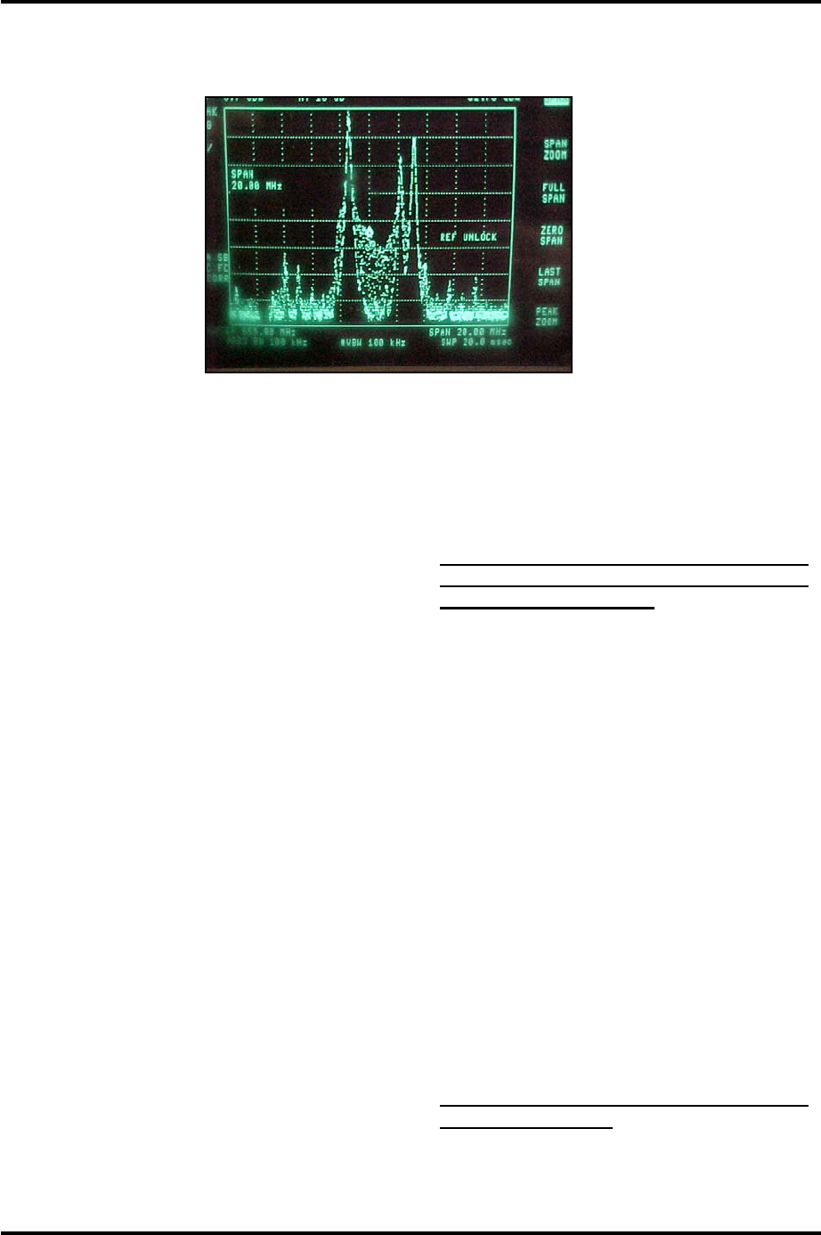
Set up a spectrum analyzer with 100 kHz
resolution bandwidth and 100 kHz video
bandwidth to monitor the
intermodulation products of the RF
output signal of the Power Amplifier. A
typical red field spectrum is shown in
Figure 5-1. There are three Linearity
Corrector stage adjustments located on
the front panel of the IF Processor
Module. The adjustments are threshold
settings that are adjusted as needed to
correct for any amplitude or phase
intermod problems. Adjust the top
linearity correction adjustment R211
threshold cut in for the in phase
amplitude distortion pre-correction that is
needed. Next adjust the middle linearity
correction adjustment R216 threshold cut
in also for the in phase amplitude
distortion pre-correction that is needed.
Finally adjust the bottom linearity
correction adjustment R231 threshold cut
in for the quadrature phase distortion
pre-correction that is needed. The above
10W-100W UHF Translator Chapter 5, Detailed Alignment Procedures
Pioneer, UHF Translator, Rev. 0 5-7
pots are adjusted for the greatest
separation between the peak visual
carrier and the intermod products.
Figure 5-1. Typical Red Field Spectrum
5.2.2 Frequency Response Delay
Equalization Adjustment
The procedure for performing a
frequency response delay equalization
adjustment for the translator is described
in the following steps:
The center frequency for the first stage is
46.5 MHz. Adjust R103, the top
frequency response equalizer pot, located
on the front panel of the IF Processor
Module, for the best depth of frequency
response correction at 46.5 MHz.
The center frequency for the second
stage is 41.5 MHz. Adjust R106, the
middle frequency response equalizer pot,
located on the front panel of the IF
Processor Module, for the best depth of
frequency response correction at 41.5
MHz.
The center frequency for the second
stage is 44 MHz. Adjust R274, the
bottom frequency response equalizer pot,
located on the front panel of the IF
Processor Module, for the best depth of
frequency response correction at 44 MHz.
After the three delay attenuation
equalizers have been adjusted, fine tune,
as needed, for the best frequency
response across the channel.
5.2.3 Calibration of Output Power
and Reflected Power of the
translator
Note: Perform the following
procedure only if the power
calibration is suspect.
Switch the transmitter to Standby and
preset R205, the aural null pot on the
Amp Control board, fully CCW. Adjust
R204, the null offset pot on the Amp
Control board, for 0% visual output.
Perform the following adjustments with
no aural present by removing the aural
carrier from the test modulator. Connect
a sync and black test signal to the video
input jack of the test modulator. Switch
the transmitter to Operate.
Next, set up the transmitter for the
appropriate average output power level:
• Sync + black 0 IRE
setup/wattmeter=59.5 watts
• Sync + black 7.5 IRE
setup/wattmeter=54.5 watts
Note: The transmitter must have 40
IRE units of sync.
Adjust R202, visual calibration, on the
Amp Control board for 100% on the front

10W-100W UHF Translator Chapter 5, Detailed Alignment Procedures
Pioneer, UHF Translator, Rev. 0 5-8
panel display in the % Visual Output
position.
With the spectrum analyzer set to zero
span mode, obtain a peak reference on
the screen. Reconnect the aural carrier
from the test modulator. Turn the power
adjust pot on the front panel until the
original peak reference level is attained.
Adjust R203 for a 100% aural power
reading. Switch to the Visual Output
Power position and adjust R205 (aural
null pot) for 100% visual power.
To calibrate the reflected output power
reading of the translator. Reduce manual
gain pot R3 to a 10% reading on the LCD
front panel display in the % Output
Power position. Place the translator in
Standby. Remove the load from J4 on
the (A4) Direction Coupler Board and
switch the LCD Display screen to the
Reflected Output Power position. Switch
the translator to operate. Adjust the
reflected power calibration adjust pot
R163 on the power amplifier module to a
10% reading. Reconnect the load to J4.
After this calibration is completed, move
switch SW1 on the upconverter module
to the Automatic AGC position. This is
the normal operating position for the
switch.
The Translator is now aligned, calibrated,
and ready for normal operation.
This completes the detailed alignment
procedures for the Pioneer Series
translator.
If a problem occurred during the
alignment, help can be found by calling
Axcera field support at 724-873-8100.
5.3 Alignment Procedure for the
Bandpass Filter Assembly
The Bandpass Filter Assembly is tuned to
reject unwanted distortion products
generated when the signals are diplexed
and also during the amplification process.
The Bandpass Filter is factory tuned to
the proper bandwidth and should not
need tuned. If you think tuning is
needed consult ITS Corp. Field Support
Department before beginning.
The Traps are labeled with their Center
Frequency relative to the Frequency of
the Carrier. (For Example: The Traps
labeled -4.5 MHz are tuned for a Center
Frequency of 4.5 MHz Lower than the
Frequency of the Visual Carrier.)
The Trap Sections are Reflective Notches,
adjustable across the entire UHF
Frequency Band. The electrical length of
the Outer Sleeve and the Center Rod of
the Notch can be adjusted to Tune the
Notch Frequency. The Depth of the
Notch is set by the gap between the
Center Conductor of the Trap Section and
the Center Conductor of the Main Line.
Tight Coupling makes a Deep Notch,
while Loose Coupling makes a Shallow
Notch.
The Trap Sections have been factory
tuned and should not need major
adjustments. The Frequency, relative to
Visual Carrier, that the Trap is tuned to is
marked on the Notch. Fine Tuning of the
Notches Center Frequency can be
accomplished with the Tuning Bolts
located on the side of the Filter Section.
Loosen the nut locking the Bolt in place
and adjust the Bolt to change the
Frequency of the Notch. Monitor the
output of the Transmitter with a
Spectrum Analyzer and Null the
Distortion Product with the Bolt. Red
Field is a good Video Test Signal to use to
see the +8.08 MHz Product. Tighten the
nut when the tuning is completed. Hold
the bolt in place with a screwdriver as
the nut is tightened to prevent it from
slipping.
For major tuning, such as changing the
Notch Depth or moving the Notch
Frequency more than 1 MHz, the Outer
Conductor and the Center Conductor of
the Trap Section must both be moved.
This requires an RF Sweep Generator to

10W-100W UHF Translator Chapter 5, Detailed Alignment Procedures
Pioneer, UHF Translator, Rev. 0 5-9
accomplish. Apply the Sweep signal to
the Input of the Trap Filter and monitor
the Output. Loosen the Clamp holding
the Outer Conductor in place and make
the length longer to Lower the frequency
of the Notch or shorter to Raise the
frequency of the Notch. Loosen the
Center Conductor with an Allen Wrench
and move it Deeper for a Lower
Frequency Notch or out for a Higher
Frequency Notch. These adjustments
must both be made to change the Notch
Frequency. Moving only the Center
Conductor or the Outer Conductor will
effect the Notch Depth in addition to the
Center Frequency. The variable that is
being adjusted with this procedure is the
length of the Center Conductor inside the
Trap Filter. The gap between the Trap
and the Main Line should not be changed.
Moving only the Inner or the Outer
Conductors by itself will effect the Gap
and the Notch depth.
To effect the Notch Depth Only, both
sections will have to be moved. The
Notch Depth is controlled by the Gap
between the Center Conductor and the
Trap Section. This Gap also has an effect
on the Center Frequency. To Deepen the
Notch, Shorten the Outer Conductor and
pull the Center Conductor Out until the
Notch is back in the same place. Move
the Sections in the opposite direction to
make a Shallow Notch.
After tuning has been completed, tighten
the Clamp and the Allen Screws which
hold the Conductors. Use the Fine
Tuning Bolts to bring the Frequency In.
The Final Tuning Adjustments should be
completed with the Transmitter driving
the Output Trap Filter for at least one
hour to allow for warm-up drift.
This completes the Alignment Procedure
for the Bandpass Filter Assembly.