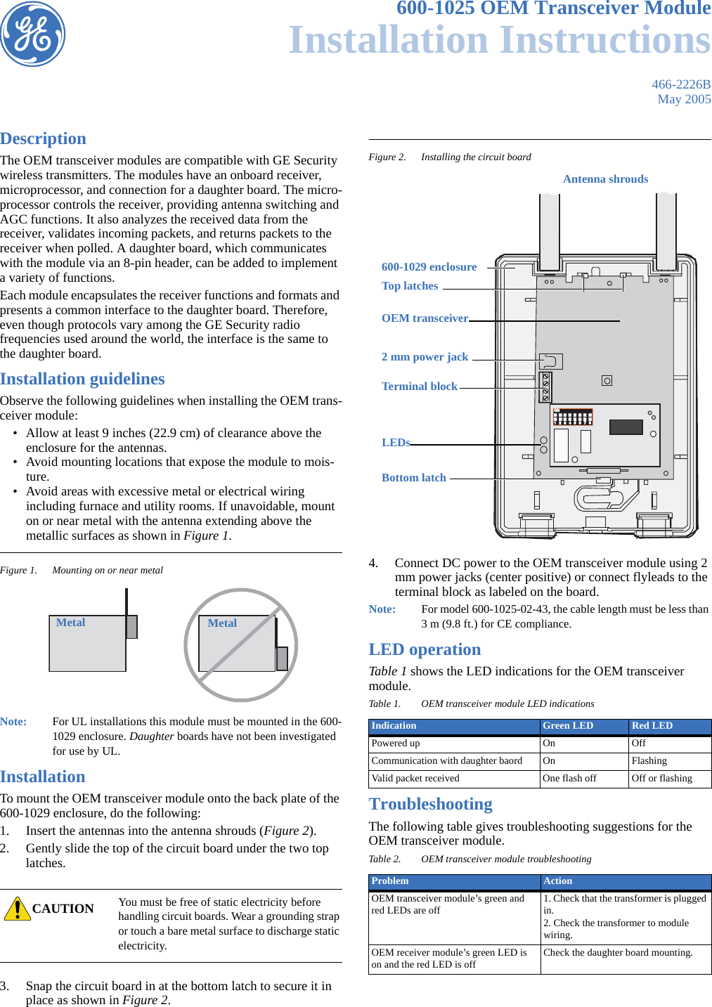
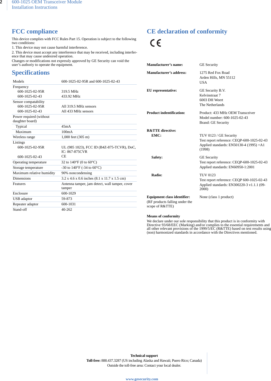
UTC Fire and Security Americas 903-TCVR 319.5 MHz OEM Transceiver w/Crystal TX User Manual TechComm Style Guide

UTC Fire & Security Americas Corporation, Inc. 319.5 MHz OEM Transceiver w/Crystal TX TechComm Style Guide

User Manual

466-2226BMay 2005600-1025 OEM Transceiver ModuleInstallation InstructionsDescriptionThe OEM transceiver modules are compatible with GE Security wireless transmitters. The modules have an onboard receiver, microprocessor, and connection for a daughter board. The micro-processor controls the receiver, providing antenna switching and AGC functions. It also analyzes the received data from the receiver, validates incoming packets, and returns packets to the receiver when polled. A daughter board, which communicates with the module via an 8-pin header, can be added to implement a variety of functions.Each module encapsulates the receiver functions and formats and presents a common interface to the daughter board. Therefore, even though protocols vary among the GE Security radio frequencies used around the world, the interface is the same to the daughter board.Installation guidelinesObserve the following guidelines when installing the OEM trans-ceiver module:• Allow at least 9 inches (22.9 cm) of clearance above the enclosure for the antennas.• Avoid mounting locations that expose the module to mois-ture.• Avoid areas with excessive metal or electrical wiring including furnace and utility rooms. If unavoidable, mount on or near metal with the antenna extending above the metallic surfaces as shown in Figure 1.Figure 1. Mounting on or near metalNote:   For UL installations this module must be mounted in the 600-1029 enclosure. Daughter boards have not been investigated for use by UL.InstallationTo mount the OEM transceiver module onto the back plate of the 600-1029 enclosure, do the following:1. Insert the antennas into the antenna shrouds (Figure 2).2. Gently slide the top of the circuit board under the two top latches.3. Snap the circuit board in at the bottom latch to secure it in place as shown in Figure 2.Figure 2. Installing the circuit board4. Connect DC power to the OEM transceiver module using 2 mm power jacks (center positive) or connect flyleads to the terminal block as labeled on the board.Note:   For model 600-1025-02-43, the cable length must be less than 3 m (9.8 ft.) for CE compliance.LED operationTable 1 shows the LED indications for the OEM transceiver module.TroubleshootingThe following table gives troubleshooting suggestions for the OEM transceiver module.CAUTION You must be free of static electricity before handling circuit boards. Wear a grounding strap or touch a bare metal surface to discharge static electricity.Metal MetalTable 1. OEM transceiver module LED indicationsIndication Green LED Red LEDPowered up On OffCommunication with daughter baord On FlashingValid packet received One flash off Off or flashingTable 2. OEM transceiver module troubleshootingProblem ActionOEM transceiver module’s green and red LEDs are off 1. Check that the transformer is plugged in.2. Check the transformer to module wiring.OEM receiver module’s green LED is on and the red LED is off Check the daughter board mounting.ON                   ON                   1   2   3   4   5   6   7   81   2   3   4   5   6   7   8Antenna shrouds600-1029 enclosureTop latchesBottom latch2 mm power jackTerminal blockOEM transceiver LEDs
600-1025 OEM Transceiver ModuleInstallation Instructions2FCC complianceThis device complies with FCC Rules Part 15. Operation is subject to the following two conditions:1. This device may not cause harmful interference.2. This device must accept any interference that may be received, including interfer-ence that may cause undesired operation. Changes or modifications not expressly approved by GE Security can void the user’s authoriy to operate the equipment. SpecificationsCE declaration of conformityMeans of conformityWe declare under our sole responsibility that this product is in conformity with Directive 93/68/EEC (Marking) and/or complies to the essential requirements and all other relevant provisions of the 1999/5/EC (R&TTE) based on test results using (non) harmonized standards in accordance with the Directives mentioned.Models      600-1025-02-95R and 600-1025-02-43Frequency     600-1025-02-95R     600-1025-02-43319.5 MHz433.92 MHzSensor compatability     600-1025-02-95R     600-1025-02-43All 319.5 MHz sensorsAll 433 MHz sensorsPower required (without daughter board)   Typical 45mA   Maximum 100mAWireless range 1,000 feet (305 m)Listings     600-1025-02-95R          600-1025-02-43UL (985 1023), FCC ID (B4Z-875-TCVR), DoC, IC: 867-875CVRCEOperating temperature 32 to 140°F (0 to 60°C)Storage temperature -30 to 140°F (-34 to 60°C)Maximum relative humidity 90% noncondensingDimensions 3.2 x 4.6 x 0.6 inches (8.1 x 11.7 x 1.5 cm)Features Antenna tamper, jam detect, wall tamper, cover tamperEnclosure 600-1029USB adaptor 59-873Repeater adaptor 600-1031Stand-off 40-262Manufacturer’s name: GE SecurityManufacturer’s address: 1275 Red Fox RoadArden Hills, MN 55112USAEU representative: GE Security B.V.Kelvinstraat 76003 DH WeertThe NetherlandsProduct indentification: Product: 433 MHz OEM Transceiver Model number: 600-1025-02-43Brand: GE SecurityR&TTE directive:     EMC: TUV 0123 / GE SecurityTest report reference: CEQP-600-1025-02-43Applied standards: EN50130-4 (1995) +A1 (1998)     Safety: GE SecurityTest report reference: CEQP-600-1025-02-43Applied standards: EN60950-1:2001     Radio: TUV 0123Test report reference: CEQP 600-1025-02-43Applied standards: EN300220-3 v1.1.1 (09-2000)Equipment class identifier:(RF products falling under the scope of R&TTE)None (class 1 product)Technical supportToll-free: 888.437.3287 (US including Alaska and Hawaii; Puero Rico; Canada)Outside the toll-free area: Contact your local dealer.www.gesecurity.com

Navigation menu