UTC Fire and Security AA3 RCR-50, RCR-PET, RCR-C User Manual 1037946C RCR PET I I P65
UTC Fire & Security B.V. RCR-50, RCR-PET, RCR-C 1037946C RCR PET I I P65
Contents
- 1. Manual 1
- 2. Manual 2
- 3. Manual 3
Manual 3

1
PrecisionLine RCR-PET
PrecisionLine
RCR-PET
Dual Technology Motion Sensor
Installation Instructions
Description
PrecisionLine dual technology motion sensors combine
range-controlled radar (RCR) technology with a passive
infrared (PIR) system to increase false alarm immunity by
allowing them to sense human-sized objects within a speci-
fied range. Both the RCR and PIR systems must be triggered
to set off an alarm.
The sensor is designed to use a 12VDC power supply
provided by a UL Listed control panel.
Features
The sensor provides the following features:
•Pet Immune up to 80 lbs.
•Selectable range up to 35 feet (10.7m) - Internal jumper
allows radar range selection to optimize coverage.
•LED indicator - A multi-color LED provides detector
status.
• Opaque Fresnel lens - Blocks visible light.
Parts
The following parts are included with the sensor:
• RCR-PET sensor
•1 screw to join the case halves
•2 factory-installed jumpers
Selecting a Location for the Sensor
The sensor can be mounted in a corner or on a flat wall. Use
the following guidelines to determine the best location to
install the sensor:
•Mount the sensor so the expected movement of an
intruder is within a 90-degree radius in front of the sensor.
See Figure 2.
•Mount the sensor on a stable surface 7 to 8 feet (2.1 to
2.4m) high.
•DO NOT mount the sensor within 2 feet (0.6m) of metallic
objects.
•DO NOT place objects in front of the sensor that may
prevent a clear line of sight.
•Avoid locations that expose the sensor to possible false
alarm sources such as:
– Moving or vibrating objects (fans, pulleys, conveyor belts)
– Electronic fields (electric motors, high voltage equipment)
– Water spray or corrosive environments
– Heat sources (heaters, radiators) in the field of view
– Windows in the field of view
– Strong air drafts on the sensor (fans, air conditioners)
Figure 1. Sensor (exploded)
Figure 2 - RCR and PIR Coverage Patterns
60° 30° 15°
4°
7’
(2.1m)
90°
35’
(10.7m)
35’
(10.7m)
27’
(8.2m)
27’
(8.2m)
18’
(5.5m)
18’
(5.5m)
9’
(2.7m)
9’
(2.7m)
0’
0’
Top View
Side View
floor line
Radar
PIR
2PrecisionLine RCR-PET
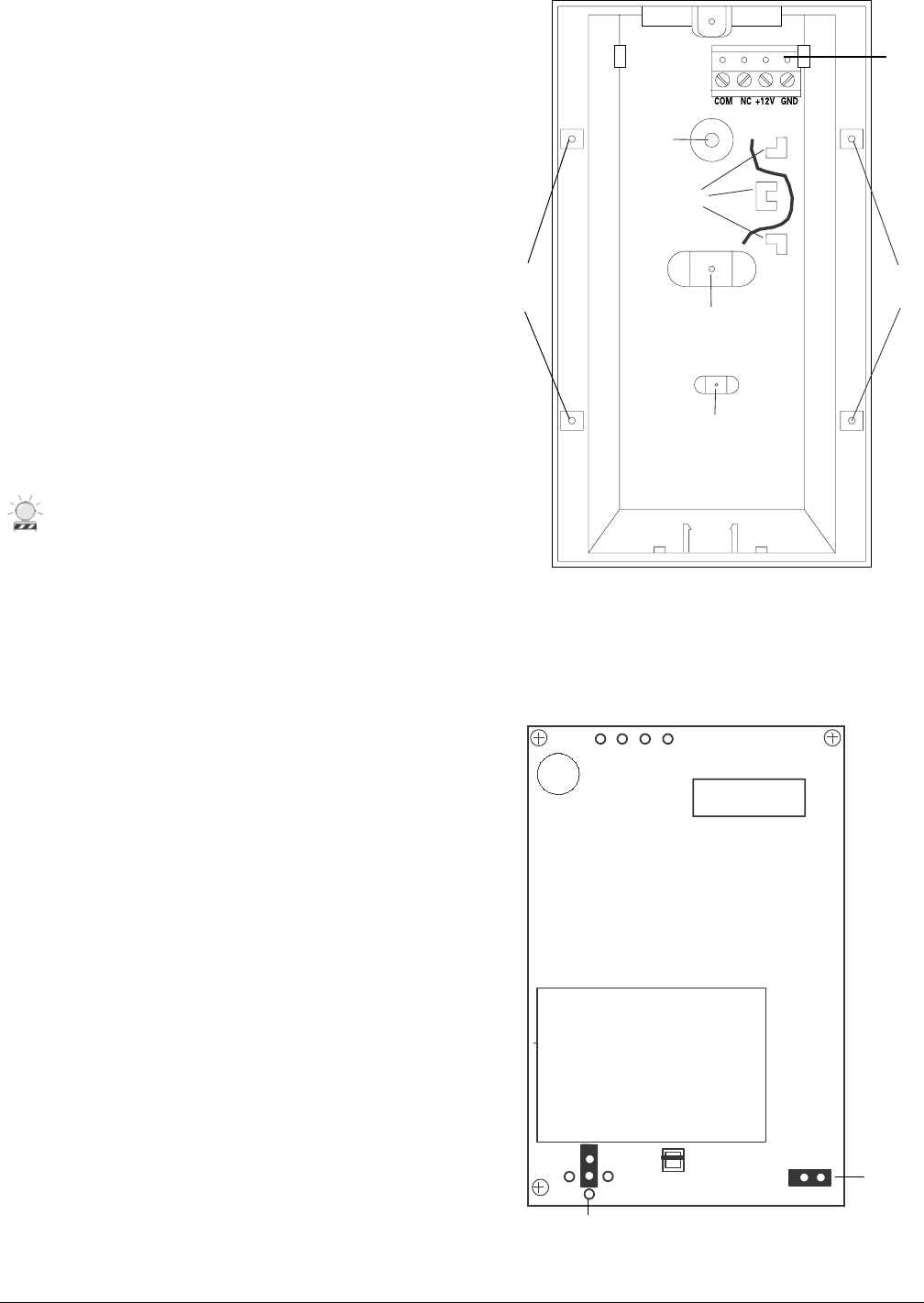
Figure 3. Sensor Base
•When installing multiple sensors:
– DO NOT mount sensors facing each other.
– Mount them at least 20 feet (6.1m) apart.
– Mounting sensors back to back is not recommended, but
if an application requires such mounting, use the 9-foot
(2.7m) range, mount at least 1foot (0.3m) apart, and walk test
the installation to ensure proper operation.
Installing the Sensor
All wiring must conform to the National Electric Code (NEC)
and/or local codes having jurisdiction.
Important: DO NOT use this device for safety interlock
applications.
Use the following steps to install the sensor:
1. Run the security system wiring to the sensor location.
2. Lift off the front cover/electronic module. Remove the
nameplate and loosen the screw if necessary. See
Figure 1.
CAUTION
You must be free of all static electricity before
handling sensor circuit boards. Touch a
grounded, bare metal surface before touching
circuit boards or wear a grounding strap.
3. If necessary, set the jumpers on the circuit board. See
Setting the Jumpers.
4. Remove the appropriate wiring and mounting knock-
outs from the back cover. The sensor can be mounted
on a flat wall or in a corner. See Figure 3.
5. Pull the wires through the knockout holes and use the
two screws provided to attach the base to the wall. Use
screw anchors if necessary.
6. Strip 1/4 inch (6.4 mm) of insulation from each wire.
7. Run each wire through the strain relief and under the
appropriate screw terminals on the base and tighten
the screws. See Figure 3.
8. Line up the tabs on the bottom of the cover/electronic
module with the corresponding tabs on bottom of the
base and snap the cover/electronic module firmly down
onto the base.
9. Tighten the screw and replace the nameplate. See
Figure 1.
10. Apply power. The LED should light green for approxi-
mately 25 seconds and then go out.
11. Walk test the coverage pattern as follows:
– Walk throughout the intended coverage area.
– Verify the sensor alarms. See Understanding the LED.
Figure 4. Main Circuit Board
J3
J2
J2 Range
J3 LED
Disable
Terminal
sockets
Corner-
mount
knockouts
Flat wall-
mount
knockout
Flat wall-
mount
knockout
Wiring
knockout
Strain relief
Corner-
mount
knockouts

3
PrecisionLine RCR-PET
Understanding the LED
The multi-color LED located on the bottom of the sensor
indicates the status of the unit as described in the following
table.
Maintaining the Sensor
When installed and used properly, the sensor provides
years of service with minimal maintenance. You should walk
test the sensor annually to ensure proper operation.
SB01 Swivel Mount Bracket
For ceiling-mount applications that require 90 degree
coverage, an optional ceiling-mount swivel bracket (SB01) is
available. See Figure 5.
Figure 5. SB01 Swivel-Mount Bracket
After 30 minutes the LED will only indicate an alarm condi-
tion. Drop power to reset the walktest timer.
(Pet immunity not verified by UL.)
riahgnoL pu)gnol"2( .sbl08ot
riahmuideM )gnol"5.1( .sbl05otpu
riahtrohS otpu)gnol"1( .sbl03
dednemmocertoN
yellatepesU noitacilppa
koonihCeilloCijnesaBnamreboD
yksuHretteShsilgnEreirreTredroBenaDtaerG
eldooPretnioPleinapSrekcoCdnuohyerG
reveirteRguPgodlluBhcnerFffitsaM
godpeehSeldooPyoTreirreTlluBiniMlluBtiP
drehpehSrenaremieWigroChsleWdranreB.tS
staC
Pet Immunity
When mounted properly, the RCR-PET sensor provides false
alarm immunity to dogs and similar animals. The size and
temperature of the animal, which is affected by the length of
the animal’s coat, affects the immunity to false alarms. Dogs
vary in body temperature by breed, a very warm-blooded dog
with short hair will not be as immune to false alarms as a
similar sized dog with long hair. Therefore, the acceptable
short hair dog is limited to a smaller (lighter) weight dog. See
the examples listed in the following table:
Important: You need to set J2 as close to the intended
coverage range as possible. Overshooting the coverage
area may cause false alarms.
J3 LED -
ON = LED enabled (factory default)
OFF = LED disabled
Setting the Jumpers
The sensor provides jumpers to select the detection range
and LED operation. See Figure 4.
J2 Range - Use the jumper to cover the center pin and the pin
indicating the desired range. No jumper = 27 feet (8.2m) and
under.
35 feet (10.7m) and under 27 feet (8.2m) and under
(Factory default)
18 feet (5.5m)and under 9 feet (2.7m) and under
9’
(2.7m) 9’
(2.7m)
18’
(5.5m) 18’
(5.5m)
35’
(10.7m) 35’
(10.7m)
27’
(8.2m) 27’
(8.2m)
9’
(2.7m)
9’
(2.7m)
18’
(5.5m)
18’
(5.5m)
35’
(10.7m) 35’
(10.7m)
27’
(8.2m) 27’
(8.2m)
LED Status
Red PIR and RCR detection. The sensor is in
alarm and the relay has switched.
Green PIR detection only (no alarm).
Yellow RCR detection only (no alarm).

Specifications
Input voltage 8.5 to 18VDC (UL: 10 to 16VDC)
Typical current 20mA
Maximum current 27mA
Electrical configuration Form A
Relay rating 40VDC, 300mA max.,
6W Load max.
Detection range 35' (10.7m) x 90°
Target velocity 0.5 ft/sec to 5 ft/sec
Alarm duration 5 sec. ± 10%
Mounting height 7' to 8' (2.1m to 2.4m)
Operating temperature 32°F to 122°F (0°C to 50°C)
Relative humidity 5 to 93% non-condensing
Dimensions
Width 2.8" (71mm)
Height 5.1" (130mm)
Depth 2.3" (58mm)
Weight 6 oz (170g)
Color White
Field wiring size 12-24 AWG
Listings C-UL US
FCC Compliance
This device complies with Part 15 of the FCC rules.
Operation is subject to the following two conditions:
(1) This device may not cause harmful interference.
(2) This device must accept any interference received,in-
cluding interference that may cause undesired operation.
FCC ID: CGGAA3
Product Ordering
Model Number Description
RCR-PET PrecisionLine Dual Technology Motion Sensor with Pet Immunity up to 80 lbs., Form A
Accessories
SB01 Swivel-Mount Bracket
1037946 Rev C 04/04
Tech Support
800-648-7424
FaxBack: 800-483-2495
www.ge-security.com
GE Security
12345 SW Leveton Drive
Tualatin, OR 97062
503-692-4052
USA & Canada: 800-547-2556
GE Securi
ty
g