UTC Fire and Security AA3 RCR-50, RCR-PET, RCR-C User Manual 1035261D RCR A C I I P65
UTC Fire & Security B.V. RCR-50, RCR-PET, RCR-C 1035261D RCR A C I I P65
Contents
- 1. Manual 1
- 2. Manual 2
- 3. Manual 3
Manual 1
1
PrecisionLine RCR-A/RCR-C
Description
PrecisionLine dual technology sensors combine range-controlled
radar (RCR) technology with a passive infrared (PIR) system to
increase false alarm immunity by allowing them to sense human-
sized objects within a specified range. Both the RCR and PIR
systems must be triggered to set off an alarm, unless in stealth mode
(radar-only).
The detector is designed to use a 12VDC power supply provided
by a UL Listed alarm control panel.
Features
The detector provides the following features:
•Stealth Mode (radar only) - Internal jumper allows you to
disable the PIR, and use the radar only to detect intruders faster.
This mode can be used for covert installations (mounted behind
walls).
•Selectable range up to 35 feet (10.7m) - Internal jumper
allows radar range selection to optimize coverage.
•LED indicator - A multi-color LED provides detector status.
•Tamper switch (RCR-C only) - Activated when the pins on the
circuit board are removed from the terminal sockets on the base.
Parts
The following parts are included with the detector:
•RCR detector
•1 screw to join the case halves
•3 factory-installed jumpers
Selecting a Location for the Detector
The detector can be mounted in a corner or on a flat wall. Use the
following guidelines to determine the best location to install the
detector:
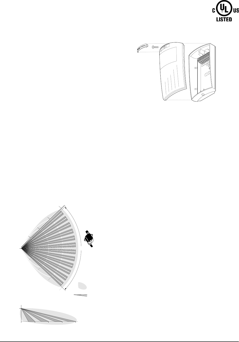
•Mount the detector so the expected movement of an intruder is
across the detection pattern. See Figure 1.
•Mount the detector on a stable surface 7 to 9 feet (2.1 to 2.7m)
high.
•DO NOT mount the detector within 2 feet (0.6m) of any metallic
objects or within 5 feet (1.5m) of any florescent lights.
•DO NOT place any objects in front of the detector that may
prevent a clear line of sight. Not applicable in High Security
Mode (radar only).
•Avoid locations that expose the detector to possible false alarm
sources such as:
– Moving or vibrating objects (fans, pulleys, conveyor belts)
– Electronic fields (electric motors, high voltage equipment)
– Water spray or corrosive environments
– Heat sources in the field of view (heaters, radiators)
– Windows in the field of view
– Strong air drafts on the detector (fans, air conditioners)
•When installing multiple detectors:
– DO NOT mount detectors facing each other.
– Mount them at least 20 feet (6.1m) apart.
– Use shorter range settings to avoid overlapping radar coverage.
– Mounting sensors back to back is not recommended, but if
an application requires such mounting, use the 9-foot (2.7m)
range, mount at least 1foot (0.3m) apart, and walk test the
installation to ensure proper operation.
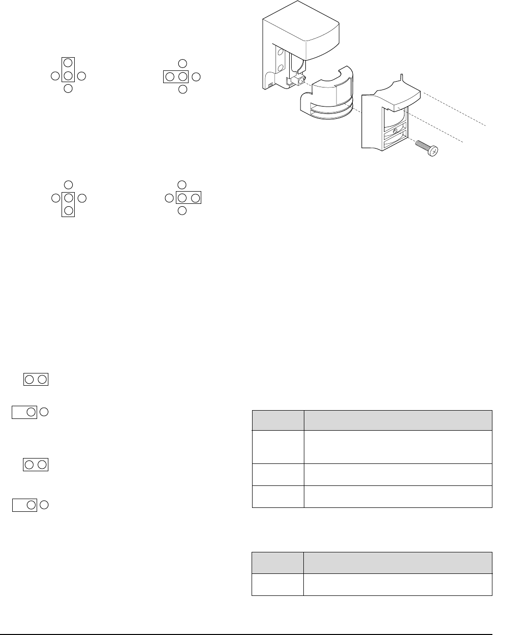
SPR TMPR TMPR NO COM
Figure 2. Detector (exploded)
Figure 1. RCR and PIR Coverage Patterns
90°
Radar Viewing Area
PIR Viewing Area
Top View
Side View
35’
(10.7m)
35’
(10.7m)
27’
(8.2m)
27’
(8.2m)
18’
(5.5m)
18’
(5.5m)
9’
(2.7m)
9’
(2.7m)
0’
0’
35’
(10.7m)
27’
(8.2m)
18’
(5.5m)
9’
(2.7m)
6.9’
(2.1m)
PrecisionLine
Dual Technology Motion Sensor
Models: RCR-A (Form A)
RCR-C (Form C)
Installation Instructions
2PrecisionLine RCR-A/RCR-C
Installing the Detector
All wiring must conform to National Electric Code (NEC) and/or
local codes having jurisdiction.
Important: DO NOT use this device for safety
interlock applications.
Use the following steps to install the detector:
1. Run the security system wiring to the detector location.
2. To remove the front cover/electronic module, press down on
the lever at the bottom of the unit and pull the cover off.
Remove the nameplate and loosen the screw if necessary. To
remove the nameplate, insert a small screwdriver into one of
the nameplate side slots and gently push in on the nameplate.
See Figure 2.
CAUTION
You must be free of all static electricity before
handling sensor circuit boards. Touch a grounded,
bare metal surface before touching circuit boards or
wear a grounding strap
3. If necessary, set the jumpers on the circuit board. See Setting
the Jumpers.
4. Remove the appropriate wiring and mounting knockout holes
from the back cover. The detector can be mounted on a flat
wall or in a corner. See Figure 3.
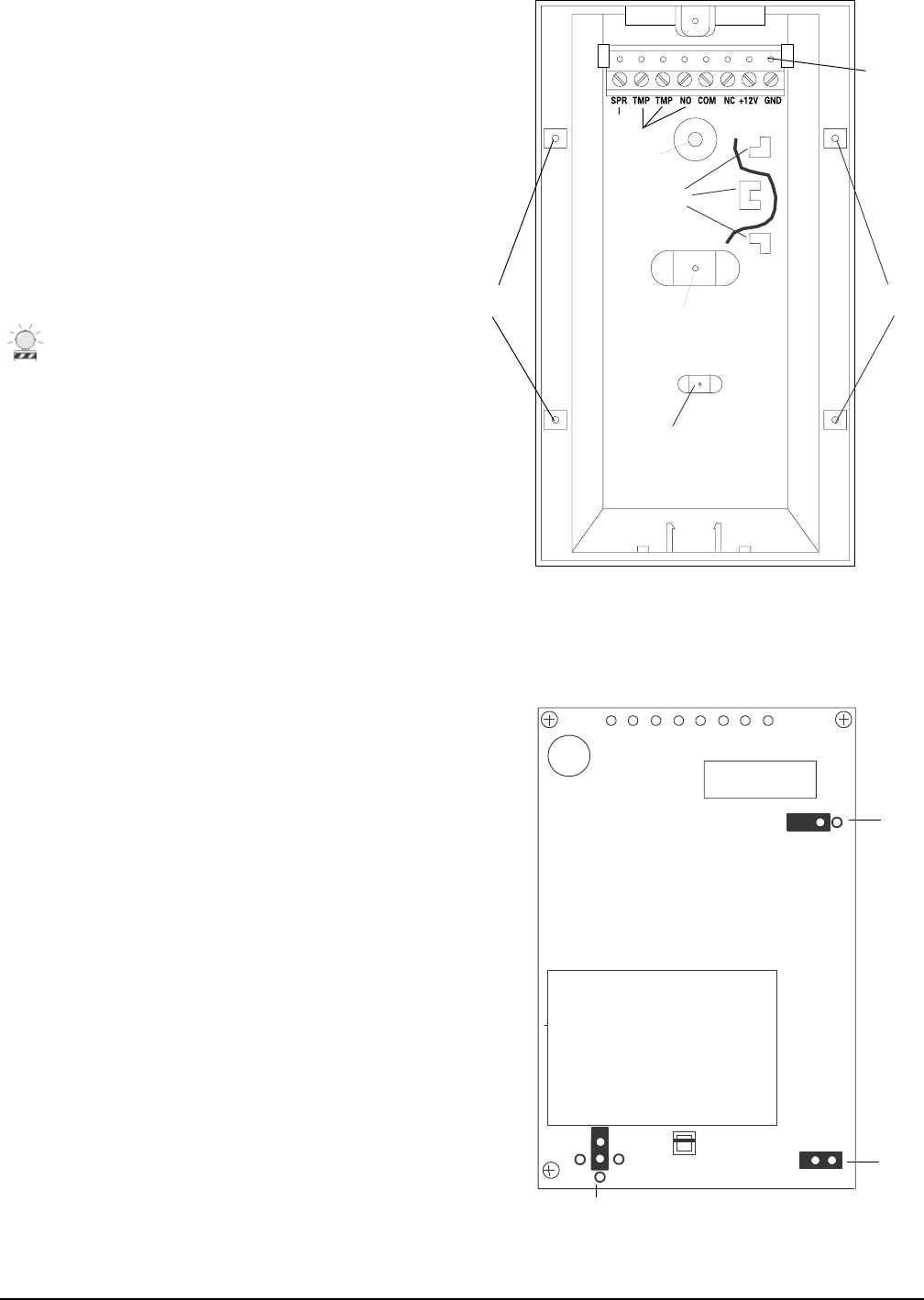
5. Pull the wires through the knockout holes and use screws to
attach the base to the wall. Use screw anchors if necessary.
6. Strip 1/4 inch (6.4mm) of insulation from each wire.
7. Run each wire through the strain relief and into the appropriate
screw terminals on the base. Tighten the screws. See Figure 3.
8. Line up the tabs on the bottom of the cover/electronic module
with the corresponding tabs on the bottom of the base and
snap the cover/electronic module firmly down onto the base.
9. Tighten the screw and replace the nameplate. See Figure 2.
10. Apply power. The green LED should light for approximately
25 seconds and then go out.
11. Walk test the coverage pattern as follows:
– Walk throughout the intended coverage area.
– Verify the detector alarms. See Understanding the LED.
Note
Most units walk test more accurately if the person
testing waits 10 seconds between tripping the unit and
walking again. This allows the detector to stabilize
between trips.
Figure 3. Detector Base
Terminal
sockets
Spare
RCR-C only
Flatwall-mount
knockout
Corner-mount
knockouts
Strain relief
Wiring knockout
Flat-wall mount
knockout
Wire
Corner-mount
knockouts
Figure 4. Main Circuit Board
Radar
only
J4
J3
J2
LED
Disable
Range
3
PrecisionLine RCR-A/RCR-C
Understanding the LED
The multi-color LED located on the bottom of the detector indicates
the status of the unit as described in the following table.
Maintaining the Detector
When installed and used properly, the detector provides years of
service with minimal maintenance. You should walk test the
detector annually to ensure proper operation.
When the cover is removed, power is interrupted to the sensor.
Once the cover has been replaced, the green LED will illuminate for
25 seconds while the sensor warms up. After the green LED goes
off, wait one minute and walk test the sensor.
SB01 Swivel Mount Bracket
For ceiling-mount applications that require 90 degree coverage, an
optional ceiling-mount swivel bracket (SB01) is available from GE
Interlogix. See Figure 5.
Figure 5. SBO1 Swivel-Mount Bracket
Setting the Jumpers
The detector provides jumpers to select the detection range and PIR
and LED operation. See Figure 4.
J2 Range - Use the jumper to cover the center pin and the pin
indicating the desired range. No jumper = 35 feet (10.7m)
and under.
35 feet (10.7m) and under 27 feet (8.2m)and under
(factory default)
18 feet (5.5m)and under 9 feet (2.7m) and under
In Stealth Mode (radar only):
LED Status
Red Radar detection.
Important: You need to set J2 as close to the intended
coverage range as possible. Overshooting the
coverage area may cause false alarms.
J3 LED -
ON = LED enabled (factory default)
OFF = LED disabled
J4 PIR -
ON = Radar only enabled
OFF = PIR and radar enabled (factory default)
9’
(2.7m)
18’
(5.5m)
35’
(10.7m)
27’
(8.2m)
9’
(2.7m)
18’
(5.5m)
35’
(10.7m)
27’
(8.2m)
9’
(2.7m)
18’
(5.5m)
35’
(10.7m)
27’
(8.2m)
9’
(2.7m)
18’
(5.5m)
27’
(8.2m)
35’
(10.7m)
LED Status
Red PIR and radar detection. The detector is in
alarm and the relay has switched.
Green PIR detection only (no alarm).
Yellow Radar detection only (no alarm).

Specifications
Input voltage 8.5 to 18 VDC (UL: 10 to 16VDC)
Typical current 20mA
Maximum current 27mA
Electrical configuration RCR-A: Form A
RCR-C: Form C
Relay rating RCR-A: 40VDC, 300mA max., 6W Load max.
RCR-C: 40VDC, 150mA max., 5W Load max.
Tamper (RCR-C only) 100ma, 40VDC
Detection range 35' (10.7 m) x 90°
Target velocity 0.5 ft/sec to 5 ft/sec
Alarm duration 5 sec
Mounting height 7' to 9' (2.1m to 2.7m)
Operating temperature 32° to 122°F (0° to 50°C)
Relative humidity 5 to 93% non-condensing
Dimensions: Width 2.8" (7.1cm)
Depth 2.3" (5.7cm)
Height 5.1" (13cm)
Weight 6 oz (170g)
Color White
Field wiring size 12-24 AWG
Radar frequency 5.8GHz
Listing C-UL US
FCC Compliance
This device complies with Part 15 of the FCC rules. Operation is subject to the following three conditions:
(1) This device may not cause harmful interference
(2) This device must accept any interference received, including interference that may cause undesired
operation.
(3) Changes or modifications not expressly approved by the party responsible for complicance could void the
user’s authority to operate the equipment.
FCC ID: CGGAA3
1035261 Rev D 04/04
Product Ordering
Model Number Description
RCR-A PrecisionLine dual technology utilizing range-controlled radar, passive infrared technology with form A
relay, stealth mode (radar only), selectable range of 9, 18, 27, and 35 feet.
RCR-C PrecisionLine dual technology utilizing range-controlled radar, passive infrared technology with form C
relay, stealth mode (radar only), tamper contacts, selectable range of 9, 18, 27, and 35 feet.
Accessories
SB01 Swivel-mount bracket
Tech Support
800-648-7424
FaxBack: 800-483-2495
www.ge-security.com
GE Security
12345 SW Leveton Drive
Tualatin, OR 97062
503-692-4052
USA & Canada: 800-547-2556
GE Security
g