UTC Fire and Security ATS1190-1192 Access Control Card Reader User Manual Copy of revision 3 ATS 1190 p65

UTC Fire & Security B.V. Access Control Card Reader Copy of revision 3 ATS 1190 p65

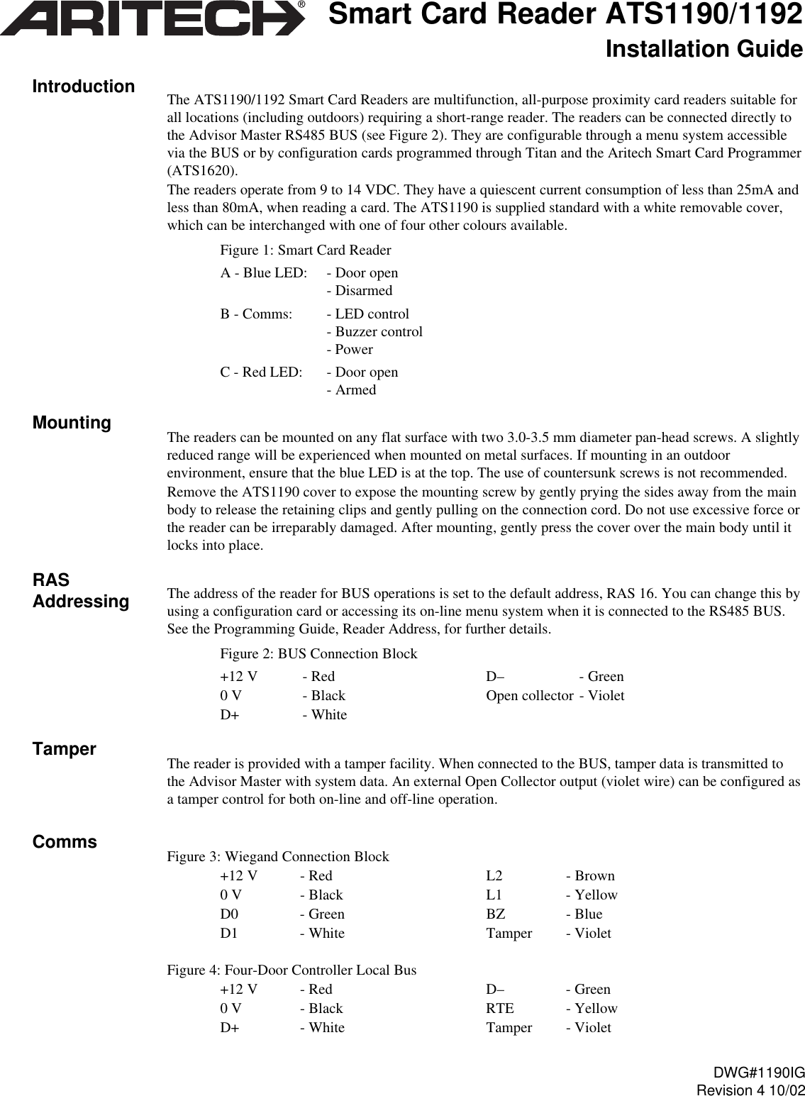
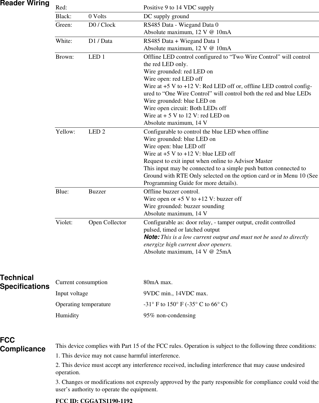
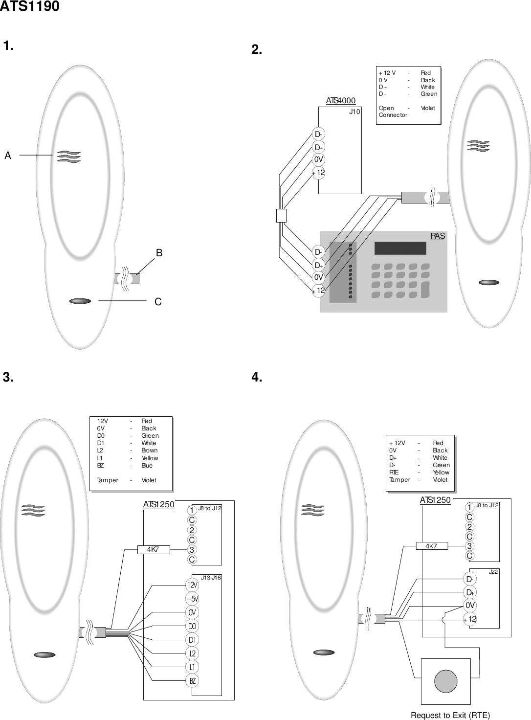
INSTALLATION GUIDE FOR ATS1190 AND 1192

The ATS1190/1192 Smart Card Readers are multifunction, all-purpose proximity card readers suitable forall locations (including outdoors) requiring a short-range reader. The readers can be connected directly tothe Advisor Master RS485 BUS (see Figure 2). They are configurable through a menu system accessiblevia the BUS or by configuration cards programmed through Titan and the Aritech Smart Card Programmer(ATS1620).The readers operate from 9 to 14 VDC. They have a quiescent current consumption of less than 25mA andless than 80mA, when reading a card. The ATS1190 is supplied standard with a white removable cover,which can be interchanged with one of four other colours available.Figure 1: Smart Card ReaderA - Blue LED: - Door open- DisarmedB - Comms: - LED control- Buzzer control- PowerC - Red LED: - Door open- ArmedThe readers can be mounted on any flat surface with two 3.0-3.5 mm diameter pan-head screws. A slightlyreduced range will be experienced when mounted on metal surfaces. If mounting in an outdoorenvironment, ensure that the blue LED is at the top. The use of countersunk screws is not recommended.Remove the ATS1190 cover to expose the mounting screw by gently prying the sides away from the mainbody to release the retaining clips and gently pulling on the connection cord. Do not use excessive force orthe reader can be irreparably damaged. After mounting, gently press the cover over the main body until itlocks into place.The address of the reader for BUS operations is set to the default address, RAS 16. You can change this byusing a configuration card or accessing its on-line menu system when it is connected to the RS485 BUS.See the Programming Guide, Reader Address, for further details.Figure 2: BUS Connection Block+12 V - Red D– - Green0 V - Black Open collector - VioletD+ - WhiteThe reader is provided with a tamper facility. When connected to the BUS, tamper data is transmitted tothe Advisor Master with system data. An external Open Collector output (violet wire) can be configured asa tamper control for both on-line and off-line operation.Figure 3: Wiegand Connection Block+12 V - Red L2 - Brown0 V - Black L1 - YellowD0 - Green BZ - BlueD1 - White Tamper - VioletFigure 4: Four-Door Controller Local Bus+12 V - Red D– - Green0 V - Black RTE - YellowD+ - White Tamper - VioletSmart Card Reader ATS1190/1192Installation GuideIntroductionMountingRASAddressingTamperCommsDWG#1190IGRevision 4 10/02
Red: Positive 9 to 14 VDC supplyBlack: 0 Volts DC supply groundGreen: D0 / Clock RS485 Data - Wiegand Data 0Absolute maximum, 12 V @ 10mAWhite: D1 / Data RS485 Data + Wiegand Data 1Absolute maximum, 12 V @ 10mABrown: LED 1 Offline LED control configured to “Two Wire Control” will controlthe red LED only.Wire grounded: red LED onWire open: red LED offWire at +5 V to +12 V: Red LED off or, offline LED control config-ured to “One Wire Control” will control both the red and blue LEDsWire grounded: blue LED onWire open circuit: Both LEDs offWire at + 5 V to 12 V: red LED onAbsolute maximum, 14 VYellow: LED 2 Configurable to control the blue LED when offlineWire grounded: blue LED onWire open: blue LED offWire at +5 V to +12 V: blue LED offRequest to exit input when online to Advisor MasterThis input may be connected to a simple push button connected toGround with RTE Only selected on the option card or in Menu 10 (SeeProgramming Guide for more details).Blue: Buzzer Offline buzzer control.Wire open or +5 V to +12 V: buzzer offWire grounded: buzzer soundingAbsolute maximum, 14 VViolet: Open Collector Configurable as: door relay, - tamper output, credit controlledpulsed, timed or latched outputNote: This is a low current output and must not be used to directlyenergize high current door openers.Absolute maximum, 14 V @ 25mACurrent consumption 80mA max.Input voltage 9VDC min., 14VDC max.Operating temperature -31° F to 150° F (-35° C to 66° C)Humidity 95% non-condensingThis device complies with Part 15 of the FCC rules. Operation is subject to the following three conditions:1. This device may not cause harmful interference.2. This device must accept any interference received, including interference that may cause undesiredoperation.3. Changes or modifications not expressly approved by the party responsible for compliance could void theuser’s authority to operate the equipment.FCC ID: CGGATS1190-1192Reader WiringTechnicalSpecificationsFCCComplicance
D-D0V12++J10D-D0V12++ATS4000+12V - Red0V - BlackD+ - WhiteD- - GreenOpen - VioletConnec torRA SD-D0V12++1C2C3CJ8 to J12J22+12V - Red0V - BlackD+ - WhiteD- - GreenRTE-YellowTamper - VioletATS1 2 5 01C2C3CJ8 to J12J13-J164K712V - Red0V - BlackD0 - GreenD1 - WhiteL2 - Bro w nL1 - YellowBZ - Bl u eTamper - VioletATS1250ATS11901.1C2C3CJ8 to J12J13-J164K712V - Red0V - BlackD0 - GreenD1 - WhiteL2 - Bro w nL1 - YellowBZ - Bl u eTamper - VioletATS12502.4.3.BACRequest to Exit (RTE)
ATS1192D-D0V12++1C2C3CJ8 to J12J22+12V - Red0V - BlackD+ - WhiteD- - GreenRTE-YellowTamper - VioletATS1250D-D0V12++J10D-D0V12++ATS4 0 0 0+12V - Red0V - BlackD+ - WhiteD - - GreenOpen - VioletConnectorRAS2.4.Request to Exit (RTE)1C2C3CJ8 to J12J13-J164K712V - Red0V - BlackD0 - GreenD1 - WhiteL2 - Bro w nL1 - YellowBZ - Bl u eTamper - VioletATS12501.3.CAB

Navigation menu