UTC Fire and Security ATS1190-1192 Access Control Card Reader User Manual Copy of revision 3 ATS 1190 p65
UTC Fire & Security B.V. Access Control Card Reader Copy of revision 3 ATS 1190 p65
INSTALLATION GUIDE FOR ATS1190 AND 1192

The ATS1190/1192 Smart Card Readers are multifunction, all-purpose proximity card readers suitable for
all locations (including outdoors) requiring a short-range reader. The readers can be connected directly to
the Advisor Master RS485 BUS (see Figure 2). They are configurable through a menu system accessible
via the BUS or by configuration cards programmed through Titan and the Aritech Smart Card Programmer
(ATS1620).
The readers operate from 9 to 14 VDC. They have a quiescent current consumption of less than 25mA and
less than 80mA, when reading a card. The ATS1190 is supplied standard with a white removable cover,
which can be interchanged with one of four other colours available.
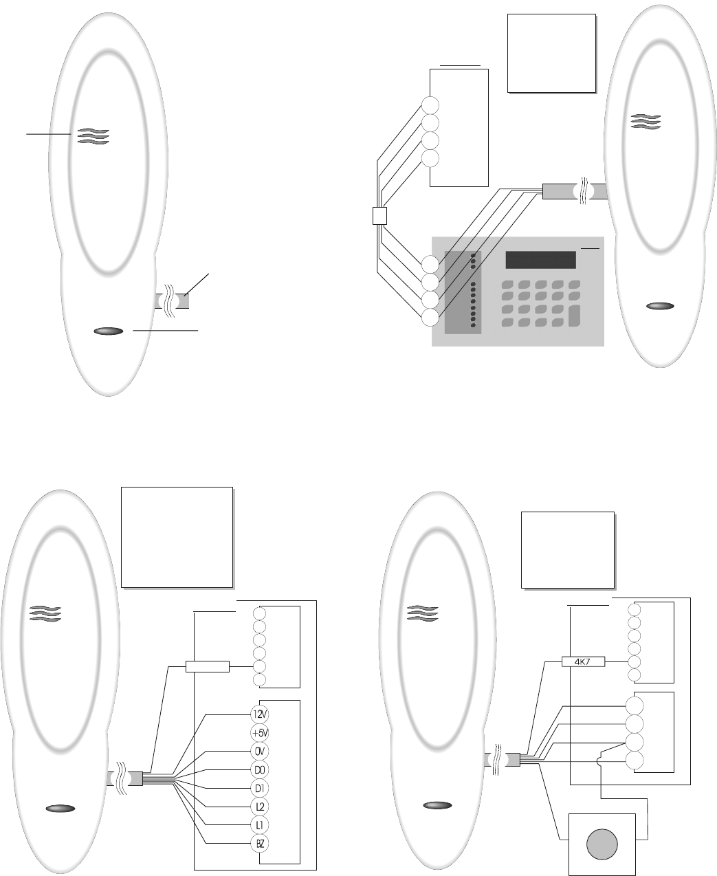
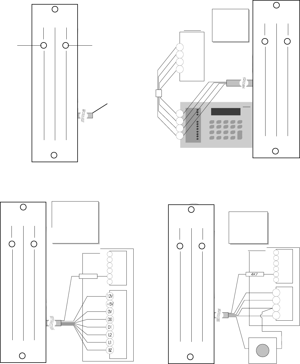
Figure 1: Smart Card Reader
A - Blue LED: - Door open
- Disarmed
B - Comms: - LED control
- Buzzer control
- Power
C - Red LED: - Door open
- Armed
The readers can be mounted on any flat surface with two 3.0-3.5 mm diameter pan-head screws. A slightly
reduced range will be experienced when mounted on metal surfaces. If mounting in an outdoor
environment, ensure that the blue LED is at the top. The use of countersunk screws is not recommended.
Remove the ATS1190 cover to expose the mounting screw by gently prying the sides away from the main
body to release the retaining clips and gently pulling on the connection cord. Do not use excessive force or
the reader can be irreparably damaged. After mounting, gently press the cover over the main body until it
locks into place.
The address of the reader for BUS operations is set to the default address, RAS 16. You can change this by
using a configuration card or accessing its on-line menu system when it is connected to the RS485 BUS.
See the Programming Guide, Reader Address, for further details.
Figure 2: BUS Connection Block
+12 V - Red D– - Green
0 V - Black Open collector - Violet
D+ - White
The reader is provided with a tamper facility. When connected to the BUS, tamper data is transmitted to
the Advisor Master with system data. An external Open Collector output (violet wire) can be configured as
a tamper control for both on-line and off-line operation.
Figure 3: Wiegand Connection Block
+12 V - Red L2 - Brown
0 V - Black L1 - Yellow
D0 - Green BZ - Blue
D1 - White Tamper - Violet
Figure 4: Four-Door Controller Local Bus
+12 V - Red D– - Green
0 V - Black RTE - Yellow
D+ - White Tamper - Violet
Smart Card Reader ATS1190/1192
Installation Guide
Introduction
Mounting
RAS
Addressing
Tamper
Comms
DWG#1190IG
Revision 4 10/02

Red: Positive 9 to 14 VDC supply
Black: 0 Volts DC supply ground
Green: D0 / Clock RS485 Data - Wiegand Data 0
Absolute maximum, 12 V @ 10mA
White: D1 / Data RS485 Data + Wiegand Data 1
Absolute maximum, 12 V @ 10mA
Brown: LED 1 Offline LED control configured to “Two Wire Control” will control
the red LED only.
Wire grounded: red LED on
Wire open: red LED off
Wire at +5 V to +12 V: Red LED off or, offline LED control config-
ured to “One Wire Control” will control both the red and blue LEDs
Wire grounded: blue LED on
Wire open circuit: Both LEDs off
Wire at + 5 V to 12 V: red LED on
Absolute maximum, 14 V
Yellow: LED 2 Configurable to control the blue LED when offline
Wire grounded: blue LED on
Wire open: blue LED off
Wire at +5 V to +12 V: blue LED off
Request to exit input when online to Advisor Master
This input may be connected to a simple push button connected to
Ground with RTE Only selected on the option card or in Menu 10 (See
Programming Guide for more details).
Blue: Buzzer Offline buzzer control.
Wire open or +5 V to +12 V: buzzer off
Wire grounded: buzzer sounding
Absolute maximum, 14 V
Violet: Open Collector Configurable as: door relay, - tamper output, credit controlled
pulsed, timed or latched output
Note: This is a low current output and must not be used to directly
energize high current door openers.
Absolute maximum, 14 V @ 25mA
Current consumption 80mA max.
Input voltage 9VDC min., 14VDC max.
Operating temperature -31° F to 150° F (-35° C to 66° C)
Humidity 95% non-condensing
This device complies with Part 15 of the FCC rules. Operation is subject to the following three conditions:
1. This device may not cause harmful interference.
2. This device must accept any interference received, including interference that may cause undesired
operation.
3. Changes or modifications not expressly approved by the party responsible for compliance could void the
user’s authority to operate the equipment.
FCC ID: CGGATS1190-1192
Reader Wiring
Technical
Specifications
FCC
Complicance
D-
D
0V
12
+
+
J10
D-
D
0V
12
+
+
ATS4000
+12V - Red
0V - Black
D+ - White
D- - Green
Open - Violet
Connec tor
RA S
D-
D
0V
12
+
+
1
C
2
C
3
C
J8 to J12
J22
+12V - Red
0V - Black
D+ - White
D- - Green
RTE-Yellow
Tamper - Violet
ATS1 2 5 0
1
C
2
C
3
C
J8 to J12
J13-J16
4K7
12V - Red
0V - Black
D0 - Green
D1 - White
L2 - Bro w n
L1 - Yellow
BZ - Bl u e
Tamper - Violet
ATS1250
ATS1190
1.
1
C
2
C
3
C
J8 to J12
J13-J16
4K7
12V - Red
0V - Black
D0 - Green
D1 - White
L2 - Bro w n
L1 - Yellow
BZ - Bl u e
Tamper - Violet
ATS1250
2.
4.3.
B
A
C
Request to Exit (RTE)
ATS1192
D-
D
0V
12
+
+
1
C
2
C
3
C
J8 to J12
J22
+12V - Red
0V - Black
D+ - White
D- - Green
RTE-Yellow
Tamper - Violet
ATS1250
D-
D
0V
12
+
+
J10
D-
D
0V
12
+
+
ATS4 0 0 0
+12V - Red
0V - Black
D+ - White
D - - Green
Open - Violet
Connector
RAS
2.
4.
Request to Exit (RTE)
1
C
2
C
3
C
J8 to J12
J13-J16
4K7
12V - Red
0V - Black
D0 - Green
D1 - White
L2 - Bro w n
L1 - Yellow
BZ - Bl u e
Tamper - Violet
ATS1250
1.
3.
CA
B