UTC Fire and Security NX1700E Remote Control Security Device User Manual NX 1700E CARD READER
UTC Fire & Security B.V. Remote Control Security Device NX 1700E CARD READER
UserManual.wiki
>
UTC Fire and Security
>
NX1700E User Manual
INSTALLATION GUIDE FOR NX1700E
Navigation menu
Upload a User Manual
Namespaces
Wiki Guide
HTML
PDF
Info
Views
User Manual
Discussion / Help
Navigation
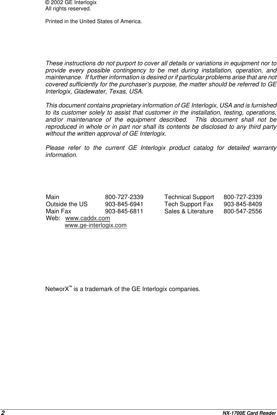
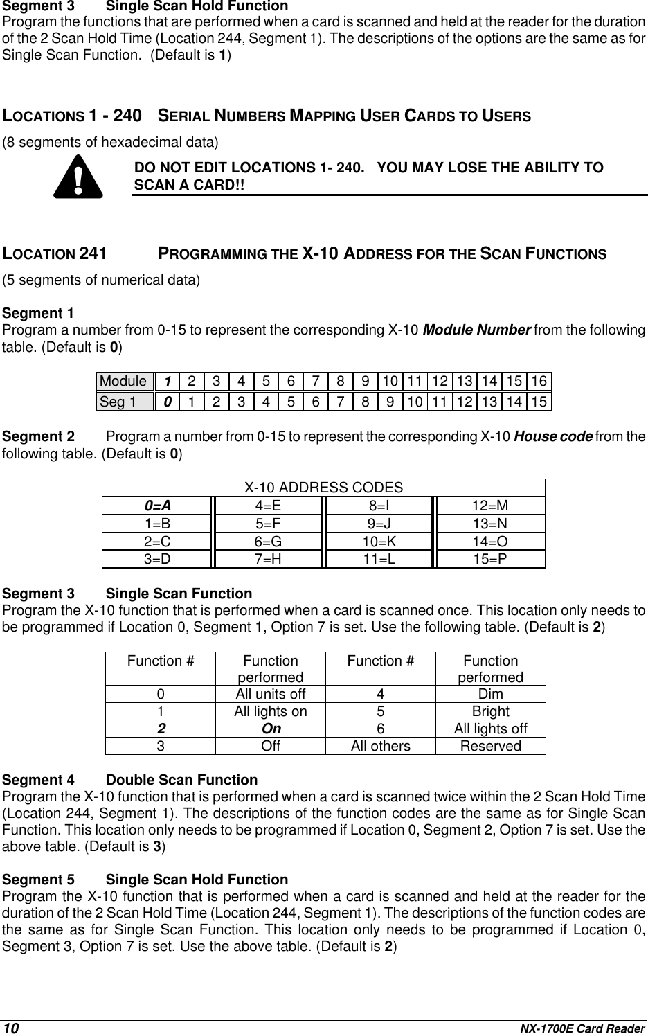
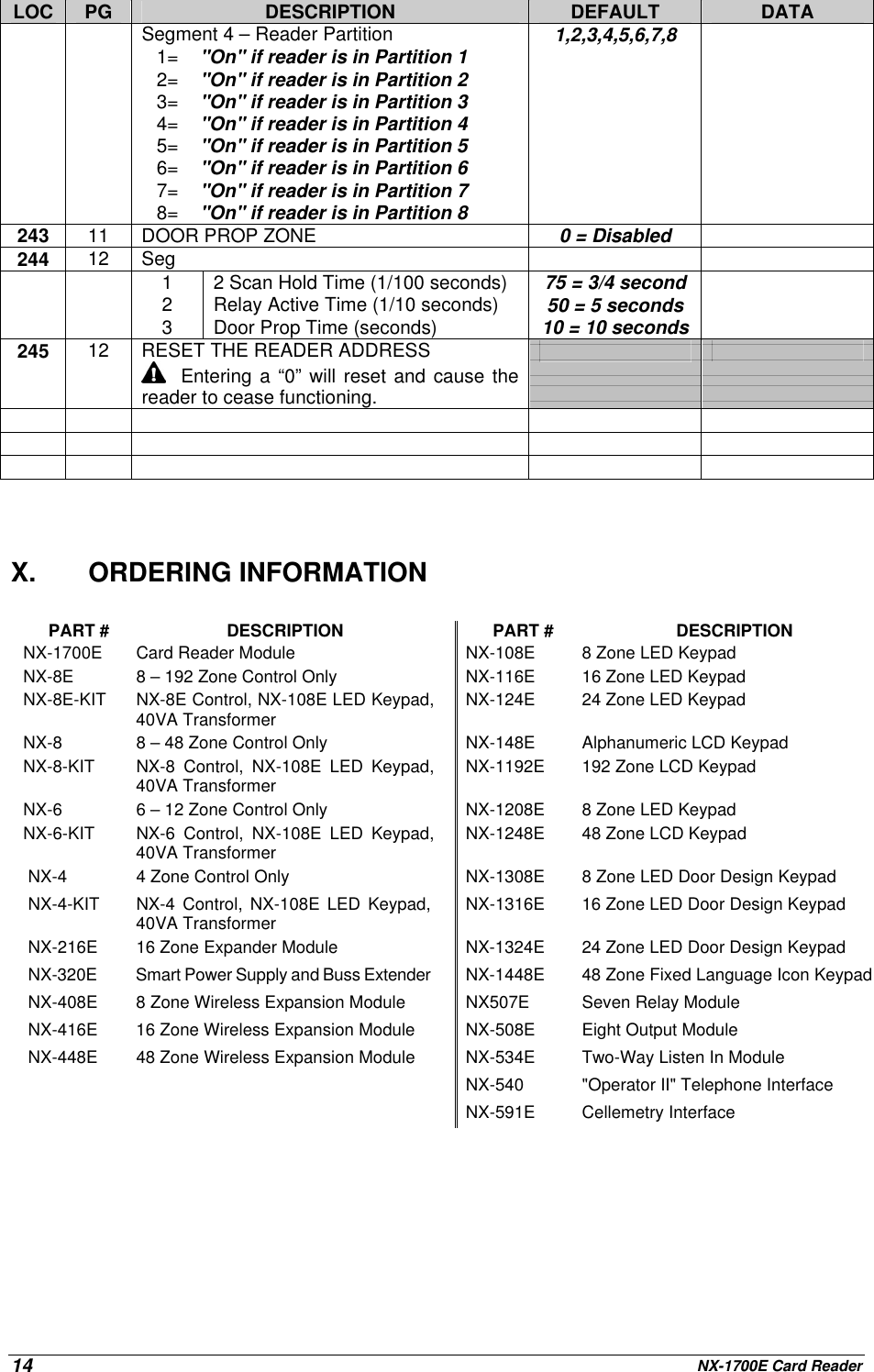
![NX-1700E Card Reader6Scan:To“present” orpass a card orFOB withinsensing rangeof the cardreader module.V. ADDRESSINGOnce the reader is wired into the system, the module needs to be addressed. Unlike mostNetworX expanders, the address of any particular reader is determined by itself afterinstallation is complete. Follow the procedures outlined under the section“PROGRAMMING”. When prompted to enter the module device number, a card must bescanned at the reader to initiate addressing (one short beep). When completed (1-2seconds), the reader will beep back its address (long beeps):Table V-1Beeps Address Beeps Address1 113 9 1212 114 10 1223 115 11 1234 116 12 1245 117 13 1256 118 14 1267 119 15 1278 120VI. PROGRAMMINGA. USING THE LED KEYPADACTION RESULTENTERING THE PROGRAM MODE Enters the Program Mode.Stay,Chime,Exit,Bypass &Cancel LEDS will flash.[Go To Program Code]Factory Default is If the "Go To Program Code" is valid, the "Service"LED will flash and the 5 function LEDs will illuminatesteady. You are now in the Program Mode and readyto select the module address.ENTERING THE MODULE ADDRESSScan a card. The card reader will address itself. #(example only)Enters the module address. Refer to Table V-1 onpage 6 for the address assigned by the card readermodule itself.The Armed LED will illuminate while it is waiting for aprogramming location to be entered.](https://usermanual.wiki/UTC-Fire-and-Security/NX1700E/User-Guide-279776-Page-6.png)
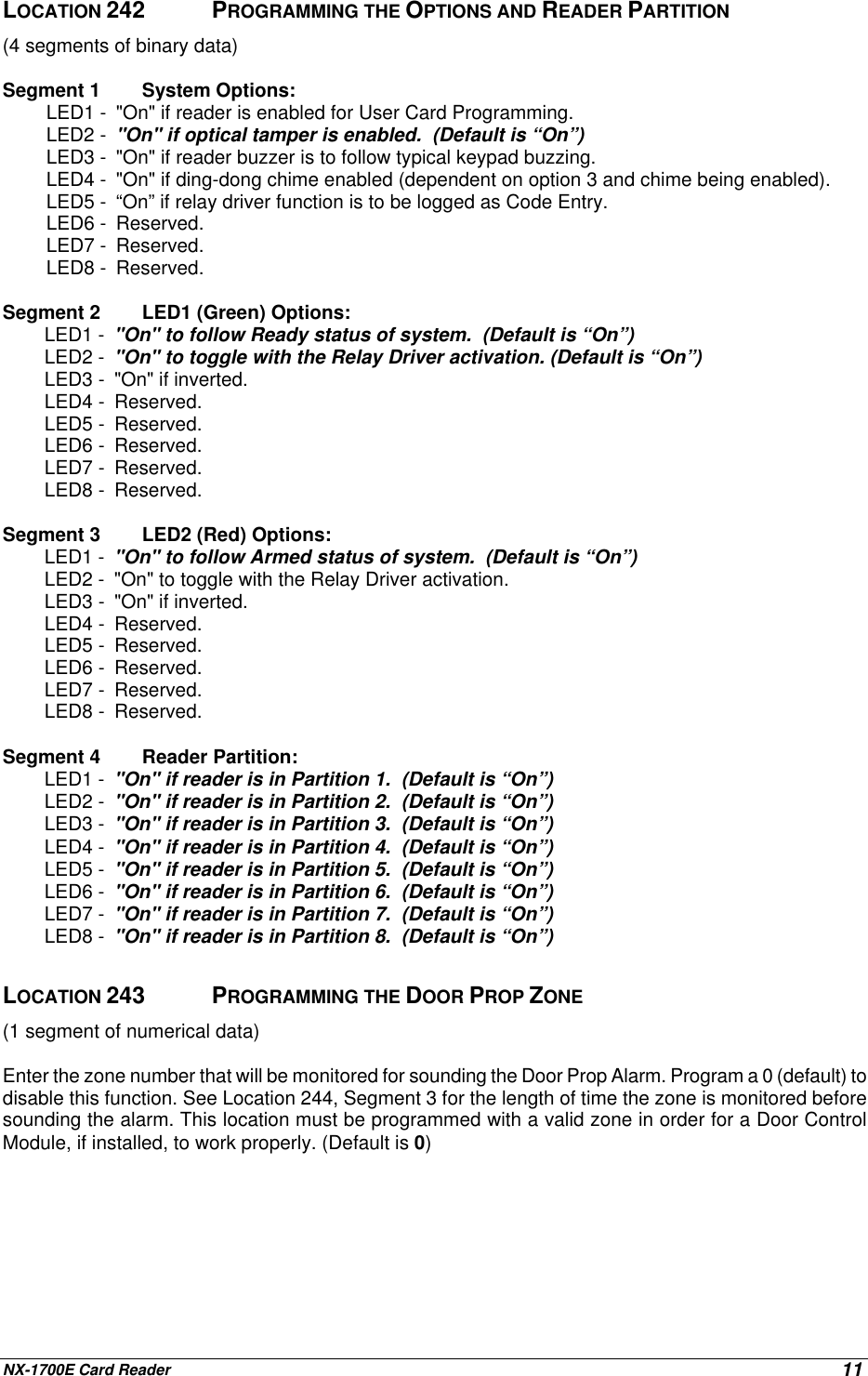
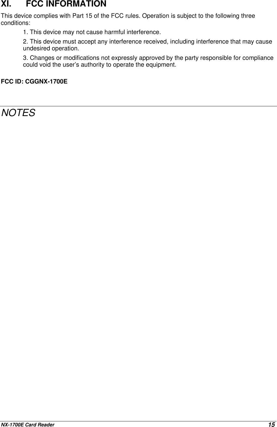
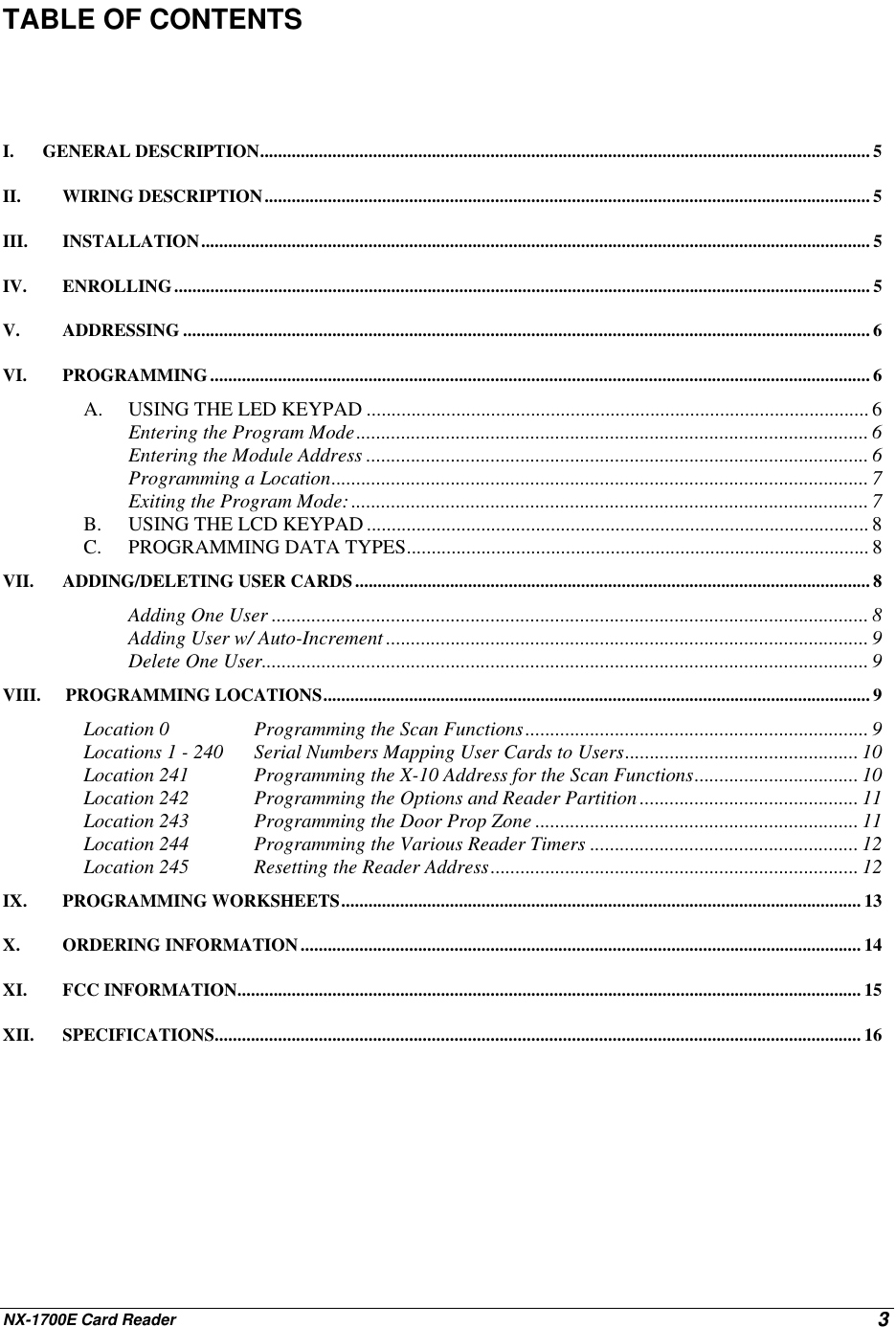
![NX-1700E Card Reader 7ACTION RESULTPROGRAMMING A LOCATIONIf an attempt is made to program an invalid entry for a particular segment, thekeypad sounder will emit a triple error beep (beep, beep, beep), and remain inthat segment awaiting a valid entry.To Enter a Location:[location] # The Armed LED will flash. If the location is valid, the"Armed" LED will extinguish, the "Ready" LED willilluminate, and the zone LED’s will show the data forthe first segment of this location.To Change Location Data:[changed data] The "Ready" LED will flash to indicate a data changein process and will continue until the data is saved. The new data is saved.The keypad will increment and display the nextsegment’s data.NOTE: Repeat these steps until the last segment is reached.To Exit a Location:#Exits from this location. The “Ready” LED willextinguish. The "Armed" LED will illuminate waiting fora new programming location to be entered.To Review The Data:[location] # The Armed LED will flash. If the location number isvalid, the "Armed" LED will extinguish, the "Ready"LED will illuminate, and the zone LEDs will show thebinary data for the first segment of this location. (Do not enter data.)The next segment is displayed. Each time rispressed, the data of the next segment will be displayedfor review.Shortcuts: Previous location.Same location.Next sequential location.EXITING THE PROGRAM MODE:EXIT EXIT Exits this programming level.](https://usermanual.wiki/UTC-Fire-and-Security/NX1700E/User-Guide-279776-Page-7.png)
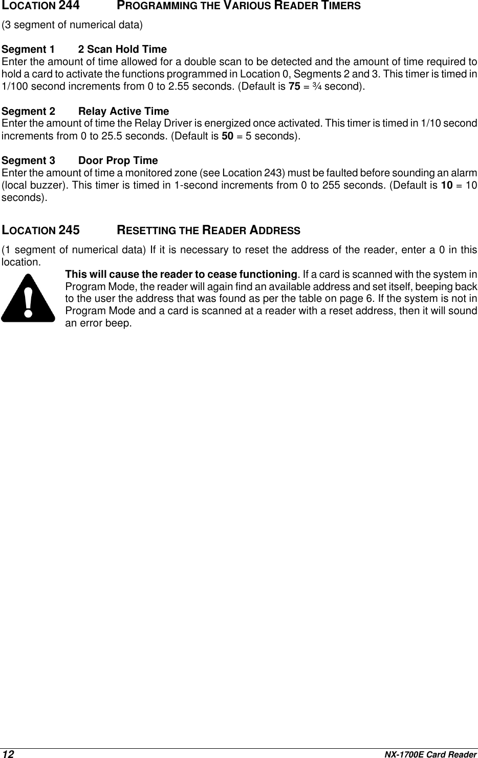
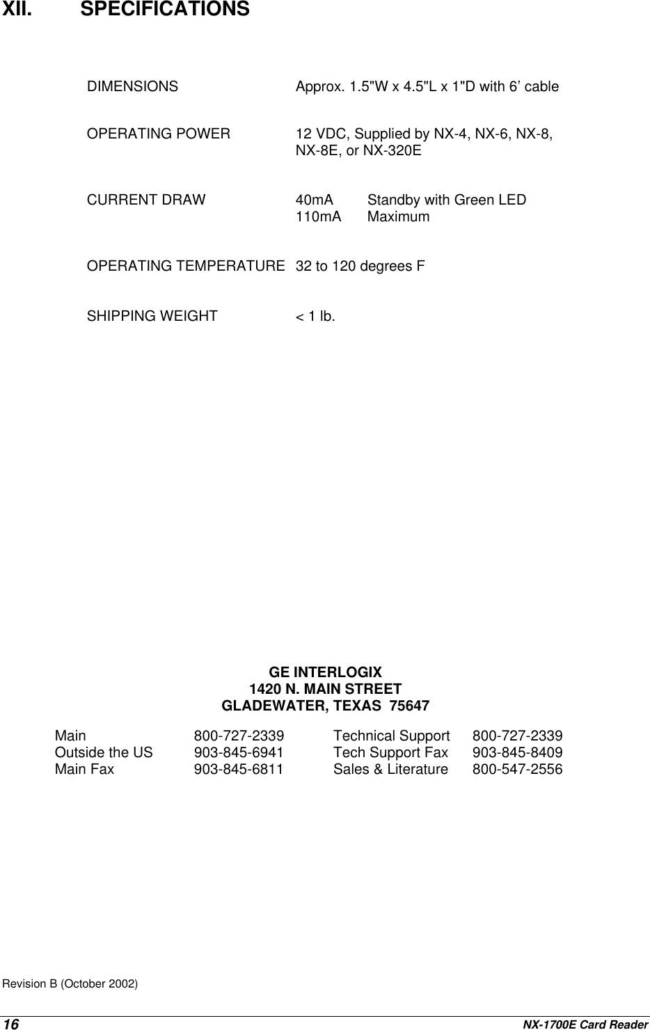
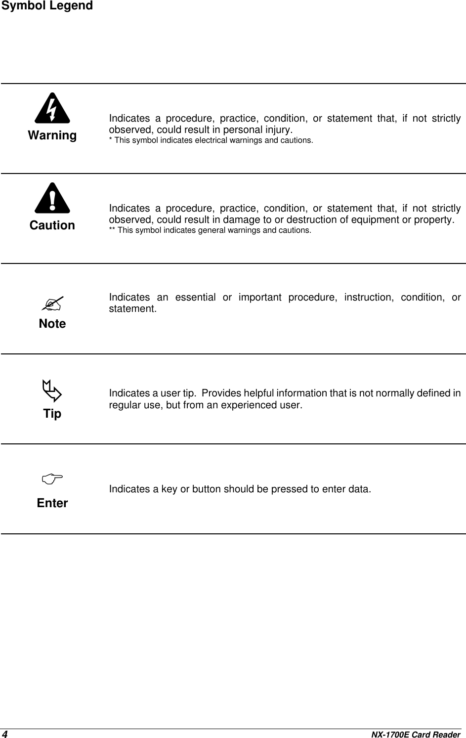
![NX-1700E Card Reader8B. USING THE LCD KEYPADAll steps required for programming are the same as the aforementioned LED keypad. The LCD keypaddisplay will prompt you for the data required. While in the programming mode, and not in a location, thenumber in parenthesis is the location you were previously changing. For example, if the display reads"Enter location, then # (5)", it is reminding you that location 5 was the last location you programmed. Infeature selection data, the numbers of the enabled features will be displayed. The features not enabledwill display a hyphen (-).C. PROGRAMMING DATA TYPESa) Numerical DataNumerical data can take on values from 0-255 or 0-15 depending on the segmentsize.b) Feature SelectionFeature selection data is used to turn features on or off.VII. ADDING/DELETING USER CARDSAdding and deleting users is done through a combination of entering information at the keypad andscanning cards. Before a card can be entered, one reader on the system must be programmed with UserCard Programming enabled (Location 242, Segment 1, Option 1, page 11). It is recommended that onlyone reader on the system be enabled to add/delete user cards and that this reader be located near akeypad. This reader will transfer information to all other readers in the system once programming isfinished. Once a reader is enabled to add/delete users, it must be placed into one of the three followingmodes: 1)AddOneUser;2) Add Multiple Users (or Add User w/ Auto-Increment), and 3) Delete OneUser. Adding and/or deleting users on a card reader is similar to modifying user codes at a keypad.MUST BE A MASTER USER IN ORDER TO ADD OR DELETE USERS.ACTION RESULT Accesses Code Programming[master code]Factory Default is If the code is valid, the Ready LED will flash.User Number 2 is used to program user cards, so…if the control is anNX-4, NX-6, or NX-8if the control isan NX-8EUnit is now ready for you to choose one of the UserCard Programming modes (as if user code 2):1) Add One User2) Add Multiple Users (or Add User w/ Auto-Increment)3) Delete One UserIMPORTANT NOTEAdding or deleting user cards from a reader causes the code for User Number 2 to become invalid.Therefore, it will need to be reentered after all user cards are programmed into the readers.ADDING ONE USERTo add a single user, enter [STAY] followed by the 3-digit “user number” if control is programmed for 4-digit user codes or followed by [0]-[0] and the 3-digit “user number” if control is programmed for 6-digituser codes. A total of 4 or 6 digits must be entered depending on the programming of the control panel;the first being the [STAY] key, the last three being the “user number”. If a valid user number is entered,](https://usermanual.wiki/UTC-Fire-and-Security/NX1700E/User-Guide-279776-Page-8.png)
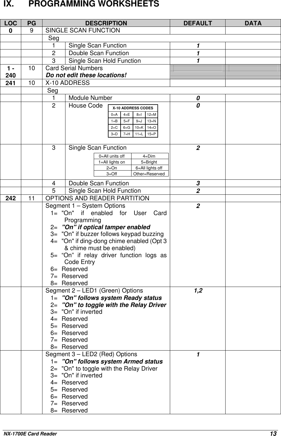
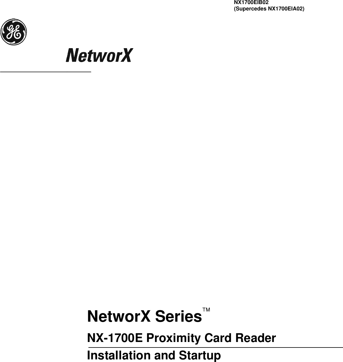
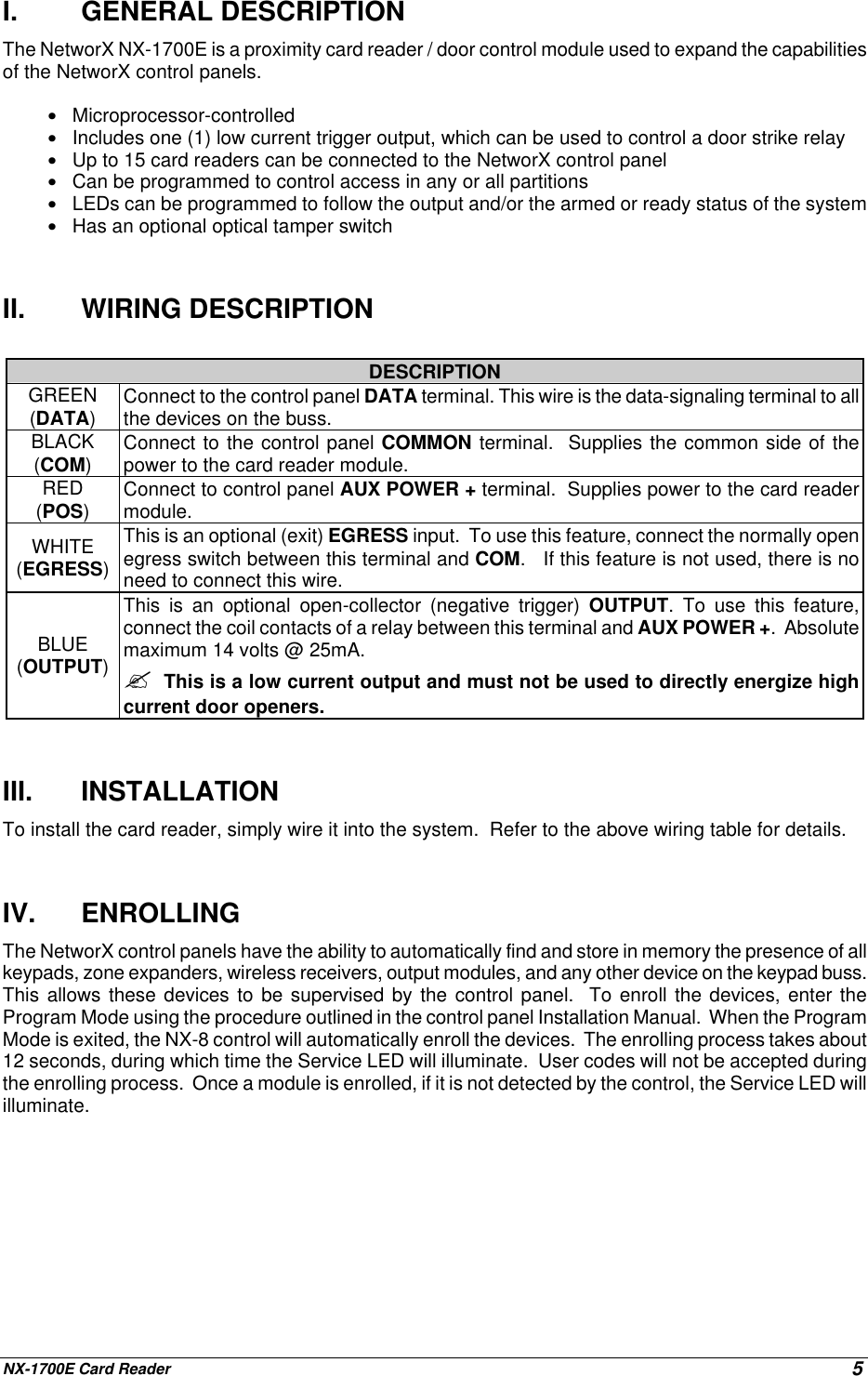
![NX-1700E Card Reader 9LED1 on any enabled readers will begin to flash. Scan the card designated for the entered user. If theuser card is not already in the system, it will be added and mapped to the entered user number andLED1 will stop flashing. If the card is already in the system, the reader will triple beep and LED1 willcontinue flashing. After about 40 seconds, all the readers in the system will be updated with the new usercard information.ADDING USER W/AUTO-INCREMENTTo add multiple users, enter [CANCEL] followed by the 3-digit “user number” of the first user to beentered if control is programmed for 4-digit user codes or followed by [0]-[0] and the 3-digit “usernumber” of the first user to be entered if control is programmed for 6-digit user codes. A total of 4 or 6digits must be entered depending on the programming of the control panel; the first being the [CANCEL]key, the last three being the “user number” of the first user to be entered. If a valid user number isentered, LED1 on any enabled readers will begin to flash. Scan the card designated for the entered user.If the user card is not already in the system, it will be added and mapped to the entered user number andLED1 will continue flashing indicating that the next user card can be scanned for the next user number. Ifthe card is already in the system, the reader will triple beep and LED1 will continue flashing; the usernumber is not incremented in this case. After about 40 seconds of no cards being scanned, all thereaders in the system will be updated with the new user card information.DELETE ONE USERTo delete a single user, enter [EXIT] followed by the 3-digit “user number” if controlis programmed for 4-digit user codes or followed by [0]-[0] and the 3-digit “usernumber” if control is programmed for 6-digit user codes. A total of 4 or 6 digits mustbe entered depending on the programming of the control panel; the first being the[EXIT] key, the last three being the “user number”. If a valid user number is entered,LED1 on any enabled readers will begin to flash. Scan any card. The user cardinformation for the entered user number will be cleared and LED1 will stop flashing.After about 40 seconds, all the readers in the system will be updated with the newuser card information.VIII. PROGRAMMING LOCATIONSLOCATION 0PROGRAMMING THE SCAN FUNCTIONS(3 segments of binary data) Location 0 is used to select the particular function(s) that are activated whena card is scanned. More than one function may be selected. If more than one function is selected, theywill execute in order from function 1 to function 8.Segment 1 Single Scan FunctionProgram the functions that are performed when a card is scanned once.LED 1 - "On" to send Code Entry function to the control panel. (Default is “On”)LED 2 - "On" to activate the Armed Away mode.LED 3 - "On" to activate the Armed Stay mode.LED 4 - "On" to send the Disarm function to the control panel.LED 5 - "On" to send Auxiliary Function #1 to the control panel.LED 6 - "On" to send Auxiliary Function #2 to the control panel.LED 7 - "On" to broadcast an X-10 function (see Location 241 for programming).LED 8 - "On" to activate the relay driver output.Segment 2 Double Scan FunctionProgram the functions that are performed when a card is scanned twice within the 2 Scan Hold Time(Location 244, Segment 1). The descriptions of the options are the same as for Single Scan Function.(Default is 1)If anindividualkeeps thecard,itcanstill bedeleted.](https://usermanual.wiki/UTC-Fire-and-Security/NX1700E/User-Guide-279776-Page-9.png)