UTC Fire and Security NX1700E Remote Control Security Device User Manual NX 1700E CARD READER
UTC Fire & Security B.V. Remote Control Security Device NX 1700E CARD READER
INSTALLATION GUIDE FOR NX1700E

NX1700EIB02
(Supercedes NX1700EIA02)
NetworX Series
NX-1700E Proximity Card Reader
Installation and Startup

NX-1700E Card Reader
2
© 2002 GE Interlogix
All rights reserved.
Printed in the United States of America.
These instructions do not purport to cover all details or variations in equipment nor to
provide every possible contingency to be met during installation, operation, and
maintenance. If further information is desired or if particular problems arise that are not
covered sufficiently for the purchaser’s purpose, the matter should be referred to GE
Interlogix, Gladewater, Texas, USA.
This document contains proprietary information of GE Interlogix, USA and is furnished
to its customer solely to assist that customer in the installation, testing, operations,
and/or maintenance of the equipment described. This document shall not be
reproduced in whole or in part nor shall its contents be disclosed to any third party
without the written approval of GE Interlogix.
Please refer to the current GE Interlogix product catalog for detailed warranty
information.
Main 800-727-2339 Technical Support 800-727-2339
Outside the US 903-845-6941 Tech Support Fax 903-845-8409
Main Fax 903-845-6811 Sales & Literature 800-547-2556
Web: www.caddx.com
www.ge-interlogix.com
NetworXis a trademark of the GE Interlogix companies.

NX-1700E Card Reader 3
TABLE OF CONTENTS
I. GENERAL DESCRIPTION....................................................................................................................................... 5
II. WIRING DESCRIPTION...................................................................................................................................... 5
III. INSTALLATION.................................................................................................................................................... 5
IV. ENROLLING.......................................................................................................................................................... 5
V. ADDRESSING ........................................................................................................................................................ 6
VI. PROGRAMMING .................................................................................................................................................. 6
A. USING THE LED KEYPAD ..................................................................................................... 6
Entering the Program Mode....................................................................................................... 6
Entering the Module Address .....................................................................................................6
Programming a Location............................................................................................................7
Exiting the Program Mode:........................................................................................................ 7
B. USING THE LCD KEYPAD ..................................................................................................... 8
C. PROGRAMMING DATA TYPES............................................................................................. 8
VII. ADDING/DELETING USER CARDS.................................................................................................................. 8
Adding One User ........................................................................................................................ 8
Adding User w/ Auto-Increment ................................................................................................. 9
Delete One User.......................................................................................................................... 9
VIII. PROGRAMMING LOCATIONS......................................................................................................................... 9
Location 0 Programming the Scan Functions..................................................................... 9
Locations 1 - 240 Serial Numbers Mapping User Cards to Users............................................... 10
Location 241 Programming the X-10 Address for the Scan Functions................................. 10
Location 242 Programming the Options and Reader Partition ............................................ 11
Location 243 Programming the Door Prop Zone ................................................................. 11
Location 244 Programming the Various Reader Timers ...................................................... 12
Location 245 Resetting the Reader Address.......................................................................... 12
IX. PROGRAMMING WORKSHEETS................................................................................................................... 13
X. ORDERING INFORMATION............................................................................................................................ 14
XI. FCC INFORMATION.......................................................................................................................................... 15
XII. SPECIFICATIONS............................................................................................................................................... 16

NX-1700E Card Reader
4
Symbol Legend
Warning
Indicates a procedure, practice, condition, or statement that, if not strictly
observed, could result in personal injury.
* This symbol indicates electrical warnings and cautions.
Caution
Indicates a procedure, practice, condition, or statement that, if not strictly
observed, could result in damage to or destruction of equipment or property.
** This symbol indicates general warnings and cautions.
Note
Indicates an essential or important procedure, instruction, condition, or
statement.
Tip
Indicates a user tip. Provides helpful information that is not normally defined in
regular use, but from an experienced user.
Enter
Indicates a key or button should be pressed to enter data.

NX-1700E Card Reader 5
I. GENERAL DESCRIPTION
The NetworX NX-1700E is a proximity card reader / door control module used to expand the capabilities
of the NetworX control panels.
$ Microprocessor-controlled
$ Includes one (1) low current trigger output, which can be used to control a door strike relay
$ Up to 15 card readers can be connected to the NetworX control panel
$ Can be programmed to control access in any or all partitions
$ LEDs can be programmed to follow the output and/or the armed or ready status of the system
$ Has an optional optical tamper switch
II. WIRING DESCRIPTION
DESCRIPTION
GREEN
(DATA)Connect to the control panel DATA terminal. This wire is the data-
signaling terminal to all
the devices on the buss.
BLACK
(COM)Connect to the control panel COMMON
terminal. Supplies the common side of the
power to the card reader module.
RED
(POS)Connect to control panel AUX POWER + terminal. Supplie
s power to the card reader
module.
WHITE
(EGRESS)
This is an optional (exit) EGRESS
input. To use this feature, connect the normally open
egress switch between this terminal and COM
. If this feature is not used, there is no
need to connect this wire.
BLUE
(OUTPUT)
This is an optional open-collector (negative trigger) OUTPUT
. To use this feature,
connect the coil contacts of a relay between this terminal and AUX POWER +
. Absolute
maximum 14 volts @ 25mA.
This is a low current output and must not be
used to directly energize high
current door openers.
III. INSTALLATION
To install the card reader, simply wire it into the system. Refer to the above wiring table for details.
IV. ENROLLING
The NetworX control panels have the ability to automatically find and store in memory the presence of all
keypads, zone expanders, wireless receivers, output modules, and any other device on the keypad buss.
This allows these devices to be supervised by the control panel. To enroll the devices, enter the
Program Mode using the procedure outlined in the control panel Installation Manual. When the Program
Mode is exited, the NX-8 control will automatically enroll the devices. The enrolling process takes about
12 seconds, during which time the Service LED will illuminate. User codes will not be accepted during
the enrolling process. Once a module is enrolled, if it is not detected by the control, the Service LED will
illuminate.
NX-1700E Card Reader
6
Scan:To
“present” or
pass a card or
FOB within
sensing range
of the card
reader module.
V. ADDRESSING
Once the reader is wired into the system, the module needs to be addressed. Unlike most
NetworX expanders, the address of any particular reader is determined by itself after
installation is complete. Follow the procedures outlined under the section
“PROGRAMMING”. When prompted to enter the module device number, a card must be
scanned at the reader to initiate addressing (one short beep). When completed (1-2
seconds), the reader will beep back its address (long beeps):
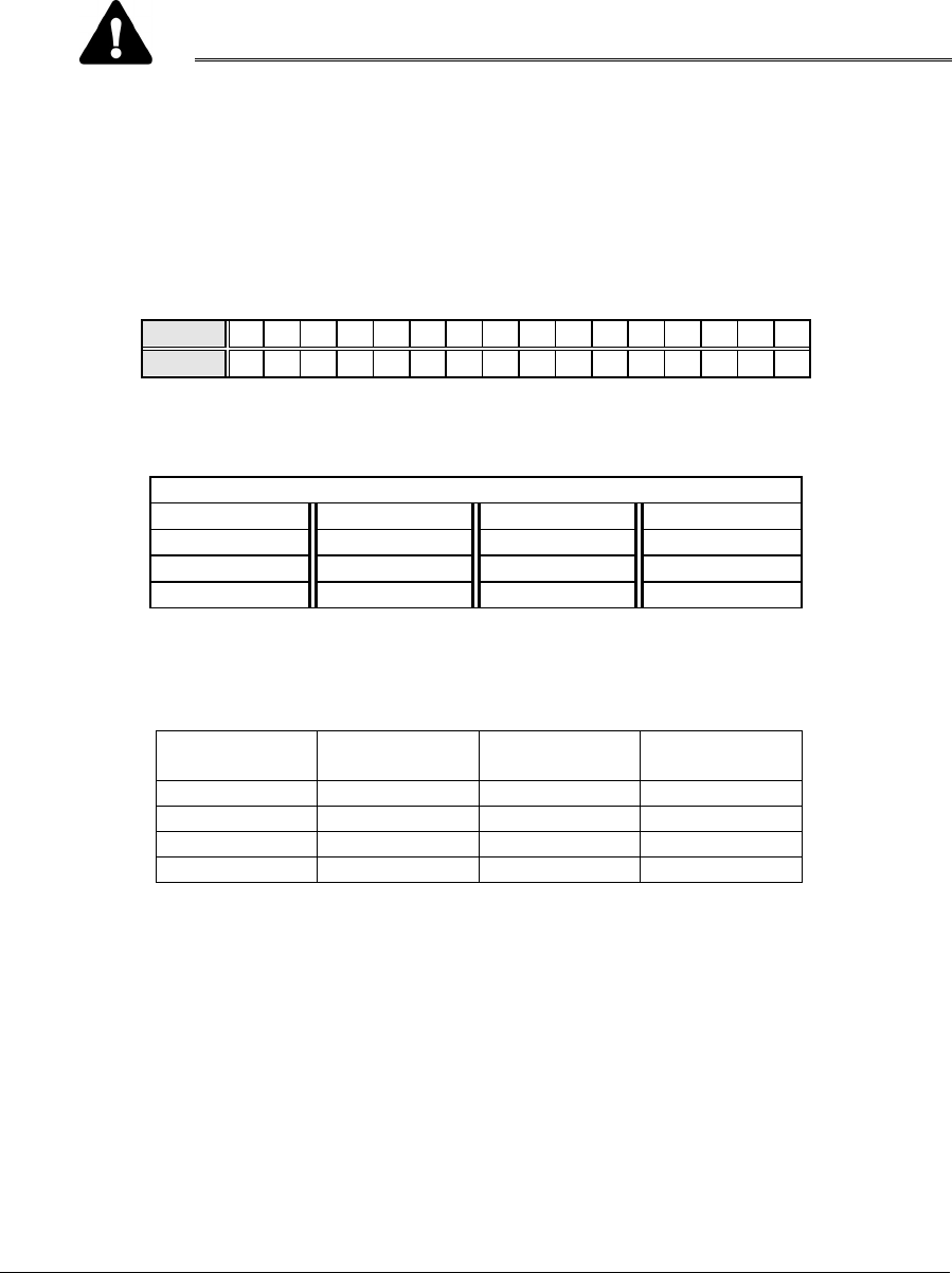
Table V-1
Beeps Address Beeps Address
1 113 9 121
2 114 10 122
3 115 11 123
4 116 12 124
5 117 13 125
6 118 14 126
7 119 15 127
8 120
VI. PROGRAMMING
A. USING THE LED KEYPAD
ACTION RESULT
ENTERING THE PROGRAM MODE
Enters the Program Mode.
Stay,Chime,Exit,Bypass &Cancel LEDS will flash.
[Go To Program Code]
Factory Default is
If the "Go To Program Code" is valid, the "Service"
LED will flash and the 5 function LEDs will illuminate
steady. You are now in the Program Mode and ready
to select the module address.
ENTERING THE MODULE ADDRESS
Scan a card. The card reader will address itself.
#
(example only)
Enters the module address. Refer to Table V-1 on
page 6 for the address assigned by the card reader
module itself.
The Armed LED will illuminate while it is waiting for a
programming location to be entered.
NX-1700E Card Reader 7
ACTION RESULT
PROGRAMMING A LOCATION
If an attempt is made to program an invalid entry for a particular segment, the
keypad sounder will emit a triple error beep (beep, beep, beep), and remain in
that segment awaiting a valid entry.
To Enter a Location:
[location] # The Armed LED will flash. If the location is valid, the
"Armed" LED will extinguish, the "Ready" LED will
illuminate, and the zone LED’s will show the data for
the first segment of this location.
To Change Location Data:
[changed data] The "Ready" LED will flash to indicate a data change
in process and will continue until the data is saved.
The new data is saved.
The keypad will increment and display the next
segment’s data.
NOTE: Repeat these steps until the last segment is reached.
To Exit a Location:
#Exits from this location. The “Ready” LED will
extinguish. The "Armed" LED will illuminate waiting for
a new programming location to be entered.
To Review The Data:
[location] # The Armed LED will flash. If the location number is
valid, the "Armed" LED will extinguish, the "Ready"
LED will illuminate, and the zone LEDs will show the
binary data for the first segment of this location.
(Do not enter data.)
The next segment is displayed. Each time ris
pressed, the data of the next segment will be displayed
for review.
Shortcuts: Previous location.
Same location.
Next sequential location.
EXITING THE PROGRAM MODE:
EXIT EXIT Exits this programming level.

NX-1700E Card Reader
8
B. USING THE LCD KEYPAD
All steps required for programming are the same as the aforementioned LED keypad. The LCD keypad
display will prompt you for the data required. While in the programming mode, and not in a location, the
number in parenthesis is the location you were previously changing. For example, if the display reads
"Enter location, then # (5)", it is reminding you that location 5 was the last location you programmed. In
feature selection data, the numbers of the enabled features will be displayed. The features not enabled
will display a hyphen (-).
C. PROGRAMMING DATA TYPES
a) Numerical Data
Numerical data can take on values from 0-255 or 0-15 depending on the segment
size.
b) Feature Selection
Feature selection data is used to turn features on or off.
VII. ADDING/DELETING USER CARDS
Adding and deleting users is done through a combination of entering information at the keypad and
scanning cards. Before a card can be entered, one reader on the system must be programmed with User
Card Programming enabled (Location 242, Segment 1, Option 1, page 11). It is recommended that only
one reader on the system be enabled to add/delete user cards and that this reader be located near a
keypad. This reader will transfer information to all other readers in the system once programming is
finished. Once a reader is enabled to add/delete users, it must be placed into one of the three following
modes: 1)AddOneUser;2) Add Multiple Users (or Add User w/ Auto-Increment), and 3) Delete One
User. Adding and/or deleting users on a card reader is similar to modifying user codes at a keypad.
MUST BE A MASTER USER IN ORDER TO ADD OR DELETE USERS.
ACTION RESULT
Accesses Code Programming
[master code]
Factory Default is
If the code is valid, the Ready LED will flash.
User Number 2 is used to program user cards, so…
if the control is an
NX-4, NX-6, or NX-8
if the control is
an NX-8E
Unit is now ready for you to choose one of the User
Card Programming modes (as if user code 2):
1) Add One User
2) Add Multiple Users (or Add User w/ Auto-
Increment)
3) Delete One User
IMPORTANT NOTE
Adding or deleting user cards from a reader causes the code for User Number 2 to become invalid.
Therefore, it will need to be reentered after all user cards are programmed into the readers.
ADDING ONE USER
To add a single user, enter [STAY] followed by the 3-digit “user number” if control is programmed for 4-
digit user codes or followed by [0]-[0] and the 3-digit “user number” if control is programmed for 6-digit
user codes. A total of 4 or 6 digits must be entered depending on the programming of the control panel;
the first being the [STAY] key, the last three being the “user number”. If a valid user number is entered,

NX-1700E Card Reader 9
LED1 on any enabled readers will begin to flash. Scan the card designated for the entered user. If the
user card is not already in the system, it will be added and mapped to the entered user number and
LED1 will stop flashing. If the card is already in the system, the reader will triple beep and LED1 will
continue flashing. After about 40 seconds, all the readers in the system will be updated with the new user
card information.
ADDING USER W/AUTO-INCREMENT
To add multiple users, enter [CANCEL] followed by the 3-digit “user number” of the first user to be
entered if control is programmed for 4-digit user codes or followed by [0]-[0] and the 3-digit “user
number” of the first user to be entered if control is programmed for 6-digit user codes. A total of 4 or 6
digits must be entered depending on the programming of the control panel; the first being the [CANCEL]
key, the last three being the “user number” of the first user to be entered. If a valid user number is
entered, LED1 on any enabled readers will begin to flash. Scan the card designated for the entered user.
If the user card is not already in the system, it will be added and mapped to the entered user number and
LED1 will continue flashing indicating that the next user card can be scanned for the next user number. If
the card is already in the system, the reader will triple beep and LED1 will continue flashing; the user
number is not incremented in this case. After about 40 seconds of no cards being scanned, all the
readers in the system will be updated with the new user card information.
DELETE ONE USER
To delete a single user, enter [EXIT] followed by the 3-digit “user number” if control
is programmed for 4-digit user codes or followed by [0]-[0] and the 3-digit “user
number” if control is programmed for 6-digit user codes. A total of 4 or 6 digits must
be entered depending on the programming of the control panel; the first being the
[EXIT] key, the last three being the “user number”. If a valid user number is entered,
LED1 on any enabled readers will begin to flash. Scan any card. The user card
information for the entered user number will be cleared and LED1 will stop flashing.
After about 40 seconds, all the readers in the system will be updated with the new
user card information.
VIII. PROGRAMMING LOCATIONS
LOCATION 0PROGRAMMING THE SCAN FUNCTIONS
(3 segments of binary data) Location 0 is used to select the particular function(s) that are activated when
a card is scanned. More than one function may be selected. If more than one function is selected, they
will execute in order from function 1 to function 8.
Segment 1 Single Scan Function
Program the functions that are performed when a card is scanned once.
LED 1 - "On" to send Code Entry function to the control panel. (Default is “On”)
LED 2 - "On" to activate the Armed Away mode.
LED 3 - "On" to activate the Armed Stay mode.
LED 4 - "On" to send the Disarm function to the control panel.
LED 5 - "On" to send Auxiliary Function #1 to the control panel.
LED 6 - "On" to send Auxiliary Function #2 to the control panel.
LED 7 - "On" to broadcast an X-10 function (see Location 241 for programming).
LED 8 - "On" to activate the relay driver output.
Segment 2 Double Scan Function
Program the functions that are performed when a card is scanned twice within the 2 Scan Hold Time
(Location 244, Segment 1). The descriptions of the options are the same as for Single Scan Function.
(Default is 1)
If an
individual
keeps the
card,itcan
still be
deleted.
NX-1700E Card Reader
10
Segment 3 Single Scan Hold Function
Program the functions that are performed when a card is scanned and held at the reader for the duration
of the 2 Scan Hold Time (Location 244, Segment 1). The descriptions of the options are the same as for
Single Scan Function. (Default is 1)
LOCATIONS 1 - 240 SERIAL NUMBERS MAPPING USER CARDS TO USERS
(8 segments of hexadecimal data)
DO NOT EDIT LOCATIONS 1- 240. YOU MAY LOSE THE ABILITY TO
SCAN A CARD!!
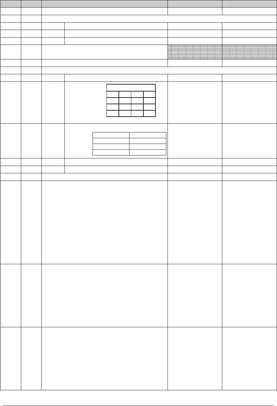
LOCATION 241 PROGRAMMING THE X-10 ADDRESS FOR THE SCAN FUNCTIONS
(5 segments of numerical data)
Segment 1
Program a number from 0-15 to represent the corresponding X-10 Module Number from the following
table. (Default is 0)
Module 12 3 4 5 6 7 8 9 10111213141516
Seg 1 01 2 3 4 5 6 7 8 9 10 11 12 13 14 15
Segment 2 Program a number from 0-15 to represent the corresponding X-10 House code from the
following table. (Default is 0)
X-10 ADDRESS CODES
0=A 4=E 8=I 12=M
1=B 5=F 9=J 13=N
2=C 6=G 10=K 14=O
3=D 7=H 11=L 15=P
Segment 3 Single Scan Function
Program the X-10 function that is performed when a card is scanned once. This location only needs to
be programmed if Location 0, Segment 1, Option 7 is set. Use the following table. (Default is 2)
Function # Function
performed Function # Function
performed
0 All units off 4 Dim
1 All lights on 5 Bright
2On6 All lights off
3 Off All others Reserved
Segment 4 Double Scan Function
Program the X-10 function that is performed when a card is scanned twice within the 2 Scan Hold Time
(Location 244, Segment 1). The descriptions of the function codes are the same as for Single Scan
Function. This location only needs to be programmed if Location 0, Segment 2, Option 7 is set. Use the
above table. (Default is 3)
Segment 5 Single Scan Hold Function
Program the X-10 function that is performed when a card is scanned and held at the reader for the
duration of the 2 Scan Hold Time (Location 244, Segment 1). The descriptions of the function codes are
the same as for Single Scan Function. This location only needs to be programmed if Location 0,
Segment 3, Option 7 is set. Use the above table. (Default is 2)

NX-1700E Card Reader 11
LOCATION 242 PROGRAMMING THE OPTIONS AND READER PARTITION
(4 segments of binary data)
Segment 1 System Options:
LED1 - "On" if reader is enabled for User Card Programming.
LED2 - "On" if optical tamper is enabled. (Default is “On”)
LED3 - "On" if reader buzzer is to follow typical keypad buzzing.
LED4 - "On" if ding-dong chime enabled (dependent on option 3 and chime being enabled).
LED5 - “On” if relay driver function is to be logged as Code Entry.
LED6 - Reserved.
LED7 - Reserved.
LED8 - Reserved.
Segment 2 LED1 (Green) Options:
LED1 - "On" to follow Ready status of system. (Default is “On”)
LED2 - "On" to toggle with the Relay Driver activation. (Default is “On”)
LED3 - "On" if inverted.
LED4 - Reserved.
LED5 - Reserved.
LED6 - Reserved.
LED7 - Reserved.
LED8 - Reserved.
Segment 3 LED2 (Red) Options:
LED1 - "On" to follow Armed status of system. (Default is “On”)
LED2 - "On" to toggle with the Relay Driver activation.
LED3 - "On" if inverted.
LED4 - Reserved.
LED5 - Reserved.
LED6 - Reserved.
LED7 - Reserved.
LED8 - Reserved.
Segment 4 Reader Partition:
LED1 - "On" if reader is in Partition 1. (Default is “On”)
LED2 - "On" if reader is in Partition 2. (Default is “On”)
LED3 - "On" if reader is in Partition 3. (Default is “On”)
LED4 - "On" if reader is in Partition 4. (Default is “On”)
LED5 - "On" if reader is in Partition 5. (Default is “On”)
LED6 - "On" if reader is in Partition 6. (Default is “On”)
LED7 - "On" if reader is in Partition 7. (Default is “On”)
LED8 - "On" if reader is in Partition 8. (Default is “On”)
LOCATION 243 PROGRAMMING THE DOOR PROP ZONE
(1 segment of numerical data)
Enter the zone number that will be monitored for sounding the Door Prop Alarm. Program a 0 (default) to
disable this function. See Location 244, Segment 3 for the length of time the zone is monitored before
sounding the alarm. This location must be programmed with a valid zone in order for a Door Control
Module, if installed, to work properly. (Default is 0)

NX-1700E Card Reader
12
LOCATION 244 PROGRAMMING THE VARIOUS READER TIMERS
(3 segment of numerical data)
Segment 1 2 Scan Hold Time
Enter the amount of time allowed for a double scan to be detected and the amount of time required to
hold a card to activate the functions programmed in Location 0, Segments 2 and 3. This timer is timed in
1/100 second increments from 0 to 2.55 seconds. (Default is 75 = ¾ second).
Segment 2 Relay Active Time
Enter the amount of time the Relay Driver is energized once activated. This timer is timed in 1/10 second
increments from 0 to 25.5 seconds. (Default is 50 = 5 seconds).
Segment 3 Door Prop Time
Enter the amount of time a monitored zone (see Location 243) must be faulted before sounding an alarm
(local buzzer). This timer is timed in 1-second increments from 0 to 255 seconds. (Default is 10 =10
seconds).
LOCATION 245 RESETTING THE READER ADDRESS
(1 segment of numerical data) If it is necessary to reset the address of the reader, enter a 0 in this
location. This will cause the reader to cease functioning. If a card is scanned with the system in
Program Mode, the reader will again find an available address and set itself, beeping back
to the user the address that was found as per the table on page 6. If the system is not in
Program Mode and a card is scanned at a reader with a reset address, then it will sound
an error beep.
NX-1700E Card Reader 13
IX. PROGRAMMING WORKSHEETS
LOC PG DESCRIPTION DEFAULT DATA
09 SINGLE SCAN FUNCTION
Seg
1 Single Scan Function 1
2 Double Scan Function 1
3 Single Scan Hold Function 1
1-
240 10 Card Serial Numbers
Do not edit these locations!
241 10 X-10 ADDRESS
Seg
1 Module Number 0
2 House Code 0
3 Single Scan Function 2
4 Double Scan Function 3
5 Single Scan Hold Function 2
242 11 OPTIONS AND READER PARTITION
Segment 1 – System Options 2
1= "On" if enabled for User Card
Programming
2= "On" if optical tamper enabled
3= "On" if buzzer follows keypad buzzing
4= "On" if ding-dong chime enabled (Opt 3
& chime must be enabled)
5= “On” if relay driver function logs as
Code Entry
6= Reserved
7= Reserved
8= Reserved
Segment 2 – LED1 (Green) Options 1,2
1= "On" follows system Ready status
2= "On" to toggle with the Relay Driver
3= "On" if inverted
4= Reserved
5= Reserved
6= Reserved
7= Reserved
8= Reserved
Segment 3 – LED2 (Red) Options 1
1= "On" follows system Armed status
2= "On" to toggle with the Relay Driver
3= "On" if inverted
4= Reserved
5= Reserved
6= Reserved
7= Reserved
8= Reserved
X-10 ADDRESS CODES
0=A 4=E 8=I 12=M
1=B 5=F 9=J 13=N
2=C 6=G 10=K 14=O
3=D 7=H 11=L 15=P
0=All units off 4=Dim
1=All lights on 5=Bright
2=On 6=All lights off
3=Off Other=Reserved

NX-1700E Card Reader
14
LOC PG DESCRIPTION DEFAULT DATA
Segment 4 – Reader Partition 1,2,3,4,5,6,7,8
1= "On" if reader is in Partition 1
2= "On" if reader is in Partition 2
3= "On" if reader is in Partition 3
4= "On" if reader is in Partition 4
5= "On" if reader is in Partition 5
6= "On" if reader is in Partition 6
7= "On" if reader is in Partition 7
8= "On" if reader is in Partition 8
243 11 DOOR PROP ZONE 0 = Disabled
244 12 Seg
1 2 Scan Hold Time (1/100 seconds) 75 = 3/4 second
2 Relay Active Time (1/10 seconds) 50 = 5 seconds
3 Door Prop Time (seconds) 10 = 10 seconds
245 12 RESET THE READER ADDRESS
Entering a “0” will reset and cause the
reader to cease functioning.
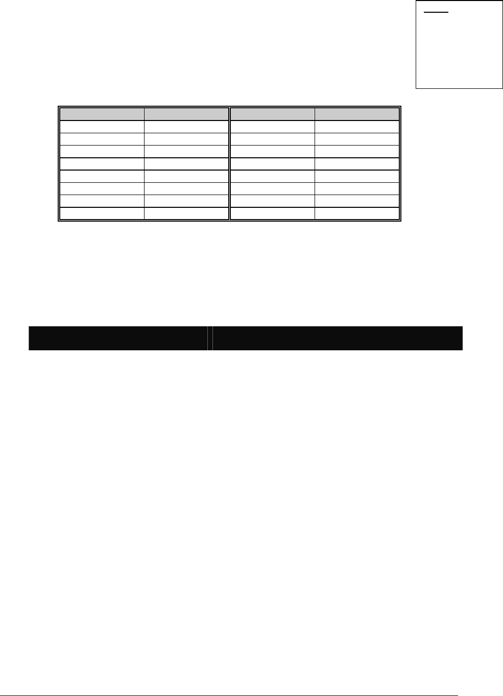
X. ORDERING INFORMATION
PART # DESCRIPTION PART # DESCRIPTION
NX-1700E Card Reader Module NX-108E 8 Zone LED Keypad
NX-8E 8 – 192 Zone Control Only NX-116E 16 Zone LED Keypad
NX-8E-KIT NX-8E Control, NX-108E LED Keypad,
40VA Transformer NX-124E 24 Zone LED Keypad
NX-8 8 – 48 Zone Control Only NX-148E Alphanumeric LCD Keypad
NX-8-KIT NX-8 Control, NX-108E LED Keypad,
40VA Transformer NX-1192E 192 Zone LCD Keypad
NX-6 6 – 12 Zone Control Only NX-1208E 8 Zone LED Keypad
NX-6-KIT NX-6 Control, NX-108E LED Keypad,
40VA Transformer NX-1248E 48 Zone LCD Keypad
NX-4 4 Zone Control Only NX-1308E 8 Zone LED Door Design Keypad
NX-4-KIT NX-4 Control, NX-108E LED Keypad,
40VA Transformer NX-1316E 16 Zone LED Door Design Keypad
NX-216E 16 Zone Expander Module NX-1324E 24 Zone LED Door Design Keypad
NX-320E Smart Power Supply and Buss Extender NX-1448E 48 Zone Fixed Language Icon Keypad
NX-408E 8 Zone Wireless Expansion Module NX507E Seven Relay Module
NX-416E 16 Zone Wireless Expansion Module NX-508E Eight Output Module
NX-448E 48 Zone Wireless Expansion Module NX-534E Two-Way Listen In Module
NX-540 "Operator II" Telephone Interface
NX-591E Cellemetry Interface

NX-1700E Card Reader 15
XI. FCC INFORMATION
This device complies with Part 15 of the FCC rules. Operation is subject to the following three
conditions:
1. This device may not cause harmful interference.
2. This device must accept any interference received, including interference that may cause
undesired operation.
3. Changes or modifications not expressly approved by the party responsible for compliance
could void the user’s authority to operate the equipment.
FCC ID: CGGNX-1700E
NOTES

NX-1700E Card Reader
16
XII. SPECIFICATIONS
DIMENSIONS Approx. 1.5"W x 4.5"L x 1"D with 6’ cable
OPERATING POWER 12 VDC, Supplied by NX-4, NX-6, NX-8,
NX-8E, or NX-320E
CURRENT DRAW 40mA Standby with Green LED
110mA Maximum
OPERATING TEMPERATURE 32 to 120 degrees F
SHIPPING WEIGHT < 1 lb.
GE INTERLOGIX
1420 N. MAIN STREET
GLADEWATER, TEXAS 75647
Main 800-727-2339 Technical Support 800-727-2339
Outside the US 903-845-6941 Tech Support Fax 903-845-8409
Main Fax 903-845-6811 Sales & Literature 800-547-2556
Revision B (October 2002)