UTStarcom Korea Technologies UTS-ACS-40 Wireless Local Loop User Manual 413407
UTStarcom Korea Technologies Ltd. Wireless Local Loop 413407
UserManual.wiki
>
UTStarcom Korea Technologies
>
UTS ACS 40 User Manual
users manual
Navigation menu
Upload a User Manual
Namespaces
Wiki Guide
HTML
PDF
Info
Views
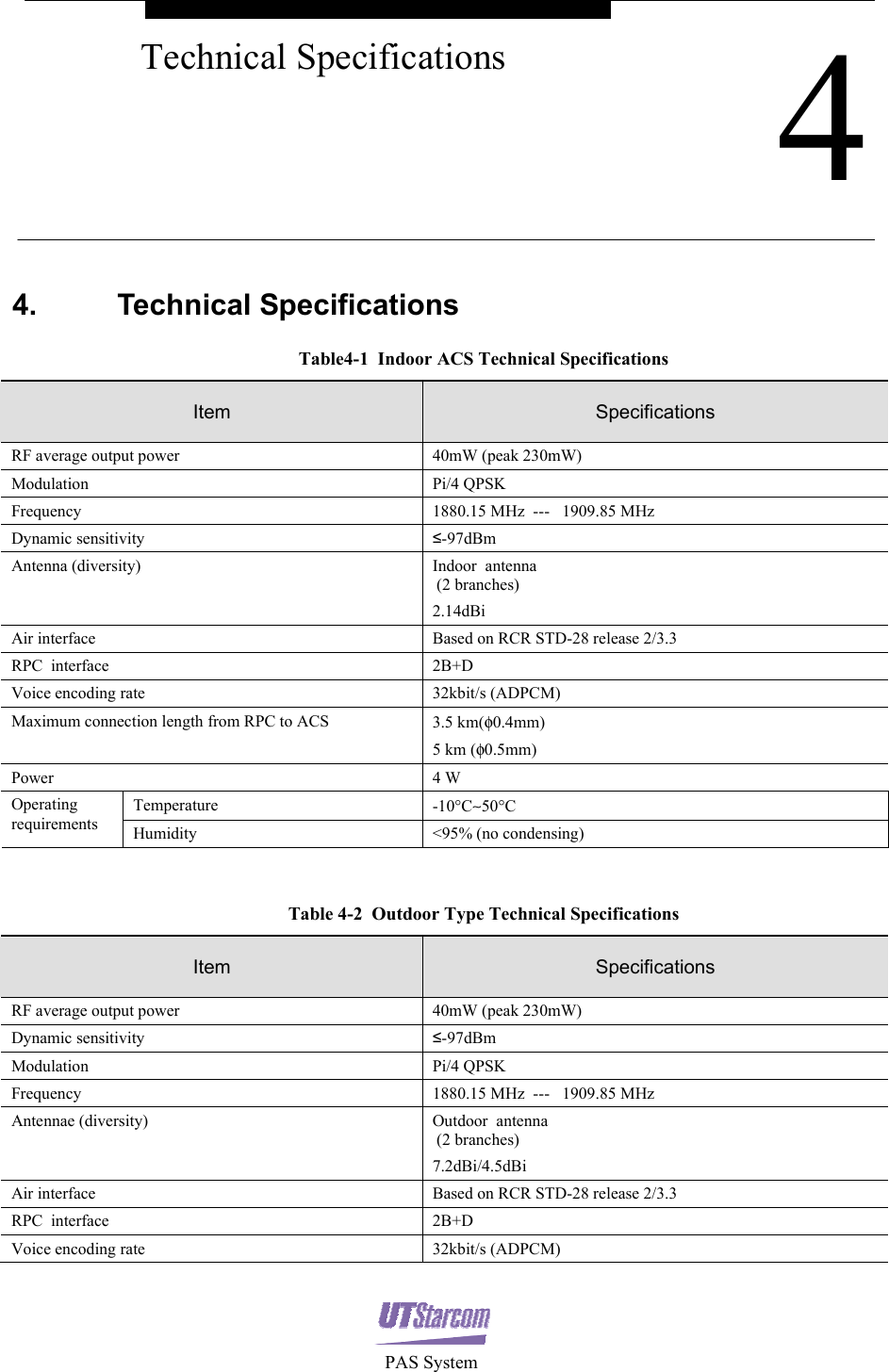
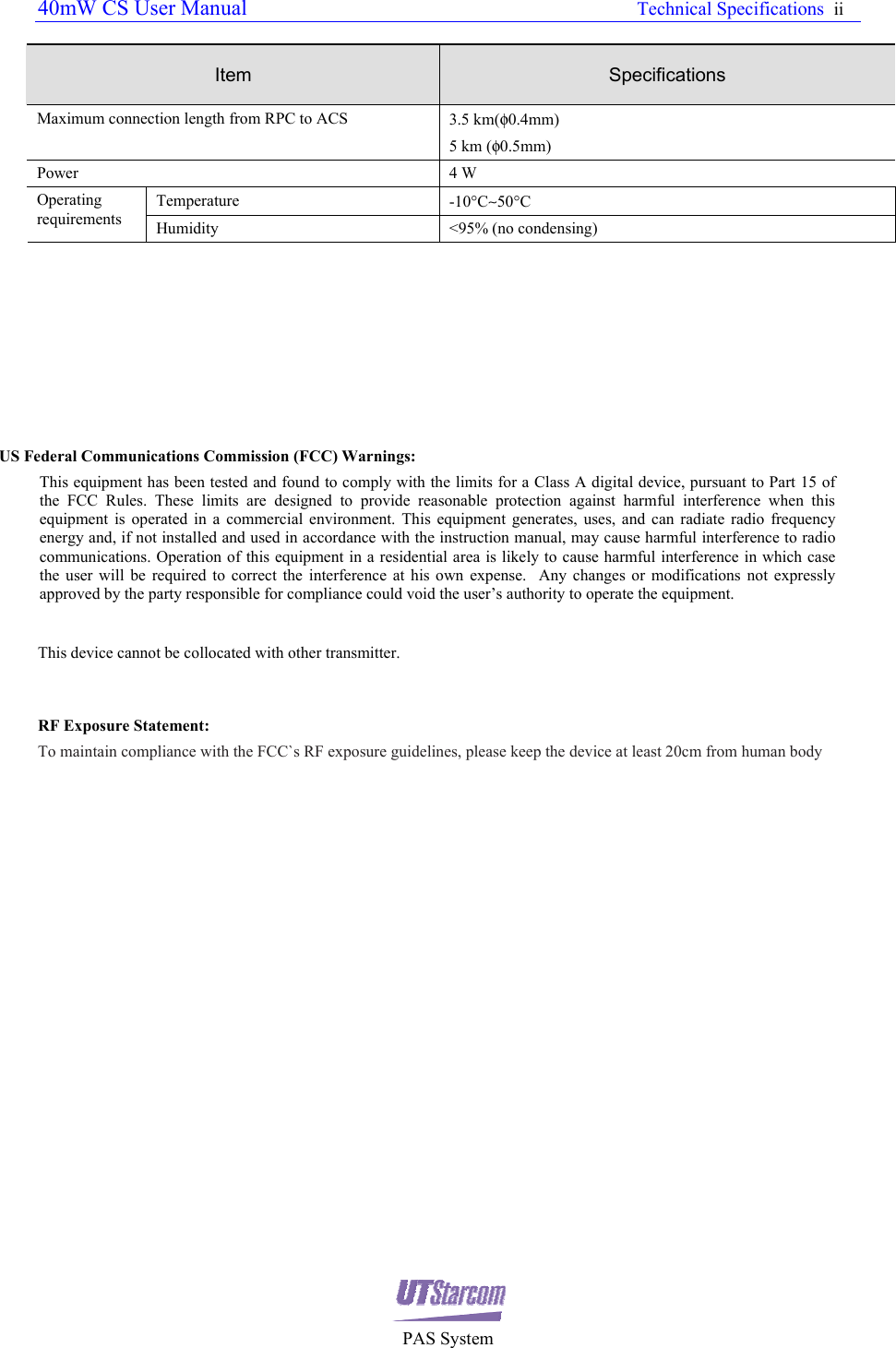
User Manual
Discussion / Help
Navigation