UTStarcom Korea Technologies UTS-ACS-40 Wireless Local Loop User Manual 413407
UTStarcom Korea Technologies Ltd. Wireless Local Loop 413407
users manual

User’s Manual
January, 2003
- i -
Definition & Acronyms
ACS Adaptive Cell Station
ADPCM Adaptive Differential Pulse Code Modulation
ATC Air Traffic Controller
BRI Basic Rate Interface
CCM CS Control Module
CDR Call Description Record
CO Central Office
CS Cell Station
RPC CS Controller
CSIF CS Interface Module
DDF Digital distributed Frame
DTMF Dual Tone Multi Frequency
DWRT Data Wireless Remote Terminal
E1-IF E1 Interface Module
E1MW W1 Module Wireless
EBAM Extension Bus Adapter Module
ECNT Enhanced Main Control Card
FDDI Fiber Distributors Data Interface
FSK Frequency Shift Keying
FSU Fixed Subscriber Unit
FXOW Foreign exchange Office Wireless
GND Ground
HGND Protection Ground or High-voltage Ground
HLR Home Location Register
IP Internet Protocol
LE Local Exchange
LED Light Emitting Diode
MCU Monitor and Control Unit
MDF Main Distributed Frame
NMS Network Management System
OAM&P Operation Administration Maintenance and Provisioning
PAS Personal Access System
PC Personal Computer
PDP Power Distribution Panel
PGT PAS Gateway Terminal
PGTC PAS Gateway Terminal-Central
PGTS PAS Gateway Terminal-Satellite
PHS Personal Hand phone System
PIAFS PS-PHS Internet Access Forum Specification
PS Personal Station
PSM Power Supply Module
PSTN Public Switched Telephone Network
QFE Quad Fast Ethernet Card
RCM Roaming Control Module
RF Radio Frequency
RP Radio Port
RPC Radio Port Controller
RP-IF RP Interface Module
RT Remote Terminal
RX Receiving Data
RxD Receive Data
SATC Server-based ATC
SCMW System Control Module Wireless
TCM Traffic Control Module
TE1M Traffic E1 Module
TX Transmitting Data
TxD Transmit Data
VLR Visitor Location Register

PAS System
1
Overview
1. Overview
ACS (Adaptive Cell Station, i.e. ACS) is a kind of wireless equipment. The
ADPCM signals from the RPCACS controller enter into the standard 2B+D
interface via twisted pair wire; The signals are transmitted in the form of radio
frequency modulation wave, which makes up a wireless link between the ACS
and PS (Personal Station). The link provides voice/data communications to
terminal subscribers via RPC, central terminal equipment and central switch
office. In terms of wireless communication, the ACS provides RCR STD-28 air
interface.
It applies Time Division Multiple Access (TDMA) and Time Division Duplex
(TDD) techniques. Each individual radio link between the ACS and FSU/PS is
assigned 1 time slot for a control channel (C-Ch) and 3 time slots for traffic
(speech) channels (T-Chs). The C-channel time slot of RCR STD-28 does not
need to be specially located, so, in the system, any one of the 4 time slots can be
selected as the control time slot.
PAS System
2
ACS Type
2. ACS Type
In terms of the installation environment, ACSs are sorted into Indoor ones and
Outdoor ones.
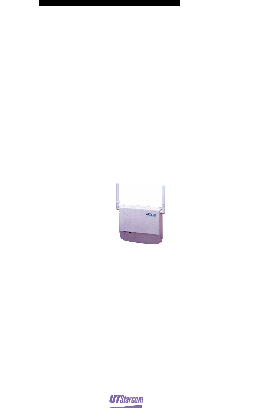
2.1 Indoor ACS
Indoor ACS is installed in the wall and ceiling of the place like hotel, government
building, bank. It provides the services of PS, telephone and data terminal in the
building. It has two antennas that are connected with the main body.
The indoor ACS is shown in Figure 2-1.
Figure 2-1 indoor ACS
2.2 Outdoor ACS
As per the number of ACSs connected, Outdoor ACSs can be sorted into Singe-
ACS outdoor type and 4-ACS outdoor type.
2.2.1 Singe-ACS outdoor type
Singe-ACS outdoor type is usually installed on sidewall, top of the building. It is
waterproof, need not to be maintained which has with high reliability. Its antennas
are usually placed at high positions, so that the coverage area can be relatively
larger.
This type of ACS is line-powered over ordinary twisted-pair cabling from RPC,
so no joint box is needed. It adopts 2-antennas diversity. Please refer to Chapter 4
for detailed information.
The Singe-ACS outdoor type is shown in Figure 2-2.
ACS User Guide ACS Type ii
PAS System
Figure 2-2 Singe-ACS outdoor type
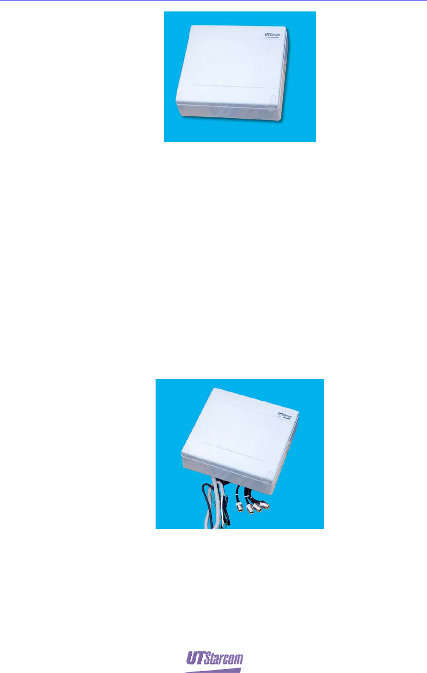
2.2.2 4-ACS outdoor Type
For this type of ACS, 4 single-ACSs are placed in a waterproof case. It adopts
group control mode as well as 4-antennae diversity.
These ACSs are usually installed on pole, top of the building. The antennae of 4-
ACS outdoor are generally placed at high positions, so that the coverage area can
be relatively larger. It is also waterproof, need not to be maintained which has
with high reliability.
This type of ACS is line-powered over ordinary twisted-pair cabling from RPC,
so no joint box is needed. It adopts 4-antennas diversity. Please refer to Chapter 4
for detailed information.
The 4-ACS outdoor type is shown in Figure 2-3.
Figure 2-3 4-ACS outdoor Type
2.3 ACS Antenna
The ACS adopts omni-directional antenna or other kind of antenna. Details of the
ACS antenna capabilities are depicted in its technical specifications.
PAS System
3
Technical Introduction
3. Technical Introduction
3.1 ACS Coverage Range
For ACS installation, the quantity and distribution of ACSs are affected by the
factors below:
z Geographical condition of the service area
z Subscriber distribution in the service area
z Expected traffic and service quality
3.1.1 Wireless Signal Transmission Mode
The frequency range of the PAS system is 1.9GHz which belongs to WIRELESS
LOCAL LOOP system; the wavelength is about 16cm, which is far shorter than
the building. The electric wave is poor at diffraction; the direct wave and reflect
wave are more intense than the diffraction wave. Figure3-1 shows the direct and
reflect of the electric wave in the urban area, where buildings are concentrated.
Figure3-1 Transmission Mode in Urban Area
The ACS coverage range in urban area is different from that in suburban area.
Moreover, the ACS coverage range is also influenced by the antenna height; the
higher is the antenna, the wider is the coverage range.
40mW ACS User Guide Technical Introduction ii
PAS System
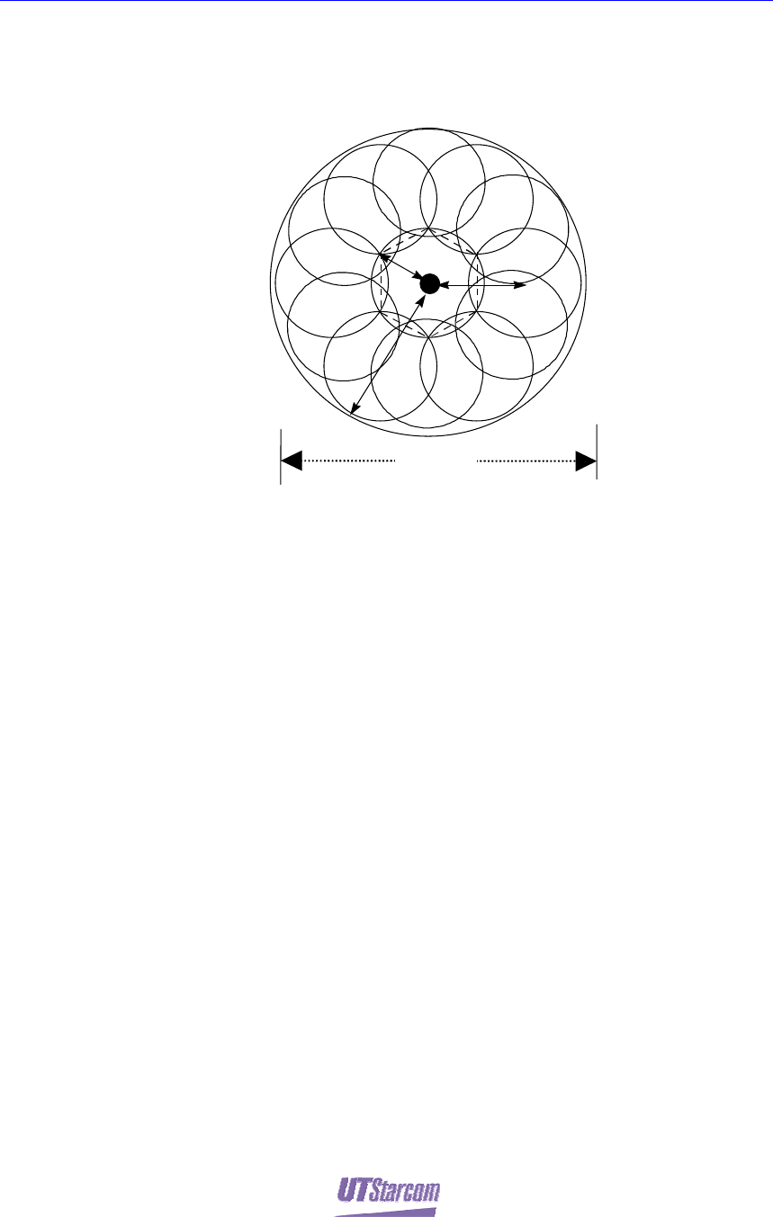
3.1.2 Micro-zone Overlap
The service will be the best if ACSs are installed as per the micro-zone overlap
structure.
2 Km
3.5-5 Km
5.5 -7 Km
A
bout 14K
m
Figure3-2 Coverage Area in Micro-zone Overlap Structure
The application of micro-zone overlap and dynamic channel allocation makes the
system more flexible and enlarges the system capacity. Because the ACSs are
installed considering coverage overlapped, subscribers can use all the channels
while calling or called. Thus, the micro-zone overlap structure enhances the
system reliability and quality of service. Even if a ACS is broken down, the
system capacity will not be affected. Due to its dynamic channel allocation,
operators’ requirements can be easily satisfied without frequency planning, which
is also convenient for expansion.
40mW ACS User Guide Technical Introduction iii
PAS System
3.2 Traffic Management
3.2.1 Stand-alone ACS
In the case of an isolated ACS there are 4 time slots installed for radio links. One
slot is a control channel for signaling and the other three are traffic channels. The
number of accommodated subscribers in that ACS covering the zone calculated
according to the Erlang-B model is as follows:
Erlang per zone: (3 T-chs, GOS=5%) = 0.899 Er
Subscribers (FSU or PSs): (0.899 ÷ 0.05) = 18 Subscribers
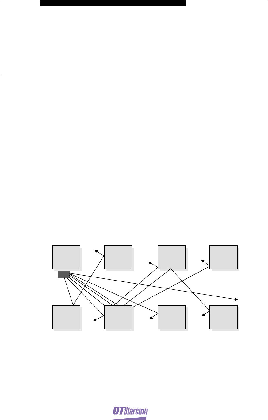
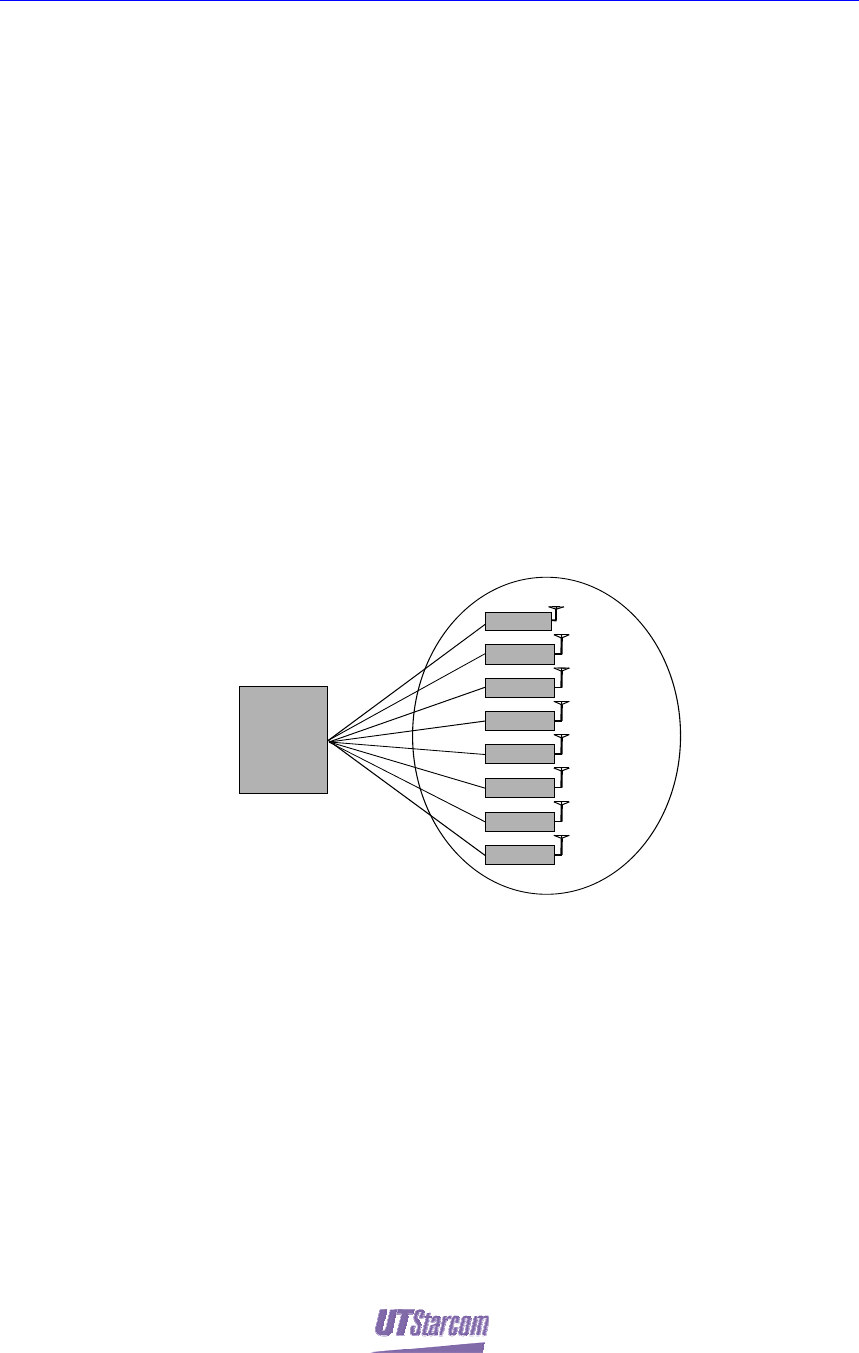
3.2.2 Group controlled ACSs
Using a group configuration, up to eight ACSs in the same group share one
Control Channel, which is useful for high traffic areas. One master ACS can
control a maximum of seven slave ACSs in the same area. The master ACS has
one control channel while the left 31 channels of these 8 ACSs are for traffic
channels.
RPC
Cchx 1
Zone
8 ACSs
Group Control Operation
Slave
Tchx 3
Tchx 4
Master
Slave Tchx 4
Slave Tchx 4
Slave Tchx 4
Slave Tchx 4
Slave Tchx 4
Slave Tchx 4
Figure3-3 Group Control ACSs
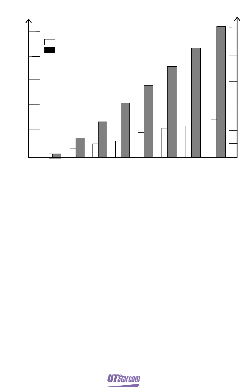
In an eight ACSs group control mode, the number of accommodated subscribers
in the group control coverage zone is calculated in accordance with the Erlang-B
model as follows:
z Erlang per zone : (31 T-chs, GOS=5%) = 25.773 Er
z Subscribers (FSU or PSs): (25.773 ÷ 0.05 ) = 515 Subscribers
The comparison for the number of accommodated subscribers between the group
controlled ACSs and non-group ACSs is shown in Figure3-4.
40mW ACS User Guide Technical Introduction iv
PAS System
Subscribers
Erlang
Traffic Capacity
Number of ACS
10
5
6
300
200
100
8
4
0.899(erl)
18 Subs
£º
Non-group Control Operation
£º
Group Control Operation
Note£º
GOS = 5%
0.05Er/Subscriber
2
1 3 5 7
50
400
500
0
15
20
25
1.798(erl)
36 Subs
3.988(erl)
80 Subs 2.697(erl)
54 Subs
7.076(erl)
141 Subs
3.596(erl)
72 Subs.
14.31(erl)
286 Subs.
4.495(erl)
90 Subs.
10.633(erl)
213 Subs.
5.394(erl)
108 Subs.
18.08(erl)
361 Subs.
6.293(erl)
126 Subs.
7.197(erl)
144 Subs.
21.094(erl)
422 Subs.
25.723(erl)
515 Subs.
Figure3-4 Subscribers per ACS in Group and Non-group Control
The deployment of ACSs are decided by the subscribers distribution:
z In the area consist of clusters of small populations. Non-group method (i.e.
Stand-alone ACS control mode) is introduced to use.
z In the area of high-density populations. Group control mode is highly
recommended to use.
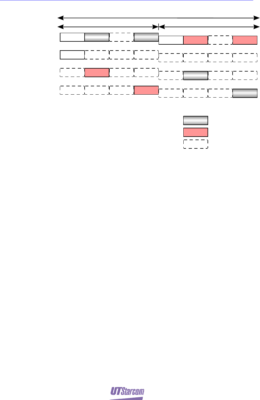
3.3 Air Interface
Each ACS provides one C-channel and 3 T-channels.
40mW ACS User Guide Technical Introduction v
PAS System
TDMA-TDD Frame (5ms)
CS Transmission PHS PS Transmission
CS
PHS
PS #2
PHS
PS #3
PHS
PS #1
CCH T2 T4
CCH
R4
R2 T2
R2
CCH R4
T4
CCH: signaling channel
T2,T4: communication channel (to transmit)
R2,R4: communication chanenl (to receive)
PAS Handset #1: signaling channel, waiting
PAS Handset #2: 2nd time slot, calling
PAS Handset #3: 4th time slot, calling
T2
R2
: transmission time slot
: receivin
g
time slot
: idle time slot
R2
R4
R4
R4
R2
Figure3-5 Wireless Channel Frame Structure
The radio frequency channel allocation diagram shown in Figure3-5 depicts a
typical wireless channel structure, where, 3 subscribers can communicate in single
ACS control mode.
The channels are not preassigned; channels are allocated automatically by a
dynamic channel allocation system. It is an outstanding feature of the PAS system.
With a settled algorithm, the system dynamically chooses a frequency from the
available frequency resources as the communication carrier frequency, and timely
adjusts the frequency as per the signal disturbance. In this sense, the PAS system
is a slow frequency-hopping system.
3.4 Synchronization Technology
The ACS in the system adopts air synchronization technology. Master ACS
synchronizes with other master ACSs via GPS. By receiving the air
synchronization signal from master ACS, slave ACS synchronize with master
ACS. For RPC synchronization solution, please refer to “GSG2 user guide”.
3.5 Self-Adaptive Mode
ACS is a kind of self-adaptive CS, which can adjust its transmission power. The
transmission power ranged from 0mW to 200 mW can be adjusted on-line.
3.6 ACS Operation Mode
ACS adopts the sending after detecting operation mode (receiving then sending).
Before sending signals, ACS detects the utilization of the surrounding
WIRELESS LOCAL LOOP radio channels. According to the signal strength of

40mW ACS User Guide Technical Introduction vi
PAS System
the occupied channel, ACS will appropriately assign the new voice channels. The
unoccupied channels and channels with low signal strength are preferred to be
taken as the new voice channels. Thus, the newly built WIRELESS LOCAL
LOOP system will not affect the normal running of other systems. Moreover, the
new system can easily come into use, so that the limited WIRELESS LOCAL
LOOP frequency resources can be exploit scientifically and reasonably.
PAS System
4
Technical Specifications
4. Technical Specifications
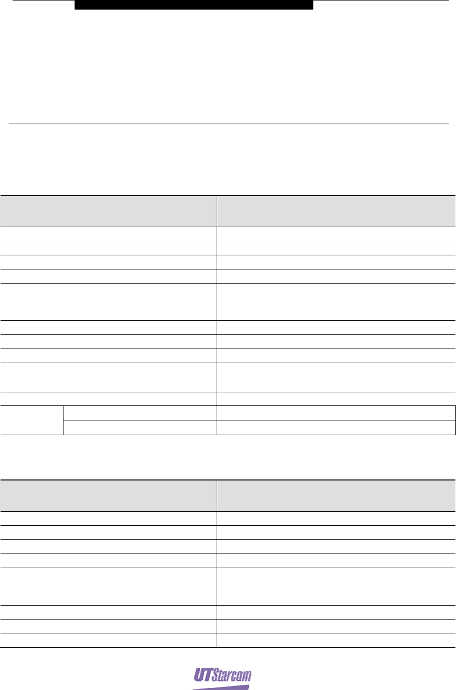
Table4-1 Indoor ACS Technical Specifications
Item Specifications
RF average output power 40mW (peak 230mW)
Modulation Pi/4 QPSK
Frequency 1880.15 MHz --- 1909.85 MHz
Dynamic sensitivity ≤-97dBm
Antenna (diversity) Indoor antenna
(2 branches)
2.14dBi
Air interface Based on RCR STD-28 release 2/3.3
RPC interface 2B+D
Voice encoding rate 32kbit/s (ADPCM)
Maximum connection length from RPC to ACS 3.5 km(φ0.4mm)
5 km (φ0.5mm)
Power 4 W
Temperature -10°C∼50°C
Operating
requirements Humidity <95% (no condensing)
Table 4-2 Outdoor Type Technical Specifications
Item Specifications
RF average output power 40mW (peak 230mW)
Dynamic sensitivity ≤-97dBm
Modulation Pi/4 QPSK
Frequency 1880.15 MHz --- 1909.85 MHz
Antennae (diversity) Outdoor antenna
(2 branches)
7.2dBi/4.5dBi
Air interface Based on RCR STD-28 release 2/3.3
RPC interface 2B+D
Voice encoding rate 32kbit/s (ADPCM)

40mW CS User Manual Technical Specifications ii
PAS System
Item Specifications
Maximum connection length from RPC to ACS 3.5 km(φ0.4mm)
5 km (φ0.5mm)
Power 4 W
Temperature -10°C∼50°C
Operating
requirements Humidity <95% (no condensing)
US Federal Communications Commission (FCC) Warnings:
This equipment has been tested and found to comply with the limits for a Class A digital device, pursuant to Part 15 of
the FCC Rules. These limits are designed to provide reasonable protection against harmful interference when this
equipment is operated in a commercial environment. This equipment generates, uses, and can radiate radio frequency
energy and, if not installed and used in accordance with the instruction manual, may cause harmful interference to radio
communications. Operation of this equipment in a residential area is likely to cause harmful interference in which case
the user will be required to correct the interference at his own expense. Any changes or modifications not expressly
approved by the party responsible for compliance could void the user’s authority to operate the equipment.
This device cannot be collocated with other transmitter.
RF Exposure Statement:
To maintain compliance with the FCC`s RF exposure guidelines, please keep the device at least 20cm from human body