UTStarcom Korea Technologies UTS-EA7T56B Wireless Local Loop Phone System User Manual 2 General Description
UTStarcom Korea Technologies Ltd. Wireless Local Loop Phone System 2 General Description
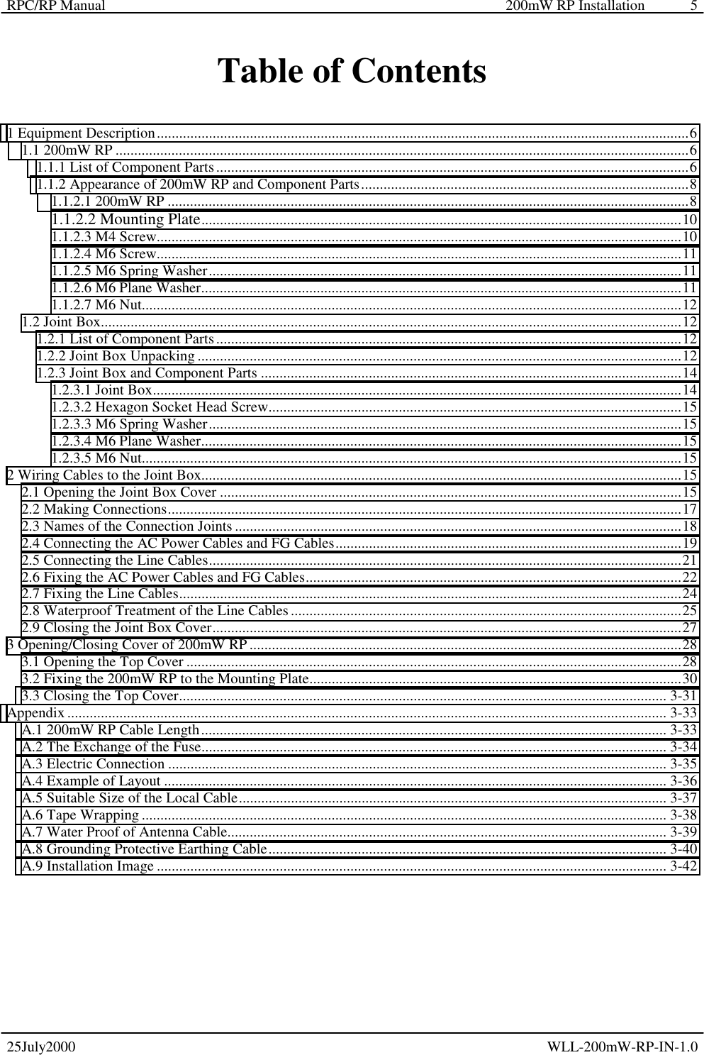
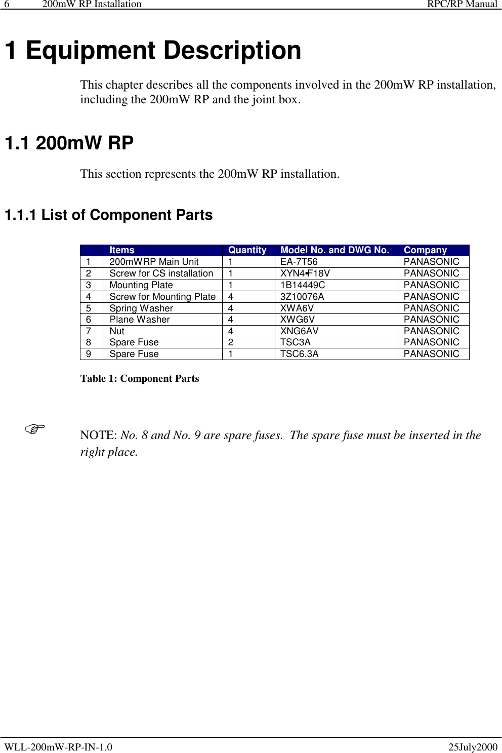
Contents
- 1. Install Manual
- 2. Users Manual
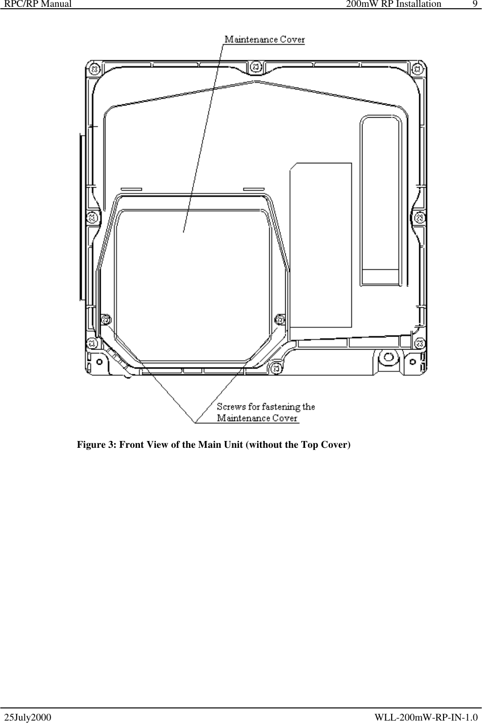
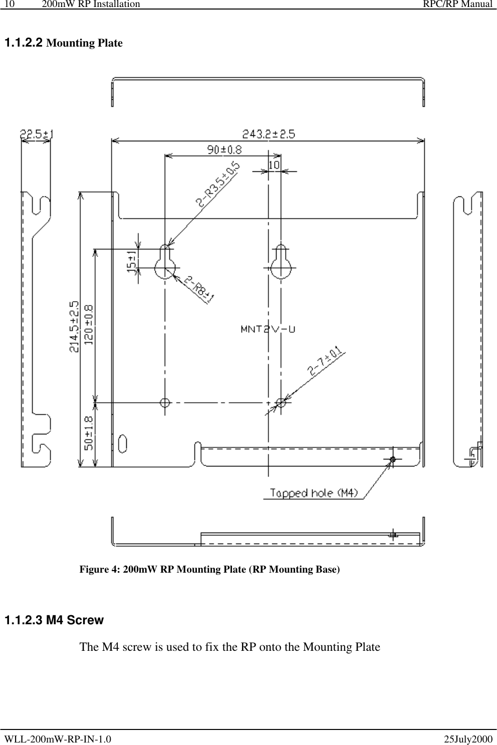
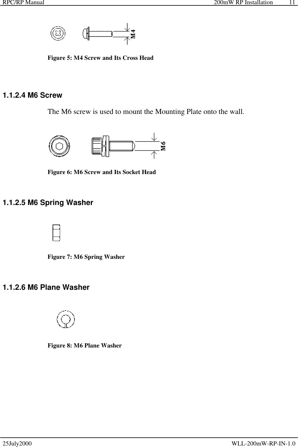
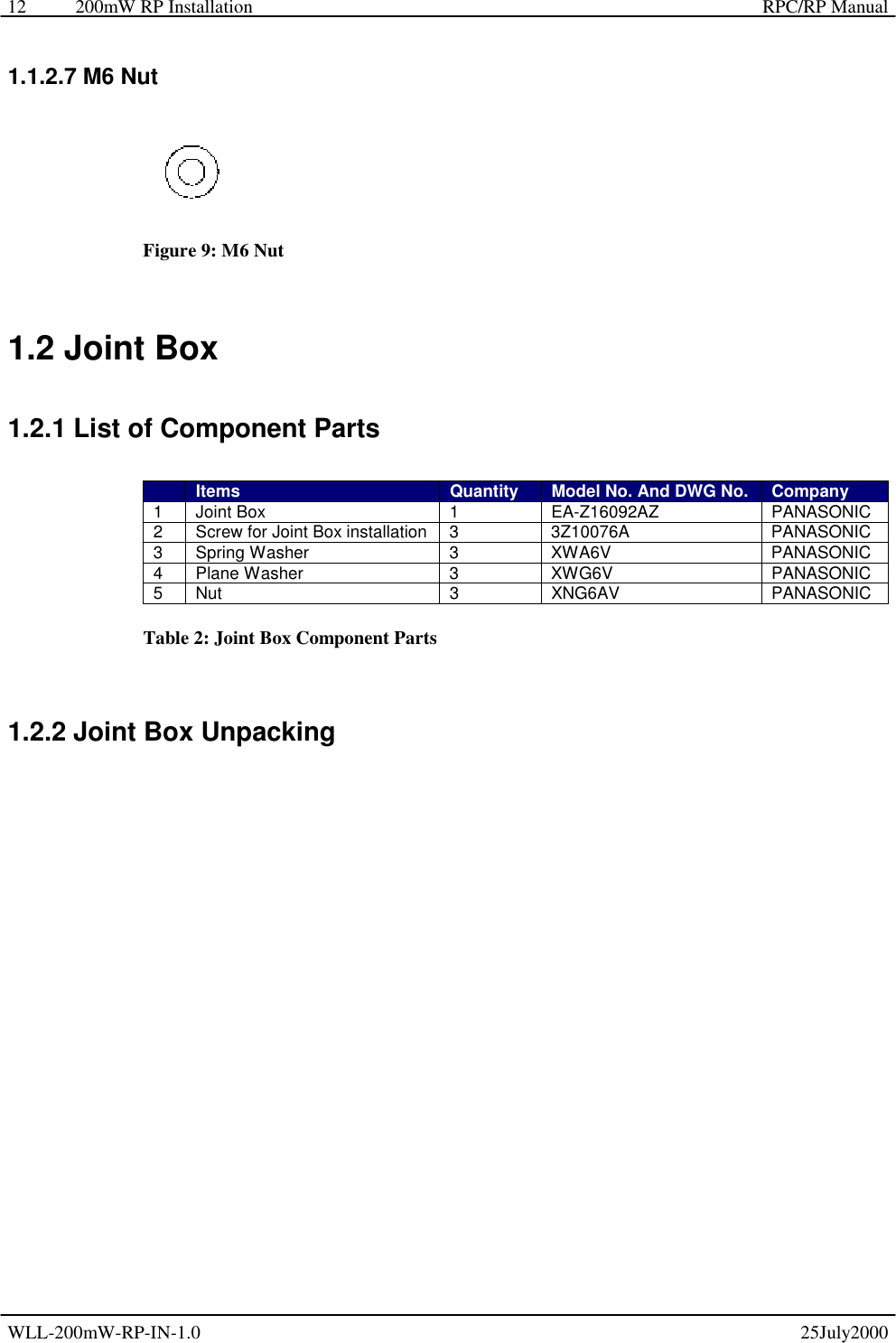
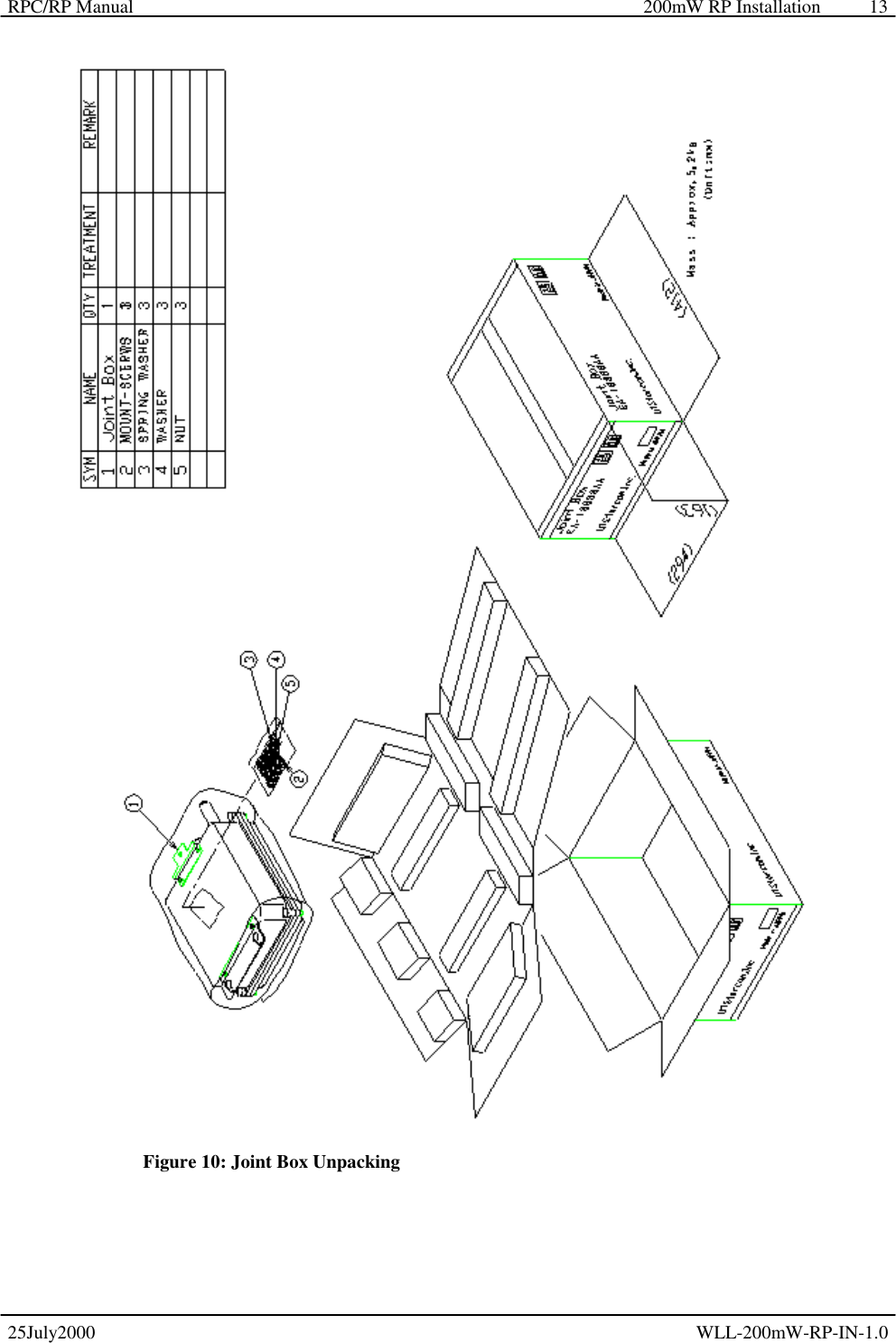
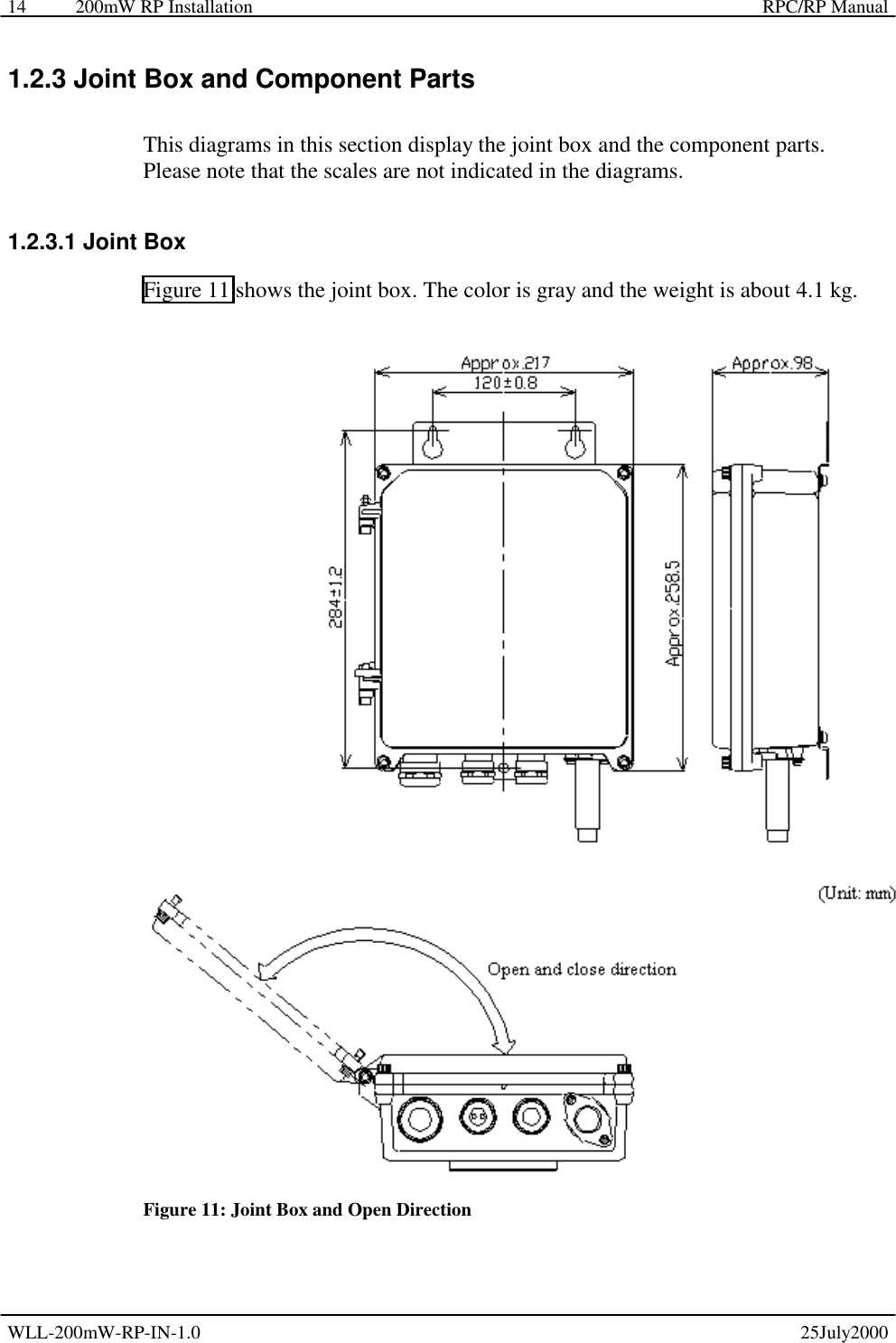
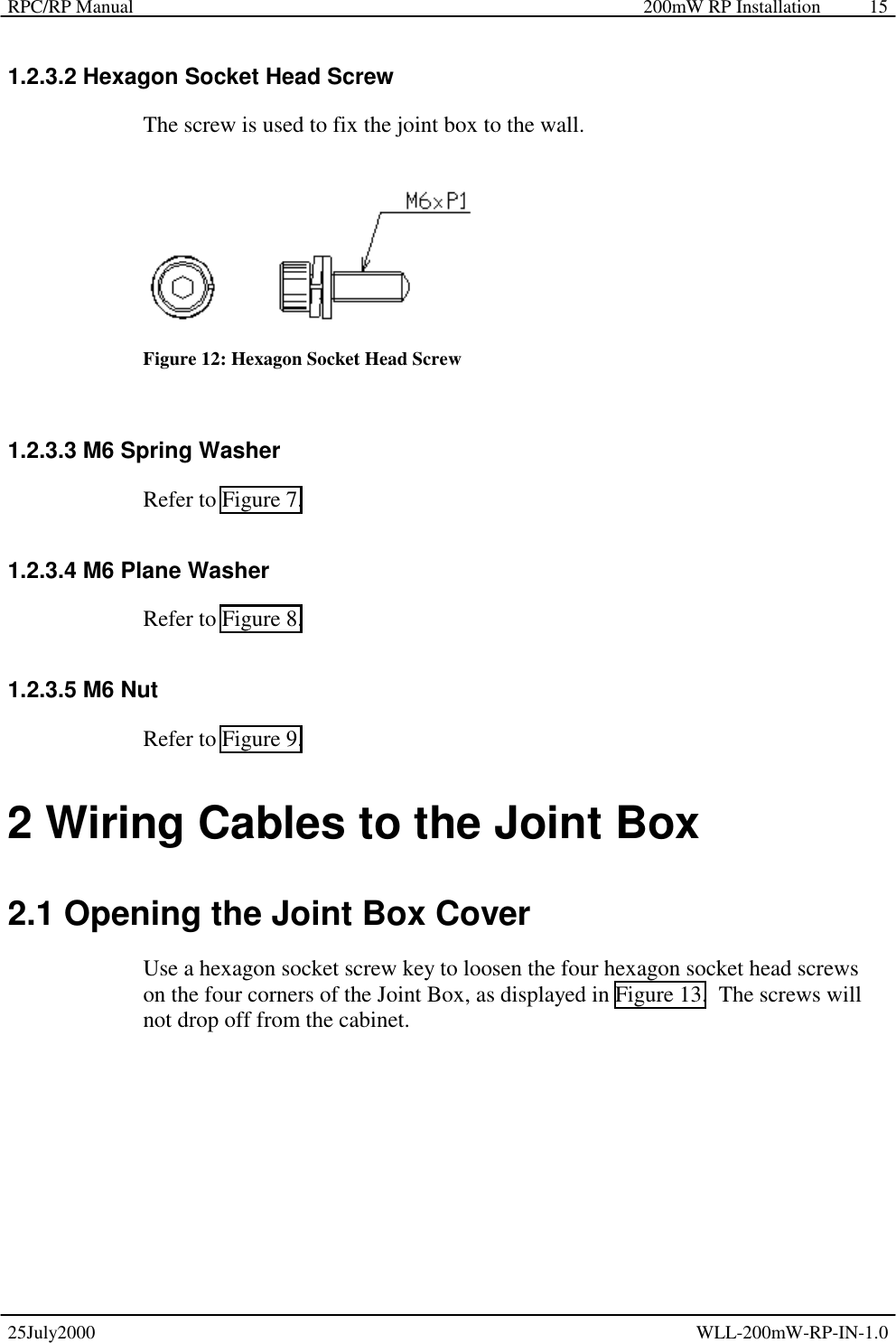
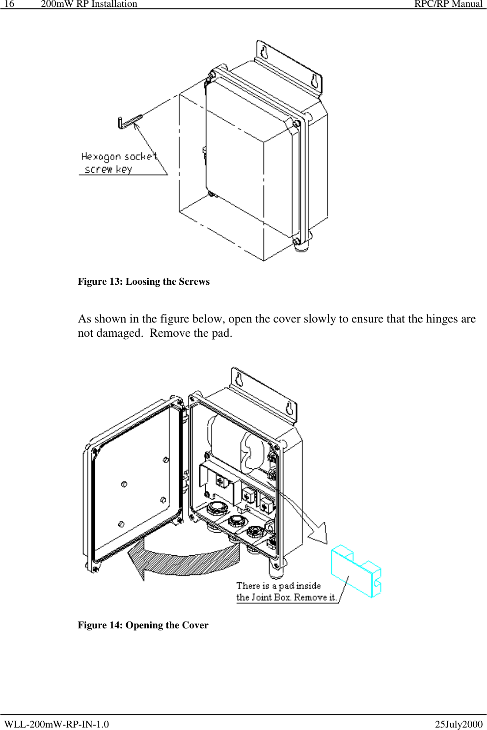
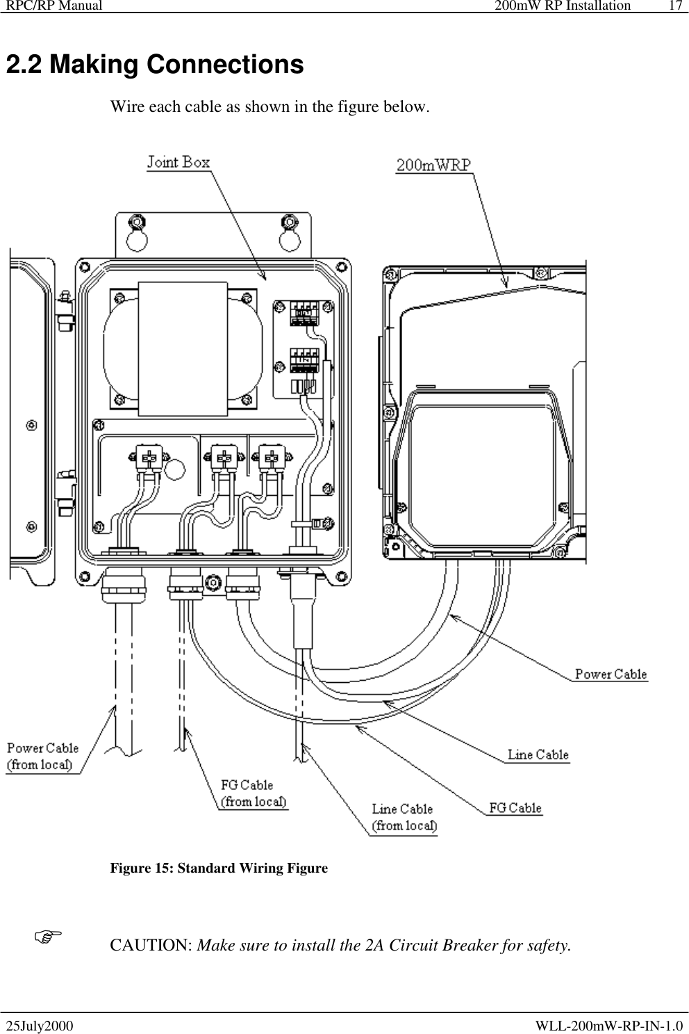
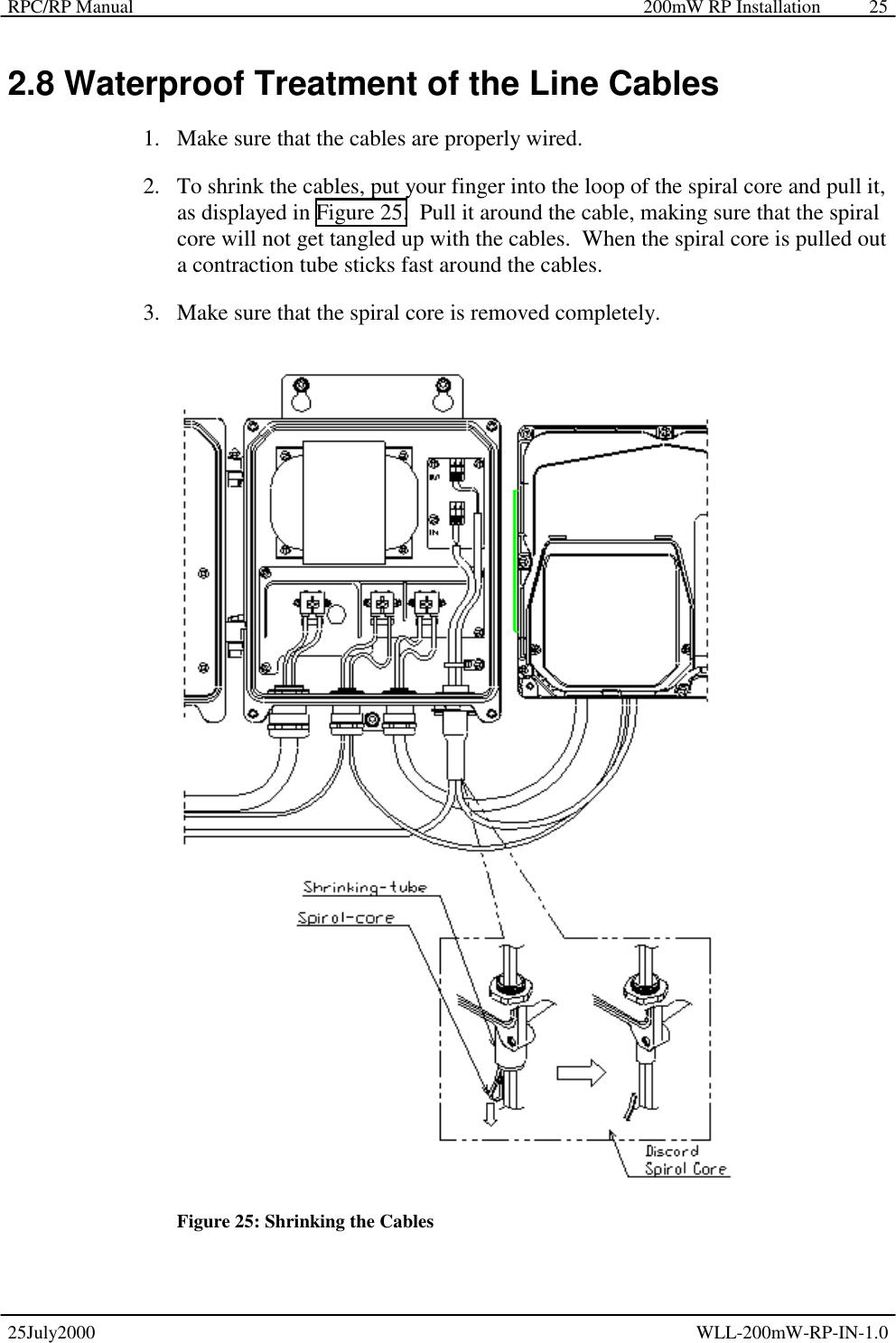
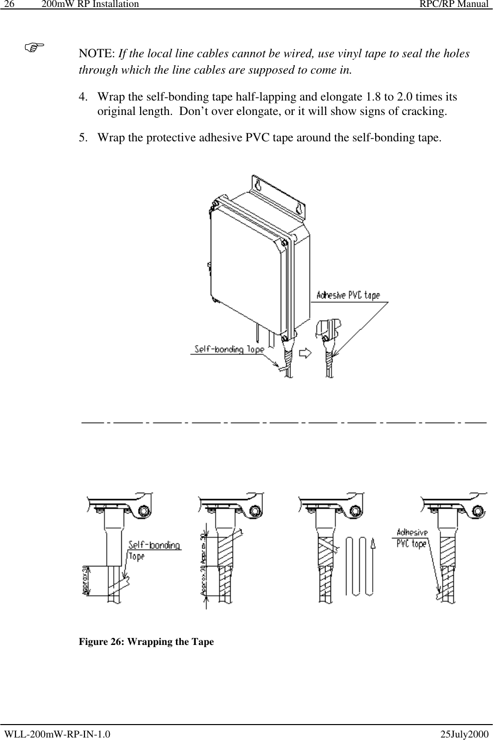
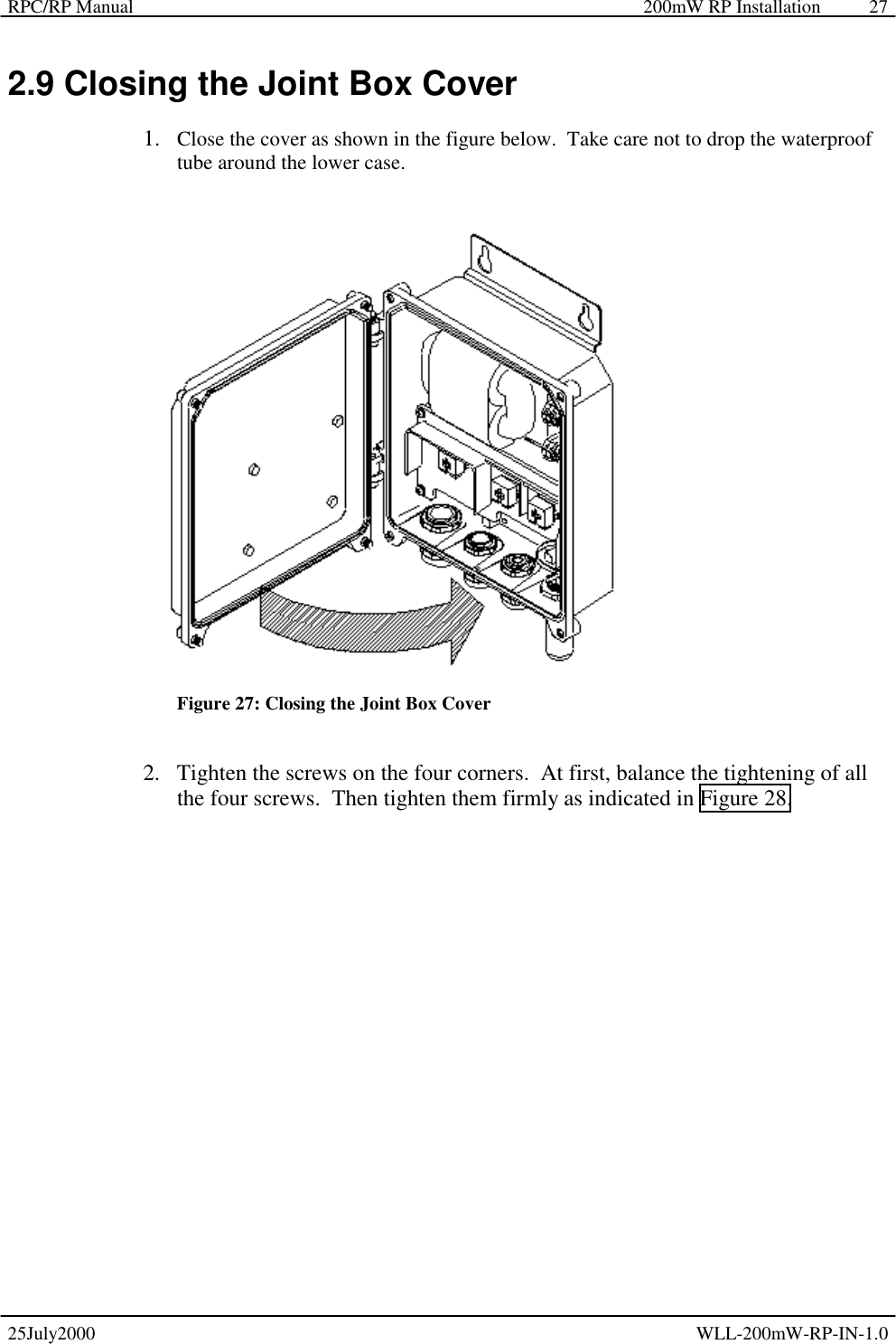
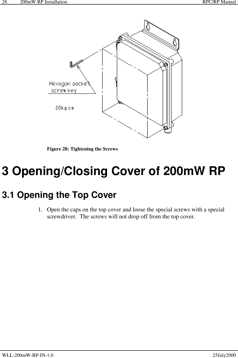
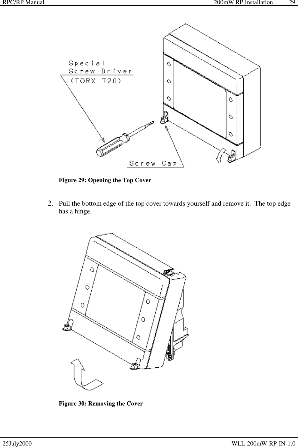
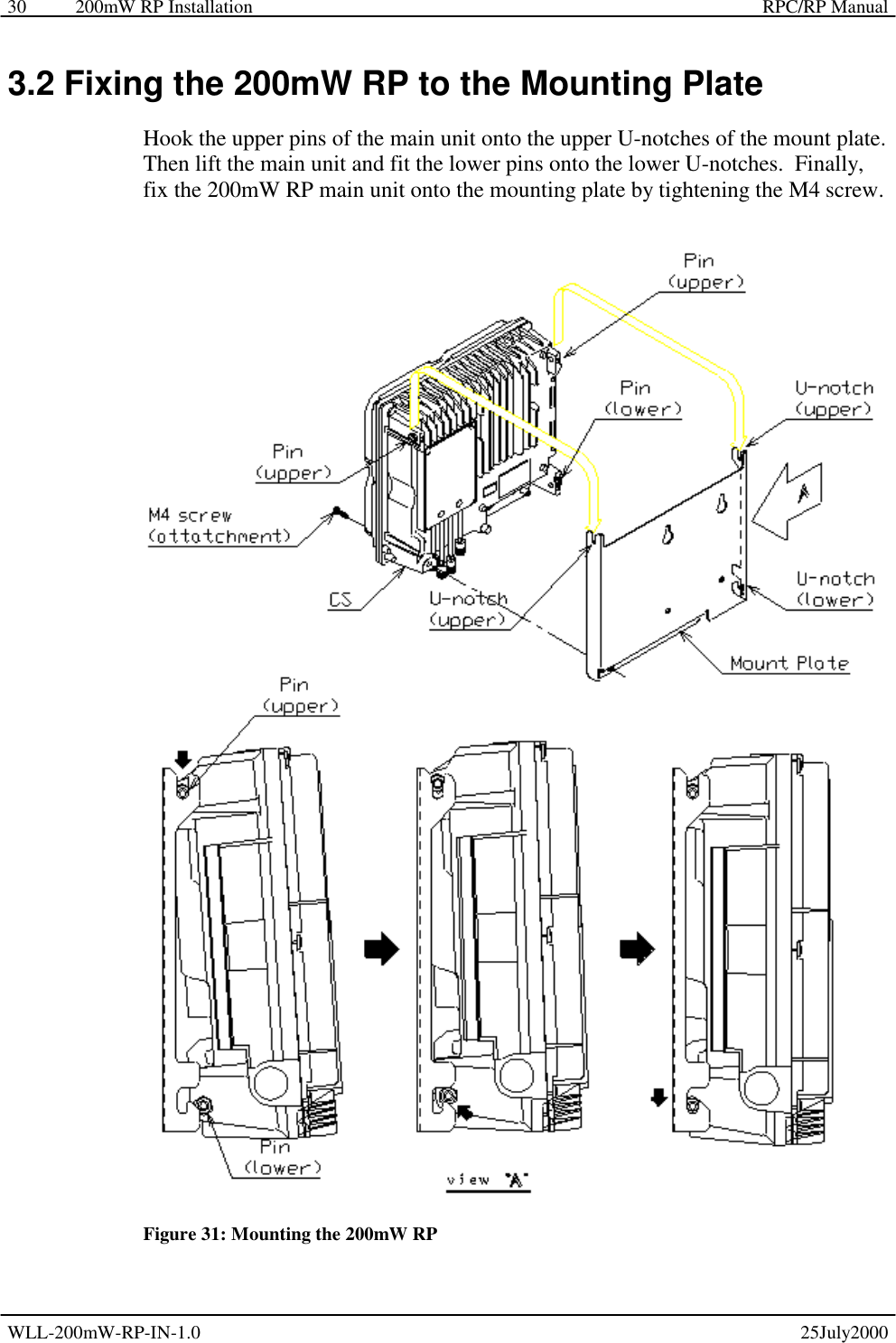
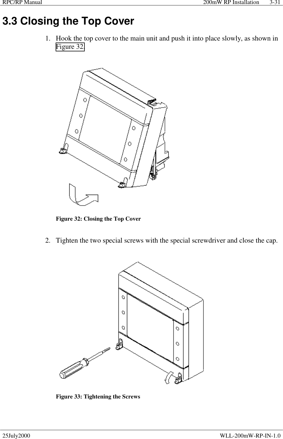
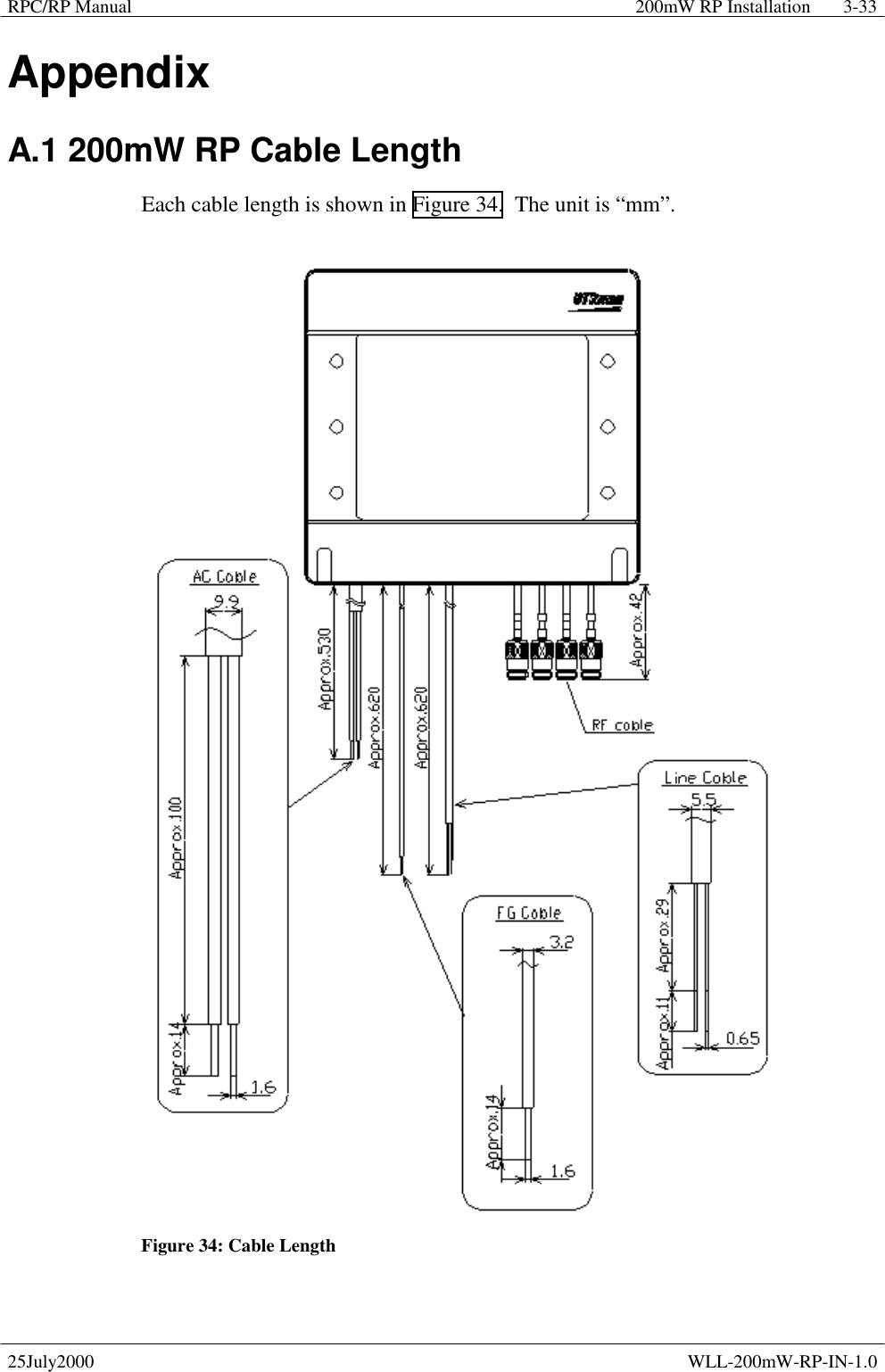
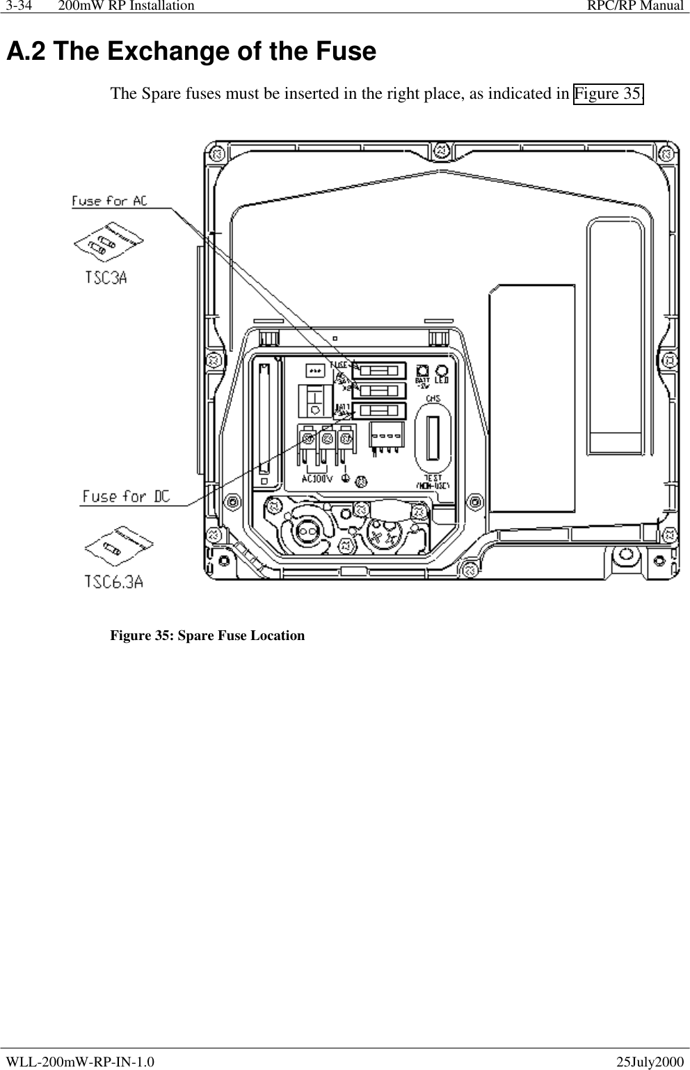
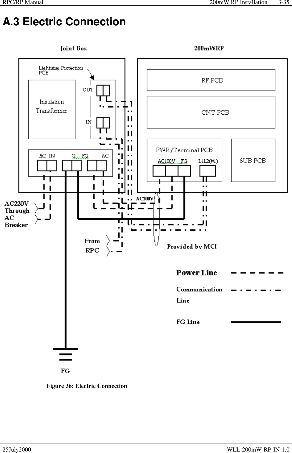
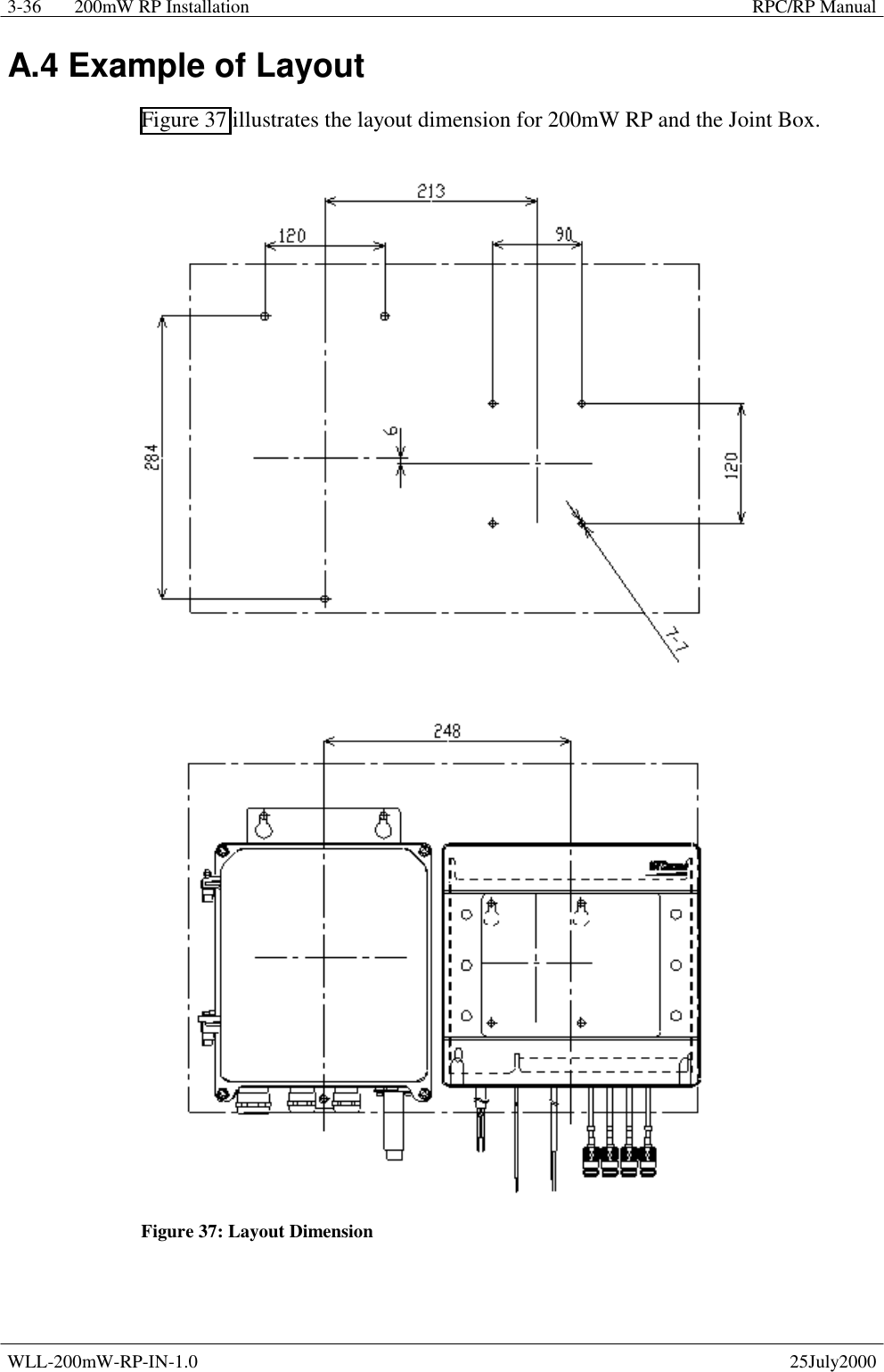
Install Manual