UTStarcom Korea Technologies UTS-EA7T56B Wireless Local Loop Phone System User Manual 2 General Description
UTStarcom Korea Technologies Ltd. Wireless Local Loop Phone System 2 General Description
Contents
- 1. Install Manual
- 2. Users Manual
Install Manual

200mW Radio Port
Installation Manual
WLL-200mW-RP-IN-1.0
July 25, 2000

200mW RP Installation RPC/RP Manual
WLL-200mW-RP-IN-1.0 25July2000
2
Compiled by (Joseph) Guangping Zhang
Copyright 2000 UTStarcom Inc. All Rights Reserved.
This manual has been prepared for UTStarcom customers, UTStarcom personnel,
and licensees. The information contained herein is the property of UTStarcom
Inc. and shall be neither reproduced nor utilized in any form or by any means,
electronically or mechanically, in whole or in part, without prior written approval
from UTStarcom Inc.

RPC/RP Manual 200mW RP Installation
25July2000 WLL-200mW-RP-IN-1.0
3
Important Safety Instructions !
• The sign on the top right corner is intended to alert the user the presence of important
operation and maintenance (service) instructions in the literature accompanying the product.
Also notice warnings such as “WARNING!” or “CAUTION.”
• When installing, operating, or maintaining the system, please follow the basic safety
procedures in order to reduce the risk of fire, electric shock, and injury to persons, as listed
below:
• Read and understand all instructions.
• Follow all warnings and instructions marked on this product.
• For information on proper mounting instructions, consult the Installation Manual provided
with this product.
• Install only equipment identified in the Installation Manual provided with this product. Use
of other equipment may result in improper connection of circuitry leading to fire or injury to
persons.
• The telecommunication interfaces should not leave the building unless connected to
telecommunication devices providing primary and secondary protection, as applicable.
• This product should only be operated from the type of power source indicated on the marking
label.
• This equipment must be provided with a readily accessible disconnect device as part of the
building installation.
• Installation must include an independent frame ground drop to building ground. Refer to
installation instructions.
• Do not use this product near water, for example in a wet basement.
• Do not place this product on an unstable cart, stand, or table. The product may fall, causing
serious damage to the product.

200mW RP Installation RPC/RP Manual
WLL-200mW-RP-IN-1.0 25July2000
4
• Use caution when installing or modifying telecommunications lines.
• Never install telecommunications wiring during a lightning storm.
• Never install telecommunications in wet locations.
• Never touch uninsulated telecommunications wires or terminals unless the
telecommunications line has been disconnected at the network interface.
• Never touch uninsulated telecommunications wires or terminals carrying direct current or
ringing current or leave this wiring exposed. Protect and tape such wiring and terminals to
avoid risk of fire, electric shock, and injury to service personnel.
• Never push objects of any kind into this product through slots as they may touch dangerous
voltage points or short-out parts that could result in a risk of fire or electrical shock. Never
spill liquids of any kind on this product.
• Slots and openings in the unit are provided for ventilation, to protect it from overheating.
These openings must not be blocked or covered. This product should not be placed in a
built-in installation unless proper ventilation is provided.
• To reduce the risk of an electrical shock, do not disassemble this product. Service should be
performed by trained personnel only. Opening or removing covers and/or circuit boards may
expose you to dangerous voltages or other risks. Incorrect re-assembly can cause electrical
shock when the unit is subsequently used.
• This equipment is intended for installation in restricted access locations where access is
controlled or where access can only be gained by service personnel with a key or tool.
Access to this equipment is restricted to qualified service personnel.
Save These Instructions!

RPC/RP Manual 200mW RP Installation
25July2000 WLL-200mW-RP-IN-1.0
5
Table of Contents
1 Equipment Description...............................................................................................................................................6
1.1 200mW RP ..........................................................................................................................................................6
1.1.1 List of Component Parts...............................................................................................................................6
1.1.2 Appearance of 200mW RP and Component Parts........................................................................................8
1.1.2.1 200mW RP ............................................................................................................................................8
1.1.2.2 Mounting Plate.................................................................................................................................10
1.1.2.3 M4 Screw.............................................................................................................................................10
1.1.2.4 M6 Screw.............................................................................................................................................11
1.1.2.5 M6 Spring Washer...............................................................................................................................11
1.1.2.6 M6 Plane Washer.................................................................................................................................11
1.1.2.7 M6 Nut.................................................................................................................................................12
1.2 Joint Box............................................................................................................................................................12
1.2.1 List of Component Parts.............................................................................................................................12
1.2.2 Joint Box Unpacking ..................................................................................................................................12
1.2.3 Joint Box and Component Parts .................................................................................................................14
1.2.3.1 Joint Box..............................................................................................................................................14
1.2.3.2 Hexagon Socket Head Screw...............................................................................................................15
1.2.3.3 M6 Spring Washer...............................................................................................................................15
1.2.3.4 M6 Plane Washer.................................................................................................................................15
1.2.3.5 M6 Nut.................................................................................................................................................15
2 Wiring Cables to the Joint Box.................................................................................................................................15
2.1 Opening the Joint Box Cover ............................................................................................................................15
2.2 Making Connections..........................................................................................................................................17
2.3 Names of the Connection Joints ........................................................................................................................18
2.4 Connecting the AC Power Cables and FG Cables.............................................................................................19
2.5 Connecting the Line Cables...............................................................................................................................21
2.6 Fixing the AC Power Cables and FG Cables.....................................................................................................22
2.7 Fixing the Line Cables.......................................................................................................................................24
2.8 Waterproof Treatment of the Line Cables.........................................................................................................25
2.9 Closing the Joint Box Cover..............................................................................................................................27
3 Opening/Closing Cover of 200mW RP....................................................................................................................28
3.1 Opening the Top Cover .....................................................................................................................................28
3.2 Fixing the 200mW RP to the Mounting Plate....................................................................................................30
3.3 Closing the Top Cover................................................................................................................................... 3-31
Appendix ................................................................................................................................................................. 3-33
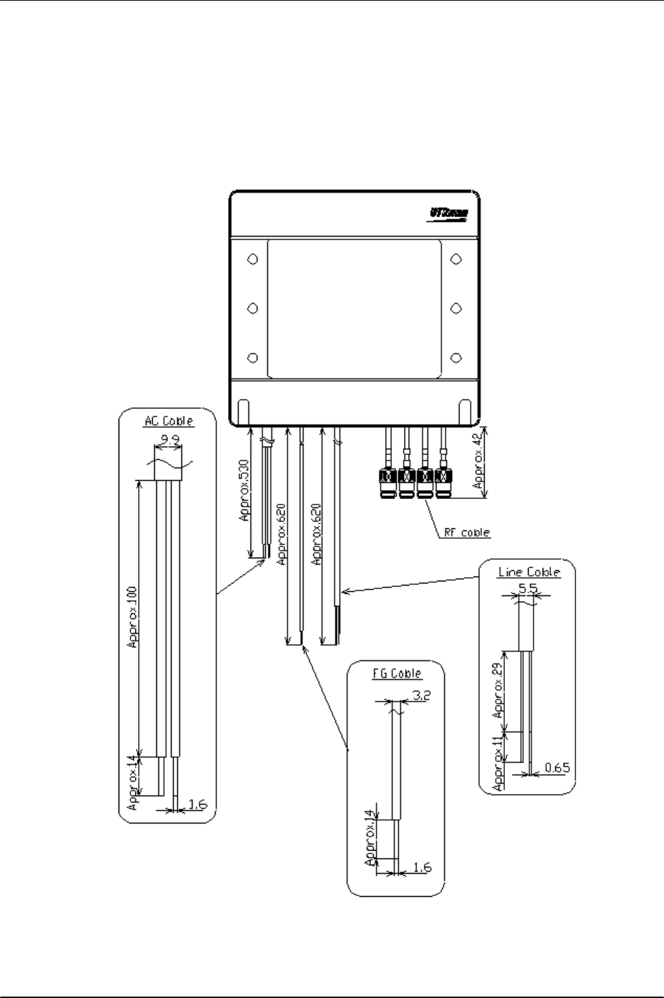
A.1 200mW RP Cable Length............................................................................................................................. 3-33
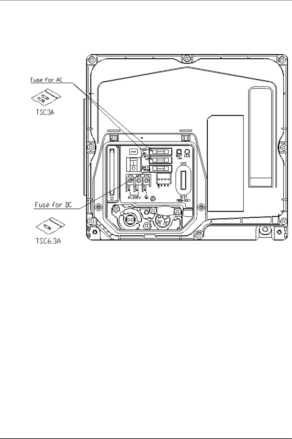
A.2 The Exchange of the Fuse............................................................................................................................. 3-34
A.3 Electric Connection ...................................................................................................................................... 3-35
A.4 Example of Layout ....................................................................................................................................... 3-36
A.5 Suitable Size of the Local Cable................................................................................................................... 3-37
A.6 Tape Wrapping ............................................................................................................................................. 3-38
A.7 Water Proof of Antenna Cable...................................................................................................................... 3-39
A.8 Grounding Protective Earthing Cable........................................................................................................... 3-40
A.9 Installation Image ......................................................................................................................................... 3-42

200mW RP Installation RPC/RP Manual
WLL-200mW-RP-IN-1.0 25July2000
6
1 Equipment Description
This chapter describes all the components involved in the 200mW RP installation,
including the 200mW RP and the joint box.
1.1 200mW RP
This section represents the 200mW RP installation.
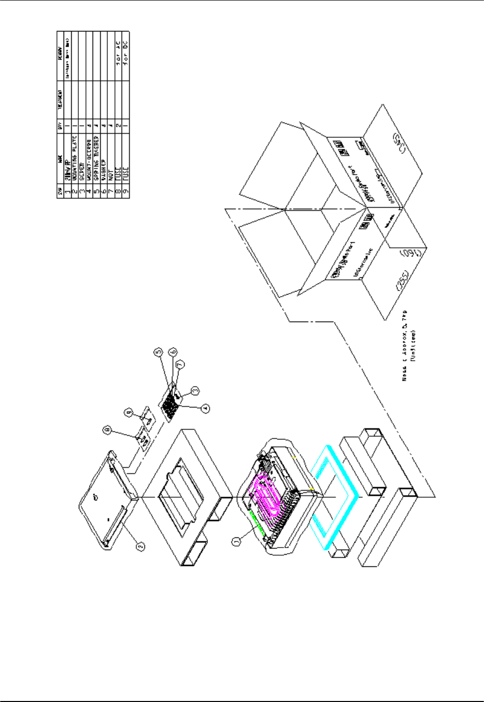
1.1.1 List of Component Parts
Items Quantity Model No. and DWG No. Company
1 200mWRP Main Unit 1 EA-7T56 PANASONIC
2 Screw for CS installation 1 XYN4•F18V PANASONIC
3 Mounting Plate 1 1B14449C PANASONIC
4 Screw for Mounting Plate 4 3Z10076A PANASONIC
5 Spring Washer 4 XWA6V PANASONIC
6 Plane Washer 4 XWG6V PANASONIC
7 Nut 4 XNG6AV PANASONIC
8 Spare Fuse 2 TSC3A PANASONIC
9 Spare Fuse 1 TSC6.3A PANASONIC
Table 1: Component Parts
! NOTE: No. 8 and No. 9 are spare fuses. The spare fuse must be inserted in the
right place.
RPC/RP Manual 200mW RP Installation
25July2000 WLL-200mW-RP-IN-1.0
7
Figure 1: 200mW RP Unpacking
200mW RP Installation RPC/RP Manual
WLL-200mW-RP-IN-1.0 25July2000
8
1.1.2 Appearance of 200mW RP and Component Parts
This section displays the main unit of the 200mW RP and the mounting parts.
Scales are not indicated in the diagrams.
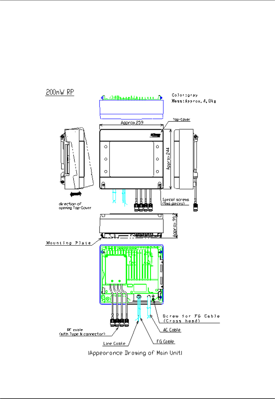
1.1.2.1 200mW RP
Figure 2: 200mW RP Main Unit
RPC/RP Manual 200mW RP Installation
25July2000 WLL-200mW-RP-IN-1.0
9
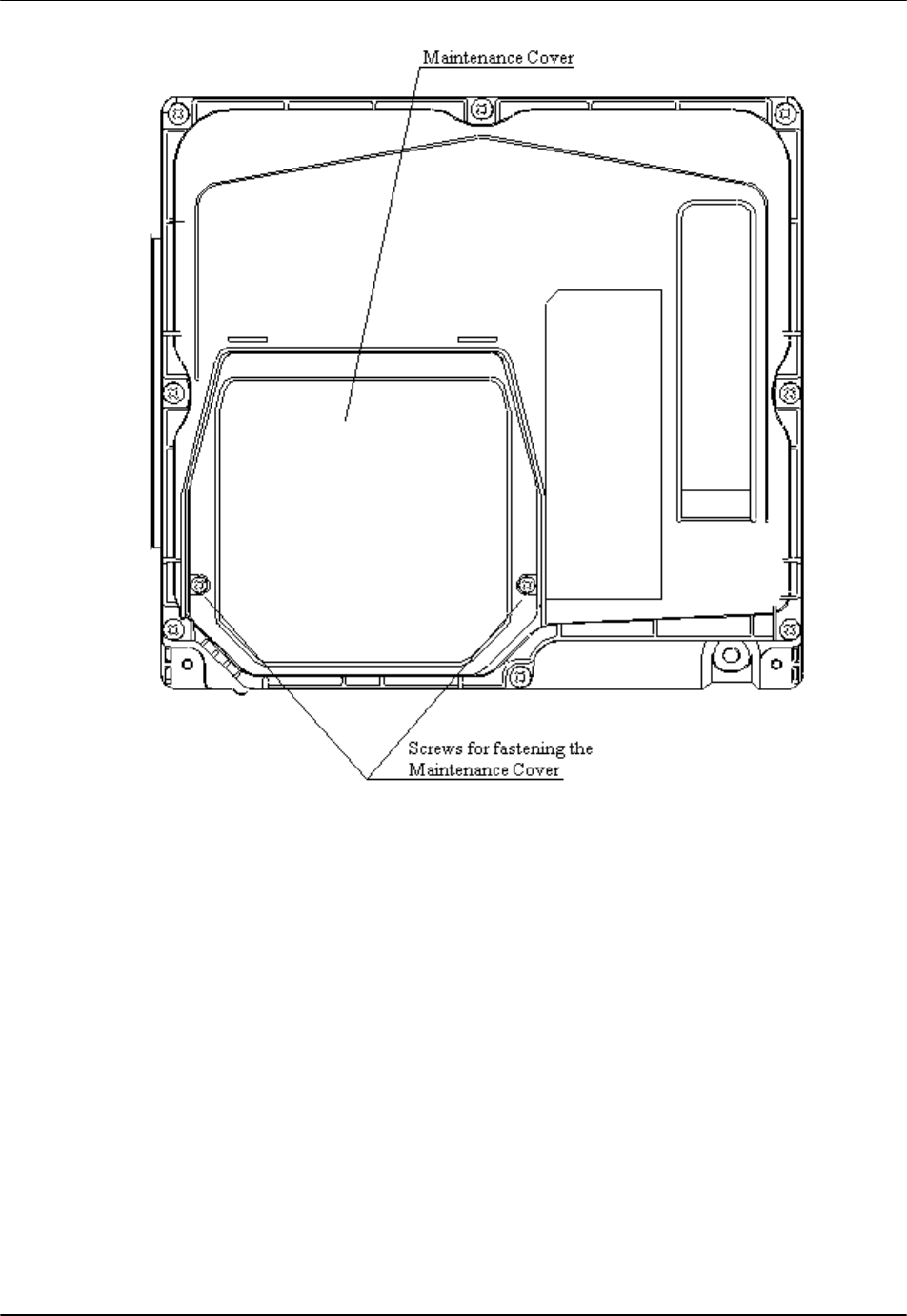
Figure 3: Front View of the Main Unit (without the Top Cover)
200mW RP Installation RPC/RP Manual
WLL-200mW-RP-IN-1.0 25July2000
10
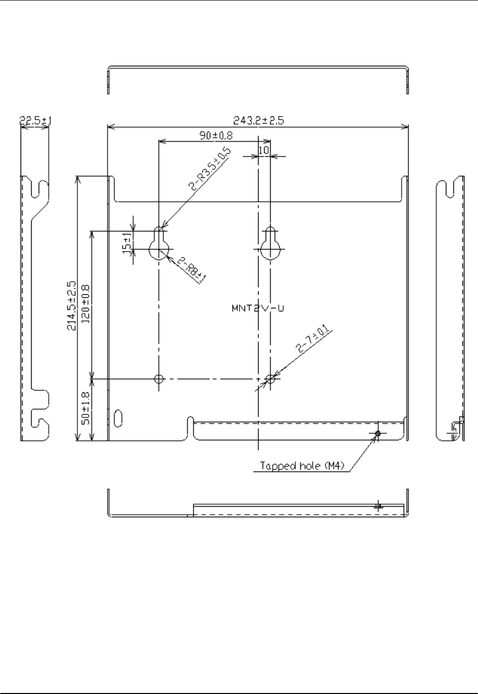
1.1.2.2 Mounting Plate
Figure 4: 200mW RP Mounting Plate (RP Mounting Base)
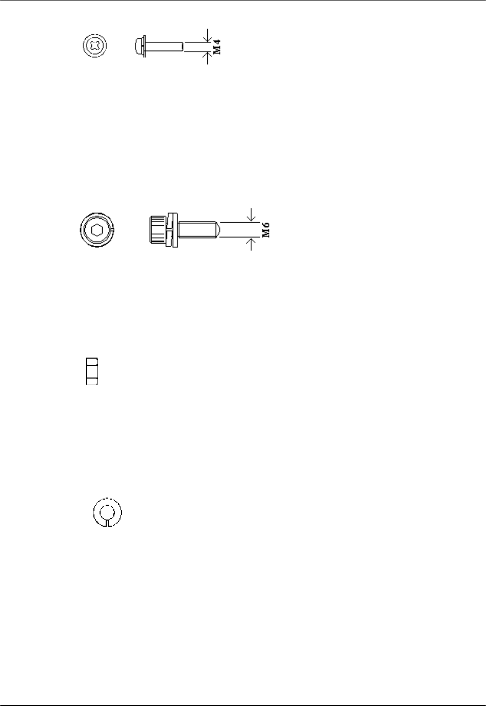
1.1.2.3 M4 Screw
The M4 screw is used to fix the RP onto the Mounting Plate
RPC/RP Manual 200mW RP Installation
25July2000 WLL-200mW-RP-IN-1.0
11
Figure 5: M4 Screw and Its Cross Head
1.1.2.4 M6 Screw
The M6 screw is used to mount the Mounting Plate onto the wall.
Figure 6: M6 Screw and Its Socket Head
1.1.2.5 M6 Spring Washer
Figure 7: M6 Spring Washer
1.1.2.6 M6 Plane Washer
Figure 8: M6 Plane Washer

200mW RP Installation RPC/RP Manual
WLL-200mW-RP-IN-1.0 25July2000
12
1.1.2.7 M6 Nut
Figure 9: M6 Nut
1.2 Joint Box
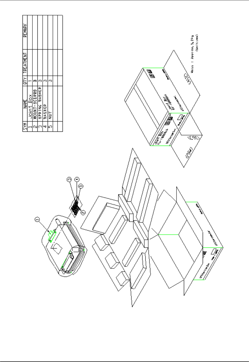
1.2.1 List of Component Parts
Items Quantity Model No. And DWG No. Company
1 Joint Box 1 EA-Z16092AZ PANASONIC
2 Screw for Joint Box installation 3 3Z10076A PANASONIC
3 Spring Washer 3 XWA6V PANASONIC
4 Plane Washer 3 XWG6V PANASONIC
5 Nut 3 XNG6AV PANASONIC
Table 2: Joint Box Component Parts
1.2.2 Joint Box Unpacking
RPC/RP Manual 200mW RP Installation
25July2000 WLL-200mW-RP-IN-1.0
13
Figure 10: Joint Box Unpacking
200mW RP Installation RPC/RP Manual
WLL-200mW-RP-IN-1.0 25July2000
14
1.2.3 Joint Box and Component Parts
This diagrams in this section display the joint box and the component parts.
Please note that the scales are not indicated in the diagrams.
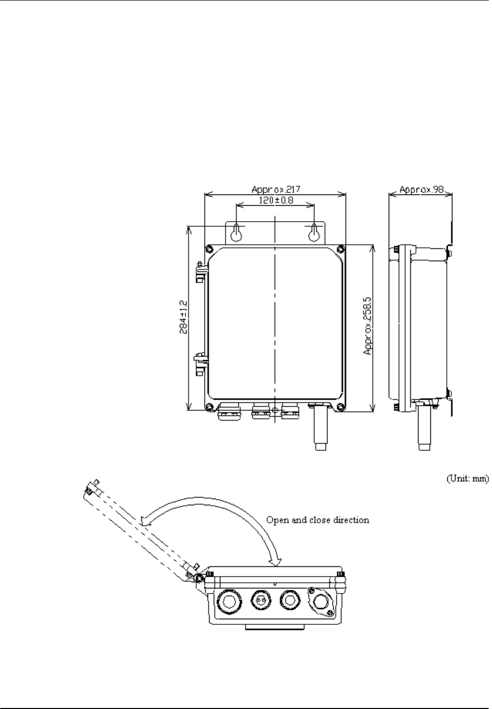
1.2.3.1 Joint Box
Figure 11 shows the joint box. The color is gray and the weight is about 4.1 kg.
Figure 11: Joint Box and Open Direction

RPC/RP Manual 200mW RP Installation
25July2000 WLL-200mW-RP-IN-1.0
15
1.2.3.2 Hexagon Socket Head Screw
The screw is used to fix the joint box to the wall.
Figure 12: Hexagon Socket Head Screw
1.2.3.3 M6 Spring Washer
Refer to Figure 7.
1.2.3.4 M6 Plane Washer
Refer to Figure 8.
1.2.3.5 M6 Nut
Refer to Figure 9.
2 Wiring Cables to the Joint Box
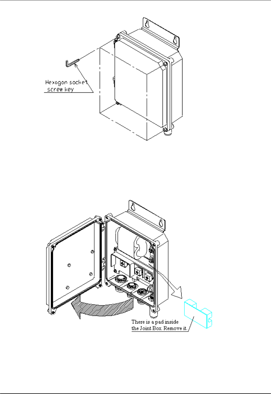
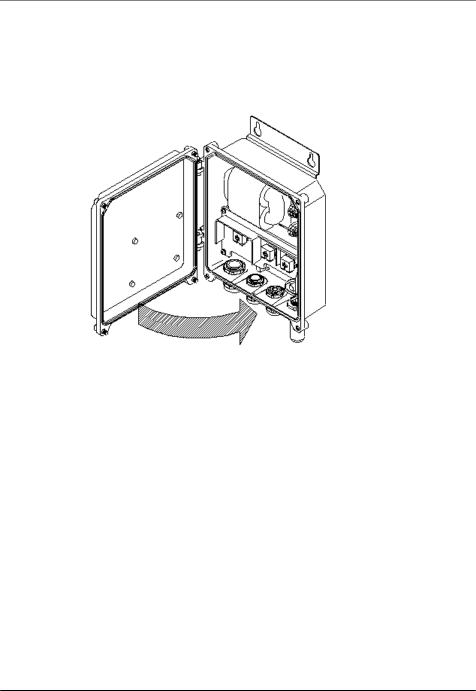
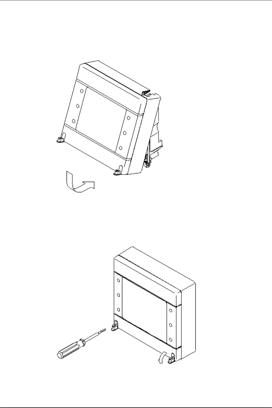
2.1 Opening the Joint Box Cover
Use a hexagon socket screw key to loosen the four hexagon socket head screws
on the four corners of the Joint Box, as displayed in Figure 13. The screws will
not drop off from the cabinet.
200mW RP Installation RPC/RP Manual
WLL-200mW-RP-IN-1.0 25July2000
16
Figure 13: Loosing the Screws
As shown in the figure below, open the cover slowly to ensure that the hinges are
not damaged. Remove the pad.
Figure 14: Opening the Cover
RPC/RP Manual 200mW RP Installation
25July2000 WLL-200mW-RP-IN-1.0
17
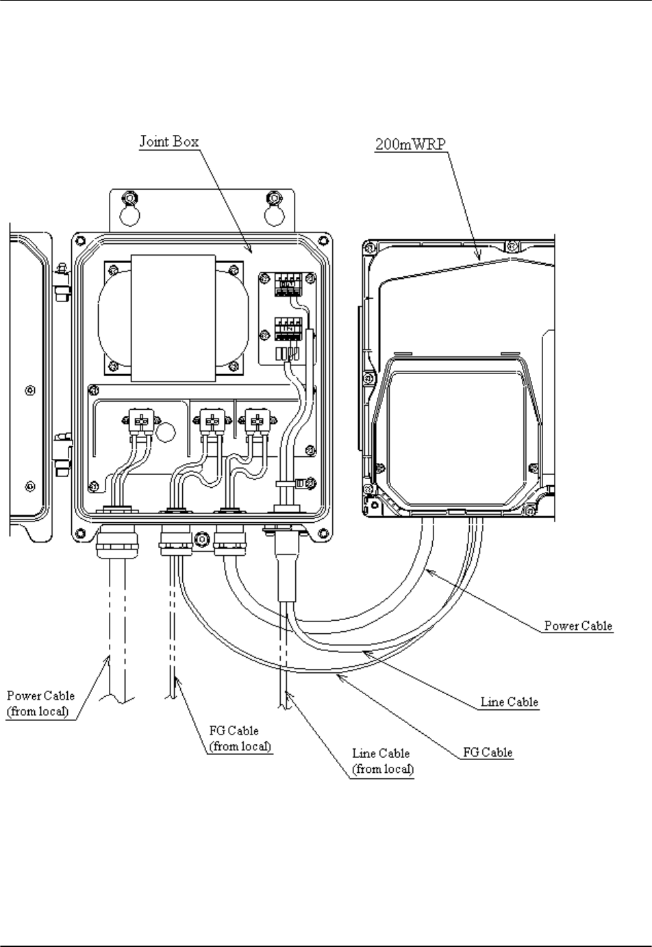
2.2 Making Connections
Wire each cable as shown in the figure below.
Figure 15: Standard Wiring Figure
! CAUTION: Make sure to install the 2A Circuit Breaker for safety.

200mW RP Installation RPC/RP Manual
WLL-200mW-RP-IN-1.0 25July2000
18
! WARNING:
• Keep Commercial Circuit Breakers OFF when installing or reinstalling
devices
• Connect the power source cables completely
• Do not drop hardware into the openings in the interface
• Do not work with wet hands
• Do not wet the inside of the devices when installing
• Ground the instrument properly (Improper grounding may cause an
electric shock)
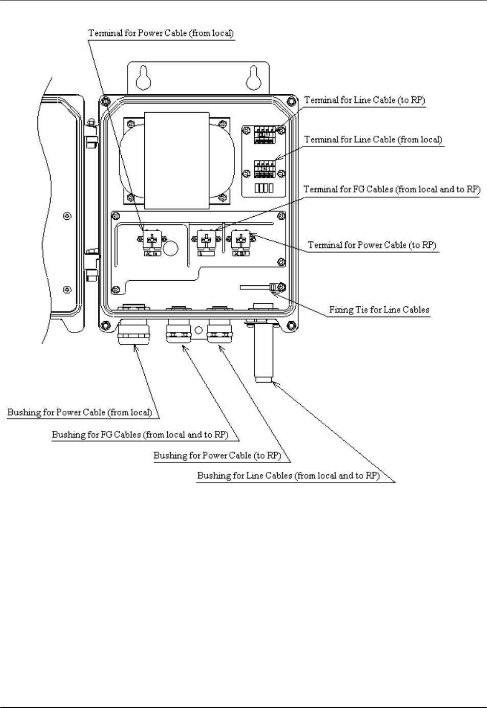
2.3 Names of the Connection Joints
RPC/RP Manual 200mW RP Installation
25July2000 WLL-200mW-RP-IN-1.0
19
Figure 16: Terminals on the Joint Box
2.4 Connecting the AC Power Cables and FG Cables
! CAUTION: The diameter of the cable connected to this terminal is
φ
1.2 to 2.0
mm for single wire.
1. Loosen bushings and put the Power and FG cables through each bushing.
200mW RP Installation RPC/RP Manual
WLL-200mW-RP-IN-1.0 25July2000
20
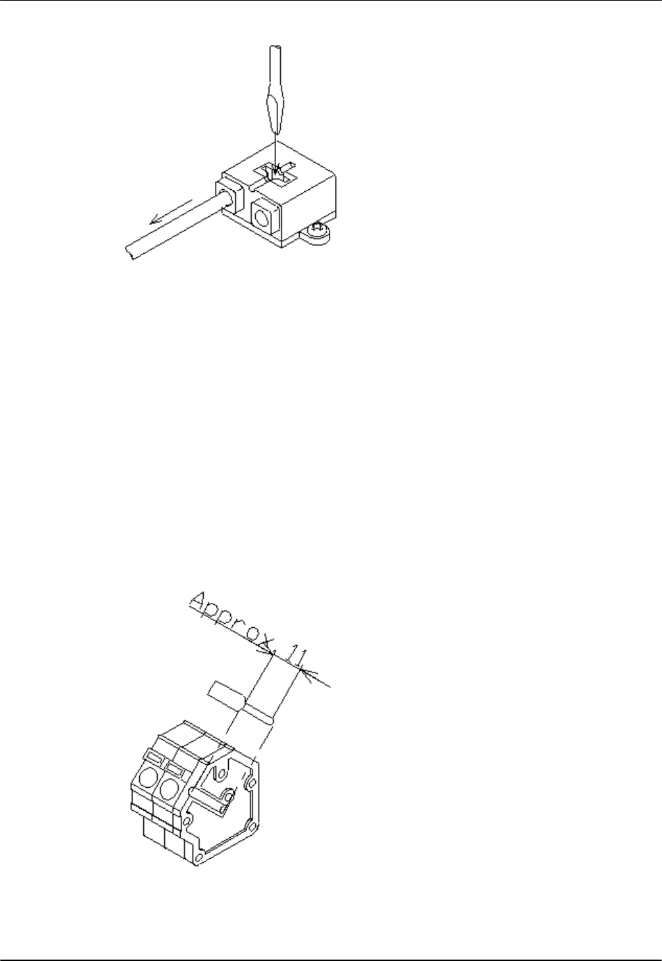
2. Peel off the cable coating to the length that corresponds to the strip gauge on
the terminal, as indicated in Figure 17.
Figure 17: Strip Gauge on the Terminal
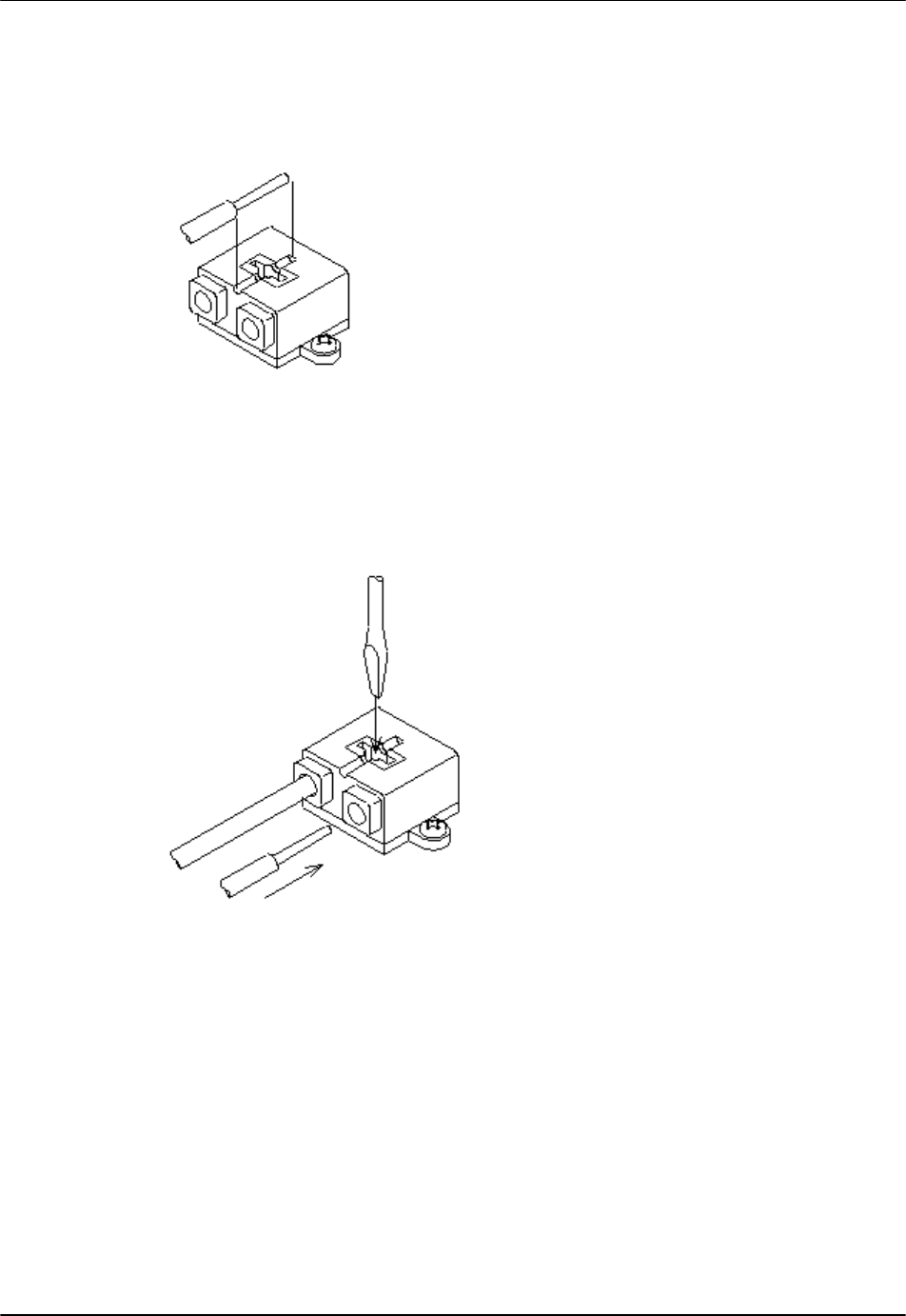
3. Insert the cables firmly until they come to the end.
Figure 18: Inserting the Cable
4. If the cable is connected wrongly, use a proper tool to press down the button
of the terminal and pull out the attached cable. Then insert it again. The
proper tools that can be used for the purpose include:
• Regular screwdriver (shaft diameter: 6, nose width: 6)
• Phillips screwdriver (shaft diameter: 4)
RPC/RP Manual 200mW RP Installation
25July2000 WLL-200mW-RP-IN-1.0
21
Figure 19: Tools for Disconnecting the Cable
2.5 Connecting the Line Cables
! CAUTION: The diameters of the cable connected to this terminal are
φ
0.4 to 1.6
mm for single wire and
φ
0.3 to 1.25 mm for twisted wire.
1. Put the Line cable through the bushing.
2. Peel off the cable coating to the length that corresponds to the strip gauge on
the terminal, as indicated in Figure 20.
Figure 20: Strip Gauge on the Terminal
200mW RP Installation RPC/RP Manual
WLL-200mW-RP-IN-1.0 25July2000
22
3. Insert the cables firmly until they come to the end.
Figure 21: Inserting the Cable
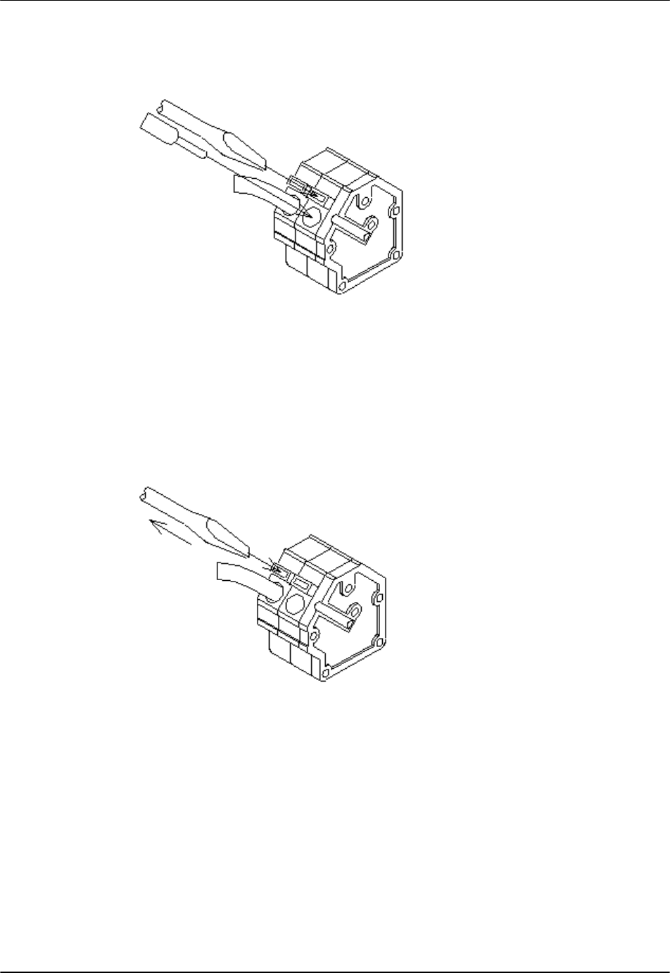
4. If the cable is connected wrongly, use a proper tool to press down the button
of the terminal and pull out the attached cable. Then insert it again. The
proper tool that can be used for the purpose is a regular screwdriver (shaft
diameter: 3, nose width: 2.6)
Figure 22: Tools for Disconnecting the Cable
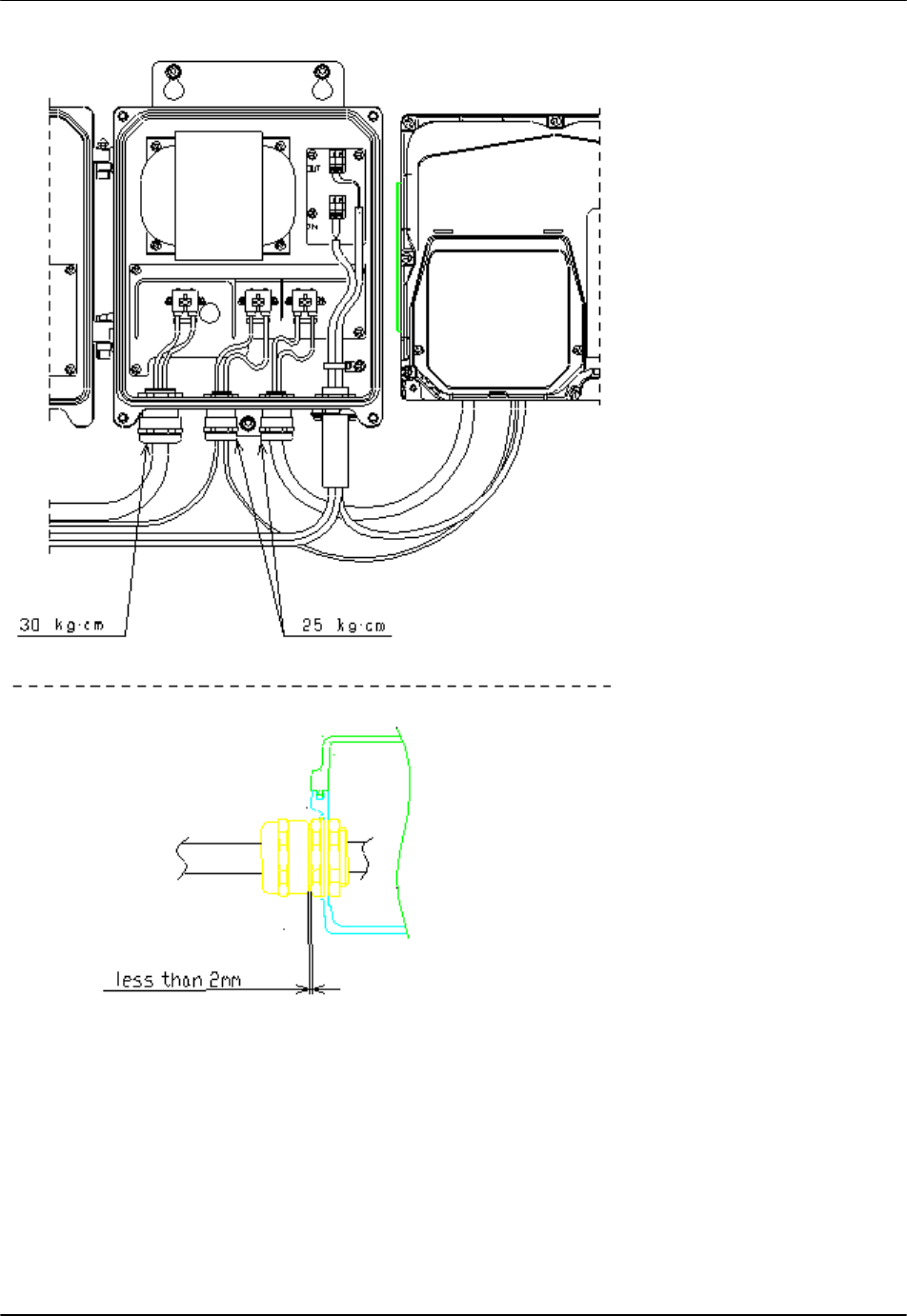
2.6 Fixing the AC Power Cables and FG Cables
Tighten the Power and FG cables' Bushings (3 places) firmly at the torque
indicated in Figure 23 or until the interval becomes less than 2mm.
RPC/RP Manual 200mW RP Installation
25July2000 WLL-200mW-RP-IN-1.0
23
Figure 23: Power and FG Cable Fixing
200mW RP Installation RPC/RP Manual
WLL-200mW-RP-IN-1.0 25July2000
24
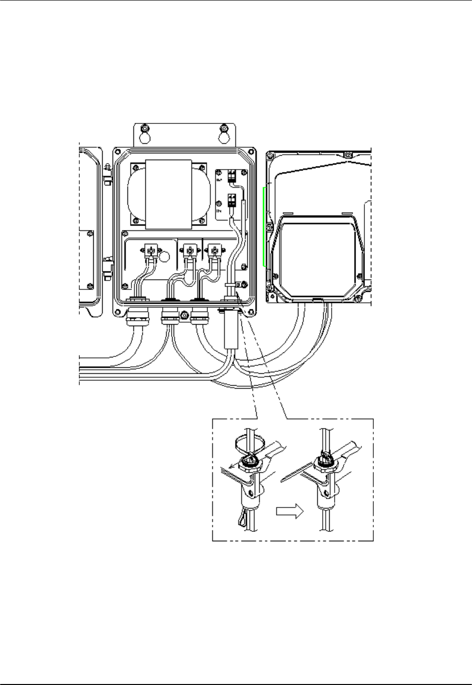
2.7 Fixing the Line Cables
As for the line cables, adjust their wiring margin as shown in Figure 24, and bundle and
fix them with Insulock Tie (tie band). Cut off the surplus length of Insulock Tie with
nipper, etc.
Figure 24: Line Cable Fixing
! NOTE: If the local line cables cannot be wired, use vinyl tape to seal the holes
through which the line cables are supposed to come in.
RPC/RP Manual 200mW RP Installation
25July2000 WLL-200mW-RP-IN-1.0
25
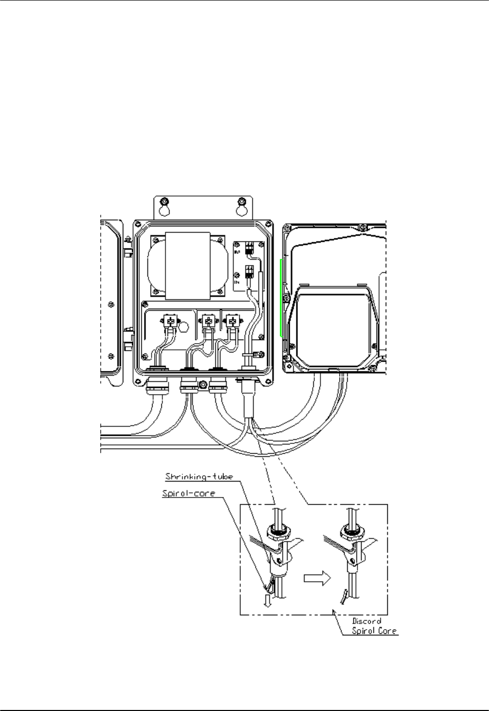
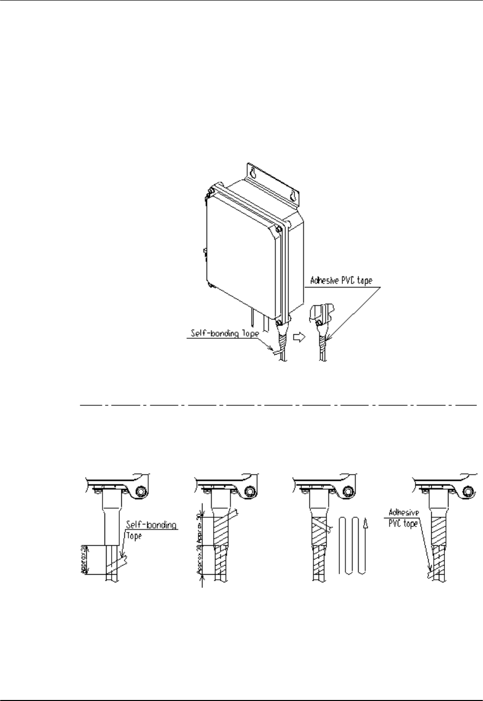
2.8 Waterproof Treatment of the Line Cables
1. Make sure that the cables are properly wired.
2. To shrink the cables, put your finger into the loop of the spiral core and pull it,
as displayed in Figure 25. Pull it around the cable, making sure that the spiral
core will not get tangled up with the cables. When the spiral core is pulled out
a contraction tube sticks fast around the cables.
3. Make sure that the spiral core is removed completely.
Figure 25: Shrinking the Cables
200mW RP Installation RPC/RP Manual
WLL-200mW-RP-IN-1.0 25July2000
26
! NOTE: If the local line cables cannot be wired, use vinyl tape to seal the holes
through which the line cables are supposed to come in.
4. Wrap the self-bonding tape half-lapping and elongate 1.8 to 2.0 times its
original length. Don’t over elongate, or it will show signs of cracking.
5. Wrap the protective adhesive PVC tape around the self-bonding tape.
Figure 26: Wrapping the Tape
RPC/RP Manual 200mW RP Installation
25July2000 WLL-200mW-RP-IN-1.0
27
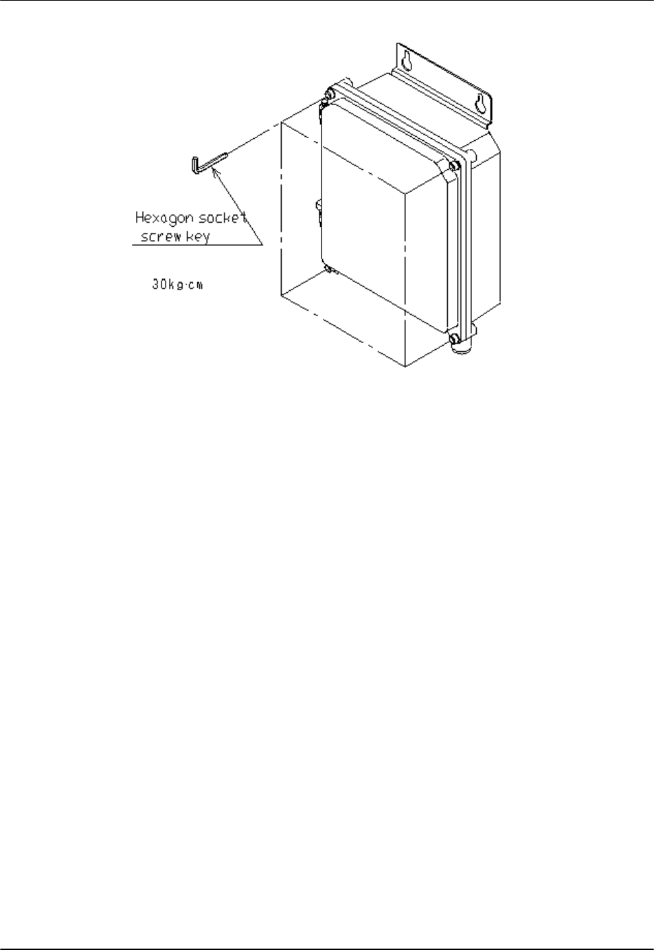
2.9 Closing the Joint Box Cover
1. Close the cover as shown in the figure below. Take care not to drop the waterproof
tube around the lower case.
Figure 27: Closing the Joint Box Cover
2. Tighten the screws on the four corners. At first, balance the tightening of all
the four screws. Then tighten them firmly as indicated in Figure 28.
200mW RP Installation RPC/RP Manual
WLL-200mW-RP-IN-1.0 25July2000
28
Figure 28: Tightening the Screws
3 Opening/Closing Cover of 200mW RP
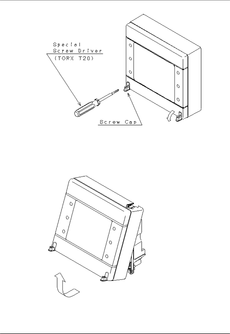
3.1 Opening the Top Cover
1. Open the caps on the top cover and loose the special screws with a special
screwdriver. The screws will not drop off from the top cover.
RPC/RP Manual 200mW RP Installation
25July2000 WLL-200mW-RP-IN-1.0
29
Figure 29: Opening the Top Cover
2. Pull the bottom edge of the top cover towards yourself and remove it. The top edge
has a hinge.
Figure 30: Removing the Cover
200mW RP Installation RPC/RP Manual
WLL-200mW-RP-IN-1.0 25July2000
30
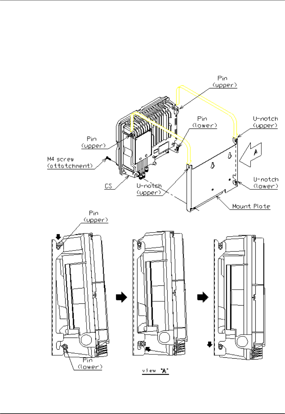
3.2 Fixing the 200mW RP to the Mounting Plate
Hook the upper pins of the main unit onto the upper U-notches of the mount plate.
Then lift the main unit and fit the lower pins onto the lower U-notches. Finally,
fix the 200mW RP main unit onto the mounting plate by tightening the M4 screw.
Figure 31: Mounting the 200mW RP
RPC/RP Manual 200mW RP Installation
25July2000 WLL-200mW-RP-IN-1.0
3-31
3.3 Closing the Top Cover
1. Hook the top cover to the main unit and push it into place slowly, as shown in
Figure 32.
Figure 32: Closing the Top Cover
2. Tighten the two special screws with the special screwdriver and close the cap.
Figure 33: Tightening the Screws

200mW RP Installation RPC/RP Manual
WLL-200mW-RP-IN-1.0 25July2000
3-32
! NOTE: Do not use an electric screwdriver to fasten the screws. Fasten the
screws with 12 kg.cm – 15 kg.com torque.
RPC/RP Manual 200mW RP Installation
25July2000 WLL-200mW-RP-IN-1.0
3-35
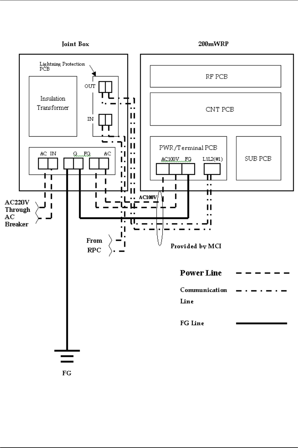
A.3 Electric Connection
Figure 36: Electric Connection
RPC/RP Manual 200mW RP Installation
25July2000 WLL-200mW-RP-IN-1.0
3-37
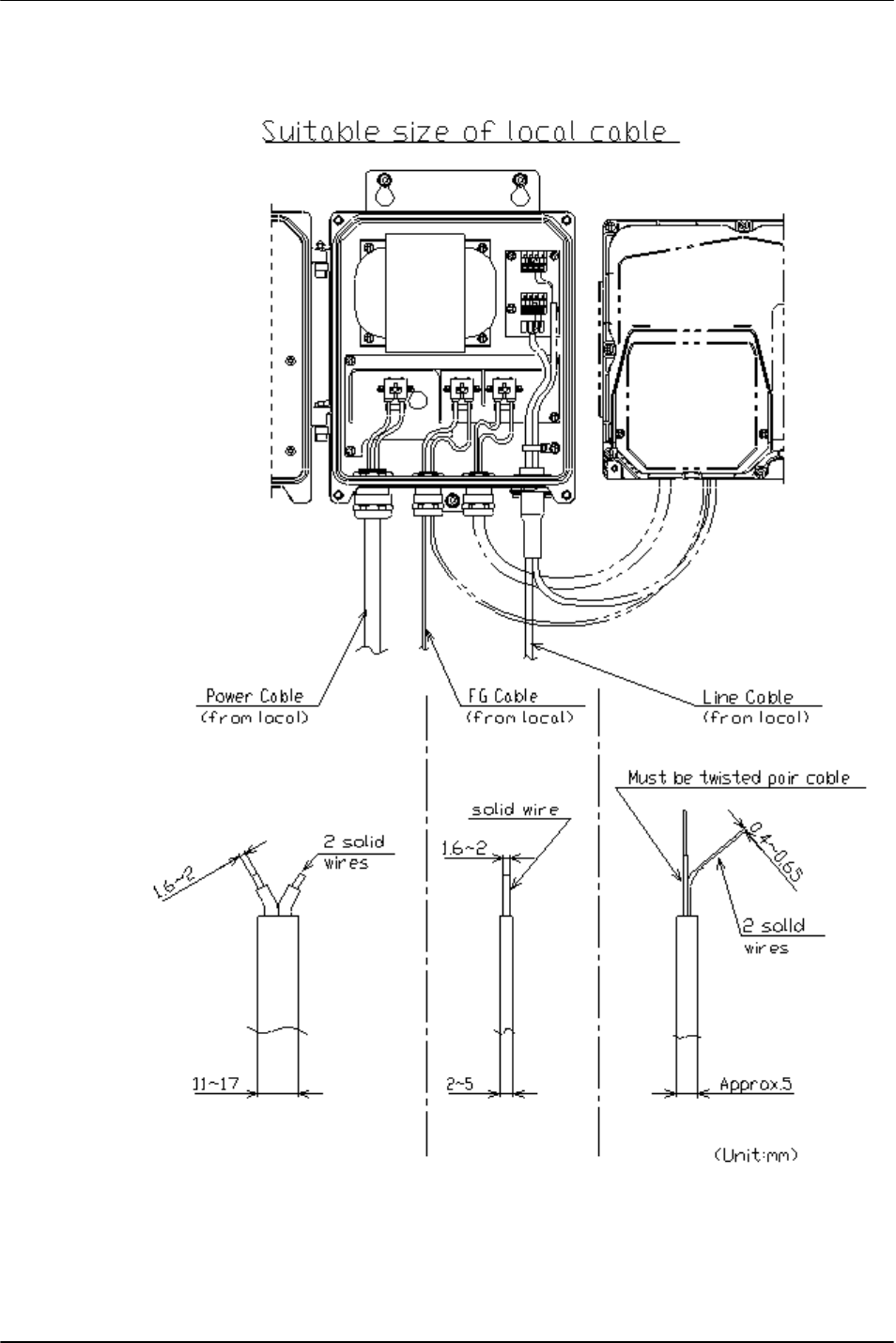
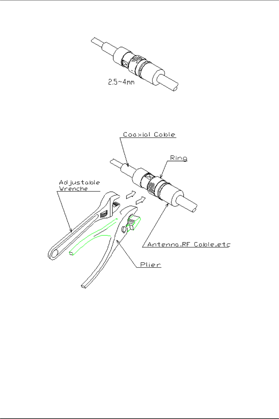
A.5 Suitable Size of the Local Cable
Figure 38: Local Cable Size
200mW RP Installation RPC/RP Manual
WLL-200mW-RP-IN-1.0 25July2000
3-38
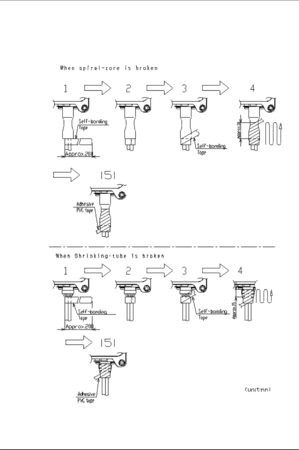
A.6 Tape Wrapping
If there is something wrong with the bushing, wrap the self-bonding tape and the
adhesive PVC tape as shown in the figures below.
Figure 39: Wrapping For Broken Spiral-core and Shrinking-tube
RPC/RP Manual 200mW RP Installation
25July2000 WLL-200mW-RP-IN-1.0
3-39
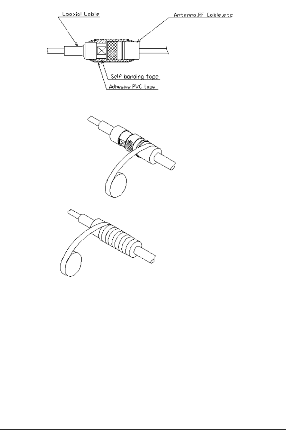
A.7 Water Proof of Antenna Cable
Figure 40: Water Proof of Antenna Cable
200mW RP Installation RPC/RP Manual
WLL-200mW-RP-IN-1.0 25July2000
3-40
Figure 41: Water Proof of Antenna Cable (Continued)
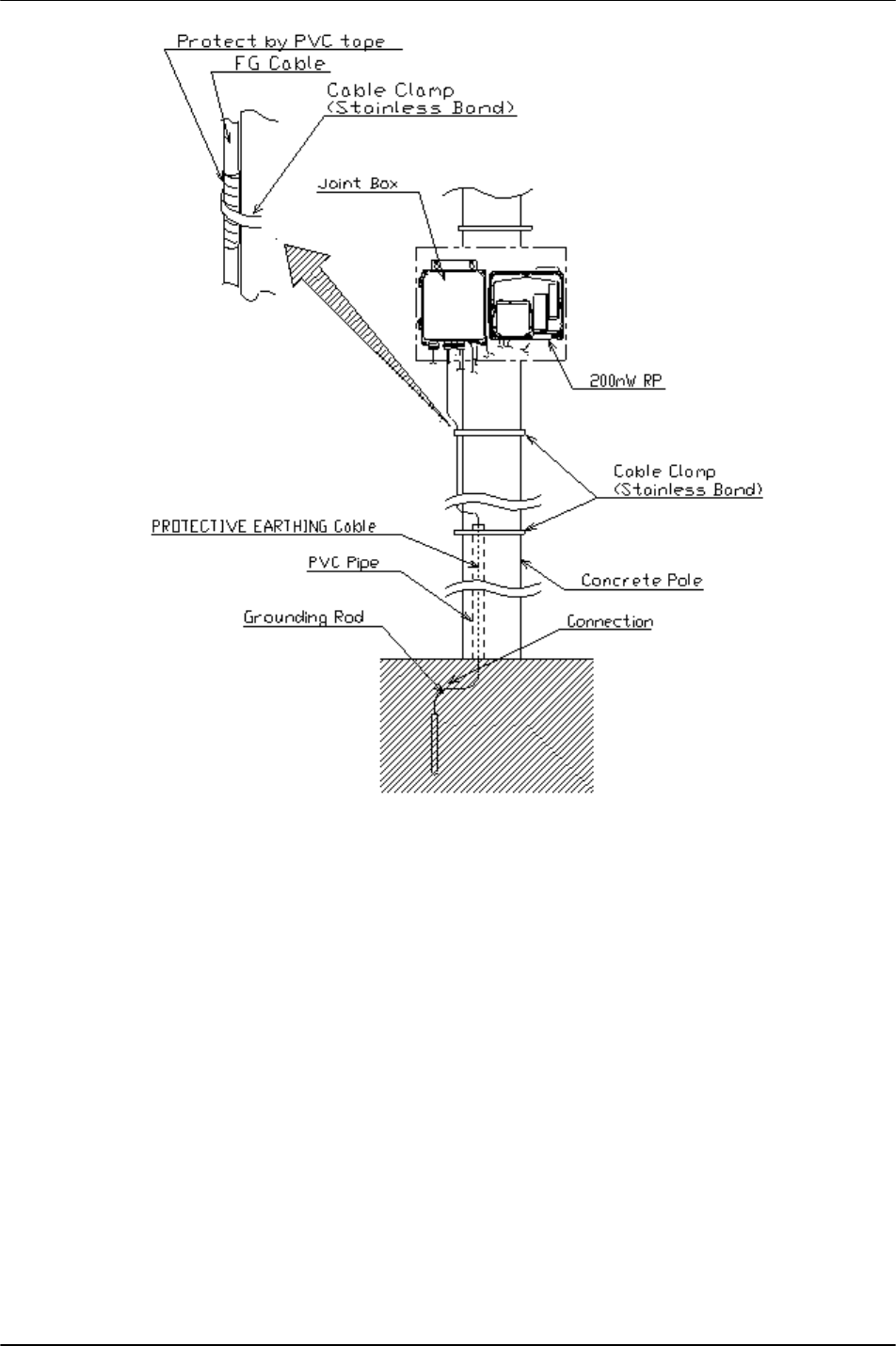
A.8 Grounding Protective Earthing Cable
Ground the PROTECTIVE EARTHING cable. Earth impedance is less than
100Ω.
RPC/RP Manual 200mW RP Installation
25July2000 WLL-200mW-RP-IN-1.0
3-41
Figure 42: Cable Grounding
200mW RP Installation RPC/RP Manual
WLL-200mW-RP-IN-1.0 25July2000
3-42
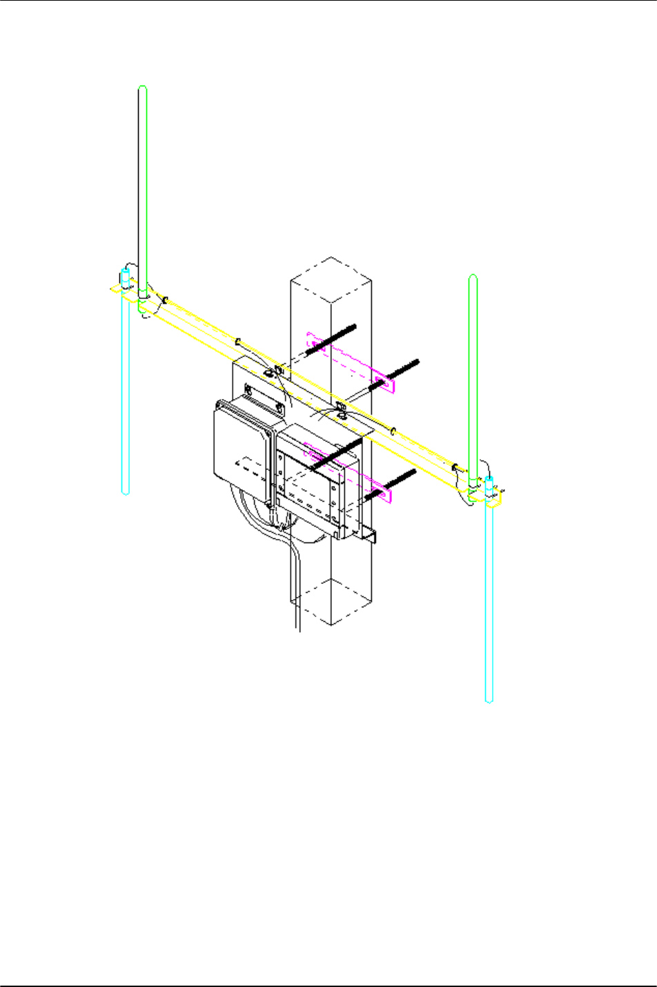
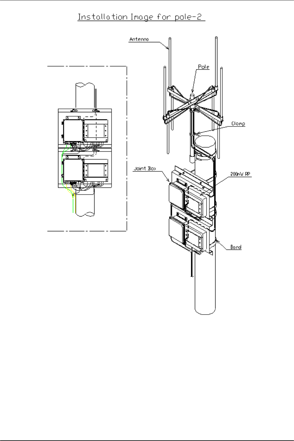
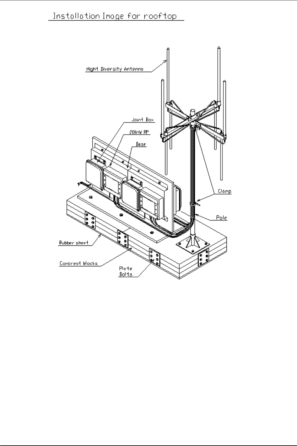
A.9 Installation Image
Figure 43: Pole Installation (1)
RPC/RP Manual 200mW RP Installation
25July2000 WLL-200mW-RP-IN-1.0
3-43
Figure 44: Pole Installation (2)
200mW RP Installation RPC/RP Manual
WLL-200mW-RP-IN-1.0 25July2000
3-44
Figure 45: Rooftop Installation

RPC/RP Manual 200mW RP Installation
25July2000 WLL-200mW-RP-IN-1.0
3-45