Ubiquiti Networks AF4X Dual Channel OFDM MIMO Point to Point Device User Manual airFiber X User Guide
Ubiquiti Networks, Inc. Dual Channel OFDM MIMO Point to Point Device airFiber X User Guide
Contents
- 1. Users Manual pt 1
- 2. Users Manual pt 2
- 3. Users Manual pt 3
- 4. Users Manual pt 4
- 5. Users Manual pt 5
Users Manual pt 2
7
Chapter 2: InstallationairFiber X User Guide
Ubiquiti Networks, Inc.
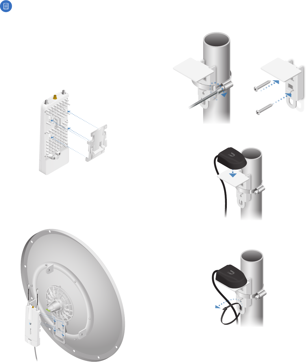
Mount to a RocketDish Antenna
This section applies only to the airFiber AF-4X and AF-5X
radios.
Note: If you are mounting the AF-4X or AF-5X on
a RocketDish equipped with the AF-5G-OMT-S45
Conversion Kit, the Universal Bracket is not needed.
Refer instead to the Mount to an airFiber X Antenna
section for instructions.
The RocketDish RD-5G30 antenna is shown in this section:
1. Position the Universal Bracket over the back of the
airFiber radio with the bracket clips over the radio
mounting tabs.
2. Push the bracket onto the airFiber radio until it locks in
place.
3. Attach the airFiber radio to the RocketDish mounting
bracket.
a. Align the mounting tabs on the Universal Bracket
with the RocketDish mounting bracket.
b. Slide the airFiber radio down to lock it into place.
Mount the External GPS Antenna
Locate a mounting point that has a clear view to the
sky, and is above and as far away as possible from the
airFiberX radio.
1. Attach the GPS Antenna Mount to the pole using the
metal strap, or attach it to a wall using the appropriate
fasteners (notincluded).
2. Place the External GPS Antenna on the mount.
3. Secure the cable of the External GPS Antenna to the
mount with a Cable Tie.
8
Chapter 2: Installation airFiber X User Guide
Ubiquiti Networks, Inc.
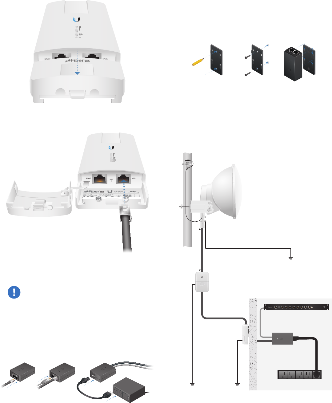
Connecting Power over Ethernet
1. Lift the release latch on the bottom of the airFiberX
radio and slide the Port Cover off.
2. Connect an outdoor, shielded Ethernet cable to the
DATA port.
3. Connect the other end of the cable from the DATA port
to the Ethernet port labeled POE on the airFiber PoE
Adapter.
WARNING: Use only the included airFiber PoE
Adapter, Model: GP-H240-100G-4. Failure to do
so can damage the unit and void the product
warranty.
4. Connect an Ethernet cable from your LAN to the
adapter’s LAN port.
5. Connect the Power Cord to the adapter’s power port.
Connect the other end of the Power Cord to a power
outlet.
Mount the PoE Adapter (Optional)
1. Remove the Mounting Bracket from the adapter, place
the bracket at the desired location, and mark the
two holes.
2. Pre-drill the holes if necessary, and secure the bracket
using two fasteners (not included).
3. Align the adapter’s slots with the tabs of the Mounting
Bracket, and then slide the adapter down.
Surge Protection
For added protection, install two surge suppressors, such
as the Ubiquiti Ethernet Surge Protector, model ETH-SP,
at the end of each link. Install the first surge protector
within one meter of the airFiber DATA port, and install the
second surge protector at the ingress point of the location
housing the wired network equipment.
Ground to Pole, Tower,
or Grounding Block:
Max. 1 m from AF-5X
Max. 1 m
airFiber
PoE Adapter
EdgeRouter™
Power Source
ETH-SP
GPS Antenna
ETH-SP
AF-5X
Mounted on
AF-5G23-S45
9
Chapter 2: InstallationairFiber X User Guide
Ubiquiti Networks, Inc.
Alignment
Tips
• To accurately align the airFiberX radios for best
performance, you MUST align only one end of the link at
a time.
• You may need to use additional hardware to
compensate for issues such as the improper orientation
of a mounting pole or significant elevation differences
between airFiberX radios.
Note: If you have AF-5X radios mounted in an
airFiber Multiplexer (AF-MPx4 or AF-MPx8),
perform the procedure in “Establishing a Link”
on page9 on one radio only. This will help
ensure maximum success in registrations. Refer to
“AF-5X and airFiber Multiplexer” on page 45
for additional information on airFiber Multiplexer
installation.
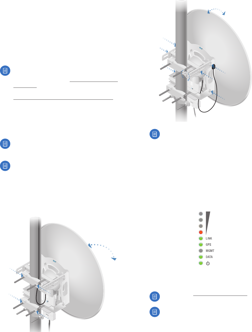
Establishing a Link
Adjust the positions of the Master and the Slave to
establish a link.
Note: The Master must be aimed first at the Slave
because the Slave does not transmit any RF signal
until it detects transmissions from the Master.
Note: The airFiber X antenna AF-5G30-S45 is
shown in the following steps. Instructions for other
antennas are similar. For complete details, refer to
the Quick Start Guide for your specific model.
1. Master Visually aim the Master at the Slave. To adjust
the Master’s position:
a. Loosen the four pole clamp nuts, and rotate the
airFiber antenna on the pole to align the azimuth.
b. Loosen the six elevation bolts, and use the hex nut
on the elevation rod to adjust the elevation.
Note: Do NOT make simultaneous adjustments
on the Master and Slave.
2. Slave Visually aim the Slave at the Master. To adjust the
Slave’s position:
a. Loosen the four pole clamp nuts, and rotate the
airFiber antenna on the pole to align the azimuth.
b. Loosen the six elevation bolts, and use the hex nut
on the elevation rod to adjust the elevation.
3. Check to see if a link is established. Ensure that the LINK
LED is solidly lit green and the Signal LEDs of the Slave
are displaying signal levels.
4. Slave Aim the Slave at the Master to achieve the
strongest signal level on the Master.
Note: Refer to “Signal LEDs” on page 2 for
details on the signal values.
Note: Maximum signal strength can best be
achieved by iteratively sweeping through both
azimuth and elevation.
5. Master Aim the Master at the Slave to achieve the
strongest signal level on the Slave.
10
Chapter 2: Installation airFiber X User Guide
Ubiquiti Networks, Inc.
6. Repeat steps 4 and 5 until you achieve an optimal link,
with all four Signal LEDs solidly lit. This ensures the best
possible data rate between the airFiberX radios.
7. Lock the alignment on both airFiber antennas by
tightening all the nuts and bolts.
8. Observe the Signal LEDs of each airFiberX radio
to ensure that the values remain constant while
tightening the nuts and bolts. If any LED value changes
during the locking process, loosen the nuts and bolts,
finalize the alignment of each airFiber antenna again,
and retighten the nuts and bolts.
Refer to the following chapters of this User Guide for
details on the airFiber Configuration Interface:
• “Main Tab” on page 13
• “Wireless Tab” on page 17
• “Network Tab” on page 21
• “Advanced Tab” on page 23
• “Services Tab” on page 27
• “System Tab” on page 31
• “Tools” on page 35
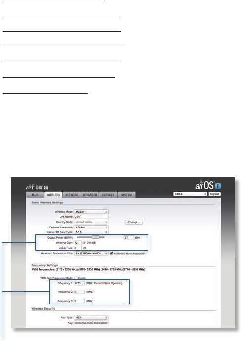
Installer Compliance Responsibility
Devices must be professionally installed and it is the
professional installer’s responsibility to make sure the
device is operated within local country regulatory
requirements.
The Output Power, Antenna Gain, Cable Loss, and Frequency
fields are provided to the professional installer to assist in
meeting regulatory requirements.
11
Chapter 3: NavigationairFiber X User Guide
Ubiquiti Networks, Inc.
Chapter 3: Navigation
The airFiber Configuration Interface is an advanced
operating system capable of powerful wireless and
routing features, built upon a simple and intuitive user
interface foundation.
The airFiberX radio uses the airFiber Configuration
Interface for easy configuration and management via a
web browser.
There are two ways to access the airFiber Configuration
Interface:
• Management Port Enabled by default. Use a direct
connection to the Management port for out-of-band
management.
• In-Band Management Enabled by default. In-band
management is available through the local Data port
or the Data port at the other end of the link. You can
disable it on the Network tab. (See “Management
Network Settings” on page 21 for more details.)
Accessing the airFiber Configuration
Interface
Connect to the airFiber Configuration Interface.
1. Make sure that your host machine is connected to the
LAN that is connected to the Management port on
theairFiberX radio.
2. Configure the Ethernet adapter on your host system
with a static IP address on the 192.168.1.x subnet (for
example, 192.168.1.100).
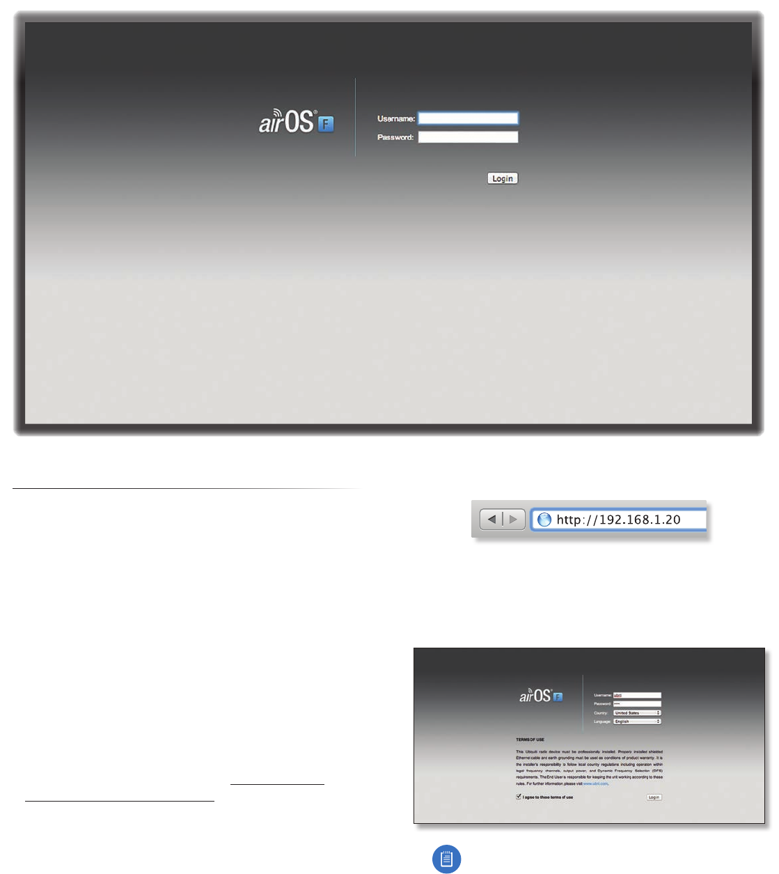
3. Launch your web browser. Type http://192.168.1.20 in
the address field and press enter (PC) or return (Mac).
4. Upon initial login, the Terms of Use appear on the login
screen. Enter ubnt in the Username and Password fields,
and select the appropriate choices from the Country
and Language drop-down lists. Check the box next to
Iagree to these terms of use, and click Login.
Note: U.S. product versions are locked to the U.S.
Country Code to ensure compliance with FCC
regulations.
5. The airFiber Configuration Interface will appear,
allowing you to customize your settings as needed.
12
Chapter 3: Navigation airFiber X User Guide
Ubiquiti Networks, Inc.
Product Verification
The airFiber Configuration Interface will verify whether a
product is genuine or counterfeit.
For a genuine airFiberX radio, the airFiber Configuration
Interface will display a Genuine Product logo in the lower
left corner of the screen.
For any product that is not an official Ubiquiti product, the
airFiber Configuration Interface will display a counterfeit
warning. Please contact Ubiquiti at support@ubnt.com
regarding this product.
Note: For product models introduced prior to 2012,
the airFiber Configuration Interface will NOT display
any logo in the lower left corner of the screen.
Interface Tabs
The airFiber Configuration Interface contains six main
tabs, each of which provides a web-based management
page to configure a specific aspect of the airFiberX radio.
This User Guide covers each tab with a chapter. For details
on a specific tab, refer to the appropriate chapter.
• Main The “Main Tab” on page 13 displays device
status, statistics, and network monitoring links.
• Wireless The “Wireless Tab” on page 17 configures
basic wireless settings, including the wireless mode, link
name, frequency, output power, speed, and wireless
security.
• Network The “Network Tab” on page 21 configures
the management network settings, Internet Protocol (IP)
settings, management VLAN, and automatic IP aliasing.
• Advanced The “Advanced Tab” on page 23
provides more precise wireless interface controls,
including advanced wireless settings and advanced
Ethernet settings.
• Services The “Services Tab” on page 27 configures
system management services: Ping Watchdog, Simple
Network Management Protocol (SNMP), servers (web,
SSH, telnet), Network Time Protocol (NTP) client,
Dynamic Domain Name System (DDNS) client, system
log, and device discovery.
• System The “System Tab” on page 31 controls
system maintenance routines, administrator account
management, location management, device
customization, firmware update, and configuration
backup. You can also change the language of the web
management interface.
Each page also contains network administration and
monitoring tools:
• “Align Antenna” on page 35
• “Discovery” on page 36
• “Ping” on page 36
• “Traceroute” on page 36
• “airView” on page 36
13
Chapter 4: Main TabairFiber X User Guide
Ubiquiti Networks, Inc.
Chapter 4: Main Tab
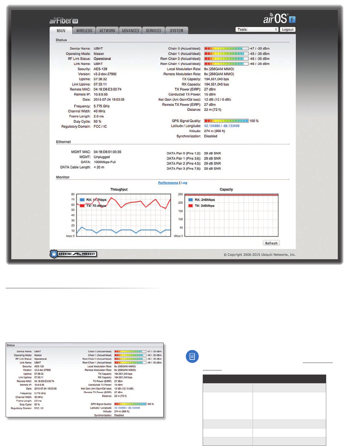
The Main tab displays a summary of the link status
information, current values of the basic configuration
settings, network settings and information, and traffic
statistics.
Status
Device Name Displays the customizable name or
identifier of the device. The Device Name (also known
as host name) is displayed in registration screens and
discovery tools.
Operating Mode Displays the mode of the airFiberX
radio: Slave, Master, or Reset.
RF Link Status Displays the status of the airFiberX radio:
RFOff, Syncing, Beaconing, Registering, Enabling, Listening,
Operational, DFS CAC, or RADAR Detected.
Note: Most of the RF Link Statuses map to specific
flash rates of the Link Status LED (See “LEDs” on
page 2 for more details.)
Status Flash Rate of LED
RF Off Off
Syncing
DFS countries only:
• DFS CAC
• RADAR Detected
Short Flash (1:3 on/off cycle)
Beaconing Normal Flash (1:1 on/off cycle)
Registering Long Flash (3:1 on/off cycle)
Operational On
14
Chapter 4: Main Tab airFiber X User Guide
Ubiquiti Networks, Inc.
The following applies to the AF-5X only:
When the AF-5X operates in a DFS country and within a
valid DFS band for that country, it performs a Channel
Availability Check (CAC) before operating. The rules vary
by country and frequency, but in general:
- FCC domains If the AF-5X operates in a DFS band
(5.2GHz or 5.4GHz band), the AF‑5X performs a
60-second check on the Masteronly.
- ETSI domains For most frequencies, the AF-5X
performs a 60-second check on the Master and Slave;
however, if it operates in the 5600‑5650 MHz range,
then the AF-5X performs a 10-minute check.
While the AF-5X is performing this check, the RF Link
Status displays DFS CAC, and the RF Link Timeout is
displayed.
If radar is detected, the RF Link Status displays RADAR
Detected, and the RF Link Timeout is displayed.
RF Link Timeout (Available only if the RF Link Status
is DFS CAC or RADAR Detected.) During the DFS CAC or
RADARDetected state, the RF Link Timeout counts down
the time remaining before the airFiberX radio can move
to the next RF link state.
Link Name Displays the name of your link.
Security AES-128 is enabled at all times.
Version Displays the airFiber Configuration Interface
software version.
Uptime This is the total time the device has been running
since the latest reboot (when the device was powered up)
or software upgrade. The time is displayed in days, hours,
minutes, and seconds.
Link Uptime This is the total time the airFiber link has
been continuously operational. The time is displayed in
days, hours, minutes, and seconds.
Remote MAC Displays the Management Ethernet MAC
address of the remote airFiberX radio.
Remote IP Displays the Management Ethernet IP address
of the remote airFiberX radio.
Date Displays the current system date and time. The
date and time are displayed in YEAR‑MONTH‑DAY
HOURS:MINUTES:SECONDS format. The system date and
time is retrieved from the Internet using NTP (Network
Time Protocol). The NTP Client is enabled by default on the
Services tab. The airFiberX radio doesn’t have an internal
clock, and the date and time may be inaccurate if the
NTP Client is disabled or the device isn’t connected to the
Internet.
Frequency (Available if split frequencies are not enabled.)
Displays the current frequency. The airFiberX radio uses
the radio frequency specified to transmit and receivedata.
TX Frequency (Available if split frequencies are enabled.)
Displays the frequency that the airFiberX radio uses to
transmit data.
RX Frequency (Available if split frequencies are enabled.)
Displays the frequency that the airFiberX radio uses to
receivedata.
Channel Width Size of the channel in MHz.
Frame Length Displays the currently configured frame
length of the radio: 2.0ms, 2.5ms, 4.0ms, or 5ms. Longer
frame lengths result in higher throughput for a given
configuration, but also result in slightly higher latency.
Duty Cycle Displays the duty cycle.
Regulatory Domain Displays the regulatory domain
(FCC/IC, ETSI, or Other), as determined by country
selection.
Chain 0/1 (Actual/Ideal) Displays the actual and ideal
power levels (in dBm) of the received signal for each chain.
The actual number indicates the current RX signal
strength. The ideal number is the RX signal strength of a
perfectly aligned link. These two numbers indicate exactly
how many dB out of alignment the system is.
When the link is aimed correctly, the bar graphs are full-
scale. If the bar graphs are not full-scale, they indicate that
your link is not optimally aimed.
Rem Chain 0/1 (Actual/Ideal) Displays the actual and
ideal power levels (in dBm) of the received signal for each
chain of the remote airFiberX radio. The bar graphs will
display as full-scale once the link is aimed correctly.
Local Modulation Rate Displays the modulation rate:
• 8x (256QAM MIMO)
• 6x (64QAM MIMO)
• 4x (16QAM MIMO)
• 2x (QPSK MIMO)
• 1x (½ Rate QPSK xRT™*)
• ¼x (¼ Rate QPSK xRT)
*xtreme Range Technology
If Automatic Rate Adaptation is enabled on the Wireless
tab, then Local Modulation Rate displays the current speed
in use and depends on the Maximum Modulation Rate
specified on the Wireless tab and current link conditions.
Remote Modulation Rate Displays the modulation rate
of the remote airFiberX radio:
• 8x (256QAM MIMO)
• 6x (64QAM MIMO)
• 4x (16QAM MIMO)
• 2x (QPSK MIMO)
• 1x (½ Rate QPSK xRT)
• ¼x (¼ Rate QPSK xRT)
TX Capacity Displays the potential TX throughput, how
much the airFiberX radio can send, after accounting for
the modulation and error rates.