Ubiquiti Networks AF4X Dual Channel OFDM MIMO Point to Point Device User Manual airFiber X User Guide
Ubiquiti Networks, Inc. Dual Channel OFDM MIMO Point to Point Device airFiber X User Guide
Contents
- 1. Users Manual pt 1
- 2. Users Manual pt 2
- 3. Users Manual pt 3
- 4. Users Manual pt 4
- 5. Users Manual pt 5
Users Manual pt 3
15
Chapter 4: Main TabairFiber X User Guide
Ubiquiti Networks, Inc.
RX Capacity Displays the potential RX throughput, how
much the airFiberX radio can receive, after accounting for
the modulation and error rates.
TX Power (EIRP) Displays the current average transmit
output power (in dBm) of the airFiberX radio.
Note: If “(Limited)” is displayed, the transmit output
power has been limited to a value less than the
selected value, to comply with regulatory region
requirements. For a list of maximum output power
values by country and region, refer to “Frequency
Ranges and Power Levels per Country/Region” on
page 63.
Conducted TX Power Displays the conducted transmit
power out of the radio before any antenna gain.
Net Gain Displays the airFiberX radio’s net antenna gain,
which is the antenna gain minus cable loss. Antenna
gain (the gain of the antenna being used) and cable loss
(the loss in the cable from the radio to the antenna) are
set using the Antenna Gain and Cable Loss fields on the
Wireless tab.
Remote TX Power (EIRP) Displays the current average
transmit output power (in dBm) of the remote airFiberX
radio.
Distance Displays the distance between the airFiberX
radios.
GPS Signal Quality Displays Global Positioning System
(GPS) signal quality as a percentage value on a scale of
0-100%.
Latitude/Longitude Based on GPS tracking, reports the
device’s current latitude and longitude. Clicking the link
opens the reported latitude and longitude in a browser
using Google Maps™ (http://maps.google.com).
Altitude Based on GPS tracking, reports the device’s
current altitude relative to sea level.
Synchronization airFiber uses GPS to synchronize the
timing of its transmissions. By default, this option is
disabled.
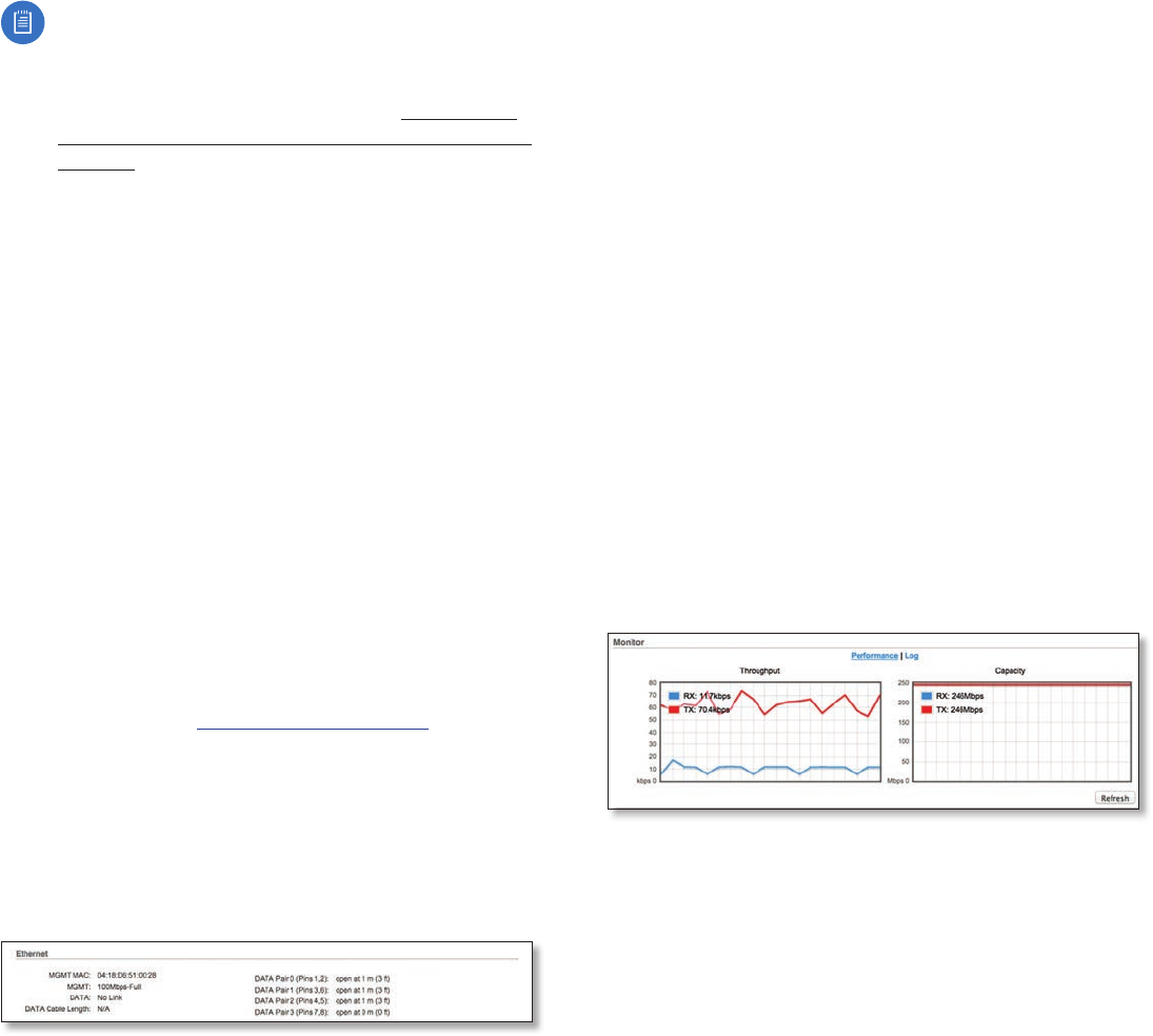
Ethernet
MGMT MAC Displays the MAC address of the
Management port.
MGMT Displays the speed and duplex of the
Managementport.
DATA Displays the speed and duplex of the Data port.
DATA Cable Length Displays the Ethernet cable length
from radio to remote port. This is displayed only for cables
longer than 20 m.
DATA Pair 0 (Pins 1,2) If the cable is functioning properly,
displays the SNR of the twisted pair; if the cable has a
fault, displays the fault (“open” or “short”) and the distance
at which the fault has occurred. If the remote port is
administratively shut down, this field displays “normal”.
DATA Pair 1 (Pins 3,6) If the cable is functioning properly,
displays the SNR of the twisted pair; if the cable has a
fault, displays the fault (“open” or “short”) and the distance
at which the fault has occurred. If the remote port is
administratively shut down, this field displays “normal”.
DATA Pair 2 (Pins 4,5) If the cable is functioning properly,
displays the SNR of the twisted pair; if the cable has a
fault, displays the fault (“open” or “short”) and the distance
at which the fault has occurred. If the remote port is
administratively shut down, this field displays “normal”.
DATA Pair 3 (Pins 7,8) If the cable is functioning properly,
displays the SNR of the twisted pair; if the cable has a
fault, displays the fault (“open” or “short”) and the distance
at which the fault has occurred. If the remote port is
administratively shut down, this field displays “normal”.
Monitor
There are two monitoring tools accessible via the links
on the Main tab. The default is Performance, which is
displayed when you first open the Main tab.
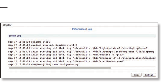
Performance
Throughput and Capacity charts display the current and
potential data traffic.
Throughput
Throughput displays the current data traffic on the Data
port in both graphical and numerical form. The chart scale
and throughput dimension (Bps, Kbps, Mbps) change
dynamically depending on the mean throughput value.
The statistics are updated automatically.
Capacity
Capacity displays the potential data traffic on the Data
port in both graphical and numerical form. The chart scale
and throughput dimension (Bps, Kbps, Mbps) change
dynamically depending on the mean throughput value.
The statistics are updated automatically.
Refresh If there is a delay in the automatic update, click
Refresh to manually update the statistics.
16
Chapter 4: Main Tab airFiber X User Guide
Ubiquiti Networks, Inc.
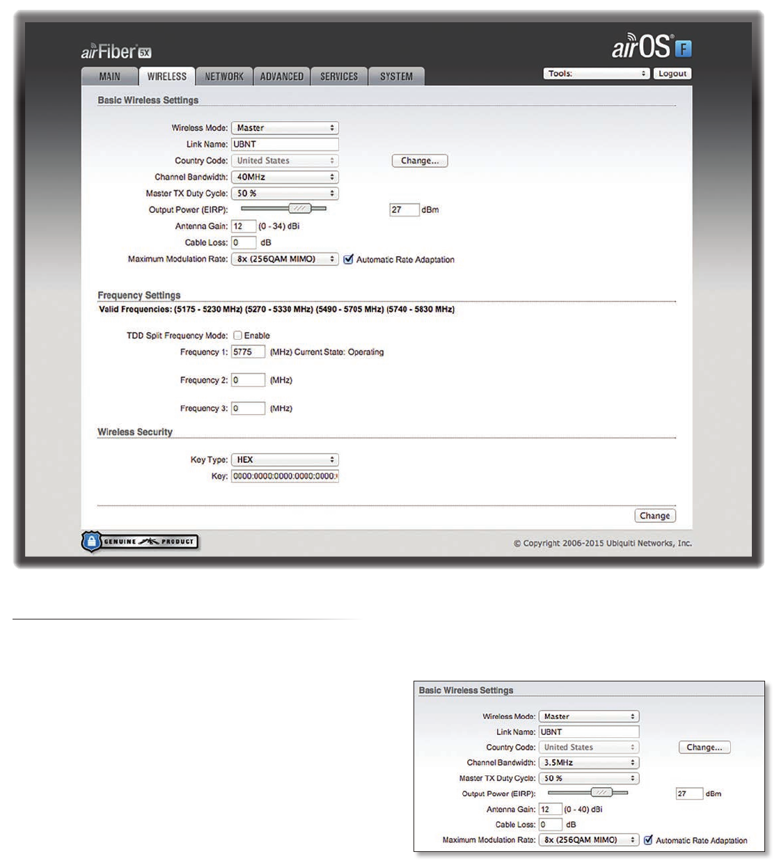
Log
When logging is enabled (see “System Log” on page
29 to enable logging), this option lists all registered
system events. By default, logging is not enabled.
Clear To delete all entries in the system log, click Clear.
Refresh To update the log content, click Refresh.
17
Chapter 5: Wireless TabairFiber X User Guide
Ubiquiti Networks, Inc.
Chapter 5: Wireless Tab
The Wireless tab contains options to set up the wireless
part of the link. This includes wireless mode, link name,
frequencies, output power, speed, and wireless security.
Change To save or test your changes, click Change.
A new message appears. You have three options:
• Apply To immediately save your changes, click Apply.
• Test To try the changes without saving them, click Test.
To keep the changes, click Apply. If you do not click
Apply within 180 seconds (the countdown is displayed),
the airFiberX radio times out and resumes its earlier
configuration.
• Discard To cancel your changes, click Discard.
Write down the settings you configure on the Wireless tab.
You will need to enter the same settings on the airFiberX
radio at the other end of your PtP link. The exceptions are
as follows:
• Wireless Mode Configure one airFiberX radio as the
Master and the other as the Slave.
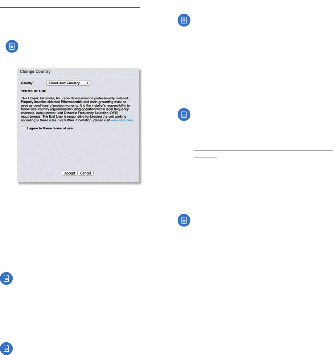
Basic Wireless Settings
In this section, configure the basic wireless settings, such
as wireless mode, link name, country code, frequencies,
output power, speed, and gain.
Wireless Mode By default, the Wireless Mode is Slave. You
must configure one airFiberX radio as Master because
each PtP link must have one Master.
Link Name Enter a name for your PtP link. This name
must be the same on both Master and Slave radios in
order for them to connect.
18
Chapter 5: Wireless Tab airFiber X User Guide
Ubiquiti Networks, Inc.
Country Code Each country has its own power level
and frequency regulations. To ensure the airFiberX radio
operates under the necessary regulatory compliance rules,
you must select the country where your device will be used.
The frequency settings and output power limits will
be tuned according to the regulations of the selected
country. For details, refer to this table, “Frequency Ranges
and Power Levels per Country/Region” on page 63.
This radio is restricted to use with a license and to use only in
certain EU countries or geographical areas of EU countries.
• Change To select a new country, click Change.
Note: U.S. product versions are locked to the U.S.
Country Code to ensure compliance with FCC
regulations.
- Country Select the new country.
- I agree to these terms of use Check this box; you
must agree to the Terms of Use to use the product.
- Accept Saves your change.
- Cancel Discards your change.
Channel Bandwidth Select the appropriate channel size:
• AF-2X and AF-3X: 3.5, 5, 7, 10, 14, 20, 28, 30, 40, 50,
or 56 MHz
• AF-5X only: 5, 10, 20, 30, 40, or 50 MHz
Note:. The available channel bandwidths depend
on the regulatory requirements of the currently
selected country or region.
Frame Length (Available on AF-2X and AF-3X only.) Use
this to specify the frame length of the radio: default,
2.0ms, 2.5ms, 4.0ms, or 5ms. The frame length must be
the same on both Master and Slave radios. The default
value corresponds to 5ms for the 3.5MHz and 5MHz
bandwidths, or 2.0ms for all other bandwidths.
Note:. The AF-5X uses a frame length of 2.0ms (this
value cannot be changed).
Master TX Duty Cycle Use this to change the duty cycle
of the RF link (the Master’s TX percentage). Choose one of
the following values: 25%, 33%, 50%, 67%, or 75%.
Output Power (EIRP) Defines the maximum average
transmit output power (in dBm) of the airFiberX radio.
To specify the output power, use the slider or manually
enter the output power value. The transmit power level
maximum is limited according to country regulations.
Note: The Antenna Gain and Cable Loss should be
configured before the Output Power. This is because
the range of the Output Power field is affected by
the Antenna Gain and Cable Loss values – changing
the antenna gain or cable loss adjusts the maximum
and minimum values you can select using the
Output Power slider. Since the Output Power
already includes the antenna gain and cable loss, it
represents EIRP; therefore, the value of Output Power
is actually the total power the radio is transmitting
over the air. The current transmit power is displayed
by the TX Power EIRP setting on the Main tab.
Note: The airFiberX radio may limit the output
power to a value less than the value specified
by this field, to comply with regulatory region
requirements. For a list of maximum output power
values by country and region, refer to “Frequency
Ranges and Power Levels per Country/Region” on
page 49.
Antenna Gain Enter the gain in dBi of the antenna that is
used in your installation. An improper value could cause
DFS false detections when operating on DFS frequencies.
Cable Loss Enter the cable loss in dB of the cable that is
used in your installation. An improper value could cause
DFS false detections when operating on DFS frequencies.
Note: If you are using the airFiber AF-5X radio with
an airFiber NxN Multiplexer, set the CableLoss to a
value that includes the additional cable loss due to
the Multiplexer. The additional cable loss (in dB) is:
• 4.1 for the AF-MPx4, or
• 7.2 for the AF-MPx8
Maximum Modulation Rate or Modulation Rate Higher
modulations support greater throughput but generally
require stronger RF signals and a higher Signal-to-Noise
Ratio (SNR). By default, Automatic Rate Adaptation is
enabled, and Maximum Modulation Rate is displayed. This
allows the airFiberX radio to automatically adjust the
modulation rate to changing RF signal conditions. Under
certain conditions, you may prefer to lock the Maximum
Modulation Rate to a lower setting to improve link
performance.
When Automatic Rate Adaptation is disabled, Modulation
Rate is displayed. Lock the Modulation Rate to the setting
of your choice.
19
Chapter 5: Wireless TabairFiber X User Guide
Ubiquiti Networks, Inc.
Select one of the available modulation rates:
• 8x (256QAM MIMO)
• 6x (64QAM MIMO)
• 4x (16QAM MIMO)
• 2x (QPSK MIMO)
• 1x (½ Rate QPSK xRT)
• ¼x (¼ Rate QPSK xRT)
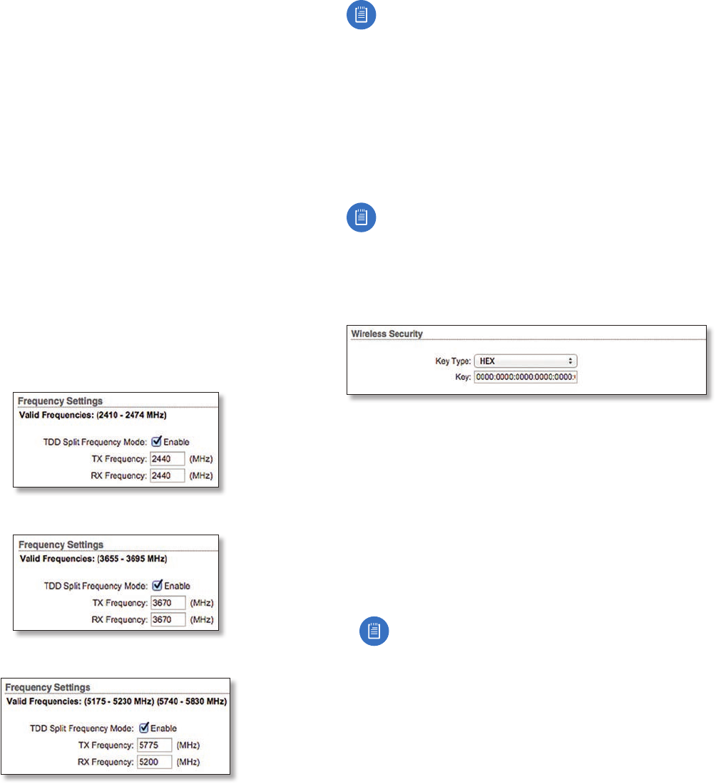
Frequency Settings
The Valid Frequencies for your Country Code selection are
displayed. Ensure that you use frequencies that comply
with the local country regulations.
TDD Split Frequency Mode This option lets you
configure separate frequencies for TX and RX. To configure
split frequencies, enable this option and select a different
RX frequency on each side of the link. This feature is useful
if both sides of the link do not have a common, clean
frequency. It is important for the RX frequency to be
clean; if different frequencies are clean on each end of the
link, select the clean RX frequency on each end.
AF-2X Split Frequency Settings
AF-3X Split Frequency Settings
AF-5X Split Frequency Settings
Note for AF-5X only: Split frequency mode is not
available in DFS bands because the RX frequency
must match the TX frequency to allow the receiver
to scan for DFS on the TX frequency. In regions
where both DFS and non-DFS frequencies are
available, enabling split frequencies will disable any
DFS band frequencies. In regions where only DFS
frequencies are available, there will be no option to
turn on split frequencies.
Frequency Enter a valid frequency. The current state is
displayed.
Note: The Master and Slave should have the same
Frequency setting.
Wireless Security
airFiber uses 128-bit, AES (Advanced Encryption Standard)
encryption at all times.
Key Type Specifies the character format.
• HEX By default, this option uses hexadecimal
characters. 0-9, A-F, or a-f are valid characters.
• ASCII ASCII uses the standard English alphabet and
numeric characters (0-9, A-Z, or a-z).
Key Select the format of the MAC address.
• HEX Enter 16bytes (eight, 16-bit HEX values). You can
omit zeroes and use colons, similar to the IPv6 format.
The default is:
0000:0000:0000:0000:0000:0000:0000:0000
Note: The airFiber Configuration Interface
supports IPv6 formats excluding dotted quad and
“::” (double-colon) notation.
• ASCII Enter a combination of alphanumeric characters.
Using 128-bit SHA1 (Secure Hash Algorithm 1), the
airFiberX radio hashes the ASCII key to create a 128-bit
key for AES.
20
Chapter 5: Wireless Tab airFiber X User Guide
Ubiquiti Networks, Inc.
21
Chapter 6: Network Tab airFiber X User Guide
Ubiquiti Networks, Inc.
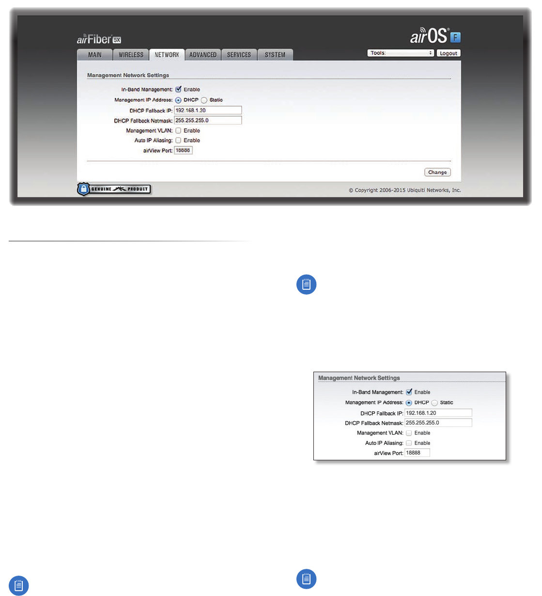
Chapter 6: Network Tab
The Network tab allows you to configure settings for the
management network. There are two ways to access the
airFiber Configuration Interface:
• Management Port Enabled by default. Use a direct
connection to the Management port for out-of-band
management.
• In-Band Management Enabled by default. In-band
management is available through the local Data port or
the Data port at the other end of the link.
The Management port and in-band management share
the default IP address of 192.168.1.20.
Change To save or test your changes, click Change.
A new message appears. You have three options:
• Apply To immediately save your changes, click Apply.
• Test To try the changes without saving them, click Test.
To keep the changes, click Apply. If you do not click
Apply within 180 seconds (the countdown is displayed),
the airFiberX radio times out and resumes its earlier
configuration.
• Discard To cancel your changes, click Discard.
Management Network Settings
In-Band Management Enabled by default. In-band
management is available through the local Data port or
the Data port at the other end of the link.
Note: If In-Band Management is enabled, ensure
that each airFiberX radio in a link has a unique
IP Address. If the airFiberX radios use the same IP
Address, you may lose access via the Data ports.
Management IP Address The airFiberX radio can use
a static IP address or obtain an IP address from its DHCP
server.
• DHCP Keep the default, DHCP, to use DHCP reservation
on your router to assign a unique IP Address. The local
DHCP server assigns a reserved IP address, gateway IP
address, and DNS address to the airFiberX radio.
Note: If you select the DHCP option, ensure that
you use DHCP reservation because if you do not
know the IP address, then the only way to manage
the airFiberX radio is to reset the airFiberX radio
to its factory default settings. (Press and hold
the Reset button for more than five seconds.)
Its default Management IP Address is reset to
192.168.1.20.
- DHCP Fallback IP Specify the IP address the
airFiberX radio should use if a DHCP server is not
found.
- DHCP Fallback Netmask Specify the netmask the
airFiberX radio should use if a DHCP server is not
found.
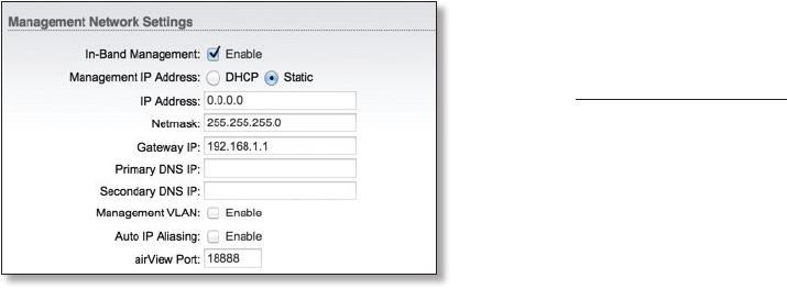
• Static Assign static IP settings to the airFiberX radio.
Note: IP settings should be consistent with the
address space of the airFiberX radio’s network
segment.
22
Chapter 6: Network Tab airFiber X User Guide
Ubiquiti Networks, Inc.
- IP Address Specify the IP address of the airFiberX
radio. This IP will be used for device management
purposes.
- Netmask When the netmask is expanded into its
binary form, it provides a mapping to define which
portions of the IP address range are used for the
network devices and which portions are used for host
devices. The netmask defines the address space of the
airFiberX radio’s network segment. The 255.255.255.0
(or “/24”) netmask is commonly used on many Class C
IP networks.
- Gateway IP Typically, this is the IP address of the host
router, which provides the point of connection to the
Internet. This can be a DSL modem, cable modem, or
WISP gateway router. The airFiberX radio directs data
packets to the gateway if the destination host is not
within the local network.
- Primary DNS IP Specify the IP address of the primary
DNS (Domain Name System) server.
- Secondary DNS IP Specify the IP address of the
secondary DNS server. This entry is optional and used
only if the primary DNS server is not responding.
Management VLAN If enabled, automatically creates a
management Virtual Local Area Network (VLAN).
• VLAN ID Enter a unique VLAN ID from 2 to 4094.
Auto IP Aliasing If enabled, automatically generates an
IP address for the corresponding WLAN/LAN interface.
The generated IP address is a unique Class B IP address
from the 169.254.X.Y range (netmask 255.255.0.0), which
is intended for use within the same network segment
only. The Auto IP always starts with 169.254.X.Y, with X
and Y as the last two octets from the MAC address of
the airFiberX radio. For example, if the MAC address is
00:15:6D:A3:04:FB, then the generated unique Auto IP will
be 169.254.4.251. (The hexadecimal value, FB, converts to
the decimal value,251.)
The Auto IP Aliasing setting can be useful because you
can still access and manage devices even if you lose,
misconfigure, or forget their IP addresses. Because an
Auto IP address is based on the last two octets of the MAC
address, you can determine the IP address of a device if
you know its MAC address.
airView Port The port number associated with the
airView spectrum analyzer tool. The default value is 18888.
For detailed information on the airView tool, refer to
“airView” on page 36.
23
Chapter 7: Advanced Tab airFiber X User Guide
Ubiquiti Networks, Inc.
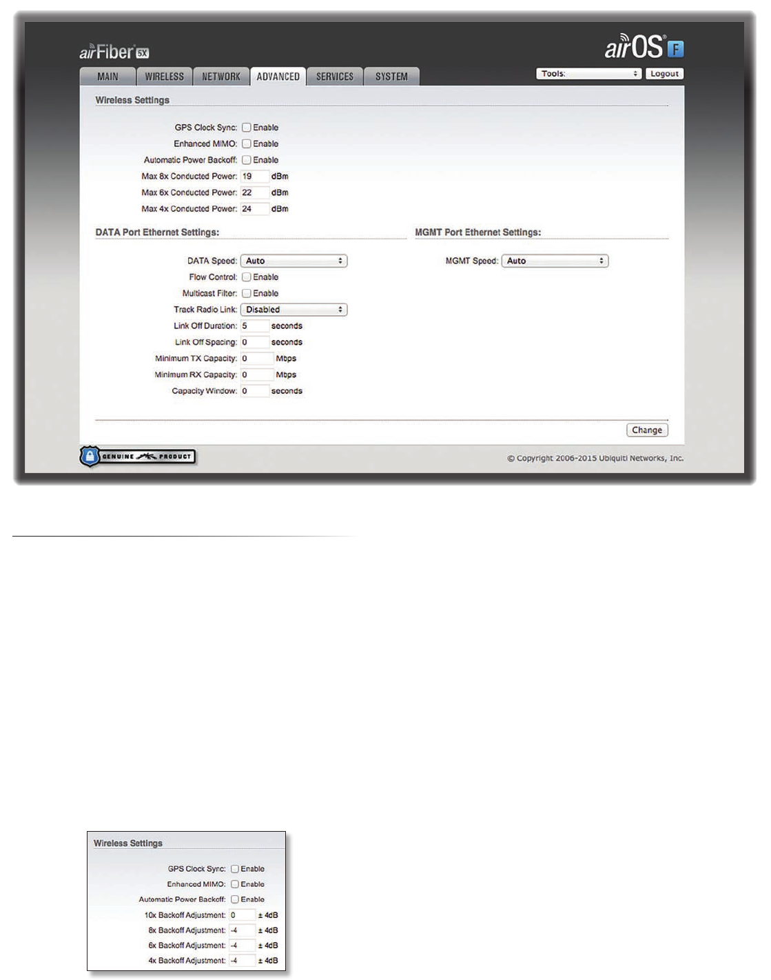
Chapter 7: Advanced Tab
The Advanced tab handles advanced wireless and Ethernet
settings. These settings should not be changed unless
you understand how the changes will affect the airFiberX
radio.
Change To save or test your changes, click Change.
A new message appears. You have three options:
• Apply To immediately save your changes, click Apply.
• Test To try the changes without saving them, click Test.
To keep the changes, click Apply. If you do not click
Apply within 180 seconds (the countdown is displayed),
the airFiberX radio times out and resumes its earlier
configuration.
• Discard To cancel your changes, click Discard.
Wireless Settings
GPS Clock Sync The airFiber uses GPS to synchronize
the timing of its transmissions. By default, this option is
disabled.
Automatic Power Backoff This feature allows the radio
to automatically adjust the maximum TX power per
modulation so that the radio never transmits at a higher
power than each modulation rate can decode. The default
values in the Max 8x/6x/4x Conducted Power fields are
values determined to work at all temperatures and all
frequencies supported by the radio.
It may, however, be possible to increase the maximum
TX power for one or more modulations based on your
radio’s operating environment. For example, if a radio
is running at 6x and trying to switch into 8x operation,
you can increase the Max 8x Conducted Power value 1dB
at a time to see if the radio can maintain 8x operation
(Automatic Power Backoff must be enabled to allow the
Max Conducted Power fields to be edited). The same can
be done with 6x and 4x up to the maximum conducted
power of the radio.
Max 8x/6x/4x Conducted Power The maximum
conducted power for the 8x/6x/4x modulation rates. Each
field is editable only if Automatic Power Backoff is enabled.
24
Chapter 7: Advanced Tab airFiber X User Guide
Ubiquiti Networks, Inc.
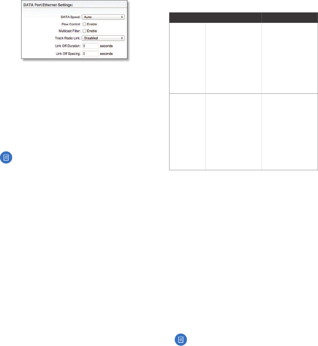
DATA Port Ethernet Settings
DATA Speed This is the speed of the Data port.
Thedefault is Auto. The airFiberX radio automatically
negotiates transmission parameters, such as speed and
duplex, with its counterpart. In this process, the networked
devices first share their capabilities and then choose the
fastest transmission mode they both support.
To manually specify the maximum transmission link
speed and duplex mode, select one of the following
options: 100 Mbps‑Full, 100Mbps‑Half, 10Mbps‑Full, or
10Mbps‑Half.
To disable the Ethernet data port, select Disabled.
Note: If Disabled is selected, ensure that the radio
is accessible using the Management Ethernet port
or over the RF link (with in-band management
enabled), or all communication with the radio will
be lost.
Full-duplex mode allows communication in both
directions simultaneously. Half-duplex mode allows
communication in one direction at a time, alternating
between transmission and reception.
Flow Control If enabled, the airFiberX radio generates
and responds to Ethernet layer PAUSE frames. The
airFiberX radio regulates inbound traffic from the
customer’s network to avoid buffer overflows within the
airFiberX radio. Flow control has the effect of controlling
the inter-packet spacing of packets headed into the
airFiber Data interface.
Multicast Filter If enabled, the filter blocks multicast
traffic from overloading the CPU when in-band
management is enabled. This allows the airFiberX radio
to be managed in-band when the customer’s network is
carrying large volumes of multicast traffic, such as IPTV.
The filter does not block multicast traffic going over
the radio; it simply blocks it from reaching the airFiber’s
management interface CPU.
Track Radio Link If this option is enabled, the airFiberX
radio disconnects the Data port’s Ethernet link when the
RF link is lost (The Management port is never disabled by
this option). The Track Radio Link option is useful because
it quickly indicates a “link lost” condition to the customer’s
routing equipment (such as a direct connection to
OSPF-enabled routers).
• Disabled The Track Radio Link option is disabled by
default. The Data port’s Ethernet link will always remain
up regardless of the RF link state.
• Use Timeout Duration This option is designed for use
by operators who are using in-band management. Two
timers control the Data port’s Ethernet link.
RF Link Ethernet Link Notes
Goes down for
the first time
The Ethernet link goes
down and remains
down for the number
of seconds specified by
the Link Off Duration
timer.
The Ethernet link will
then come back up
so that the airFiberX
radio can be managed
even when the RF link
is down.
Even if the RF link goes
back up before the
Link Off Duration timer
elapses, the Ethernet
link remains down.
The Ethernet link’s
downtime is long
enough to signal to
the customer’s routing
equipment that the
path is lost.
Goes down
for the
secondtime
The Ethernet link
remains up as long as
time remains on the
Link Off Spacing timer.
When the Link Off
Spacing timer elapses,
then the Ethernet link
goes down again for
the number of seconds
specified by the Link
Off Duration timer. (This
happens only if the RF
link is still down.)
The Ethernet link’s
uptime is long enough
so the operator has
enough time to access
the airFiberX radio,
make configuration
changes, and save those
changes.
Sufficient Ethernet link
uptime is vital when a
RF link is constantly up
and down.
If the Use Timeout Duration option is enabled, the Track
Radio Link option and the following timers are enabled:
- Link Off Duration The Link Off Duration timer
controls the length of time the Data port’s Ethernet
link will be down if the RF link goes down. Enter the
number of seconds that the Ethernet link should be
offline. For example, if this is set to 10seconds, then
when the RF link goes down, the Ethernet link will go
down and remain down for 10seconds (regardless of
the RF link state), and then it will go back up.
- Link Off Spacing
The Link Off Spacing timer controls
the length of time the airFiberX radio will wait before
allowing the Data port’s Ethernet link to go down for a
second time if the RF link goes down again. Enter the
minimum interval (in seconds) between offline events
of the Ethernet link, regardless of the RF link status.
The value for Link Off Spacing should be larger than the
value for Link Off Duration, and it should be enough
time for the operator to access the airFiberX radio,
make any configuration changes, and apply those
changes.
Note: If the Link Off Spacing timer is set to
0seconds, then the Ethernet link will only use the
Link Off Duration timer. If the Link Off Duration
timer is set to 10 seconds and the RF link goes
down, then the Ethernet link will go down for
10seconds and then go back up regardless of the
RF link state. If the RF link is still down, then the
Ethernet link will not go down again until the RF
link goes back up and then down again.
25
Chapter 7: Advanced Tab airFiber X User Guide
Ubiquiti Networks, Inc.
Here are a couple of examples involving the use of the
Use Timeout Duration option.
• Example #1
• Link Off Duration 5 seconds
• Link Off Spacing 60 seconds
The Data port’s Ethernet link will be initially
disconnected when the RF link first goes down. That
event will start a 60-second timer. The Ethernet link
will remain offline for 5seconds (regardless of the RF
link status) and then come back online. The Ethernet
link will remain online (regardless of the RF link
state) until the 60-second timer expires.
• Example #2
• Link Off Duration 20 seconds
• Link Off Spacing 120 seconds
The Data port’s Ethernet link will be initially
disconnected when the RF link first goes down. That
event will start a 120-second timer. The RF link goes
back up after 10 seconds; however, that does not
affect the Ethernet link. The Ethernet link will remain
offline for 20seconds and then come back online.
The RF link goes down again after 60 seconds;
however, that does not affect the Ethernet link.
The Ethernet link will then remain online until the
120-second timer expires.
• Enabled This option is designed for use by operators
who are not using in-band management. The Track
Radio Link option is enabled without timers, so the Data
port’s Ethernet link follows the RF link state exactly. If
the RF link goes down, then the Ethernet link goes down
and remains down until the RF link goes back up.
Minimum TX Capacity This is the minimum allowable TX
capacity before the link is dropped. If the capacity drops
below this threshold, the Ethernet link will be dropped.
Ifset to 0, then capacity will not be used; only the RF link
state will be used.
Minimum RX Capacity This is the minimum allowable RX
capacity before the link is dropped. If the capacity drops
below this threshold, the Ethernet link will be dropped.
Ifset to 0, then capacity will not be used; only the RF link
state will be used.
Capacity Window This is the number of continuous
seconds that the radio must remain under the minimum
TX or RX capacity before the link is dropped. If set to
0, then as soon as capacity drops below a set limit, the
Ethernet link will be dropped.
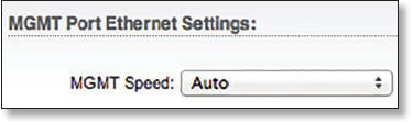
MGMT Port Ethernet Settings
MGMT Speed This is the speed of the Management
port. By default, the option is Auto. The airFiberX radio
automatically negotiates transmission parameters, such as
speed and duplex, with its counterpart. In this process, the
networked devices first share their capabilities and then
choose the fastest transmission mode they both support.
To manually specify the maximum transmission link
speed and duplex mode, select one of the following
options: 100 Mbps‑Full, 100Mbps‑Half, 10 Mbps‑Full,
or 10Mbps‑Half. If you are running extra long Ethernet
cables, a link speed of 10Mbps could help to achieve
better stability.
Full-duplex mode allows communication in both
directions simultaneously. Half-duplex mode allows
communication in one direction at a time, alternating
between transmission and reception.
26
Chapter 7: Advanced Tab airFiber X User Guide
Ubiquiti Networks, Inc.
27
Chapter 8: Services TabairFiber X User Guide
Ubiquiti Networks, Inc.
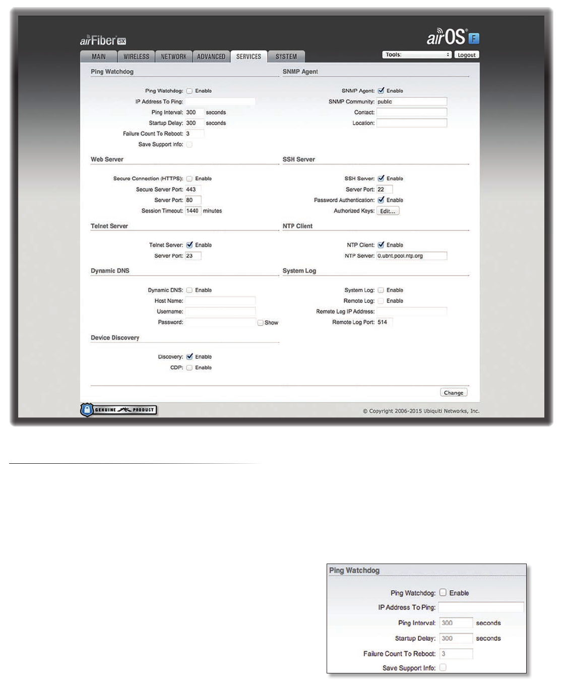
Chapter 8: Services Tab
The Services tab configures system management services:
Ping Watchdog, SNMP Agent, Web Server, SSH Server, Telnet
Server, NTP Client, Dynamic DNS, System Log, and Device
Discovery.
Change To save or test your changes, click Change.
A new message appears. You have three options:
• Apply To immediately save your changes, click Apply.
• Test To try the changes without saving them, click Test.
To keep the changes, click Apply. If you do not click
Apply within 180 seconds (the countdown is displayed),
the airFiberX radio times out and resumes its earlier
configuration.
• Discard To cancel your changes, click Discard.
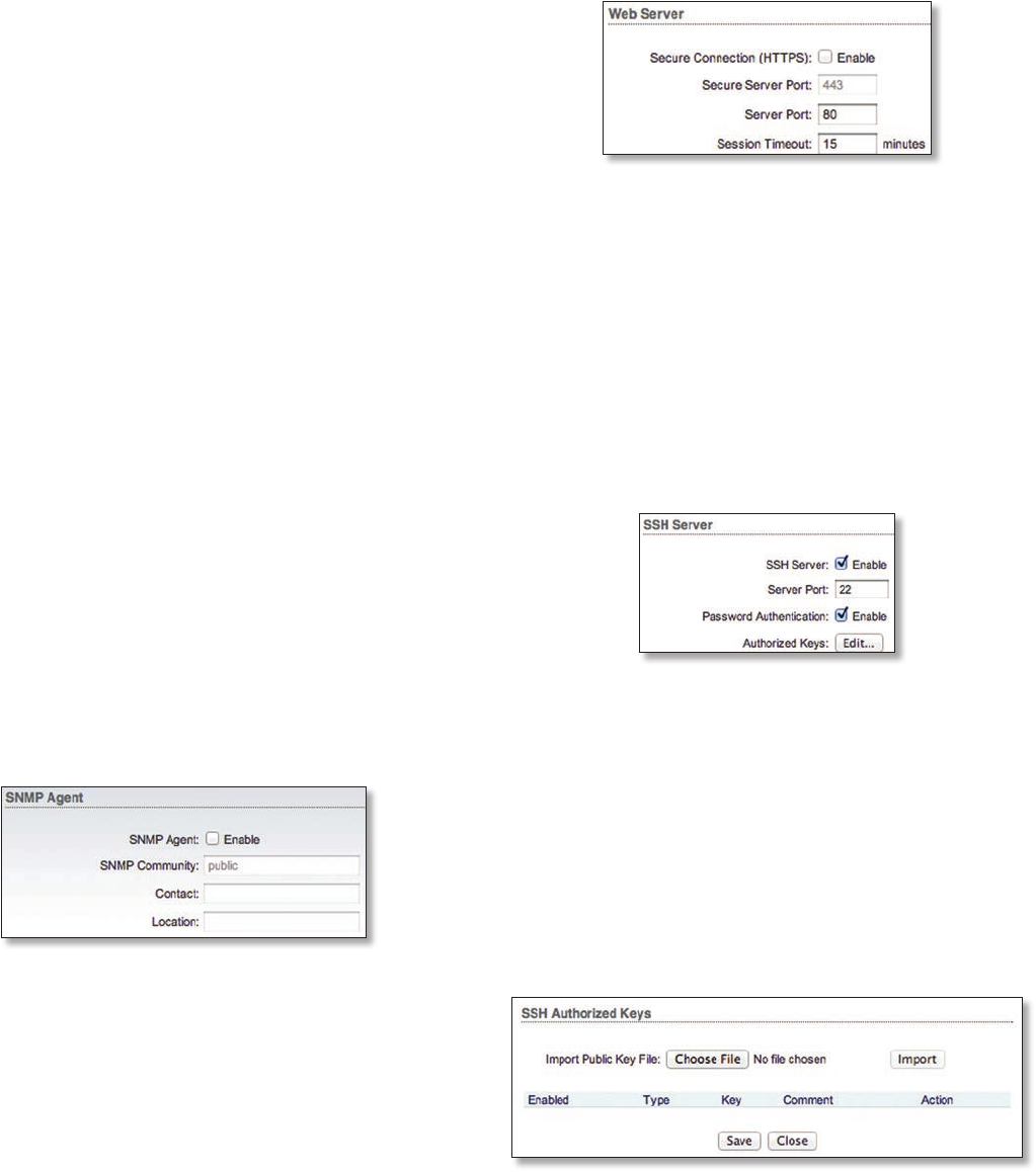
Ping Watchdog
Ping Watchdog sets the airFiberX radio to continuously
ping a user-defined IP address (it can be the Internet
gateway, for example). If it is unable to ping under
the user-defined constraints, the airFiberX radio will
automatically reboot. This option creates a kind of
“fail-proof” mechanism.
Ping Watchdog is dedicated to continuous monitoring of
the specific connection to the remote host using the Ping
tool. The Ping tool works by sending ICMP echo request
packets to the target host and listening for ICMP echo
response replies. If the defined number of replies is not
received, the tool reboots the airFiberX radio.
Ping Watchdog Enables use of Ping Watchdog.
• IP Address To Ping Specify the IP address of the target
host to be monitored by Ping Watchdog.
28
Chapter 8: Services Tab airFiber X User Guide
Ubiquiti Networks, Inc.
• Ping Interval Specify the time interval (in seconds)
between the ICMP echo requests that are sent by Ping
Watchdog. The default value is 300 seconds.
• Startup Delay Specify the initial time delay (in seconds)
until the first ICMP echo requests are sent by Ping
Watchdog. The default value is 300 seconds.
The Startup Delay value should be at least 60 seconds
as the network interface and wireless connection
initialization takes a considerable amount of time if the
airFiberX radio is rebooted.
• Failure Count to Reboot Specify the number of ICMP
echo response replies. If the specified number of ICMP
echo response packets is not received continuously,
Ping Watchdog will reboot the airFiberX radio. The
default value is 3.
• Save Support Info This generates a support
information file.
SNMP Agent
Simple Network Monitor Protocol (SNMP) is an application
layer protocol that facilitates the exchange of management
information between network devices. Network
administrators use SNMP to monitor network-attached
devices for issues that warrant attention.
The airFiberX radio contains an SNMP Agent, which does
the following:
• Provides an interface for device monitoring using SNMP
• Communicates with SNMP management applications
for network provisioning
• Allows network administrators to monitor network
performance and troubleshoot network problems
For the purpose of equipment identification, configure the
SNMP Agent with contact and location information:
SNMP Agent Enables the SNMP Agent.
• SNMP Community Specify the SNMP community
string. It is required to authenticate access to
Management Information Base (MIB) objects and
functions as an embedded password. The airFiberX
radio also supports a read-only community string;
authorized management stations have read access to
all the objects in the MIB except the community strings,
but do not have write access. The airFiberX radio
supports SNMP v1. The default SNMP Community is
public.
• Contact Specify the contact who should be notified in
case of emergency.
• Location Specify the airFiberX radio’s physical location.
Web Server
The following Web Server parameters can be set:
Secure Connection (HTTPS) If enabled, the Web Server
uses secure HTTPS mode.
• Secure Server Port If secure HTTPS mode is used,
specify the TCP/IP port of the Web Server.
Server Port If HTTP mode is used, specify the TCP/IP port
of the Web Server.
Session Timeout Specifies the maximum timeout before
the session expires. Once a session expires, you must log
in again using the username and password.
SSH Server
The following SSH Server parameters can be set:
SSH Server This option enables SSH access to the
airFiberX radio.
• Server Port Specify the TCP/IP port of the SSH Server.
• Password Authentication If enabled, you must
authenticate using administrator credentials to grant
SSH access to the airFiberX radio; otherwise, an
authorized key is required.
• Authorized Keys Click Edit to import a public key file
for SSH access to the airFiberX radio instead of using an
admin password.
- Choose File Click Choose File to locate the new key
file. Select the file and click Open.
- Import Imports the file for SSH access.
- Enabled Enables the specific key. All added keys are
saved in the system configuration file; however, only
the enabled keys are active on the airFiberX radio.
- Type Displays the type of key.
29
Chapter 8: Services TabairFiber X User Guide
Ubiquiti Networks, Inc.
- Key Displays the key.
- Comment
You can enter a brief description of the key.
- Action You have the following options:
• Add Adds a public key file.
• Edit Make changes to a public key file. Click Save to
save your changes.
• Del Deletes a public key file.
- Save Saves your changes.
- Close Discards your changes.
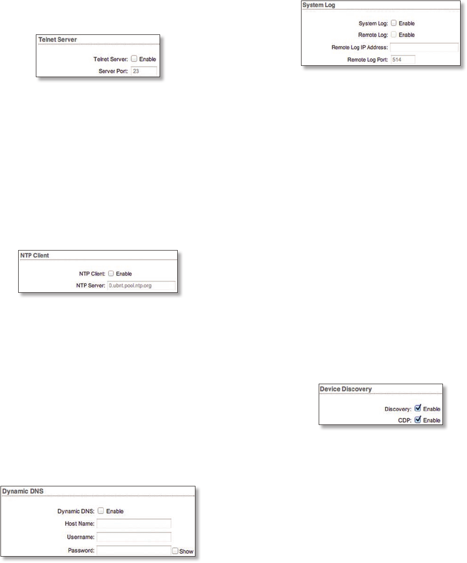
Telnet Server
The following Telnet Server parameters can be set:
Telnet Server This option activates Telnet access to the
airFiberX radio.
• Server Port Specify the TCP/IP port of the Telnet Server.
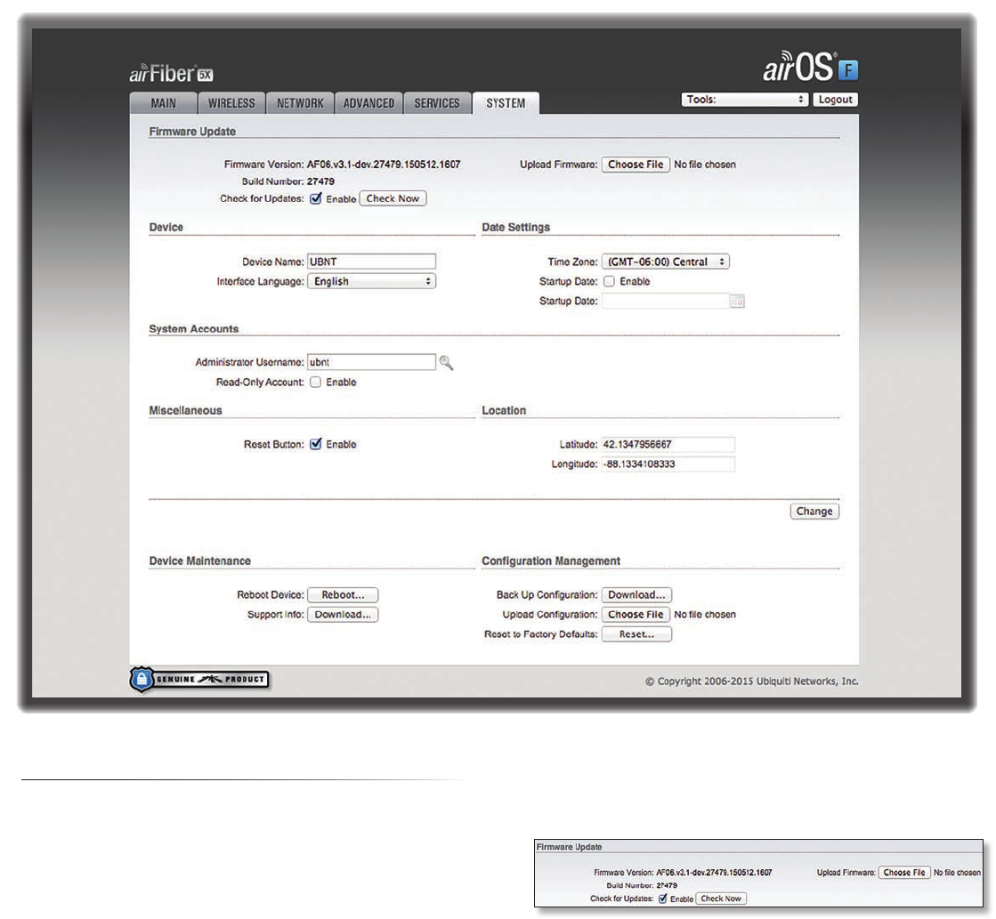
NTP Client
Network Time Protocol (NTP) is a protocol for
synchronizing the clocks of computer systems over
packet-switched, variable-latency data networks. You can
use it to set the system time on the airFiberX radio. If the
Log option is enabled, then the system time is reported
next to every log entry that registers a system event.
NTP Client Enables the airFiberX radio to obtain the
system time from a time server on the Internet.
• NTP Server Specify the IP address or domain name of
the NTP server.
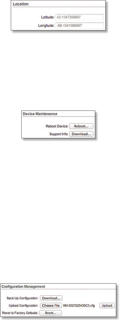
Dynamic DNS
Domain Name System (DNS) translates domain names
to IP addresses; Each DNS server on the Internet holds
these mappings in its respective DNS database. Dynamic
Domain Name System (DDNS) is a network service that
notifies the DNS server in real time of any changes in the
airFiberX radio’s IP settings. Even if the airFiberX radio’s IP
address changes, you can still access the airFiberX radio
through its domain name.
Dynamic DNS If enabled, the airFiberX radio allows
communications with the DDNS server.
• Host Name Enter the host name of the DDNS server.
• Username Enter the user name of the DDNS account.
• Password Enter the password of the DDNS account.
• Show Check the box to display the password
characters.
System Log
System Log This option enables the registration routine
of system log (syslog) messages. By default it is disabled.
• Remote Log Enables the syslog remote sending
function. System log messages are sent to a remote
server, which is specified in the Remote Log IP Address
and Remote Log Port fields.
- Remote Log IP Address The host IP address that
receives syslog messages. Properly configure the
remote host to receive syslog protocol messages.
- Remote Log Port The TCP/IP port that receives syslog
messages. 514 is the default port for the commonly
used system message logging utilities.
Every logged message contains at least a system time and
host name. Usually a specific service name that generates
the system event is also specified within the message.
Messages from different services have different contexts
and different levels of detail. Usually error, warning, or
informational system service messages are reported;
however, more detailed debug level messages can also
be reported. The more detailed the system messages
reported, the greater the volume of log messages
generated.
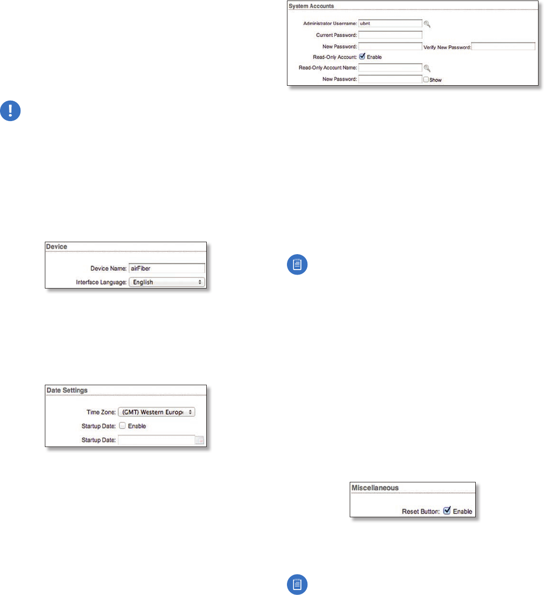
Device Discovery
Discovery Enables device discovery, so the airFiberX
radio can be discovered by other Ubiquiti devices through
the Discovery tool.
CDP Enables Cisco Discovery Protocol (CDP)
communications, so the airFiberX radio can send out CDP
packets to share its information.
30
Chapter 8: Services Tab airFiber X User Guide
Ubiquiti Networks, Inc.
31
Chapter 9: System TabairFiber X User Guide
Ubiquiti Networks, Inc.
Chapter 9: System Tab
The System tab contains administrative options. This
page enables the administrator to reboot the airFiberX
radio, reset it to factory defaults, upload new firmware,
back up or update the configuration, and configure the
administrator account.
Change To save or test your changes, click Change.
A new message appears. You have three options:
• Apply To immediately save your changes, click Apply.
• Test To try the changes without saving them, click Test.
To keep the changes, click Apply. If you do not click
Apply within 180 seconds (the countdown is displayed),
the airFiberX radio times out and resumes its earlier
configuration.
• Discard To cancel your changes, click Discard.
Firmware Update
The controls in this section manage firmware
maintenance.
Firmware Version Displays the current firmware version.
Build Number Displays the build number of the firmware
version.
Check for Updates By default, the firmware automatically
checks for updates. To manually check for an update, click
Check Now.
Upload Firmware Click this button to update the
airFiberX radio with new firmware.
The airFiberX radio firmware update is compatible with
all configuration settings. The system configuration is
preserved while the airFiberX radio is updated with a new
firmware version. However, we recommend that you back
up your current system configuration before updating the
firmware.
32
Chapter 9: System Tab airFiber X User Guide
Ubiquiti Networks, Inc.
This is a three-step procedure:
1. Click Choose File to locate the new firmware file. Select
the file and click Open.
2. Click Upload to upload the new firmware to the
airFiberX radio.
3. The Uploaded Firmware Version is displayed. Click
Update to confirm.
If the firmware update is in process, you can close the
firmware update window, but this does not cancel the
firmware update. Please be patient, as the firmware
update routine can take three to seven minutes. You
cannot access the airFiberX radio until the firmware
update routine is completed.
WARNING: Do not power off, do not reboot, and do
not disconnect the airFiberX radio from the power
supply during the firmware update process as these
actions will damage the airFiberX radio!
Device
The Device Name (host name) is the system-wide device
identifier. The SNMP agent reports it to authorized
management stations. The Device Name will be used in
popular router operating systems, registration screens,
and discovery tools.
Device Name Specifies the host name.
Interface Language Allows you to select the language
displayed in the web management interface. English is the
default language.
Date Settings
Time Zone Specifies the time zone in relation to
Greenwich Mean Time (GMT).
Startup Date When enabled, you are able to change the
airFiberX radio’s startup date.
• Startup Date Specifies the airFiberX radio’s startup
date. Click the Calendar icon or manually enter the
date in the following format: 2-digit month/2-digit
day/4-digit year. For example, for January 5, 2014, enter
01/05/2014 in the field.
System Accounts
You can change the administrator password to protect
your device from unauthorized changes. We recommend
that you change the default administrator password when
initially configuring the device.
Administrator Username Specifies the name of the
administrator.
Key icon Click this icon to change the administrator
password.
• Current Password Enter the current password for
the administrator account. It is required to change the
Password or Administrator Username.
• New Password Enter the new password for the
administrator account.
• Verify New Password Re-enter the new password for
the administrator account.
Note: The password length is 8 characters
maximum; passwords exceeding 8 characters will be
truncated.
Read-Only Account Check the box to enable the
read-only account, which can only view the Main tab.
Configure the username and password to protect your
device from unauthorized changes.
• Read-Only Account Name Specifies the name of the
system user.
• Key icon Click this icon to change the read-only
password.
- New Password Enter the new password for the
read-only account.
- Show Check the box to display the read-only
password characters.
Miscellaneous
Reset Button To allow use of the airFiberX radio’s
physical reset button, check the box. To prevent an
accidental reset to default settings, uncheck the box.
Note: You can reset the airFiberX radio to default
settings via the airFiber Configuration Interface. Go
to the System tab > Reset to Defaults.
33
Chapter 9: System TabairFiber X User Guide
Ubiquiti Networks, Inc.
Location
After the on-board GPS determines the location of the
airFiberX radio, its latitude and longitude are displayed.
If the GPS does not have a fix on its location, then
“Searching for Satellites” will be displayed.
Latitude The latitude of the airFiberX radio’s location is
displayed.
Longitude The longitude of the airFiberX radio’s location
is displayed.
Device Maintenance
The controls in this section manage the airFiberX radio
maintenance routines: reboot and support information
reports.
Reboot Device Initiates a full reboot cycle of the
airFiberX radio. Reboot is the same as the hardware
reboot, which is similar to the power-off and power-on
cycle. The system configuration stays the same after the
reboot cycle completes. Any changes that have not been
applied arelost.
Support Info This generates a support information
file that the Ubiquiti support engineers can use when
providing customer support. This file only needs to be
generated at their request.
Configuration Management
The controls in this section manage the airFiberX radio
configuration routines and the option to reset the
airFiberX radio to factory default settings.
The airFiberX radio configuration is stored in a plain
text file (.cfg file). You can back up, restore, or update the
system configuration file:
Back Up Configuration Click Download to download the
current system configuration file.
Upload Configuration Click Choose File to locate the
new configuration file. Select the file and click Open.
We recommend that you back up your current system
configuration before uploading the new configuration.
Upload Click this button to upload the new configuration
file to the airFiberX radio. Click Apply to confirm.
After the airFiberX radio reboots, the settings of the
new configuration are displayed in the Wireless, Network,
Advanced, Services, and System tabs of the airFiber
Configuration Interface.
Reset to Factory Defaults Resets the airFiberX radio to
the factory default settings. This option will reboot the
airFiberX radio, and all factory default settings will be
restored. We recommend that you back up your current
system configuration before resetting the airFiberX radio
to its defaults.
34
Chapter 9: System Tab airFiber X User Guide
Ubiquiti Networks, Inc.